1
ROTARY MOWER
J40, J44, J46
Operator's Manual No. 9-50552
J I Case
ATenneco Company
casecoltingersoll.com
JENNECO
INTRODUCTION
This manual contains recommended operating procedures,
safety rules, adjustments, maintenance information, assembly and mounting instructions. Read this manual carefully
before operating your rotary mower.
genuine Case replacement parts and the required facilities
is in the position to provide proper repairs in the shortest
time possible.
The definitions " R i g h t , Left, Front, and Rear" as used
throughout this manual relate to the tractor and rotary
mower as the operator is seated facing forward in the
normal operating position of the tractor.
Your J I Case Compact Tractor Dealer is well qualified to
answer any further questions you might have concerning
your rotary mower. Also, if the need should arise, his
Service Department w i t h factory trained technicians.
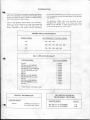
MOWER APPLICATION CHART
MOWER
MODEL
RECOMMENDED
TRACTOR
MODEL
J-40
210, 220, 222
J-44
222, 224, 444, 446, 644, 646
J-46
224, 444, 446, 644, 646
BELT APPLICATION CHART
TRACTOR MODEL
BELT PART NUMBER
210 All
220
220
222
222
224
442
444
444
446
644
644
646
18708
17050
18708
17050
18708
18708
17052
17052
18709
18709
17052
C 21931
013184
Prior to S/N 9656747
S/N 9656747 and after
PRIOR TO S/N 9658189
S/N 9658189 and after
All
All
Prior to S/N 9661261
S/N 9661261 and after
All
Prior to S/N 9698343
S/N 9698343 and after
All
Belt shipped with loader tractor
FOR INSTALLATION ON
PRIOR MODEL TRACTORS
SPECIAL INFORMATION
TRACTOR M O D E L
446 All
TRACTOR MODEL
C 19652 special offset lift
link supplied w i t h tractor
220, 222 prior to S/N 9646800
442, 444 prior to S/N 9646800
3
casecoltingersoll.com
USE K I T
H-38
H-39
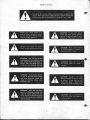
SAFETY RULES
A
A
This safety alert symbol indicates important safety messages in this
manual. When you see this symbol, carefully read the message that
follows and be alert to the possibility of personal injury or death.
Regard your rotary mower as a
piece of power equipment and be
sure this manual is read and understood by all who operate it.
Maintain your tractor and rotary
mower in top operating condition.
A
^^^L
^^V^^^
A
C A U T I O N : Clear the lawn or area
to be mowed of sticks, stones or any
hard objects which could come in
contact w i t h the blades and be
hurled o u t the discharge opening.
A
C A U T I O N : Do not permitchildren
or pets in the area while mowing
and never direct the mower discharge at buildings, people, pets,
windows or cars.
A
W A R N I N G : Keep feet and hands
away f r o m discharge opening and
make no repairs unless both the
tractor engine and attachment drive
are shut o f f and the key is removed
f r o m the tractor.
^ft
^
^^L^^^
^^m^^^
A
casecoltingersoll.com
C A U T I O N : Fill gas tank out of
doors and avoid spilling gasoline.
Do not fill tank w i t h gasoline while
smoking or while engine is running.
C A U T I O N : Never allow children
or young teenagers to operate the
tractor and rotary mower.
CAUTION:
the tractor
Never get on or off
while the mower is
C A U T I O N : Operate in Low range
and use extreme caution on slopes
or inclines. Always back up, and
drive d o w n slopes.
Mow in the
forward and down direction o n l y .
C A U T I O N : Be sure you k n o w how
to stop the tractor and mower at a
moments notice.
A
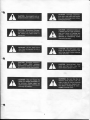
C A U T I O N : Give complete and undivided attention to the job at hand.
A
C A U T I O N : Stop engine, disengage
attachment drive, set parking brake
and remove key when tractor is
unattended.
A
^^ft^^k
^ ^ ^ ^ ^ ^ ^
A
A
C A U T I O N : Do not allow anyone
other than the operator to ride on
the tractor.
C A U T I O N : Disengage attachment
drive
clutch
when
someone
approaches or whenever the mower
is in transport or the lifted position.
A
C A U T I O N : Unbalanced blades are
a hazard and will cause premature
wear and failure of bearings and
spindles. If the blades cannot be
balanced by resharpening, replace
them w i t h new ones.
A
C A U T I O N : Shut off engine, allow
engine to cool and remove key and
spark plug wire(s) before replacing
mower drive belt.
A
C A U T I O N : Spinning Blade - Keep
hands and feet f r o m under the
mower deck to prevent injury.
A
C A U T I O N : Stop and inspect the
mower for damage immediately after striking a foreign object and
repair damage before restarting and
operating the machine.
C A U T I O N : Disengage attachment
drive lever, stop engine and remove
key and spark plug wire(s) before
making adjustments.
5
casecoltingersoll.com
W A R N I N G : Be sure that the attachment drive clutch is o f f , the
engine is shut o f f , the key removed
and the blades have stopped spinning before attempting to clean a
plugged discharge chute.
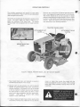
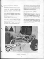
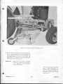
OPERATING CONTROLS
The principle components and controls of your rotary
mower are identified in Figure 1 w i t h the same description
used throughout this manual.
Generally best performance is obtained with the transmission in Low range and the engine running % to full throttle.
The throttle should be set as low as practical to obtain
maximum fuel economy but high enough to prevent engine
lug d o w n or labor which could cause overheating and poor
mowing. Adjust the tractor ground speed w i t h the travel
lever according t o your mowing conditions.
All controls are located near the operator's position on the
tractor. The mower blades are placed in motion by engaging the attachment drive clutch lever. The desired
mowing height can be adjusted w i t h the height selection
lever.
TRACTOR T R A V E L LEVER
FIGURE 1 M O D E L 4 4 6 W I T H M O D E L J-46
4 8 " R O T A R Y MOWER
OPERATION
1. Keep mower blades sharp and balanced as covered in
the Maintenance Section of this manual.
mower set higher than normal; then repeat w i t h the
mower set at desired finished cut height. When mowing
heavy grass, always discharge clippings away f r o m the
uncut area.
2. Operate engine at approximately % to full throttle and
regulate the ground speed Travel Lever according to
mowing conditions. As a general rule, set the throttle
as low as practical to obtain maximum fuel economy
but high enough to avoid engine lug down or labor
which could cause overheating and poor mowing performance.
Unless grass is unusually light, always
operate in " L o w " speed range.
^ ^ ^ ^ ^ ^
^ ^ K ^ ^ B
3. If grass is heavy and higher than normal, results can be
improved by mowing twice. Make the first cut w i t h the
6
casecoltingersoll.com
W A R N I N G : Be sure that the attachment drive clutch is off, the
engine is shut off, the key removed
and the blades have stopped spinning before attempting to clean a
plugged discharge chute.
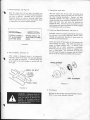
4. Figures 2 and 3 illustrate t w o systems for mowing. If
the grass is high or heavy, always mow to throw the
clippings away f r o m the uncut area. Figure 2. If the
grass is light and more thorough mulching is desired,
discharge the clippings toward the center of the uncut
area. Figure 3. When mowing in this manner, a final
strip of mulched clippings about three to four feet wide
will remain near the center of the lawn. This can be
easily raked up to leave a well groomed appearance.
5. Trimming will be neater and closer by using the right
side of the mower since the clippings will be discharged
away f r o m the object. Also the safety shield over the
discharge opening prevents mowing as close t o objects.
CAUTION:
the tractor
Never get on or off
while the mower is
6. Do not step on the mower deck when getting on or off
the tractor. If mounting the tractor f r o m the right side,
place your right f o o t on the right f o o t rest, your right
hand on steering wheel and left hand on the seat back
and step onto the tractor, swinging your left f o o t
through between the steering wheel and seat.
When mounting f r o m the left side, start w i t h your left
f o o t on the left f o o t rest, your left hand on steering
wheel and right hand on seat back and step onto tractor
swinging your right f o o t through between steering
wheel and seat. Dismount the tractor using the reverse
of the above procedures.
7. The mechanical or hydraulic lift lever is used to raise
the mower into transport and to lower it into cutting
position. A slight pulling pressure on the mechanical
lever will permit the release b u t t o n to be more easily
depressed.
Lower the hydraulic lift until the lift arms are positioned midway in the lift link slots. This w i l l allow the
mower deck and gauge wheels t o follow the contour of
the ground. Do not place the hydraulic lift control
lever in the hydraulic float position when mowing.
The Height Selection settings are explained in the
adjustments section of this manual.
8. Always engage
smoothly.
A
FIGURE 3
7
casecoltingersoll.com
tractor
and
mower
drive
systems
Be certain whoever operates the
mower has read and understands
the Safety Rules in the f r o n t of this
manual.
ADJUSTMENTS
a. Raise mower into transport position
weight f r o m the height selection lever.
C A U T I O N : Disengage attachment
drive lever, stop engine and remove
keys and spark plug wire{s) before
making adjustments.
t o relieve
b. Pull outward on the height selection knob.
c. Move the lever up or d o w n t o the desired height.
d. Push knob into the hole selected.
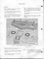
1. Height Selection Lever. See Figure 4 .
2. Gauge Wheels. See Figure 4 .
The mower cutting height is adjustable f r o m V / j " t o
3%" in V2" increments.
Always operate the mower w i t h the gauge wheels on
the ground and all weight off the mower lift links t o
obtain a level and uniform cut. Be sure the gauge
wheels clear the ground when transporting the mower.
To change cutting height:
GAUGE W H E E L
FIGURE 4
ADJUSTMENTS
3. Drive Belt Tension. See Figure 5.
1 WIND KEV CLOCKWISE
BV HAND AS FAR A!
POSSIBLE
AND PLACE
ATTACHMENT
DRIVE IN
ENCAGEMEM POSITION
The mower drive belt is property tensioned when the
front idler spring has 1/8 inch (approximately the
thickness of t w o nickels) gaps between its coils.
IMPORTANT
DECK DRIVE
PULLEY
Ji INSTALL BELT OVER
PULLEYS
AND IDLER
PULLEYS
AS SHOWN
DOUBLE CHECK THAT THE
BELT IS PROPERLY SEATED IN EACH PULLEY WITH
ONLY ONE K DECREE
I*IST BETWEEN SUCCEEDING PULLEYS
Check and adjust the tension on a new
belt after the first 2 0 minutes and the
next hour o f mowing since it is normal
for a belt t o stretch slightly during its
initial run-in period.
J
WIND
KEV
CLOCKWISE
COUNTER.
UNTIL
SHOWS
t.'fl I N C H
IWEEN
COILS
FROM THE SIDE
SPRING
GAP
AS
BE
VIEWED
THE 1*0
I D L E R PULLEYS S H O U L D B E
APPRO"
E V E N OB C L O S E
TO
To increase the belt tension, t u r n the adjusting crank in
a counterclockwise direction while facing the front o f
the tractor.
A
COMMON
CtNTER
LINE
*
AT
PERIODIC
RECHECK
CLEARANCE
COILS
REQUIRED
To decrease the belt tension or t o install or remove the
belt, t u r n the adjusting crank clockwise.
FIGURE 5
8
casecoltingersoll.com
INTERVALS
F O R \ft
INCH
BETWEEN
A N D ADJUST AS
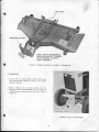
4. Mower Fore-Aft Leveling Links. See Figure 6.
Adjust the leveling links until the distance between the
blade tips and the level surface is the same at both the
f r o n t and rear of the mower. The forward tip may be
slightly lower than the rearward t i p . Never permit the
rearward t i p to be lower than the forward t i p . {This
doubles power consumption in mowing)!
Clean cutting and m i n i m u m horsepower consumption
are dependent upon the mower being level fore and aft.
To adjust, locate the tractor and mower on a level
surface such as your garage floor and place the Height
Selection lever in the 272" setting. Lower the mower
into the cutting position.
5. Mower Side t o Side Leveling. See Figure 6.
Mower side to side leveling is adjusted at the factory.
Should readjustment become necessary, it may be done
by loosening the t w o carriage bolts on the right hand
side that secures the gauge wheel carrier to the deck.
The holes may be slotted if additional adjustment is
required.
After obtaining a level position, retighten
the carriage bolts.
To raise the front of the mower, first loosen the rear
nut on each link and then equally turn the f r o n t nuts
rearward.
To lower the f r o n t of the mower, loosen the f r o n t nut
of each link and t u r n the rear nuts forward.
Position blades so that they are parallel to the tractor
frame (fore and aft line) before measuring clearance.
Side to side leveling should be done on a level surface,
such as your garage floor w i t h the height selection lever
in the 2^^" setting and the mower lowered into the
cutting position. Be sure the mower is level fore and
aft before checking side t o side level.
Check blade heights as close to the front and rear edges
of the mower blades as possible. Be sure to tighten
both f r o n t and rear nuts when checking blade height.
TWO C A R R I A G E BOLTS
FIGURE 6
ADJUSTMENTS
9
casecoltingersoll.com
MAINTENANCE
^
^
^^^^H^^
C A U T I O N : Disengage attachment
drive lever, stop engine and remove
keys and spark plug wire(s) before
making adjustments.
MOWER B L A D E BOLTS
1. Mower Blade Bolts. See Figure 7.
Before operating the mower for the first time,
the bolts holding the blades. They must be tight.
the first 8 hours of operation, check them again.
ever the blades are removed, it is good practice to
new lockwashers under the bolts, and again
tightness after the next 8 hours of operation.
check
After
Wheninstall
check
2. Bent Blades. See Figure 7.
TIPS S H O U L D BE W I T H I N
% " OF SAME H O R I Z O N T A L
PLANE.
Check for bent blades before mounting the mower and
after impact. Blade tips should be w i t h i n % inch of the
same horizontal plane. Align all six blade tips, t w o at a
time as shown in Figure 7 to determine this. Mowing
with bent blades will cause missed strips and a poor
mowing job.
Bent blades should be replaced
immediately.
FIGURE 7
a. Remove the deck belt guard.
3. Mower Gauge Wheels. See Figure 8.
b. Relax the idler pulley tension by pivoting it towards
the f r o n t of the deck w i t h a 9 / 1 6 " box wrench
placed on the hex n u t .
Remove the gauge wheels after each 10 hours of mowing and lubricate the bushings and axle bolts w i t h
chassis grease. As an alternate to grease, the wheels
can be oiled after each four hours of operation. Make
sure the oil penetrates to the inside of the bushings by
holding the deck at an angle while lubricating.
c. Remove the old belt.
d. Place the new belt around the 3 spindle pulleys and
idler.
4. Mower deck belt replacement. See Figure 8.
The deck belt is automatically tensioned by a spring
loaded idler pulley and does not require adjustment.
e. Rotate system by hand t o check for free operation
and idler take up.
Install a new belt in the following manner:
f.
Replace deck belt guard.
HEX N U T
casecoltingersoll.com
5. Sharpening Blades. See Figure 9.
7. Cleaning the mower deck.
With the engine shut off and after the blades have
stopped spinning, check the mower blades periodically
for nicks or dullness. Damaged, dull or improperly
sharpened blades can cause a shattered, rather than,
clean cut and brown areas of grass may develop. Refer
t o Figure 9 for the correct sharpening angle.
With the engine shut off and after the blades have
stopped spinning, check and clean out the inside of
the deck housing periodically.
Remove any grass
wrappings between the blade mounting plates and
spindle housings. Grass wrappings, if allowed to accumulate, may w o r k their way under the bearings and
damage the seals. Excessive grass accumulation in the
deck housing w i l l waste horsepower and cause plugging
and streaking, as well as, corrosion.
8. Tractor and Engine Maintenance. See Figure 1 1 .
CORRECT ANGLE
OF S H A R P E N E D
C U T T I N G EDGE
Complete tractor and engine maintenance instructions
are outlined in your tractor Operator's Manual. When
mowing, give particular attention to areas which are
affected by grass accumulation.
WRONG ANGLE TO
SHARPEN CUTTING
EDGE
Check and brush off the engine air intake screen and
heat exchanger fins daily. Also check and clean the
engine air cleaner element daily.
If mowing, under
particularly dry or dusty conditions, a precleaner
which fits over the regular element is available f r o m
your J \e Dealer. This precleaner can be washed
out w i t h soap and water as necessary and will extend
the life of the dry element furnished w i t h the tractor.
FIGURE 9
6. Balancing Blades. See Figure 10.
After a blade is sharpened, check it for balance by
inserting a dowel in the center hole and place between
t w o level edges as illustrated. A balanced blade w i l l
center itself so the cutting edges are parallel w i t h the
level edges.
FIGURE 11
FIGURE 10
9. Tire Pressure
A
Maintain the tires at equal and recommended pressures.
Refer to your tractor Operator's Manual.
C A U T I O N : Unbalanced blades are
a hazard and will cause premature
wear and failure of bearings and
spindles. If the blades cannot be
balanced by resharpening, replace
them w i t h new ones.
It
casecoltingersoll.com
INSTALLATION
I. ASSEMBLY
2. Select the appropriate belt using application chart on
page 3 .
The belt part number is stamped into the
outer covering of the belt. Select the two short lift
links if installation is to be on a low clearance (200 or
600 series) tractor.
1. Before assembling the mower, lay o u t and check the
individual components. See Figure 12.
The J-40 Mower is shipped w i t h one drive belt and one
set of lift links since it is intended for use on low
clearance (200 series) tractors o n l y .
Select the t w o long lift links if the installation is to be
on a Model 444.
The J-44 and J-46 Mowers are shipped w i t h t w o drive
belts and t w o sets of lift links since they may be
mounted on either low or high clearance {200, 400 or
600 series) tractors.
F I G U R E 12
Select one long lift link and special link P/N C 19652
(supplied w i t h tractor) if the installation is to be on a
Model 446.
M O D E L J-46 R O T A R Y MOTOR - DISASSEMBLED
3. Assemble the lift links to the mounting bracket and
secure w i t h cotter keys as shown in Figure 13.
NOTE
The special link P/N C 19652 for the Model 446
(supplied w i t h tractor) should be installed on the right
hand side.
Do not preassemble the mounting bracket
to the mower deck as shown in Figure 13.
It is easier to install the mounting bracket
t o the tractor first and then attach the mower
deck to it.
The slotted end of the links will be connected to the
tractor life arms when mounted.
12
casecoltingersoll.com
II. MOUNTING
1. Locate tractor on a level surface. Check tires for equal
and recommended pressures as found in your tractor
Operator's Manual.
2. Before attaching the mounting bracket, t u r n the
adjusting crank counterclockwise as far as possible to
provide mounting clearance at the front axle. Refer to
Figure 14.
ADJUSTING CRANK
FIGURE 14
13
casecoltingersoll.com
BELT A D J U S T M E N T
3. Position the mounting bracket under the f r o n t of the
tractor and onto the anchor pins as shown in Figure 15.
Raise the f r o n t of the bracket and release the snap fast
pins to lock in place.
NOTE
4. Lower the lift arms f u l l y . Position the lift links on the
inside o f the lift arms. Put a plain washer on each
clevis pin and install in the f r o n t hole o f the lift arm
f r o m the inside. Secure the links w i t h the safety pins
at the outside. Refer t o Figure 15.
Model 644 and 646 - The mounting bracket
is attached w i t h the t w o clevis pins and
safety pins connected t o each f r o n t side o f
the frame.
5. Raise the lift arms into the transport position.
SNAP FAST PIN
FIGURE 15 M O U N T I N G T H E J-46 MOWER M O U N T I N G B R A C K E T
6. Place the height selection lever in the V/a" setting t o
gain additional clearance and slide the mower under the
tractor f r o m the right liand side and align the deck w i t h
the attaching holes in the mounting bracket. Lower
the mounting bracket t o the mower deck. Refer t o
Figure 16.
9. With t h e engine shut o f f , key removed, and cool t o
the t o u c h , engage the attachment drive lever. Raise
the hood and remove the spark plug wire(s) f o r safety.
Insert the drive belt in front of the idler pulleys, between the fan and heat exchanger and o n t o the
attachment drive clutch pulley. Turn the adjusting
crank clockwise until the belt can be easily placed
around the idler pulleys and onto the mower drive
pulley.
7. Install the Fore-Aft leveling links t o the mounting
bracket as illustrated in Figure 16.
8. Connectthe mounting bracketto the tabs on the mower
deck w i t h the clevis pins and safety pins provided.
NOTE
^^^^^L
Lifting the mower deck upward slightly will
aid in aligning the holes between the mounting bracket and deck tabs.
^^^^fljjjft
14
casecoltingersoll.com
C A U T I O N : Shut o f f engine, allow
engine t o cool and remove key and
spark plug wire(s) before replacing
mower drive belt.
r
10. Check to make sure the belt is properly located in each
pulley. Turn the adjusting crank counterclockwise t o
tension the belt until the idler spring coils open 1/8
inch (approximately the thickness of two nickels. See
Figure 5 and 14.) Disengage the attachment drive lever
and reconnect the spark plug wire(s).
IMPORTANT
Before
follow
in the
section
operating the mower, review and
the recommendations outlined
adjustments and Maintenanceof this manual.
The J I Case Company reserves the
right to make improvements in
design changes in specifications at
any time w i t h o u t incurring any
obligations to install them on units
previously sold.
Printed in U. S. A.
40
i
15
casecoltingersoll.com
CMTHO
casecoltingersoll.com