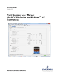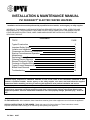
1
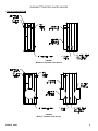
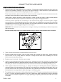
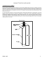
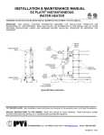
INSTALLATION & MAINTENANCE MANUAL
PVI DURAWATT® ELECTRIC WATER HEATERS
Installation and service must be performed by a qualified service installer, service agency or utility supplier.
IMPORTANT: THIS MANUAL CONTAINS INFORMATION REQUIRED FOR INSTALLATION, OPERATION AND
MAINTENANCE OF THIS EQUIPMENT. READ AND FOLLOW THE INFORMATION IN THIS MANUAL AND ALL
OTHER PROVIDED INSTRUCTIONS, LABELS AND MARKINGS BEFORE INSTALLING, OPERATING OR
SERVICING THIS UNIT.
CONTENTS
TOPIC
Typical Construction
Important Safety Notice
Location and Installation
Clearances and Electrical Connections
Start-up Procedures and Operation
Maintenance
Replacing Electric Elements
Cleaning Electric Elements
Element Continuity Checks
Contactor to Element Wiring
Typical Current Measurement
Bolted Head Removal
Troubleshooting
PAGE
2
3
4
5
6
7
8
9
10
11
12
13
14
WARNING: Improper installation, adjustment, alteration, service or maintenance can cause property damage,
personal injury, exposure to hazardous materials or loss of life. Refer to the information contained in this
manual. A qualified installer, service agency or the utility supplier, who must read and follow the supplied
instructions before installing, servicing or removing this appliance, must perform installation and service.
WARNING: Do not use this appliance if any part has been under water. Immediately call a qualified service
technician to inspect the unit and to replace any part of the control system, and any other items affecting safe
appliance operation. Failure to follow these instructions can cause property damage, personal injury, or loss of
life.
TO THE INSTALLER: After installation, these instructions must be given to the equipment user or left near the appliance.
SPECIAL INSTRUCTIONS TO THE OWNER: Retain this manual for future reference. These instructions contain
important information that will help you in maintaining and operating this appliance.
PV 500-6
09/07
DURAWATT® ELECTRIC WATER HEATER
TYPICAL CONSTRUCTION
FIGURE 1
Without 23” Diameter Tank Access
FIGURE 2
With 23” Diameter Tank Access
PV500-6 09/07
2
DURAWATT® ELECTRIC WATER HEATER
IMPORTANT SAFETY NOTE
It takes only 5 seconds of skin contact with 140°F water to cause a
second degree burn! You must protect against high water temperatures at all
lavatories, tubs, showers and other points of hot water contact.
Accidental scalding from high water temperatures is a greater
risk in some types of installations. Some examples are:
HOMES FOR THE MENTALLY HANDICAPPED
HOMES FOR THE PHYSICALLY HANDICAPPED
HOSPITALS AND NURSING HOMES
ELDER CARE FACILITIES AND REST HOMES
ORPHANAGES AND CHILD CARE FACILITIES
OTHER INSTALLATIONS - WHERE RESPONSE TO CONTACT WITH HOT WATER
MAY BE SLOWER OR WHERE THE DANGER OF HOT WATER CONTACT IS
GREATER
Thermostatically controlled mixing valves must be used in the
design of the potable hot water system.
Potable hot water should be tempered to no more than
110°F when used for bathing or other personal uses.
Good engineering practice mandates the use of thermostatically controlled
mixing valves set at 120°F or less to keep the delivered water temperature below
scalding temperatures.
PV500-6 09/07
3
DURAWATT® ELECTRIC WATER HEATER
CHECKING EQUIPMENT BEFORE YOU INSTALL
Inspect the unit completely upon receipt from the freight carrier before signing the bill of lading. Inspect the appliance and
all accompanying parts for signs of impact or mishandling. Verify the total number of pieces shown on packing slips with
those actually received. Contact the freight carrier immediately if any damage or shortage is detected.
WARRANTY
Factory warranty does not cover improper installation or operation. (See warranty for complete details).
Warranty exclusions include but are not limited to failure or malfunctions resulting from:
1.
2.
3.
4.
Failures to properly apply, install, operate, or maintain the appliance in accordance to printed instructions.
Abuse, alteration, accident, fire, flood and the like.
Sediment or lime buildup, freezing or any other conditions causing inadequate circulation.
Corrosive or contaminated atmosphere.
CODES
The equipment shall be installed in accordance with those installation regulations in force in the local area where the
installation is to be made. These shall be carefully followed in all cases. Authorities having jurisdiction shall be consulted
before installation is made. In the absence of such requirements, the installation shall conform to the latest edition of the
National Electrical Code.
LOCATION
1. Locate the unit in a clean and dry area as close as possible to the greatest hot water usage and as near to electrical
power as practical.
2. Install the unit on a firm, level foundation.
3. Locate the foundation on a pitched floor near a suitable drain, or make other provisions to prevent contact to areas
of the building subject to water damage should the boiler or a water connection leak. The drain must be sufficient to
contain water in excess of 210°F.
INSTALLATION
WARNING: Use industry standard safe rigging methods when attempting to lift or move this product. Failure to
follow these instructions could result in property damage, serious injury or death. One common method includes
the use of straps and spreader bars, lifting from the water heater base skid assembly.
1. Check the data decal on the heater. Be sure the electrical supply is adequate for the installation.
2. Carefully remove all shipping supports and bracing. (Float type devices have shipping plugs blocking the float).
3. Install shut-off valves and unions on the inlet and outlet water piping for servicing. Use caution when threading pipe
nipples into tank connections to prevent cross threading, or over-tightening. Always use a back-up wrench on tank
nipples when tightening unions, valves, etc.
4. Insulate hot water and return circulation lines. Insulate cold water supply lines if subject to freezing during shutdown
periods. IMPORTANT: Do not use the plumbing connected to the appliance as a ground for welding or any
other purpose.
5. The water heater is equipped with a temperature and pressure relief valve(s) rated for the input. Pipe the relief valve
discharge to a suitable open drain. The drain pipe may not be smaller than the relief valve opening and must be
secured to prevent it from lifting out of the drain under discharge pressure. Do not install valves or restrictions in the
discharge line.
6. Pipe the drain valve to a suitable open drain.
PV500-6 09/07
4
DURAWATT® ELECTRIC WATER HEATER
SERVICE CLEARANCES
Allow sufficient space to provide adequate clearances on all sides for service and inspection. Recommended clearance is
24” at the top and front, 18” at left and right sides of the appliance. Optional equipment may increase the clearance
requirements. Allow sufficient space for installing and servicing connections such as water, electrical, pump and other
auxiliary equipment.
CLEARANCES TO COMBUSTIBLE SURFACES
The appliance must not be installed on a combustible floor, or on a non-combustible floor covering combustible material.
Clearance to unprotected combustible material must be 6” minimum at top, sides and rear, and 24” minimum in front.
Recommended access for service is 18” at sides and rear and 42” in front.
ELECTRICAL CONNECTIONS
Check rating plate on front for correct voltage, phase and amperage. Refer to wiring diagram for control components
mounted on heater.
Use proper wire size and branch circuit protection as required by National Electrical Code and state and local codes. The
PVI electric water heater specification sheets show number and size of power connectors furnished with the heater for
minimum 90°C copper connecting wire.
Use correct size ground wire, attach to pressure connector provided and marked with decal “GR.”
Connect supply feeders to distribution block (or circuit interrupter if furnished) inside electrical enclosure on the heater
IMPORTANT: Check all wiring connections in heater and element enclosure to assure tightness prior to energizing.
NOTE: Use only copper wire of proper sizing for incoming service. Damage resulting from use of aluminum
wiring is excluded from coverage under the warranty of this unit.
ELECTRONIC LOW WATER CUTOFF
The device consists of a probe in the tank that acts as a switch, closed when submerged in water and open when the
water level is below the probe, preventing heating elements from energizing. The probe should be kept free of scale
buildup to insure operation.
OPTIONAL EQUIPMENT
Shunt Trip Circuit Interrupter (optional on all models): The shunt trip, wired in the non-automatic circuit interrupter, is a
safety device designed to open the circuit interrupter and prevent the elements from energizing if the control panel door is
opened.
Time Sequencer (optional on all models):
Time sequencing is optional and used in lieu of the proportional sequencer. It is a series of time delay relays wired to the
contactors which allows approximately a 40 second delay in energizing each succeeding heating element when the
controls call for heat. This prevents all heating elements from energizing at the same time.
Proportional Sequencer (optional on all models): Progressive sequencing (orbital) equalizes the on time for each
contactor and heating element. The heating elements are staged-on based on the demand on the water heater. The
control gives visual, indication of stages that are on. In the event of power interruption, all contactors are turned off. When
power is resumed, the control will re-stage the elements beginning with number one.
PV500-6 09/07
5
DURAWATT® ELECTRIC WATER HEATER
START-UP PROCEDURES AND OPERATION
1. The tank must be full of water before turning on electricity. If elements are energized without water in the tank, they
will burn out immediately. Warranty is void on dry starts. Use multimeter to check resistance to ground between all
element terminals and the element mounting flange. (See table 1, page 10)
Fill the heater with water. Open the relief valve to allow air in the tank to escape. Be sure all connections into the tank
are tight as leaks at tank fittings or heating elements can cause damage.
Check inside of electrical enclosure for leaks with tank full of water at water line pressure. Heating element gaskets
are pressure tested at factory but may leak if unit has been in dry storage for a long period of time.
If leaks are present, tighten all four nuts uniformly on the element mounting flange in a criss-cross pattern. Tighten
one nut, then the nut on the diagonal from the first nut. Next, tighten the nut adjacent to the second nut, and then the
nut diagonal from the third nut. Repeat this sequence until all nuts are tight. Each nut should be tightened to 15 foot
pounds of torque. To avoid warping the flange, do not over tighten.
IMPORTANT: All leaks must be corrected prior to turning on electricity to avoid damage to electrical components
within the enclosure.
Electric element (design may vary): 3 phase elements have 3 terminals; 1 phase elements have 6 terminals
FIGURE 3
2. Check all electrical connections for tightness before turning the unit on.
3. Energize manual disconnect switch. Check for proper voltage (with voltmeter) on power circuit. Voltage should not
vary more than 5% from voltage shown on data plate. If voltage exceeds these limits, immediately turn off main
disconnect and contact utility company.
4. Energize control circuit switch. Check for proper voltage.
5. Check for proper amperage with ammeter on power circuit. Amperage should not vary more than 5%, when under full
load, from amperage shown on data plate. (Element Continuity Checks, page 10). If amperage exceeds these limits,
immediately turn off main manual disconnect and refer to Electric Water Heater Trouble Shooting Guide (page 14).
6. Check magnetic contactors for noise. If noisy, i.e., buzzing or chattering, turn off main power disconnect, disassemble
contactor and blow out foreign particles. Drill filings, dirt or other particles can cause pitting of points which will in turn
burn out contactor and/or wire. Extra care has been taken during fabrication and inspection for cleanliness; however,
field installation is often responsible for debris collecting on the contactor points.
7. The top thermostat is a temperature limiting safety device set at 200°F. The upper operating thermostat is factory set
at 130°F. The lower operating thermostat is set at 120°F Adjust stored water temperature by turning the Operating
thermostat dial to the desired temperature. The Upper Operating and Operating thermostats should be set minimum
10°F higher.
PV500-6 09/07
6
DURAWATT® ELECTRIC WATER HEATER
8. If an optional proportional sequencer is furnished, adjust set point to desired water temperature. (All other temperature
controls must be set above the sequencer’s set point.) Refer to manufacturer’s product literature for servicing,
operation and maintenance of proportional sequencer.
9. After startup and with the water heater operating, allow the water in the tank to reach the desired temperature and deenergize the heating elements. Draw hot water from a nearby faucet or outlet until the heating elements come back
on. This will check for proper operation of the thermostats and other operating controls.
IMPORTANT: After approximately 30 minutes of operation, turn off all power to the unit. With main disconnect
off, check each wire connection and fuse clip for elevated temperature. If an elevated temperature is noted, there
is a loose connection at the point of greatest heat. All connections must be tight for proper performance.
MAINTENANCE
A preventative maintenance program is required to ensure a long trouble-free life of the water heater.
Maintenance Schedule
COMPONENT
OPERATION
INTERVAL
REQUIRED
Tank
Sediment Removal
Every 3 Months
Flushing
Relief Valve
Inspect
Every 6 Months
Test
Electrical Connections
Inspect
Monthly
Inspect for wire discoloration
Electric Elements
Check
Every 6 Months
Amp Draw
Electric Elements
Remove & Clean
See Page 9
Flushing
1. Turn off the heater electrical disconnect switch.
2. Open the drain valve and allow water to flow until it runs clean.
3. Close the drain valve when finished flushing.
4. Turn on the heater electrical disconnect switch.
Draining the Tank
The heater must be drained if it is to be shut down and exposed to freezing temperature. Maintenance and service
procedures may also require draining the heater.
1. Turn off the heater electrical disconnect switch.
2. Close the cold water inlet and hot water outlet valve to heater.
3. Open a relief valve to vent the tank pressure.
4. Open the heater drain valve.
5. If the heater is being drained for an extended shutdown, it is suggested the drain valve be left open during this period.
PV500-6 09/07
7
DURAWATT® ELECTRIC WATER HEATER
Sediment / Lime Scale Removal
Waterborne impurities consist of the particles of soil and sand which settle out and form a layer of sediment on the bottom
of the tank and adheres to heat exchange surfaces. The amount of calcium carbonate (lime) released from water is in
direct proportion to water temperature and usage. The higher the water temperature or water usage, the more lime
deposits are dropped out of the water. Lime accumulation not only reduces the life of the equipment but also reduces
efficiency of the heater.
T & P Relief Valve
The pressure relief valve should be checked at regular intervals by manually opening the valve. The openings inside the
valve may become restricted by a buildup of scale and become inoperative. If the valve does not open and close properly
and does not blow off internal pressure when tested, it must be replaced. Shut down heater, relieve internal pressure and
replace relief valve with a like kind or one meeting the requirements stated on the rating decal located adjacent to the
relief valve mounting location.
Low Water Cut-Off
The standard low water control is electronic. Inspection should be made of the electrode on water heaters equipped with
electronic low water devices.
Electrical Connections
Check all electrical connections approximately one to two weeks after initial start-up to assure tightness. Heating and
cooling from operation can loosen connections. Visually inspect wire terminal points for any discoloration on a monthly
basis. Discoloration is likely due to a loose connection at the point nearest discoloration. Check Contactors periodically
and clean if necessary and repair or replace pitted points caused by foreign particles. Check Fuses periodically for
continuity and replace if necessary with the same dual-element type.
REPLACING ELECTRIC ELEMENTS
Some electric heating elements installed in dished heads may be factory bent to allow clearance from adjacent elements.
Replacement elements must be identical to the original equipment installed. The Bend Angle Stamp # is required for all
replacement electric element requests. Important: Install the element facing away from the center of the head.
Typical Electric Element
FIGURE 4
BEND ANGLE
STAMP
25°
#1
18°
#2
FIGURE 4
Note: No stamp on element flange means that element is not bent.
PV500-6 09/07
8
DURAWATT® ELECTRIC WATER HEATER
CLEANING ELECTRIC ELEMENTS
Electric immersion INCOLOY® sheath elements are wound at high wattage ratings and must be completely covered by
water while in operation. Otherwise, they overheat and burn out. Scale from the water will collect on the sheathing of the
element over a period of time and must be removed periodically to extend the life of the element. Water in some areas will
produce the scale buildup more rapidly than other areas. The rapidity of the scale buildup is also determined by the watt
density of the element.
It is good maintenance practice to remove and clean 80 W/in² (18kW) density elements on a monthly basis. The interval
between removal and cleaning can usually be extended to six months when 40 W/in² (9kW) density elements are
installed. Most installations where 20 W/in² (4 1/2kW) density elements are used, require only annual cleaning. Elements
are cleaned by soaking in a scale dissolving solution. A 30” piece of four or six inch PVC pipe with a cap on one end
makes an ideal container for element cleaning. (See figure 5.) Contact a chemical supply house for advice on the proper
cleaning solution for your area.
Element Cleaner
FIGURE 5
PV500-6 09/07
9
DURAWATT® ELECTRIC WATER HEATER
ELEMENT CONTINUITY CHECKS
I.
II
III.
I.
ELEMENT RATING
kW
VOLT
18
480
18
18
9
9
9
4.5
4.5
4.5
PV500-6 09/07
240
208
480
240
208
480
240
208
CHECK OPEN
COILS
II.
OHM
OHM READING 1
READING
LEG OPEN
NORMAL
IV.
V.
III.
IV.
OHM READING
2 LEGS OPEN
OHM READING 3
LEGS OPEN
A-B
26
78
∞
∞
B-C
26
39
39
∞
C-A
26
39
∞
∞
A-B
7
20
∞
∞
B-C
7
10
10
∞
C-A
7
10
∞
∞
A-B
5
15
∞
∞
B-C
5
7.5
7.5
∞
C-A
5
7.5
∞
∞
A-B
51
153
∞
∞
B-C
51
76.5
76.5
∞
C-A
51
76.5
∞
∞
A-B
13
39
∞
∞
B-C
13
19.5
19.5
∞
C-A
13
19.5
∞
∞
A-B
10
30
∞
∞
B-C
10
15
15
∞
C-A
10
15
∞
∞
A-B
102
306
∞
∞
B-C
102
153
153
∞
C-A
102
153
∞
∞
A-B
26
78
∞
∞
B-C
26
39
39
∞
C-A
26
39
∞
∞
A-B
19
58
∞
∞
B-C
19
29
29
∞
C-A
19
29
∞
∞
TABLE 1
V.
OHM READING
TERMINAL TO
FLANGE
DEPENDING ON
THE SEVERITY
OF THE SHORT,
THE OHM
READING MAY
VARY FROM
ZERO, (DIRECT
SHORT) TO
SEVERAL
HUNDRED
OHMS (PARTIAL
SHORT). IN
ANY CASE
WHERE THE
OHM READING
IS NOT INFINITY,
THE ELEMENT
SHOULD BE
REPLACED
10
DURAWATT® ELECTRIC WATER HEATER
TYPICAL SINGLE PHASE WIRING
TYPICAL THREE PHASE WIRING
FIGURE 8
FIGURE 6
TYPICAL WIRE TERMINATIONS
FIGURE 9
FIGURE 7
FIGURE 10
PV500-6 09/07
11
DURAWATT® ELECTRIC WATER HEATER
TYPICAL CURRENT MEASUREMENT
FIGURE 11
FIGURE 12
3 Ø AMPS PER ELEMENT
KW-VOLTAGE
1 Ø AMPS PER ELEMENT
AMPS PER LEG
AMPS TOTAL
AMPS PER LEG
AMPS TOTAL
*14 kW-600V
13 1/2
13 1/2
—
—
*7 kW-600V
7
7
—
—
18 kW-480V
22
22
—
—
9 kW-480V
11
11
—
—
4.5 kW-480V
5 1/2
5 1/2
—
—
18 kW-240V
44
44
25
75
9 kW-240V
22
22
13
38
4.5 kW-240V
11
11
6
18
18 kW-208V
50
50
29
87
9 kW-208V
25
25
15
44
4.5 kW-208V
12 1/2
12 1/2
7
22
TABLE 2
NOTE: Elements are usually wired to contactors in groups, in order to maintain an amperage draw of close to, but not more
than, 50 amps per contactor.
*Applications for 600V use a re-rated 480V element. Therefore, the 40W/in.2 is rated for 14 kW instead of 9 kW.
PV500-6 09/07
12
DURAWATT® ELECTRIC WATER HEATER
SUPERTANK™ BOLTED HEAD REMOVAL
SUPERTANK™ water heaters and storage tanks will have one or more removable heads or bolted tank sections. The
heads are used to mount an energy module (i.e. TURBOPOWER® module, electric elements, QUICKDRAW® or steam or
water heat exchanger heating elements) or bolted head for access to the tank. If a head or module is removed during the
course of maintenance, replace the O-ring and all special high quality 9/16”-12 NC, grade 8 bolts, washers and nuts with
identical parts available from your PVI representative or directly from PVI. Do not reuse or substitute these special
fasteners with similar grade 8 bolts, washers and nuts. Install the flange bolts and nuts with a flat washer under each bolt
head and nut. First, snug them in an alternating star pattern. Then, using a calibrated torque wrench, and in an alternating
star pattern, tighten the bolts in 2 increments: 95 ft lbs and 145 ft lbs. Use a small amount of silicone RTV to hold the oring in place while positioning the flanged head or heat exchanger. Apply adhesive sparingly!
Contact PVI at 1-800-433-5654 for replacement Fastener Kits and O-Ring Replacement Instructions.
IMPORTANT: Mark one hole on head and on tank flange for reference when removing head. Be certain to align these
holes during reassembly to insure the original gasket or O-ring mating surfaces will be correctly positioned.
Typical Vertical SUPERTANK™ Bolted Head Attachment
FIGURE 13
PV500-6 09/07
13
DURAWATT® ELECTRIC WATER HEATER
ELECTRIC WATER HEATER TROUBLESHOOTING GUIDE
TROUBLE
PROBABLE CAUSE
REMEDY
Thermostat(s)
Check to assure proper thermostat setting.
Contractors will not pull in
Check continuity between all three thermostats or pressure
controls. Complete circuit. If one is open, it must be replaced.
Control circuit switch is in OFF position
Close switch. (Turn to ON position)
Control circuit fuse blown
Isolate cause for failure and replace fuse.
Contractor(s) coil open
Check continuity. Replace coil if not a complete circuit.
Time delay sequencer not operating
Check for 120 volts to coil on first sequencer step. Allow ample
time for additional steps to energize. If steps do not energize in
reasonable time, replace only the defective relay step. See
wiring diagram.
Proportional sequencer not operating
Check for 120 volts to line connection (L) on sequencer. Check
fuse for continuity. See wiring diagram. Consult factory.
Low water cutoff open
Check for open circuit. Check water level in tank. Replace low
water cutoff if defective.
Heating elements
Check for open legs. (See table 2).
Heater not large enough to satisfy peak
demands
Add booster or additional kw input. Consult local PVI
representative.
Hot water lines not insulated
Add insulation; it will protect against heat loss and save on cost
of operation.
Power fuse(s) blown
Check fuses for continuity. Replace if blown. If blown, determine
cause of break before replacing with same type fuse.
Contractor(s) not closing
Check coil for continuity. If defective, replace.
Thermostat(s) not correctly set
Check to assure proper thermostat control setting.
Element(s) not heating
Check for proper amperage draw. Check for proper ohm
resistance. Replace if defective. Consult factory.
(See table 1)
Loose connections
Tighten all connections. If charred, replace wire with wire of
same type and size.
Dirty or pitted contactor points
Remove contactor points and inspect. If dirty, clean with emery
paper. CAUTION: Point must remain flat. If pitted or burned,
contractor points must be replaced.
Blown fuses
Loose connection. Defective element
Check all connections for tightness. Check ohm resistance in
electric elements. Replace.
High or low
voltage
Local utility
Check with local utility.
High or low
amperage
High or low voltage. Defective element
Check with local utility. Low amperage, check fuses, tighten
connections. Check ohm resistance on elements.
Wire burned
or melted at
element
Loose connections. Water leaking on elements
Tighten connection and replace wire. Isolate leaking water and
repair. Replace wire with same type and size.
No hot water
Insufficient hot
water
Burned or
discolored wires
PV500-6 09/07
14