1
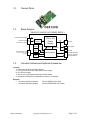
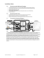
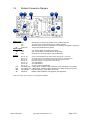
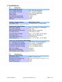
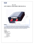
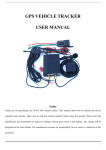
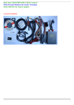
DuraWatt DS12VD
140-Watt DC-DC 12 Volt Power Supply
Short Form User Manual
Version 1.0
Table of Contents
1.
Getting Started......................................................................................................................................1
1.1. Introduction...........................................................................................................................................1
1.2.
1.3.
1.4.
1.5.
1.6.
1.7.
1.8.
1.9.
2.
Specifications .......................................................................................................................................5
2.1.
2.2.
4.
Product Photo ...............................................................................................................................2
Block Diagram...............................................................................................................................2
Included Contents and Optional Accessories................................................................................2
Recommended Additional Supplies ..............................................................................................3
Recommended Tools ....................................................................................................................3
Connection Overview Diagram .....................................................................................................3
Precautions and Warnings ............................................................................................................3
Detailed Connection Diagram .......................................................................................................4
Electrical .......................................................................................................................................5
Mechanical....................................................................................................................................5
Mpegbox.com Limited Warranty .........................................................................................................6
1. Getting Started
1.1.
Introduction
Thank you for purchasing a DSX12VD Automotive 12 Volt Power Supply. Please take some time to read
through this manual before attempting to use this product.
The DSX12VD is the optimal solution for providing a stable and clean 12-volt power source to a variety of
electronic devices in an automobile. A stable 12-volts is achieved by the buck-boost topology which allows the
input to be above or below the output. The DSX12VD provides a stable 12-volts even if the input has dips,
spikes, or noise. This makes it optimal for powering 12-volt computers intended for indoor use. These
computers typically use an AC-DC converter that puts out a stable 12-volts (i.e. + - 10%). Automotive 12-volt
power systems do put out 12 volts, however the drain from motors, heaters, headlights, etc. cause the voltage
to vary outside the +- 5% or +-10% required by sensitive computing equipment. A voltage range of 8-16 volts
is not uncommon in a 12-volt automotive system which is effectively 12-volts +-50%. Subjecting electronic
devices to voltage ranges this far outside their specification can at best cause erratic behavior, and at worst
cause failure or fire.
The DSX12VD has advanced microprocessor control enabling features such as Startup/Shutdown
Sequencing, Low Voltage Battery Protection, and Temperature Protection. Features also include Serial Port
Control, Diagnostics, and Upgradeability. Desktop computer motherboards are typically not designed to work
in automotive environments, the design and engineering that went into the DSX12VD makes every attempt to
compensate for this. Having purchased a DSX12VD, you will rest assured that you’ve invested in a flexible
product that can grow and expand with your automotive computing system.
DSX12VD Manual
Copyright 2006 Mpegbox.com
Page 1 of 6
1.2.
Product Photo
1.3.
Block Diagram
DSX12VD 140W DC-DC POWER SUPPLY
Chassis Ground (GND)
12 Volts In (VIN) J8
Supply
Protection
Accessory In (ACC)
Temp.
Sensor
12V to 12V
Power
Supply
Control
+12V
Monitoring
Adjust
POTs
Communication Port
(Requires RS-232 or USB
Translator)
1.4.
J2
J10
Molex-4p
J6
0.25" Spade
J1
Microcontroller
Status
LED
JP1
12V FAN
MotherBoard Switch
Computer On Sense
Advanced Options
Included Contents and Optional Accessories
Included:
1 : DSX12VD 140 Watt 12V Power Supply
1 : 12" 4-pin ATX 12V Power Cable (CPU Power Cable)
2 : 0.1" Shunt Jumpers
1 : 24" 2-pin to 2-pin Mother Board Power Switch Cable
3 : Insolated Terminal Ring Crimp/Solder Connectors 12-10AWG
Optional:
• Acroname Serial Port Adapter
• Acroname USB Serial Adapter
DSX12VD Manual
PN:S13-SERIAL-INT-CONN
PN:S19-USB-SERIAL-INT-CONN
Copyright 2006 Mpegbox.com
Page 2 of 6
Installation Guide
1.5.
•
•
•
•
•
•
1.6.
•
•
•
1.7.
Recommended Additional Supplies
12 AWG Hookup Wire for Vin and Gnd Inputs (Minimum Recommended Gauge)
12-24 AWG Hookup Wire for Acc Input (Very little current flows through this wire)
Mounting Screws (4-40 or 6-32)
Mounting Standoffs (Optional)
Power Supply Cooling Fan (or assure adequate airflow over the DSX12VD)
Custom Enclosure
Recommended Tools
Soldering Iron and or Crimp Tool (Secure Input Power Connections)
Philips Jewelers Screwdrivers (for P1 P2 Adjustment Pots)
Philips Head Screwdriver (for Mounting Screws and J8 Terminal Screws)
Connection Overview Diagram
DSX12VD 140W DC-DC POWER SUPPLY
Computer
Motherboard
J8
GND
VIN
Supply
Protection
ACC
Temp.
Sensor
12V to12V
Power
Supply
Control
Monitoring
Adjust
POTs
Translator
Serial Diagnostics
and Control
J2
+12V
4-Pin
+12V
J10
J6
Power
Supply Fan
J1
Microcontroller
Status
LED
JP1
MB Power Switch
1.8.
Precautions and Warnings
Operating a personal computer in a motor vehicle can be dangerous. Improper use or negligence can
result in damage and or loss of life to self and others. Safety precautions must be considered when
operating a personal computer in a motor vehicle. Displays must not be distracting to the driver and should
not display motion video or otherwise distracting content. Check with the local government in your area for
laws and guidelines regarding the use of potentially distracting electronic devices in motor vehicles.
Mpegbox.com and the people responsible for its content shall not be held responsible for loss or damage
as a result of the content, procedures, or the use of the product/s outlined in this manual. A personal
computer used in a motor vehicle should only be operated as a personal computer when then vehicle is
not moving. Use this product at your own risk. Various safety features are built into this product and any
attempt to override them will void any warranties and may cause increased risk of damage to persons or
property.
DSX12VD Manual
Copyright 2006 Mpegbox.com
Page 3 of 6
1.9.
Detailed Connection Diagram
P1 P2
J1
J6
J10
D8
F1
J2
J8
JP1
Power Input
J8
Gnd:
Vin:
Acc:
F1
Input Fuse:
Power Output
J6
Vout:
J10
Vout:
J1
FAN:
Control
JP1
Pins G1, G2:
P1*
P2*
D8
J2
Ground Input, connect to the chassis or the (–) battery terminal
+12 Volts Input, connect directly to the (+) battery terminal
Accessory Input, Connect to a switched +12 volt supply wire (ignition or fuse box)
15-Amp mini-automotive fuse (yellow)
0.25” Faston Spade 12-volt output connection
4-pin 12-volt output connection (Molex: 39-31-0040)
Connects to a 12 Volt 3-pin fan to cool the DSX12VD
Pins F1, F2:
Pins E1, E2:
Pins D1, D2:
Pins C1, C2:
Pins B1, B2:
Pins A1, A2:
Connects to Motherboard Power Switch Header (G2=Signal +, G1 Signal -)
Aux Connection (for Amp Enable or Slave Power Supply (F1= Open Collector)
On_Sense (connect to any 5 volt line to detect when computer is on/off)
User Switch (will zero countdown timer when shorted)
User1 (RESERVED)
User0 (RESERVED)
A1=+5V, A2=nReset (RESERVED)
Countdown Adj:
Low Voltage Adj:
LED indicator:
Serial Port:
In Basic Mode, clockwise rotation adds time to the Countdown Timer (0-20m)
In Basic Mode, clockwise rotation raises the low voltage threshold (10V-12V)
Indicates Operation, Timer States, and Faults
Enables Advanced Modes, field upgrades, and diagnostics
*Note: Do Not Over-Turn P1 and P2, only 270 degrees is available
DSX12VD Manual
Copyright 2006 Mpegbox.com
Page 4 of 6
2. Specifications
2.1.
Electrical
Electrical Specifications:
Input Voltage (Operating)
Input Voltage (Full Load)
Input Current
Output Power
No Load Operating Current
Sleep Current (All Rails Off)
Efficiency
6-24 Volts Non-Regulated
8-16 Volts Non-Regulated
15A (15A mini-blade fuse)
140 Watts Max
< 70mA
< 4mA
> 95%
Individual Supply Outputs
12.0 Volts +/- 2%
Max Output Current
12 Amps Nominal, 15 Amps Peak
Electraical I/O Specifications
ACC Input Threshold
ACC Input Impedance
MB Power Switch Output Drive
On_Sense Pull Up
On_Sense Detect Voltage
AUX Output Drive
User Switch Pull-Up Drive
Serial Port Rx/Tx
Low = < 4V, High = >7V (30V Max)
100k Ohms
Open Collector, 50mA Max
~10k Ohms to 5 volts.
Low = < 0.7V, High = >2V (5V Max)
Open Collector, 50mA Max
10k Ohms to 5V
Low = < 0.7V, High = >2V (5V Max)
Supervisor Specifications (Basic Mode)
P1 - Countdown Timer Range
0-20 minutes (10 minutes default)
P2 - Low Voltage Cutout Range
10-12 volts (11 volts default)
Operating Temperature Range
-40 to +90 degrees Celsius
Controlled Temperature Range
-10 to +55 degrees Celsius
MB Turn On Delay
1 second
MB Power Switch Duration
1 second
Max Shutdown Timer Range
90 seconds
2.2.
Mechanical
Mechanical Specification
Board Dimmensions
Mounting hole corridnates (in)
Mounting hole size (in)
Board Thickness (in)
DSX12VD Manual
4.38"L x 1.9"W x 1.0"H
(0.2, 0.2) (0.2, 3.475) (1.7, 3.475) (1.7, 0.2)
0.125
0.062
Copyright 2006 Mpegbox.com
Page 5 of 6
3. Troubleshooting
Please visit the www.mpegbox.com support forums for troubleshooting tips.
4. Mpegbox.com Limited Warranty
The DSX12VD Power Supply carries a Limited Warranty for the Period of 1 year from the date of
purchase. Mpegbox.com warrants its products to be free from defects in workmanship and materials for a
period of one (1) year from the date of purchase, Mpegbox.com will repair or replace the unit at our option,
without charge for parts or labor. After the period of one year, the customer will be responsible for all charges
for parts and labor. This limited warranty is extended only to the original purchaser. It does not cover any
equipment connected to the DSX12VD or other consumable parts; transportation costs, or any damage
incurred in transit. This warranty will become void if the serial number identification has be wholly or partially
removed or altered. Repair ore replacement under the terms and conditions of this warranty does not extent
the term of this warranty. Any modification of the temperature control system parameters or modifications to
the mechanical or electrical structure of this product will void this limited warranty.
A Return Material Authorization (RMA) must be obtained prior to returning the product by emailing
[email protected]. The RMA number must be marked on the outside of the shipping container and copy
of a sales receipt or invoice must be included. Please include a brief description of the symptoms, your name,
address, email and any other relevant instructions. Returns must be shipped prepaid in a static safe with
adequate padding before returning to Mpegbox.com
DSX12VD Manual
Copyright 2006 Mpegbox.com
Page 6 of 6