1
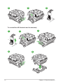
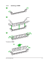
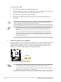
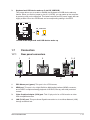
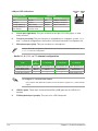
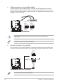
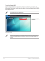
Motherboard
A55BM-E/BR
E8866
First Edition
December 2013
Copyright © 2013 ASUSTeK COMPUTER INC. All Rights Reserved.
No part of this manual, including the products and software described in it, may be reproduced,
transmitted, transcribed, stored in a retrieval system, or translated into any language in any form or by any
means, except documentation kept by the purchaser for backup purposes, without the express written
permission of ASUSTeK COMPUTER INC. (“ASUS”).
Product warranty or service will not be extended if: (1) the product is repaired, modified or altered, unless
such repair, modification of alteration is authorized in writing by ASUS; or (2) the serial number of the
product is defaced or missing.
ASUS PROVIDES THIS MANUAL “AS IS” WITHOUT WARRANTY OF ANY KIND, EITHER EXPRESS
OR IMPLIED, INCLUDING BUT NOT LIMITED TO THE IMPLIED WARRANTIES OR CONDITIONS OF
MERCHANTABILITY OR FITNESS FOR A PARTICULAR PURPOSE. IN NO EVENT SHALL ASUS, ITS
DIRECTORS, OFFICERS, EMPLOYEES OR AGENTS BE LIABLE FOR ANY INDIRECT, SPECIAL,
INCIDENTAL, OR CONSEQUENTIAL DAMAGES (INCLUDING DAMAGES FOR LOSS OF PROFITS,
LOSS OF BUSINESS, LOSS OF USE OR DATA, INTERRUPTION OF BUSINESS AND THE LIKE),
EVEN IF ASUS HAS BEEN ADVISED OF THE POSSIBILITY OF SUCH DAMAGES ARISING FROM ANY
DEFECT OR ERROR IN THIS MANUAL OR PRODUCT.
SPECIFICATIONS AND INFORMATION CONTAINED IN THIS MANUAL ARE FURNISHED FOR
INFORMATIONAL USE ONLY, AND ARE SUBJECT TO CHANGE AT ANY TIME WITHOUT NOTICE,
AND SHOULD NOT BE CONSTRUED AS A COMMITMENT BY ASUS. ASUS ASSUMES NO
RESPONSIBILITY OR LIABILITY FOR ANY ERRORS OR INACCURACIES THAT MAY APPEAR IN THIS
MANUAL, INCLUDING THE PRODUCTS AND SOFTWARE DESCRIBED IN IT.
Products and corporate names appearing in this manual may or may not be registered trademarks or
copyrights of their respective companies, and are used only for identification or explanation and to the
owners’ benefit, without intent to infringe.
Offer to Provide Source Code of Certain Software
This product contains copyrighted software that is licensed under the General Public License (“GPL”),
under the Lesser General Public License Version (“LGPL”) and/or other Free Open Source Software
Licenses. Such software in this product is distributed without any warranty to the extent permitted by the
applicable law. Copies of these licenses are included in this product.
Where the applicable license entitles you to the source code of such software and/or other additional data,
you may obtain it for a period of three years after our last shipment of the product, either
(1) for free by downloading it from http://support.asus.com/download
or
(2) for the cost of reproduction and shipment, which is dependent on the preferred carrier and the location
where you want to have it shipped to, by sending a request to:
ASUSTeK Computer Inc.
Legal Compliance Dept.
15 Li Te Rd.,
Beitou, Taipei 112
Taiwan
In your request please provide the name, model number and version, as stated in the About Box of the
product for which you wish to obtain the corresponding source code and your contact details so that we
can coordinate the terms and cost of shipment with you.
The source code will be distributed WITHOUT ANY WARRANTY and licensed under the same license as
the corresponding binary/object code.
This offer is valid to anyone in receipt of this information.
ASUSTeK is eager to duly provide complete source code as required under various Free Open Source
Software licenses. If however you encounter any problems in obtaining the full corresponding source
code we would be much obliged if you give us a notification to the email address [email protected], stating
the product and describing the problem (please DO NOT send large attachments such as source code
archives, etc. to this email address).
ii
Contents
Safety information....................................................................................................... iv
About this guide.......................................................................................................... iv
Package contents........................................................................................................ vi
A55BM-E/BR specifications summary...................................................................... vi
Chapter 1:
Product introduction
1.1
Before you proceed....................................................................................... 1-1
1.2
Motherboard overview.................................................................................. 1-2
1.3
Accelerated Processing Unit (APU)............................................................. 1-4
1.4
System memory............................................................................................. 1-7
1.5
Expansion slots........................................................................................... 1-10
1.6
Jumpers....................................................................................................... 1-11
1.7
Connectors................................................................................................... 1-13
1.8
Software support......................................................................................... 1-21
Chapter 2:
BIOS information
2.1
Managing and updating your BIOS.............................................................. 2-1
2.2
BIOS setup program...................................................................................... 2-5
2.3
My Favorites.................................................................................................. 2-9
2.4
Main menu.................................................................................................... 2-10
2.5
Ai Tweaker menu......................................................................................... 2-11
2.6
Advanced menu........................................................................................... 2-12
2.7
Monitor menu............................................................................................... 2-12
2.8
Boot menu.................................................................................................... 2-13
2.9
Tools menu................................................................................................... 2-14
2.10 Exit menu..................................................................................................... 2-14
Appendices
Notices...................................................................................................................... A-1
ASUS contact information....................................................................................... A-4
iii
Safety information
Electrical safety
•
To prevent electrical shock hazard, disconnect the power cable from the electrical outlet
before relocating the system.
•
When adding or removing devices to or from the system, ensure that the power cables
for the devices are unplugged before the signal cables are connected. If possible,
disconnect all power cables from the existing system before you add a device.
•
Before connecting or removing signal cables from the motherboard, ensure that all
power cables are unplugged.
•
Seek professional assistance before using an adapter or extension cord. These devices
could interrupt the grounding circuit.
•
Ensure that your power supply is set to the correct voltage in your area. If you are not
sure about the voltage of the electrical outlet you are using, contact your local power
company.
•
If the power supply is broken, do not try to fix it by yourself. Contact a qualified service
technician or your retailer.
Operation safety
•
Before installing the motherboard and adding devices on it, carefully read all the manuals
that came with the package.
•
Before using the product, ensure all cables are correctly connected and the power
cables are not damaged. If you detect any damage, contact your dealer immediately.
•
To avoid short circuits, keep paper clips, screws, and staples away from connectors,
slots, sockets and circuitry.
•
Avoid dust, humidity, and temperature extremes. Do not place the product in any area
where it may become wet.
•
Place the product on a stable surface.
•
If you encounter technical problems with the product, contact a qualified service
technician or your retailer.
About this guide
This user guide contains the information you need when installing and configuring the
motherboard.
How this guide is organized
This guide contains the following parts:
•
Chapter 1: Product introduction
This chapter describes the features of the motherboard and the new technology it
supports.
•
Chapter 2: BIOS information
This chapter tells how to change system settings through the BIOS Setup menus.
Detailed descriptions of the BIOS parameters are also provided.
iv
Where to find more information
Refer to the following sources for additional information and for product and software
updates.
1.
ASUS websites
The ASUS website provides updated information on ASUS hardware and software
products. Refer to the ASUS contact information.
2.
Optional documentation
Your product package may include optional documentation, such as warranty flyers,
that may have been added by your dealer. These documents are not part of the
standard package.
Conventions used in this guide
To ensure that you perform certain tasks properly, take note of the following symbols used
throughout this manual.
DANGER/WARNING: Information to prevent injury to yourself when trying to
complete a task.
CAUTION: Information to prevent damage to the components when trying to
complete a task
IMPORTANT: Instructions that you MUST follow to complete a task..
NOTE: Tips and additional information to help you complete a task.
Typography
Bold text
Indicates a menu or an item to select.
Italics
Used to emphasize a word or a phrase.
<Key>
Keys enclosed in the less-than and greater-than sign
means that you must press the enclosed key.
Example: <Enter> means that you must press the Enter or
Return key.
<Key1> + <Key2> + <Key3>
If you must press two or more keys simultaneously, the key
names are linked with a plus sign (+).
Package contents
Check your motherboard package for the following items.
Motherboard
ASUS A55BM-E/BR motherboard
Cables
2 x Serial ATA 3.0 Gb/s cables
Accessories
1 x I/O Shield
Application DVD
Support DVD
Documentation
User Guide
If any of the above items is damaged or missing, contact your retailer.
A55BM-E/BR specifications summary
CPU
AMD® FM2+ Socket for AMD® A-Series/Athlon™ Series processors
AMD® Turbo Core Technology 3.0 support
Supports APU up to 4 cores
• Refer to www.asus.com for the AMD® APU support list.
Chipset
AMD® A55 FCH (Hudson D2)
Memory
2 x DDR3 DIMM, max. 32GB, DDR3 2133* / 1866 / 1600 / 1333 MHz, nonECC un-buffered memory
Dual-channel memory architecture
Supports AMD Memory Profile (AMP) memory
* Hyper DIMM support is subject to the physical characteristics of individual
CPUs.
• The maximum 32GB memory capacity can be supported with 16GB or above
DIMMs. ASUS will update the memory QVL once the DIMMs are available in the
market.
• Refer to www.asus.com for the latest Memory QVL (Qualified Vendors List).
• When you install a total memory of 4GB capacity or more, Windows® 32-bit
operating system may only recognize less than 3GB. We recommend a
maximum of 3GB system memory if you are using a Windows® 32-bit operating
system.
Graphics
Integrated AMD® Radeon™ HD 8000 / 7000 Series Graphics in the ASeries APU
Multi-VGA output support: DVI-D and D-Sub
Supports HDMI with max. resolution 4096x2160@60Hz
Supports D-Sub with max. resolution 1920x1600@60Hz
AMD® Dual Graphics technology support*
Maximum shared memory of 2G
Supports AMD® Dual Graphics technology
* Refer to http://www.amd.com/us/products/technologies/dual-graphics/
Pages/dual-graphics.aspx#3 for the discrete GPUs which support Dual Graphics
technology.
Expansion slots
1 x PCIe 3.0/2.0 x16 slot*
1 x PCIe 2.0 x1 slot
1 x PCI slot
• PCIe 3.0 is supported by FM2+ processors only.
(continued on the next page)
vi
A55BM-E/BR specifications summary
Storage / RAID
AMD® A55 FCH:
- 6 x Serial ATA 3.0Gb/s connectors (dark brown) support RAID 0, RAID 1,
RAID 10, and JBOD configurations
LAN
Realtek® 8111G Gigabit LAN controller
Audio
Realtek® ALC887-VD 8-channel High Definition Audio CODEC
• Use a chassis with HD audio module in the front panel to support a 7.1-channel
audio output.
USB
AMD® A55 FCH:
- 8 x USB 2.0/1.1 ports (4 ports at the mid-board, 4 ports at the back panel)
ASUS unique
features
ASUS 5X Protection
- ASUS motherboards safeguard your PC with 5X Protection: DIGI+VRM,
DRAM Fuse, ESD Guards, High-Quality 5K-Hour Solid Capacitors, and
Stainless Steel Back I/O to ensure the best quality, reliability, and durability
ASUS Digi+ VRM
- ASUS DIGI+ VRM: Digital Power Design for the APU
- ASUS 3+1 Phase Power Design
ASUS DRAM Fuse
- Enhanced DRAM overcurrent protection and short circuit damage prevention
ASUS ESD Guards
- Strong ESD protection for extended component lifespan
ASUS High-Quality 5K-Hour Solid Capacitors
- 2.5x Longer lifespan with excellent durability
ASUS Stainless Steel Back I/O
- 3x More durable corrosion-resistant coating
ASUS Exclusive Features
- EPU
- Network iControl
- AI Suite 3
- AI Charger
- Anti-Surge
ASUS Quiet Thermal Solutions
- ASUS Fanless Design: Stylish heatsink solution
- ASUS Fan Xpert
- ASUS UEFI BIOS
ASUS EZ DIY
- ASUS CrashFree BIOS 3
- ASUS EZ Flash 2
- ASUS MyLogo 2
(continued on the next page)
vii
A55BM-E/BR specifications summary
Back Panel I/O
ports
1 x PS/2 mouse port (green)
1 x PS/2 keyboard port (purple)
1 x HDMI port
1 x VGA port
1 x LAN (RJ-45) port
4 x USB 2.0/1.1 ports
8-channel audio I/O ports (3-jack)
Internal I/O
connectors
2 x USB 2.0 connectors support additional 4 USB 2.0 ports
6 x SATA 3.0Gb/s connectors
1 x COM connector
1 x LPT connector
1 x System panel connector
1 x Internal Speaker connector
1 x 4-pin CPU fan connector
1 x S/PDIF output connector
1 x 4-pin Chassis fan connector
1 x Front panel audio connector
1 x 24-pin EATX power connector
1 x 4-pin ATX 12V power connector
BIOS
64 Mb Flash ROM, UEFI AMI BIOS, PnP, DMI 2.0, WfM 2.0, SM BIOS 2.6,
ACPI 2.0a, Multi-language BIOS, ASUS CrashFree BIOS 3, F12 Printscreen
function, F3 Shortcut function, and ASUS DRAM SPD (Serial Presence
Detect) memory information
Support DVD
Drivers
ASUS Update
ASUS utilities
Anti-Virus software (OEM version)
Operating System
Support
Windows® 8.1 / Windows® 8.1 64-bit
Windows® 8 / Windows® 8 64-bit
Windows® 7 / Windows® 7 64-bit
Windows® Vista / Windows® Vista 64-bit
Windows® XP
Form factor
uATX form factor: 9.1 in x 7.2 in (23.1 cm x 18.3 cm)
Specifications are subject to change without notice.
viii
Product introduction
1.1
Before you proceed
1
Take note of the following precautions before you install motherboard components or change
any motherboard settings.
•
Unplug the power cord from the wall socket before touching any component.
•
Before handling components, use a grounded wrist strap or touch a safely grounded
object or a metal object, such as the power supply case, to avoid damaging them due
to static electricity.
•
Hold components by the edges to avoid touching the ICs on them.
•
Whenever you uninstall any component, place it on a grounded antistatic pad or in the
bag that came with the component.
•
Before you install or remove any component, ensure that the ATX power supply is
switched off or the power cord is detached from the power supply. Failure to do so
may cause severe damage to the motherboard, peripherals, or components.
ASUS A55BM-E/BR
1-1
1.2
Motherboard overview
Before you install the motherboard, study the configuration of your chassis to ensure that the
motherboard fits into it.
Ensure that you unplug the power cord before installing or removing the motherboard.
Failure to do so can cause you physical injury and damage motherboard components.
1.2.1
Placement direction
When installing the motherboard, ensure that you place it into the chassis in the correct
orientation. The edge with external ports goes to the rear part of the chassis as indicated in
the image below.
1.2.2
Screw holes
Place six screws into the holes indicated by circles to secure the motherboard to the chassis.
Do not overtighten the screws! Doing so can damage the motherboard.
Place this side towards
the rear of the chassis
A55BM-E/BR
1-2
Chapter 1: Product introduction
1.2.3
Motherboard layout
1
2
3
4
5
18.3cm(7.2in)
KBMS
CPU_FAN
DIGI
+VRM
ATX12V
CHA_FAN
KB_USBWB
AUDIO
23.6cm(9.1in)
2
A55BM-E/BR
AMD®
A55
BATTERY
PCIEX1_1
Super
I/O
SATA3G_6
PCIEX16
SPEAKER
F_PANEL
PCI1
ALC
887
USBPWF
SATA3G_5
RTL
8111G
SATA3G_4
LAN_USB12
EATXPWR
USB1112
DDR3 DIMM_B1 (64bit, 240-pin module)
DDR3 DIMM_A1 (64bit, 240-pin module)
SOCKET FM2+
VGA
HDMI
64Mb
BIOS
CLRTC
SPDIF_OUT
USB56
LPT
AAFP
USB34
SATA3G_1
SATA3G_2
SATA3G_3
6
7
8
9
COM
15
14 13
12
11
10
7
Connectors/Jumpers/Slots/LED
Page
1. Keyboard and USB device wake up (3-pin KB_USBPWB)
2. ATX power connectors (24-pin EATXPWR, 4-pin ATX12V)
3. AMD FM2+ socket
4. CPU and chassis fan connectors (4-pin CPU_FAN and 4-pin CHA_FAN)
5. DDR3 DIMM slots
6. Speaker connector (4-pin SPEAKER)
7. SATA 3.0Gb/s connectors (7-pin SATA3G_1~6)
8. System panel connector (10-1 pin F_PANEL)
9. Clear RTC RAM (3-pin CLRTC)
10. USB 2.0 connectors (10-1 pin USB34, USB56)
11. USB device wake-up (3-pin USBPWF)
12. LPT connector (26-1 pin LPT)
13. Digital audio connector (4-1 pin SPDIF_OUT)
14. Serial port connector (10-1 pin COM)
15. Front panel audio connector (10-1 pin AAFP)
ASUS A55BM-E/BR
1-3
1.3
Accelerated Processing Unit (APU)
This motherboard comes with an FM2+ socket designed for AMD® A-series accelerated
processors with AMD® Radeon™ HD 7000/8000 series graphics.
A55BM-E/BR
A55BM-E/BR CPU socket FM2+
Ensure that you use an APU designed for the FM2+ socket. The APU fits in only one
correct orientation. DO NOT force the APU into the socket to prevent bending the pins and
damaging the APU!
1.3.1
1
1-4
Installing the APU
2
Chapter 1: Product introduction
3
1.3.2
4
APU heatsink and fan assembly installation
Apply the Thermal Interface Material
to the APU heatsink and APU before
you install the heatsink and fan if
necessary.
To install the APU heatsink and fan assembly
1
ASUS A55BM-E/BR
2
1-5
3
4
5
To uninstall the APU heatsink and fan assembly
1
4
1-6
3
2
5
Chapter 1: Product introduction
1.4
System memory
1.4.1
Overview
The motherboard comes with two Double Data Rate 3 (DDR3) Dual Inline Memory Modules
(DIMM) sockets.
A DDR3 module has the same physical dimensions as a DDR2 DIMM but is notched
differently to prevent installation on a DDR2 DIMM socket. DDR3 modules are developed for
better performance with less power consumption.
DIMM_A1
DIMM_B1
The figure illustrates the location of the DDR3 DIMM sockets:
Channel
A55BM-E/BR
Sockets
Channel A
DIMM_A1
Channel B
DIMM_B1
A55BM-E/BR 240-pin DDR3 DIMM sockets
ASUS A55BM-E/BR
1-7
1.4.2
Memory configurations
You may install 1GB, 2GB, 4GB, and 8GB unbuffered non‑ECC DDR3 DIMMs into the DIMM
sockets.
1-8
•
You may install varying memory sizes in Channel A and Channel B. The system maps
the total size of the lower-sized channel for the dual-channel configuration. Any excess
memory from the higher-sized channel is then mapped for single-channel operation.
•
Always install DIMMs with the same CAS latency. For optimal compatibility, we
recommend that you install memory modules of the same version or date code (D/C)
from the same vendor. Check with the retailer to get the correct memory modules.
•
Due to the memory address limitation on 32-bit Windows® OS, when you install 4GB
or more memory on the motherboard, the actual usable memory for the OS can be
about 3GB or less. For effective use of memory, we recommend that you do any of the
following:
-
-
•
This motherboard does not support DIMMs made up of 512Mb (64MB) chips or less.
•
The maximum 32GB memory capacity can be supported with 16GB or above DIMMs.
ASUS will update the memory QVL once the DIMMs are available in the market.
•
The default memory operation frequency is dependent on its Serial Presence Detect
(SPD), which is the standard way of accessing information from a memory module.
Under the default state, some memory modules for overclocking may operate at a
lower frequency than the vendor-marked value. To operate at the vendor-marked
or at a higher frequency, refer to section 2.5 Ai Tweaker menu for manual memory
frequency adjustment.
•
For system stability, use a more efficient memory cooling system to support a full
memory load (2 DIMMs) or overclocking condition.
•
Refer to www.asus.com for the latest Memory QVL (Qualified Vendors List).
Install a maximum of 3GB system memory if you are using a 32-bit Windows® OS.
Use a 64-bit Windows® OS if you want to install 4GB or more memory on the motherboard.
Chapter 1: Product introduction
1.4.3
Installing a DIMM
1
2
3
To remove a DIMM
B
A
ASUS A55BM-E/BR
1-9
1.5
Expansion slots
In the future, you may need to install expansion cards. The following sub‑sections describe
the slots and the expansion cards that they support.
Unplug the power cord before adding or removing expansion cards. Failure to do so may
cause you physical injury and damage motherboard components.
1.5.1
Installing an expansion card
To install an expansion card:
1.
Before installing the expansion card, read the documentation that came with it and
make the necessary hardware settings for the card.
2.
Remove the system unit cover (if your motherboard is already installed in a chassis).
3.
Remove the bracket opposite the slot that you intend to use. Keep the screw for later
use.
4.
Align the card connector with the slot and press firmly until the card is completely
seated on the slot.
5.
Secure the card to the chassis with the screw you removed earlier.
6.
Replace the system cover.
1.5.2
Configuring an expansion card
After installing the expansion card, configure it by adjusting the software settings.
1.
Turn on the system and change the necessary BIOS settings, if any. See Chapter 2 for
information on BIOS setup.
2.
Assign an IRQ to the card.
3.
Install the software drivers for the expansion card.
When using PCI cards on shared slots, ensure that the drivers support “Share IRQ” or that
the cards do not need IRQ assignments. Otherwise, conflicts will arise between the two PCI
groups, making the system unstable and the card inoperable.
1.5.3
PCI slot
The PCI slot supports cards such as a LAN card, SCSI card, USB card, and other cards that
comply with PCI specifications.
1-10
Chapter 1: Product introduction
1.5.4
PCI Express x1 slot
This motherboard supports PCI Express 2.0 x1 network cards, SCSI cards, and other cards
that comply with the PCI Express specifications.
1.5.5
PCI Express x16 slot
This motherboard supports one PCI Express 3.0/2.0 x16 graphics cards that comply with the
PCI Express specifications.
IRQ assignments for this motherboard
A
B
C
D
E
F
G
H
PCIEx16_1
–
–
shared
–
–
–
–
–
PCIEx1_1
shared
–
–
–
–
–
–
–
PCI1 slot
–
–
–
–
shared
–
–
–
Realtek LAN controller
–
–
shared
–
-
–
–
–
shared
–
–
–
–
–
–
–
SATA controller
–
–
–
shared
–
–
–
–
On Chip USB EHCI 1/2/3
–
shared
–
–
–
–
–
–
On Chip USB OHCI 1/2/3/4
–
–
shared
–
–
–
–
–
HD audio
1.6
Jumpers
Clear RTC RAM (3-pin CLRTC)
This jumper allows you to clear the Real Time Clock (RTC) RAM in CMOS. You can
clear the CMOS memory of date, time, and system setup parameters by erasing
the CMOS RTC RAM data. The onboard button cell battery powers the RAM data in
CMOS, which include system setup information such as system passwords.
A55BM-E/BR
CLRTC
1
2
2
Normal
(Default)
Clear RTC
3
A55BM-E/BR Clear RTC RAM
ASUS A55BM-E/BR
1-11
To erase the RTC RAM:
1.
Turn OFF the computer and unplug the power cord.
2.
Move the jumper cap from pins 1-2 (default) to pins 2-3. Keep the cap on pins 2-3
for about 5-10 seconds, then move the cap back to pins 1-2.
3.
Plug the power cord and turn ON the computer.
4.
Hold down the <Del> key during the boot process and enter BIOS setup to reenter data.
Except when clearing the RTC RAM, never remove the cap on CLRTC jumper default
position. Removing the cap will cause system boot failure!
2.
•
If the steps above do not help, remove the onboard battery and move the jumper
again to clear the CMOS RTC RAM data. After clearing the CMOS, reinstall the
battery.
•
You do not need to clear the RTC when the system hangs due to overclocking. For
system failure due to overclocking, use the CPU Parameter Recall (C.P.R.) feature.
Shut down and reboot the system, then the BIOS automatically resets parameter
settings to default values.
USB device wake-up (3-pin USBPWF)
Set these jumpers to +5V to wake up the computer from S1 sleep mode (CPU stopped,
DRAM refreshed, system running in low power mode) using the connected USB
devices. Set to +5VSB to wake up from S3 and S4 sleep modes (no power to CPU,
DRAM in slow refresh, power supply in reduced power mode).
USBPWF
A55BM-E/BR
1
2
+5V
(Default)
2 3
+5VSB
A55BM-E/BR USB device wake up
1-12
•
The USB device wake-up feature requires a power supply that can provide 500mA on
the +5VSB lead for each USB port; otherwise, the system would not power up.
•
The total current consumed must NOT exceed the power supply capability (+5VSB)
whether under normal condition or in sleep mode.
Chapter 1: Product introduction
3.
Keyboard and USB device wake up (3-pin KB_USBPWB)
This jumper allows you to enable or disable the keyboard and USB device wake-up
feature. When you set this jumper to pins 2-3 (+5VSB), you can wake up the computer
by pressing a key on the keyboard. This feature requires an ATX power supply that can
supply at least 1A on the +5VSB lead, and a corresponding setting in the BIOS.
1
A55BM-E/BR
2
2
3
KB_USBPWB
+5V
+5VSB
(Default)
A55BM-E/BR Keyboard and USB device wake up
1.7
Connectors
1.7.1
Rear panel connectors
1
2
3
9
4
8
5 6
7
1.
PS/2 Mouse port (green). This port is for a PS/2 mouse.
2.
HDMI port. This port is for a High-Definition Multimedia Interface (HDMI) connector,
and is HDCP compliant allowing playback of HD DVD, Blu-ray, and other protected
content.
3.
Video Graphics Adapter (VGA) port. This 15-pin port is for a VGA monitor or other
VGA-compatible devices.
4.
LAN (RJ-45) port. This port allows Gigabit connection to a Local Area Network (LAN)
through a network hub.
ASUS A55BM-E/BR
1-13
LAN port LED indications
Activity/Link LED
Status
Off
Orange
Orange (Blinking)
Orange (Blinking
then steady)
Description
No link
Linked
Data activity
Ready to wake up
from S5 mode
ACT/LINK SPEED
LED
LED
Speed LED
Status
Description
OFF
10Mbps connection
ORANGE 100Mbps connection
GREEN
1Gbps connection
LAN port
5.
Line In port (light blue). This port connects to the tape, CD, DVD player, or other
audio sources.
6.
Line Out port (lime). This port connects to a headphone or a speaker. In the 4.1, 5.1,
and 7.1-channel configurations, the function of this port becomes Front Speaker Out.
7.
Microphone port (pink). This port connects to a microphone.
Refer to the audio configuration table below for the function of the audio ports in 2.1, 4.1,
5.1, or 7.1-channel configuration.
Audio 2.1, 4.1, 5.1, or 7.1-channel configuration
Port
Light Blue (Rear panel)
Lime (Rear panel)
Pink (Rear panel)
Lime (Front panel)
Headset
2.1channel
Line In
Line Out
Mic In
—
4.1-channel
5.1-channel
Rear Speaker Out Rear Speaker Out
Front Speaker Out Front Speaker Out
Mic In
Bass/Center
—
—
7.1-channel
Rear Speaker Out
Front Speaker Out
Bass/Center
Side Speaker Out
To configure a 7.1-channel audio output:
1-14
Use a chassis with HD audio module in the front panel to support a 7.1-channel audio
output.
8.
USB 2.0 ports. These 4-pin Universal Serial Bus (USB) ports are for USB 2.0/1.1
devices.
9.
PS/2 Keyboard port (purple). This port is for a PS/2 keyboard.
Chapter 1: Product introduction
1.7.2
1.
Internal connectors
CPU and chassis fan connectors (4-pin CPU_FAN, and 4-pin CHA_FAN)
CHA_FAN
+5V
CHA FAN IN
CHA FAN PWR
GND
A55BM-E/BR
CPU_FAN
CPU FAN PWM
CPU FAN IN
CPU FAN PWR
GND
Connect the fan cables to the fan connectors on the motherboard, ensuring that the
black wire of each cable matches the ground pin of the connector.
A55BM-E/BR Fan connectors
DO NOT forget to connect the fan cables to the fan connectors. Insufficient air flow inside
the system may damage the motherboard components. These are not jumpers! DO NOT
place jumper caps on the fan connectors.
•
The CPU_FAN connector supports a CPU fan of maximum 2A (24 W) fan power.
•
The CPU_FAN and CHA_FAN connectors support the ASUS Fan Xpert feature.
ASUS A55BM-E/BR
1-15
2.
ATX power connectors (24-pin EATXPWR, 4-pin ATX12V)
These connectors are for an ATX power supply. The plugs from the power supply are
designed to fit these connectors in only one orientation. Find the proper orientation and
push down firmly until the connectors completely fit.
GND
GND
+12V DC
+12V DC
ATX12V
A55BM-E/BR
EATXPWR
+3 Volts
+12 Volts
+12 Volts
+5V Standby
Power OK
PIN 1
GND
+5 Volts
GND
+5 Volts
GND
+3 Volts
+3 Volts
GND
+5 Volts
+5 Volts
+5 Volts
-5 Volts
GND
GND
GND
PSON#
GND
-12 Volts
+3 Volts
PIN 1
A55BM-E/BR ATX power connectors
1-16
•
We recommend that you use an ATX 12V Specification 2.0‑compliant power supply
unit (PSU) with a minimum of 300W power rating. This PSU type has 24-pin and 4-pin
power plugs.
•
If you intend to use a PSU with 20-pin and 4-pin power plugs, ensure that the 20-pin
power plug can provide at least 15 A on +12 V and that the PSU has a minimum
power rating of 300W. The system may become unstable or may not boot up if the
power is inadequate.
•
DO NOT forget to connect the 4-pin ATX +12V power plug. Otherwise, the system will
not boot up.
•
We recommend that you use a PSU with higher power output when configuring a
system with more power-consuming devices or when you intend to install additional
devices. The system may become unstable or may not boot up if the power is
inadequate.
•
If you are uncertain about the minimum power supply requirement for your system,
refer to the Recommended Power Supply Wattage Calculator at http://support.asus.
com/PowerSupplyCalculator/PSCalculator.aspx?SLanguage=en-us for details.
Chapter 1: Product introduction
3.
Serial ATA 3.0 Gb/s connectors (7-pin SATA3G 1~6)
These connectors are for the Serial ATA 3.0 Gb/s signal cables for Serial ATA hard
disk drives and optical disc drives. If you installed Serial ATA hard disk drives, you can
create a RAID 0, RAID 1, or RAID 10 configuration through the onboard controller.
SATA3G_6
GND
RSATA_RXP6
RSATA_RXN6
GND
RSATA_TXN6
RSATA_TXP6
GND
SATA3G_5
GND
RSATA_RXP5
RSATA_RXN5
GND
RSATA_TXN5
RSATA_TXP5
GND
SATA3G_4
SATA3G_1
SATA3G_2 SATA3G_3
GND
RSATA_TXP3
RSATA_TXN3
GND
RSATA_RXN3
RSATA_RXP3
GND
GND
RSATA_TXP2
RSATA_TXN2
GND
RSATA_RXN2
RSATA_RXP2
GND
GND
RSATA_TXP1
RSATA_TXN1
GND
RSATA_RXN1
RSATA_RXP1
GND
A55BM-E/BR
GND
RSATA_RXP4
RSATA_RXN4
GND
RSATA_TXN4
RSATA_TXP4
GND
A55BM-E/BR SATA 3.0Gb/s connectors
•
These connectors are set to AHCI mode by default. If you intend to create a Serial ATA
RAID set using these connectors, set the type of the SATA connectors in the BIOS to
[RAID].
•
You must install Windows® XP Service Pack 3 or later version before using Serial
ATA hard disk drives. The Serial ATA RAID feature is available only if you are using
Windows® XP SP3 or later version.
•
When using hot-plug and NCQ, set the type of the SATA connectors in the BIOS to
[AHCI].
ASUS A55BM-E/BR
1-17
4.
System panel connector (10-1 pin PANEL)
This connector supports several chassis-mounted functions.
F_PANEL
PWR_LED+
PWR_LEDPWR
GND
+PWR LED PWR BTN
HDD_LED+
HDD_LEDGround
HWRST#
(NC)
PIN 1
A55BM-E/BR
+HDD_LED
RESET
A55BM-E/BR System panel connector
•
System power LED (2-pin PWR_LED)
This 2-pin connector is for the system power LED. Connect the chassis power LED
cable to this connector. The system power LED lights up when you turn on the system
power, and blinks when the system is in sleep mode.
•
Hard disk drive activity LED (2-pin HDD_LED)
This 2-pin connector is for the HDD Activity LED. Connect the HDD Activity LED cable
to this connector. The HDD LED lights up or flashes when data is read from or written
to the HDD.
•
ATX power button/soft-off button (2-pin PWR_BTN)
This 2-pin connector is for the system power button.
•
Reset button (2-pin RESET)
This 2-pin connector is for the chassis-mounted reset button for system reboot without
turning off the system power.
5.
Speaker connector (4-pin SPEAKER)
The 4-pin connector is for the chassis-mounted system warning speaker. The speaker
allows you to hear system beeps and warnings.
+5V
GND
GND
Speaker Out
SPEAKER
A55BM-E/BR
PIN 1
A55BM-E/BR Speaker Out Connector
1-18
Chapter 1: Product introduction
6.
Digital audio connector (4-1 pin SPDIF_OUT)
+5V
SPDIFOUT
GND
This connector is for an additional Sony/Philips Digital Interface (S/PDIF) port.
A55BM-E/BR
SPDIF_OUT
A55BM-E/BR Digital audio connector
The S/PDIF module is purchased separately.
7.
Front panel audio connector (10-1 pin AAFP)
NC
AGND
NC
NC
SENSE2_RETUR
AGND
NC
SENSE1_RETUR
This connector is for a chassis-mounted front panel audio I/O module that supports
either High Definition Audio or AC`97 audio standard. Connect one end of the front
panel audio I/O module cable to this connector.
AAFP
HD-audio-compliant
pin definition
PIN 1
MIC2
MICPWR
Line out_R
NC
Line out_L
A55BM-E/BR
PORT1 L
PORT1 R
PORT2 R
SENSE_SEND
PORT2 L
PIN 1
Legacy AC’97
compliant definition
A55BM-E/BR Front panel audio connector
•
We recommend that you connect a high-definition front panel audio module to this
connector to avail of the motherboard high-definition audio capability.
•
If you want to connect a high definition front panel audio module to this connector, set
the Front Panel Type item in the BIOS to [HD].
•
The front panel audio I/O module is purchased separately.
ASUS A55BM-E/BR
1-19
8.
USB 2.0 connectors (10-1 pin USB34, USB56)
These connectors are for USB 2.0 ports. Connect the USB module cable to any of
these connectors, then install the module to a slot opening at the back of the system
chassis. These USB connectors comply with USB 2.0 specification that supports up to
480Mbps connection speed.
USB+5V
USB_P3USB_P3+
GND
NC
USB34
USB+5V
USB_P5USB_P5+
GND
NC
USB56
PIN 1
USB+5V
USB_P4USB_P4+
GND
PIN 1
USB+5V
USB_P6USB_P6+
GND
A55BM-E/BR
A55BM-E/BR USB2.0 connectors
Never connect a 1394 cable to the USB connectors. Doing so will damage the
motherboard!
The USB 2.0 module is purchased separately.
9.
Serial port connector (10-1 pin COM)
This connector is for a serial (COM) port. Connect the serial port module cable to this
connector, then install the module to a slot opening at the back of the system chassis.
RXD
DTR
DSR
CTS
COM
DCD
TXD
GND
RTS
RI
PIN 1
A55BM-E/BR
A55BM-E/BR Serial port connectors
The COM module is purchased separately.
1-20
Chapter 1: Product introduction
10. LPT connector (26-1 pin LPT)
The LPT (Line Printing Terminal) connector supports devices such as a printer. LPT
standardizes as IEEE 1284, which is the parallel port interface on IBM PC-compatible
computers.
AFD
ERR#
INIT#
SLIN#
GND
GND
GND
GND
GND
GND
GND
GND
LPT
PIN 1
STB#
PD0
PD1
PD2
PD3
PD4
PD5
PD6
PD7
ACK#
BUSY
PE
SLCT
A55BM-E/BR
A55BM-E/BR Parallel Port Connector
1.8
Software support
1.8.1
Installing an operating system
This motherboard supports Windows® XP / Windows® Vista / 64-bit Windows® Vista
/ Windows® 7 / 64-bit Windows® 7 / Windows® 8 /64-bit Windows® 8 / Windows® 8.1 /
64-bit Windows® 8.1 Operating Systems (OS). Always install the latest OS version and
corresponding updates to maximize the features of your hardware.
1.8.2
•
Motherboard settings and hardware options vary. Refer to your OS documentation for
detailed information.
•
Ensure that you install Windows® XP Service Pack 3 or later versions before installing
the drivers for better compatibility and system stability.
•
Only motherboards installed with an AMD Trinity APU support Windows® Vista / 64bit
Windows® Vista operaing system.
Support DVD information
The Support DVD that comes with the motherboard package contains the drivers, software
applications, and utilities that you can install to avail all motherboard features.
The contents of the Support DVD are subject to change at any time without notice. Visit the
ASUS website at www.asus.com for updates.
ASUS A55BM-E/BR
1-21
To run the Support DVD
Place the Support DVD into the optical drive. If Autorun is enabled in your computer, the
DVD automatically displays the Specials screen which contains the unique features of ASUS
motherboard. Click Drivers, Utilities, Make Disk, Manual, Contact and Specials tabs to display
their respective menus.
The following screen is for reference only.
Click an icon to display
Support DVD/motherboard
information
Click an item to install
If Autorun is NOT enabled in your computer, browse the contents of the Support DVD to
locate the file ASSETUP.EXE from the BIN folder. Double-click the ASSETUP.EXE to run
the DVD.
1-22
Chapter 1: Product introduction