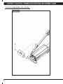
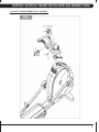
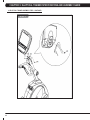
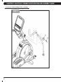
1
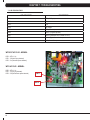
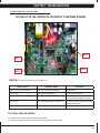
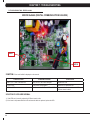
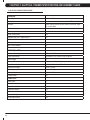
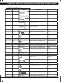
E5x-02 elliptical Trainer
S E R V IC E M AN U A l
table of contents
CHAPTER 1: Serial number location . .......................................................... 1
CHAPTER 2: Important Safety instructions
2.1
2.2
Read and Save These Instructions.............................................................................. 3
Electrical Requirements .............................................................................................. 4
CHAPTER 3: Preventative Maintenance
3.1
3.2
3.3
3.4
Recommended Cleaning Tips . ................................................................................... 5
Check for Damaged Parts .......................................................................................... 5
Care and Maintenance Instructions ............................................................................ 6
Preventative Maintenance Checklist . ......................................................................... 6
CHAPTER 4: CONSOLE overlay and workout description
4.1
4.2
4.3
4.4
4.5
4.6
4.7
Console Description . .................................................................................................. 7
Workout Setup Steps - Manual.................................................................................... 8
Workout Setup Steps - Fat Burn.................................................................................. 8
Workout Setup Steps - Training Workout.................................................................... 8
Workout Setup Steps - Cooper Fitness Test................................................................ 9
Workout Setup Steps - Target Heart Rate................................................................... 10
Workout Setup Steps - Constant Watts....................................................................... 10
CHAPTER 5: Manager MODE
5.1
5.2
Manager Mode Overview............................................................................................. 11
Manager Mode Information.......................................................................................... 12
CHAPTER 6: engineering / Service mode
6.1
Engineering / Service Mode Overview......................................................................... 13
CHAPTER 7: TROUBLESHOOTING
7.1
7.2
7.3
7.4
7.5
7.6
7.7
7.8
7.9
7.10
Electrical Diagram . ..................................................................................................... 14
Error Codes on the Console........................................................................................ 17
LCB LED Indicators..................................................................................................... 18
Troubleshooting - Display Issues................................................................................. 19
Troubleshooting - Error 0x04A0................................................................................... 20
Troubleshooting - Keypad Issues................................................................................ 21
Troubleshooting - Resistance Issues........................................................................... 22
Troubleshooting - Pedals Slipping............................................................................... 23
Troubleshooting - Noise Issues................................................................................... 23
Troubleshooting - Heart Rate Issues........................................................................... 24
CHAPTER 8: PART REPLACEMENT GUIDE
8.1
8.2
8.3
8.4
Front Disk Removal .................................................................................................... 25
Front Shroud Removal................................................................................................. 27
Lower Control Board (LCB) Replacement................................................................... 28
ECB (Electromagnetic Brake) Replacement................................................................ 29
table of contents
8.5
8.6
8.7
8.8
8.9
8.10
8.11
8.12
8.13
8.14
8.15
8.16
8.17
8.18
8.19
8.20
8.21
Belts Removal and Installation - Short Belt Run.......................................................... 30
Belts Removal and Installation - Long Belt Run.......................................................... 31
Pulley Axle Set Replacement....................................................................................... 32
Drive Axle Set Replacement........................................................................................ 33
Console Replacement.................................................................................................. 34
Console - Overlays & Keypads Replacement.............................................................. 35
Handlebar Assembly Replacement.............................................................................. 38
Heart Rate Grips Replacement.................................................................................... 39
Cup Holder Replacement............................................................................................. 40
Dual Action Handlebar Replacement........................................................................... 41
Console Mast Replacement......................................................................................... 42
Foot Pedals Replacement............................................................................................ 43
Pedal Arm Replacement.............................................................................................. 44
Crank Arm Replacement.............................................................................................. 46
Roller Replacement...................................................................................................... 49
Roller Track Replacement............................................................................................ 52
Testing the Elliptical Trainer......................................................................................... 55
CHAPTER 10: ELLIPTICAL TRAINER SPECIFICATIONS AND ASSEMBLY GUIDE
10.1
10.2
10.3 10.4 Elliptical Trainer Specifications ................................................................................... 56
Fasteners & Assembly Tools........................................................................................ 57
Elliptical Trainer Assembly Steps . .............................................................................. 58
Leveling the Elliptical Trainer....................................................................................... 67
CHAPTER 11: SOFTWARE UPGRADE PROCEDURE
11.1
iv
Software Upgrade Procedure...................................................................................... 68
Chapter 1: serial number location
1.1 SERIAL NUMBER LOCATION
1
chapter 1: serial number location
1.1 SERIAL NUMBER LOCATION - CONTINUED
console serial number location
2
Chapter 2: Important safety information
2.1 READ THESE INSTRUCTIONS
This Elliptical Trainer is intended for commercial use. To ensure
your safety and protect the equipment, read all instructions before
operating the MATRIX Elliptical Trainer.
CAUTION! If you experience chest pains, nausea, dizziness, or
shortness of breath, stop exercising immediately and consult
your physician before continuing. When using an electrical product, basic precautions should always be
followed including the following:
CAUTION! Any changes or modifications to this equipment
could void the product warranty. • A
n appliance should never be left unattended when plugged
in. Unplug the unit from the outlet when not in use and before
putting on or taking off any parts.
• T
his product must be used for its intended purpose
described in this service manual. Do not use other
attachments that are not recommend by the manufacturer.
Attachments may cause injury.
• T
o prevent electrical shock, never drop or insert any object
into any opening. • D
o not remove the console covers. Service should only be
done by an authorized service technician.
• Do not carry this unit by it’s supply cord or use the cord as a handle. • C
lose supervision is necessary when the Elliptical Trainer
is used by or near children or disable persons.
• Do not use outdoors. • D
o not operate where aerosol (spray) products are being
used or when oxygen is being administered.
• T
o disconnect, turn all controls to the off position, then
remove the plug from the outlet.
• D
o not use the equipment in any way other than designed or
intended by the manufacturer. It is imperative that all Matrix
Fitness Systems equipment is used properly to avoid injury.
• Keep hands and feet clear of moving parts at all times to avoid injury.
• Unsupervised children must be kept away from this equip
ment.
• Do not wear loose clothing while on the equipment.
3
chapter 2: Important safety instructions
2.2 ELECTRICAL REQUIREMENTS
The Matrix E5x-02 Elliptical Trainer is designed to be self powered
and does not require an external power supply source to operate.
However, these units can be AC powered if an optional power cord
is purchased. This will power the console at all times and requires
no minimum RPM for operation. These units can be daisy chained
together, up to 4 units per dedicated 15 amp circuit, using a Matrix
daisy chain cord adapter (sold separately).
For your safety and for the performance of your Matrix Elliptical
Trainer, the ground on your circuits must be non looped. Please refer
to NEC articles 210-21 and 210-23. Any alterations to the standard
Matrix power cords will void all warranties.
GROUNDING INSTRUCTIONS:
The Matrix E5x-02 Elliptical Trainer must be grounded. If it should
malfunction or break down, grounding provides a path of least
resistance for electric current to reduce the risk of electric shock.
The Elliptical Trainer is equipped with a cord having an equipment
grounding conductor and a grounding plug. The plug must be
plugged into an appropriate outlet that is properly installed and
grounded in accordance with all local codes and ordinances. If the
user does not follow these grounding instructions, the user could
void the Matrix limited warranty.
DANGER: Improper connection of the equipment grounding
conductor can result in the risk of electric shock. Check with a
qualified electrician if the user is in doubt as to whether the product
is properly grounded. Do not modify the plug provided with the
product if it will not fit the outlet, have a proper outlet installed by an
electrician
4
Chapter 3: Preventative Maintenance
3.1 RECOMMENDED CLEANING TIPS
Preventative maintenance and daily cleaning will prolong the life and
look of your MATRIX Elliptical Trainer.
Please read and follow these tips.
• P
osition the equipment away from direct sunlight. The intense UV
light can cause discoloration on plastics.
• L
ocate your equipment in an area with cool temperatures and low
humidity.
• Clean with a soft 100% cotton cloth.
• C
lean with soap and water or other non-ammonia based all purpose cleaners.
• W
ipe foot pads, handles, heart rate grips, and handlebars clean
after each use.
3.2 check for damaged parts
DO NOT use any equipment that is damaged or has worn or broken
parts. Use only replacement parts supplied by Matrix Fitness
Systems.
maintain labels and nameplates. Do not remove labels
for any reason. They contain important information. If unreadable or
missing, contact Matrix Fitness Systems for a replacement. 1-866693-4863, www.matrixfitness.com
maintain all equipment Preventative maintenance is the key
to smooth operating equipment. Equipment needs to be inspected
at regular intervals. Defective components must be replaced
immediately. Improperly working equipment must be kept out of use
until it is repaired. Ensure that any person(s) making adjustments
or performing maintenance or repair of any kind is qualified to do
so. Matrix Fitness Systems will provide service and maintenance
training at our corporate facility upon request or in the field if proper
arrangements are made.
• D
o not pour liquids directly onto your equipment. This can cause
damage to the equipment and in some cases electrocution.
• Check pedal motion and stability.
• Adjust leveling feet when equipment wobbles or rocks.
• Maintain a clean area around equipment, free from dust and dirt.
5
chapter 3: preventative maintenance
3.3 CARE AND MAINTENANCE INSTRUCTION
In order to maximize life span, and minimize down time, all
MATRIX equipment requires regular cleaning, and maintenance
items performed on a scheduled basis. This section contains detailed
instructions on how to perform these items, the frequency of which
they should be done, and a check list to sign off each time service
is completed for a specific machine. Some basic tools and supplies
will be necessary to perform these tasks which include (but may not
be limited to):
* Metric Allen wrenches
* #2 Phillips head screwdriver
* Adjustable wrench
* Torque wrench (capability to read foot lbs, and inch lbs)
* Lint free cleaning cloths
* Teflon based spray lubricant
* Mild, water soluble, detergent – such as “Simple Green”, or other
Matrix approved product
* Teflon based spray lubricant such as “Super Lube”, or other Matrix
approved product
* Vacuum cleaner with an extendable hose and crevasse tool
attachment
DAILY MAINTENANCE ITEMS
1) Look and listen for loose fasteners, unusual noises, and any
other indications that the equipment may be in need of service.
2) Clean the elliptical trainer before and after each use, including:
a. Use a damp, soft cloth with water or mild liquid detergent to
clean all exposed surfaces. DO NOT use ammonia, chlorine, or any
acid based cleaners.
b. Keep the console display free of fingerprints and salt build
up caused by sweat.
c. Frequently vacuum the floor beneath the unit to prevent the
accumulation of dust and dirt which can affect the smooth operation
of the unit.
MONTHLY MAINTENANCE ITEMS
1) Inspect the console, handrails, link arms, pedal arms, and pedals
for damage.
2) Check the link / pedal arms for loose joints, tighten hardware as
needed.
You may periodically see addendums to this document, as the
Matrix Technical Support Team identifies items that require specific
attention, the latest version will always be available on the Matrix web
site, www.matrixfitness.com
3) Check pedal motion and stability.
4) Adjust leveling feet if the equipment rocks or wobbles. 5) Remove the rear shroud, and clean the rollers / tracks to prevent
flat spots caused by dust / dirt.
QuARTERLY MAINTENANCE ITEMS
1) Remove the front shrouds and check belts for damage,
alignment, and proper tension.
6
Chapter 4: Console overlay and workout description
4.1 CONSOLE DESCRIPTION
WORKOUT KEYS: Simple program view and selection buttons.
GO: One touch Start.
ENTER: To confirm each program setting.
UP / DOWN LEVEL: Easy information and level selection.
UP / DOWN TIME: Easy information and time adjustment. STOP: Ends workout and shows workout summary data.
NUMBER KEYPAD: Workout data input for workout setup. Level adjustment during workout.
COOL DOWN: Puts the Elliptical Trainer into Cool Down Mode.
FAN: Allows for fan speed selection (fan has 3 operating speeds).
TOGGLE DISPLAY: Allows user to select what information is displayed on the console.
7
chapter 4: console overlay and workout description
4.2 workout setup steps - MANUAL
GO - Press to immediately begin a workout. Workout, resistance
ROLLING HILLS - The Rolling Hills program is a level based
1) Start pedaling and press the GO key to begin your workout. 2)
The display will read 3, 2, 1, Begin and then the program will start.
1) Start pedaling and press the ROLLING HILLS key.
2) Select Level by using the UP or DOWN LEVEL keys and press
ENTER.
3) Select Time by using the UP or DOWN LEVEL keys and press
ENTER.
4) Select Weight by using the UP or DOWN LEVEL keys and press
ENTER.
5) The display will read 3, 2, 1, Begin and then the program will
start.
level, and time will automatically go to default settings. Pressing
GO will not prompt user for age, weight, or level settings.
MANUAL - Manual allows the user to input more information
while defining their own workout. Calorie expenditure will be more
accurate when inputting information in Manual than by pressing GO.
1) Start pedaling, press the MANUAL key.
2) Select Level by using the UP or DOWN LEVEL keys and press
ENTER.
3) Select Time by using the UP or DOWN LEVEL keys and press
ENTER.
4) Select Weight by using the UP or DOWN LEVEL keys and press
ENTER.
5) The display will read 3, 2, 1, Begin and then the program will
start.
4.3 workout setup steps - fat burn
FAT BURN - Fat burn is a level based program that is designed
to help users burn fat through various resistance level changes.
1) Start pedaling and press the FAT BURN key.
2) Select Level by using the UP or DOWN LEVEL keys and press
ENTER.
3) Select Time by using the UP or DOWN LEVEL keys and press
ENTER.
4) Select Weight by using the UP or DOWN LEVEL keys and press
ENTER.
5) The display will read 3, 2, 1, Begin and then the program will
start.
8
4.4 workout setup steps - LEVEL BASED
program that automatically adjusts the resistance level to simulate
real terrain.
INTERVAL TRAINING - The Interval Training program is a
level based program that automatically adjusts the resistance of the
machine from low to high intensity settings at regular intervals.
1) Start pedaling and press the INTERVAL TRAINING key.
2) Select Level by using the UP or DOWN LEVEL keys and press
ENTER.
3) Select Time by using the UP or DOWN LEVEL keys and press
ENTER.
4) Select Weight by using the UP or DOWN LEVEL keys and press
ENTER.
5) The display will read 3, 2, 1, Begin and then the program will
start.
RANDOM - Random is a level based workout that randomly
adjusts the resistance of the machine.
1) Start pedaling and press the key next to RANDOM key.
2) Select Level by using the UP or DOWN LEVEL keys and press
ENTER.
3) Select Time by using the UP or DOWN LEVEL keys and press
ENTER.
4) Select Weight by using the UP or DOWN LEVEL keys and press
ENTER.
5) The display will read 3, 2, 1, Begin and then the program will
start.
Chapter 4: Console overlay and workout description
4.5 workout setup steps - cooper fitness test
FITNESS TEST -The Cooper Fitness Test measures cardiovascular fitness and proves an estimated sub-maximal VO2 result. It is based
on power output according to ACSM standards and was developed by the Cooper Institute© (www.cooperinstitute.org). User RPMs must
remain between 60-80 RPM during the test. The test will end when the user can no longer maintain this speed. Use of a heart rate strap is
optional but provides more data.
The test starts at a low intensity level and gradually increases in intensity (difficutly) every 2 minutes. As it increases, the user must maintain
60-80 RPM to advance to the next level. The test could take upwards of 30+ minutes for very fit individuals. Once the test ends a recovery
period (cool down) will begin and the user's results are calculated and displayed. Results are based on the number of stages completed.
Incline will not be adjustable during the test. 1) Start pedaling and press the FITNESS TEST key.
2) Select Age by using the UP or DOWN LEVEL keys and press ENTER. 3) Select Gender by using the UP or DOWN LEVEL keys and press ENTER.
4) Select Weight by using the UP or DOWN LEVEL keys and press ENTER. 5) The display will read 3, 2, 1, Begin and then the program will start.
6) Once the workout is complete, the display will read the results of the Fitness Test.
STAGES COMPLETED:
1
2
3
4
5
6
7
8
9+
Well Below Average
Well Below Average
Below Average
Below Average
Average
Average
Above Average
Above Average
Well Above Average
9
chapter 4: console overlay and workout description
4.6 workout setup steps - target heart rate
TARGET HEART RATE - The Matrix Elliptical Trainer comes
with standard digital contact heart rate sensors and are POLAR
telemetry compatible. The heart rate control workout mode allows
the user to program their desired heart rate zone, and the Elliptical
Trainer will automatically adjust the level based upon the user's
heart rate. The heart rate zone is calculated using the following
equation: (220-Age)8%=target heart rate zone. The user must wear
a POLAR telemetric strap or continually hold onto the contact heart
rate grips for this workout.
Locate the metal sensors on the handlebars of the Elliptical Trainer.
Notice that there are two separate pieces of metal on each grip.
You must be making contact with both pieces of each grip to get
an accurate heart rate reading. You can grab these sensors in any
program to view your current heart rate.
1) Start pedaling and press the HEART RATE key.
2) Select Age by using the UP or DOWN LEVEL keys and press
SELECT.
3) Select Target HR Percentage by using the UP or DOWN LEVEL
keys and press SELECT.
4) Select Time by using the UP or DOWN LEVEL keys and press
SELECT.
5) Select Weight by using the UP or DOWN LEVEL keys and press
SELECT.
6) The display will read 3, 2, 1, Begin and the program will start.
10
4.7 workout setup steps - CONSTANT watts
CONSTANT WATTS - Constant Watts is a unique program
that allows you to vary your cadence or RPM and the Elliptical
Trainer's resistance level will adjust accordingly to your selected
goal. The quicker you pedal, the less resistance for the goal
selected.
1) Start pedaling and press the CONSTANT WATTS key.
2) Select Watts by using the UP or DOWN LEVEL keys and press
SELECT.
3) Select Time by using the UP or DOWN LEVEL keys and press
SELECT.
4) Select Weight by using the UP or DOWN LEVEL keys and
press SELECT.
5) The display will read 3, 2, 1, Begin and the program will start.
Chapter 5: Manager Mode
5.1 manager mode OVERVIEW
The Manager's Custom Mode allows the club owner to customize the Elliptical Trainer for the club.
1) To enter Manager Mode, press and hold down the UP and DOWN LEVEL keys. Continue to hold down these two keys until the display
reads Manager Mode and hit ENTER (Figure A).
2) To scroll through the list of options in Manager Mode, use the UP and DOWN LEVEL keys. Each of the custom settings will show on the
display.
3) To select a custom setting, press the ENTER key when the desired setting is shown.
4) To change the value of the setting, use the UP and DOWN LEVEL keys.
5) To confirm and save the value of the setting, press the ENTER key.
6) To exit the setting without saving, press the BACK key.
7) Press and hold the STOP key for 3-5 seconds to return to normal operation.
figure a
11
chapter 5: manager mode
5.2 manager mode Information
12
CUSTOM SETTING
DEFAULT
MINIMUM
MAXIMUM
Description
Maximum Time
95 min
10 min
95 min
Sets the total run time of any program.
Default Time
20 min
10 min
Maximum
Time
Setting
Workout time when GO is pressed or when no time is selected
during program set up.
Default Level
1
1
20
Starting resistance when GO is pressed or when no resistance is
selected during program set up.
Default Age
30
10
100
Starting age when GO is pressed or when no age is selected during
program set up.
Default User Weight
150 lbs /
75 kg
80 lbs / 36
kg
400 lbs /
181 kg
Weight used for program calorie expenditure calculations.
Accumulated Distance
N/A
0
65,000
Miles
Total distance for all programs.
Accumulated Time
N/A
0
65,000
hours
Total time for all programs displayed in hours.
Software Version
N/A
N/A
N/A
Current version of console software.
Timer Mode
Up
Up
Down
Determines whether the timer counts up or down.
Speed / Distance Mode
Mile
Mile
Kilometer
Displays distance in miles or kilometers.
Out of Order
No
No
Yes
Locks the machine when out of order.
Gender
Male
Male
Female
Determines the gender of the user when not selected during program
set up.
Language
English
English
English
Sets the language for the console. Select between English, Spanish,
German, French, Italian, and Dutch.
Sound Mode
On
Off
Speaker
Turns the chime on / off when a button is pressed.
Chapter 6: Engineering Mode
6.1 engineering / Service mode overview
To enter Engineering or Service Mode, hold the UP and DOWN LEVEL keys for 3 seconds until Manager Mode appears on the middle LED
display. Press the UP or DOWN LEVEL key to scroll between the different Engineering (Figure A) and Service Modes (Figure B). ENGINEERING MODE
DISABLE ERRORS: Displays the class A and B error codes.
SPEED UNIT: Sets the distance to show in miles or kilometers.
MACHINE TYPE: Should be set for Elliptical Trainer at all times.
POWER SAVE TIME: Sets the amount of time the console keeps the workout information after the completion of a workout.
SERVICE MODE
SERVICE 1: Display Test.
SERVICE 2: Keypad Test.
SERVICE 3: Accumulated Distance and Time.
SERVICE 4: CSAFE Test.
SERVICE 5: Error Log.
figure a
figure b
13
chapter 7: troubleshooting
7.1 Electrical Diagram
14
Chapter 7: Troubleshooting
7.1 electrical diagram
15
chapter 7: troubleshooting
7.1 electrical diagram
16
Chapter 7: Troubleshooting
7.2 ERROR CODES ON THE CONSOLE
code
class
description
solution
0x02AB
c
Machine type error.
Set the correct machine type in
Engineering Mode.
0x02B3
c
Resistance type error.
Set the correct machine type in
Engineering Mode.
0x0201
a
Low voltage on the battery
(voltage under 11.2V). Charge by running or by plugging
in the AC adapter.
0x0247
b
LCB failed (memory write error /
feedback ADC error).
Replace the LCB.
0x0248
b
Battery failure or disconnection
(Voltage under 8V or over 15V). Check the wire connections at
the battery. Replace the battery.
0x0441
b
When the UCB implements
a command, the LCB is not
receiving this command.
Check the machine type in
Engineering Mode. Check the
connections at the UCB and LCB.
0x04A0
c
Digital Communication Failure.
LCB has no return message for
the UCB for 3 seconds.
Check the console cable
connections at the UCB and
LCB. Replace the UCB or LCB
as needed.
0x04B0
C
UCB No Response.
Check the console cable
connections at the UCB and
LCB. Replace the UCB or LCB
as needed.
CLASS C errors will display on the console.
Class A or B errors will only display in Service Mode 5.
17
chapter 7: troubleshooting
7.3 LCB LED INDICATORS
led indicator
description
LED 1
RPM (AC Plug In).
LED 2
+5V
LED 3
+15V
LED 4
Bus Voltage
LED 5
RPM (Generator).
LED 6
Status 1 (Program operation).
LED 7
Status 2 (Resistance value in middle 1/2 VCC). LED 8
Status 3 (Digital Communication).
LED 9
+12V (Console Power). WITHOUT AC PLUG - Normal
LED 2 - LED 9 - On.
LED 1 - Off (No AC plug detected).
LED 5 - On (Generator power detected),
WITH AC PLUG - NORMAL
LED 2 - LED 9 - On.
LED 1 - On (AC plug detected).
LED 5 - Off (No Generator power detected).
led 1
led 5
18
Chapter 7: Troubleshooting
7.4 troubleshooting - display issues
no display on the console or the display is dim when running
led 9
led 1
led 8
led 5
symptom: The console will not power up or the display is dim.
check point
possible issue
solution
LEDs 2, 3, 4, 6, and 7 should be ON.
If they are OFF, the LCB is damaged.
Replace the LCB.
If LED 1 is OFF.
No AC power cord plugged in.
Normal for an unpowered unit.
If LED 5 is OFF.
Generator has no RPM output.
Normal for a powered unit. If unpowered and
issue is still present, replace the generator.
If LED 8 is OFF.
Bad communication between UCB and LCB.
Reconnect the console cable at the LCB and
UCB and check for kinks.
If LED 9 is OFF.
LCB is not providing 12V power to the UCB. Replace the LCB.
solution if LEDs are normal:
1) If the LEDs are lit normally, replace the UCB and console cable.
2) if the issue is still present after the UCB and console cable are replaced, replace the LCB.
19
chapter 7: troubleshooting
7.5 troubleshooting - error 0x04A0
error 0x04A0 (Digital communication failure)
led 1
led 8
symptom: Error code 0x04A0 is displayed on the console.
check point
possible issue
solution
LEDs 2, 3, 4, 6, and 7 should be ON.
If they are OFF, the LCB is damaged.
Replace the LCB.
If LED1 is OFF.
No AC power cord plugged in.
Normal for an unpowered unit.
If LED 8 is OFF.
Bad communication between UCB and LCB.
Reconnect the console cable at the LCB and
UCB and check for kinks.
Solution if leds are normal:
1) If the LEDs are lit normally, replace the UCB and console cable.
2) if the issue is still present after the UCB and console cable are replaced, replace the LCB.
20
Chapter 7: Troubleshooting
7.6 troubleshooting - keypad issues
all or some of the function keys do not respond
possible causes:
1) The keypad connection ribbon cable has not been plugged in correctly.
2) The keypad is damaged.
3) The UCB is damaged.
SOLUTION:
1) Perform a keypad test in Service Mode:
a. Press and hold both the UP and DOWN LEVEL keys until Manager Mode appears on the display. b. Use the UP and DOWN LEVEL keys to scroll to Service Mode 5 and press ENTER. c. Test the affected keypad. If the keypad works in the keypad test it may not be a functioning key in the program used for testing it.
2) Check the connections of the keypad at the UCB.
a. Remove the console from the console mast.
b. Remove the 6 screws holding the back of the console to the front (Figure A).
c. Inspect the keypad ribbon cable connection at the UCB (Figure B).
d. Even if the keypad ribbon cable appears to be connected correctly, unplug and reseat the cable, then retest.
3) Replace the affected keypad.
4) Replace the UCB.
figure a
figure b
21
chapter 7: troubleshooting
7.7 troubleshooting - resistance issues
High or no resistance
possible causes:
1)
2)
3)
4)
The
The
The
The
console cable is damaged or not properly plugged in.
UCB is damaged.
Generator is damaged.
LCB is damaged.
SOLUTION:
1) Check the console cable connections at the UCB and LCB.
2) Check if the generator is outputting variable power:
a. Insert the probes from a multi-meter into the black and red wires on the generator wire harness connector (Figure A).
b. When pedaling, the output voltage from the generator should vary depending on the RPM. The generator should output 120 VAC at 94
RPM.
3) If the generator does not have variable power, replace the generator.
4) If the generator does have variable power, replace the LCB.
figure a
22
Chapter 7: Troubleshooting
7.8 troubleshooting - pedals slipping
pedals slipping
Possible causes:
1) The belt tension is not enough.
2) The one way bearing is damaged.
SOLUTION:
1) Remove the covers and check the belt tension.
a. The drive belt should be tightened to 170 ft / lbs.
b. The ECB belt should be tightened to 85 ft / lbs.
2) If the belts are tensioned correctly, the one way bearing is damaged, replace the drive assembly.
7.9 troubleshooting - noise issues
Knocking or creaking noise
Possible causes:
1) The pedal is on the pedal arm too loosely.
2) The drive axle is worn out.
3) The belt tension is not enough, or the belts are too dirty.
SOLUTION:
1) Retighten the pedal onto the pedal arm.
2) Replace the drive axle as needed.
3) Remove the covers and check the belt tension.
a. The drive belt should be tightened to 170 ft / lbs.
b. The ECB belt should be tightened to 85 ft / lbs.
4) Clean the belts. If they are worn or will not clean, replace the belts.
23
chapter 7: troubleshooting
7.10 troubleshooting heart rate issues
heart rate function does not work or is reading incorrectly
possible causes:
1)
2)
3)
4)
5)
6)
The
The
The
The
The
The
chest strap being used is not making good contact with the user's chest.
chest strap is at a low battery status.
chest strap is damaged.
HR grips are damaged.
HR board is damaged.
UCB is damaged.
SOLUTION:
1) Recenter the chest strap below the user's pectoral muscle (Figure A) and check again.
2) Replace the battery in the chest strap.
3) Replace the chest strap.
4) If there is no HR present, replace the HR grips.
5) If there is a HR present but it is much higher than normal, replace the HR board.
6) If replacing the HR grips and board does not resolve the issues, replace the console.
figure a
24
Chapter 8: Part replacement guide
8.1 FRONT DISK REPLACEMENT
1) Remove the crank arm plastic cap at the front disk (Figure A).
2) Detach the crank from the crank arm (Figures B & C).
3) Locate the center cap in the center of the front disk (Figure D).
figure a
figure c
figure b
figure d
25
chapter 8: part replacement guide
8.1 FRONT DISK REPLACEMENT – CONTINUED
4) Turn the center cap counter clockwise with the palm of your hand and remove the cap and spring (Figure E).
5) Remove the 24mm locking nut and washer by turning them counter clockwise (Figure F).
figure f
figure e
7) Thread the Matrix disk removal tool into the center hub (Figure G).
8) Turn the center bolt of the removal tool clockwise until the main disk can be removed (Figures H and I). Repeat if necessary for the opposite
side disk.
figure g
figure h
figure i
9) Reverse Steps 1-8 to re-install the disk. NOTE: When reinstalling the 24mm nut, it should be tightened to 196 N-m Torque.
26
Chapter 8: Part replacement guide
8.2 FRONT SHROUD REPLACEMENT
1) Remove the front disks as outlined in Section 8.1.
2) Remove the screws that hold the front shrouds in place and to each other on each side (Figure A). NOTE: You will need to lift the console
mast boot to remove some of the screws.
figure a
3) Remove the front shrouds for frame access (Figure B).
figure b
4) Reverse Steps 1-3 to install a new shroud.
27
chapter 8: part replacement guide
8.3 lower control board replacement
1)
2)
3)
4)
Turn off the power and disconnect the cord from the machine.
Remove the right side front disk from the machine as outlined in Section 8.1.
Remove the right side front shroud as outlined in Section 8.2.
Disconnect all wires from the LCB (Figure A).
figure a
5) Remove the 2 screws holding the LCB to the frame and remove the LCB. (Figure B).
figure b
6) Reverse Steps 1-5 to install a new LCB.
7) Test the Elliptical Trainer for function as outlined in Section 8.21.
28
Chapter 8: Part replacement guide
8.4 ECB (ELECTRONIC BRAKE) REPLACEMENT
1)
2)
3)
4)
5)
6)
Turn off power and disconnect the cord from the machine.
R
emove the front disks as outlined in Section 8.1.
Remove the front shrouds as outlined in Section 8.2.
Unplug the ECB wire harness from the lower control board (Figure A).
Remove the screw holding the ECB axle in place on the right side of the frame (Figure B).
Loosen the large nut on the tension eye bolt on both sides of the frame (Figure C).
figure a
figure b
figure c
7) Remove the tension eye bot nut from the ECB bracket on both sides of the frame (Figure D).
8) Once the tension eye bolts have been removed, slide the ECB towards the back of the unit and off of the ECB bracket (Figure E).
figure d
figure e
9) Reverse Steps 1-8 to install a new ECB. NOTE: Be sure to re-tension the ECB belt to 85 ft / lbs using the tension eye bolts.
10) Test the Elliptical Trainer for function as outlined in Section 8.21. .
29
chapter 8: part replacement guide
8.5 ECB BELT REPLACEMENT
1)
2)
3)
4)
5)
6)
Turn off the power and disconnect the cord from the machine.
Remove the left side front disk from the machine as outlined in Section 8.1.
Remove the left side shroud from the machine as oultined in Section 8.2.
Remove the screw holding the ECB axle in place on the right side of the frame (Figure A).
Loosen the large nut on the tension eye bolt on both sides of the frame (Figure B).
Remove the tension eye bot nut from the ECB bracket on both sides of the frame (Figure C).
Figure A
Figure b
figure c
7) Once the tension eye bolts have been removed, slide the ECB towards the back of the unit and off of the ECB bracket (Figure D), this will allow
you to remove the ECB belt from the ECB and pulley axle set (Figure E).
figure d
figure e
8) Reverse Steps 1-7 to install a new ECB belt. NOTE: Be sure to tighten the new ECB belt to 85 ft / lbs using the ECB eye bolts.
8) Test the Elliptical Trainer for function as outlined in Section 8.21. .
30
Chapter 8: Part replacement guide
8.6 drive BELT REplacement
1) Turn off the power and disconnect the cord from the machine.
2) Remove the right side front disk from the machine as outlined in Section 8.1.
3) Loosen the belt tension screw on the left side of the tension pulley and rotate the pulley counter clockwise until there is enough slack in the belt
to remove it (Figures A & B).
figure a
figure b
4) Walk the new drive belt into position on the drive assembly.
5) Once the drive belt is in place, reapply tension by rotating the tension pulley clockwise until there is 170 ft / lbs of tension on the belt. Tighten
the belt tension screw to hold the tension pulley in place (Figure C).
figure c
6) Reinstall the front shroud and disk.
7) Test the Elliptical Trainer for function as outlined in Section 8.21.
31
chapter 8: part replacement guide
8.7 PULLEY AXLE SET REPLACEMENT
1) Turn off the power and disconnect the cord from the machine.
2) Remove both front disks from the machine as outlined in Section 8.1.
3) Remove both front shrouds from the machine as outlined in Section 8.2.
4) Remove the ECB belt as outlined in Section 8.5.
5) Remove the drive belt as outlined in Section 8.6.
6) Remove the 75 mm nut holding the pulley axle in place using the large socket available from Matrix (Figure A).
7) Use a hammer or mallet to remove the pulley axle from the left side (Figure B) and clean any debris from the frame (Figure C).
8) Reverse Steps 1-7 to install a new pulley axle set, making sure to tighten the 75mm nut to 100 N-m torque. Re-tension the belts as outlined in
Sections 8.5 and 8.6.
8) Test the Elliptical Trainer for function as outlined in Section 8.21.
figure a
figure b
figure c
32
Chapter 8: Part replacement guide
8.8 DRIVE AXLE SET REPLACEMENT
1) Turn off the power and disconnect the cord from the machine.
2) Remove both front disks from the machine as outlined in Section 8.1.
3) Remove both front shrouds from the machine as outlined in Section 8.2.
4) Remove the ECB belt as outlined in Section 8.5.
5) Remove the drive belt as outlined in Section 8.6.
6) Release any bent tabs on the lock washer around the 75 mm nut holding the drive axle set to the frame (Figure A).
7) Remove the 75 mm nut holding the drive axle set to the frame using the large socket available from Matrix (Figure B).
8) R
emove the drive axle set from the right side and clean any debris from the frame (Figure C).
9) R
everse steps 1-8 to install a new drive axle set, making sure to tighten the 75mm nut to 100 N-m torque and rebend the lock washer tabs to
secure the nut. Be sure to re-tension the belts as outlined in Sections 8.5 and 8.6.
10) Test the Elliptical Trainer for function as outlined in Section 8.21.
figure b
figure a
figure c
33
chapter 8: part replacement guide
8.9 CONSOLE REPLACEMENT
1) Remove the 4 screws that hold the console to the top of the console mast (Figure A).
figure a
2) Disconnect the data cable, heart rate, and ground wires and remove the console (Figure B).
figure b
3) Reconnect the wire connections to the new console.
4) Carefully push the wires into the console and mast until they are clear of the console / mast connection and attach the console to the mast
using the 4 screws removed in Step 2.
5) Test the Elliptical Trainer for function as outlined in Section 8.21.
34
Chapter 8: Part replacement guide
8.10 CONSOLE OVERLAYS & KEYPADS REPLACEMENT
1) Remove the console as outlined in Section 8.9.
2) Remove the back cover of the console (Figure A).
3) Unplug and remove the faulty overlay (Figure B).
figure a
figure b
4) Clean the console area with alcohol to remove any left over adhesive (Figure C).
5) Remove the protective film over the display window of the overlay (Figure D).
figure c
figure d
35
chapter 8: part replacement guide
8.10 CONSOLE KEYPAD / OVERLAY replacement - CONTINUED
6) Peel part of the protective film from the back of the overlay (Figure E).
7) Push the overlay ribbon cable through the hole in the console and plug it in (Figure F).
figure e
figure f
8) Match the overlay to the cutout on the console (Figure G).
figure g
36
Chapter 8: Part replacement guide
8.10 CONSOLE KEYPAD & OVERLAY REPLACEMENT - CONTINUED
9) Press down on the corners of the overlay to keep it in place, then remove the protective film (Figure H & I).
figure h
figure i
10) Once the overlay is in the correct position, press down on the overlay with a cloth to adhere it to the console plastic (Figure J).
figure j
11) Use the same procedure to replace any additional faulty overlays. NOTE: Overlays can not be reused.
12) Test the Elliptical Trainer for function as outlined in Section 8.21.
37
chapter 8: part replacement guide
8.11 handlebar assembly replacement
1) Remove the two screws holding the plastic handlebar cover in place and remove the cover (Figures A & B).
figure a
figure b
2) Remove the 4 bolts that hold the handlebar to the console mast being careful to support the handlebar (Figures C and D).
figure c
3)
4)
5)
6)
7)
38
figure d
Carefully remove the wires from inside the console mast until the connectors on the ends come free and disconnect.
To install a new handlebar assembly, connect the new handlebar and carefully push the heart rate wires into the console mast.
Attach the new handlebar assembly to the console mast using the 4 screws removed in Step 3.
Reattach the cover over the handlebar assembly.
Test the Elliptical Trainer for function as outlined in Section 8.21.
Chapter 8: Part replacement guide
8.12 HEART RATE GRIPS REPLACEMENT
1) Using a flat screwdriver, pry the silver metal heart rate plate on the back side of the HR grip away from the plastic of the HR grip (Figure A).
2) Disconnect the HR grip wire and remove the metal plate (Figure B).
figure a
figure b
3) Remove the 3 screws holding the HR grip together (Figure C). NOTE: You may need to remove the console to give access to the HR grip
screws.
4) Disconnect the level button and remove the two halves of the HR grip (Figure D).
figure c
figure d
5) Reverse Steps 1-4 to install new HR grips.
6) Test the Elliptical Trainer for function as outlined in Section 8.21.
39
chapter 8: part replacement guide
8.13 CUP HOLDER REPLACEMENT
1) Remove the 2 screws holding the cup holder onto the console mast (Figure A).
figure a
2) Remove the cup holder (Figure B).
figure b
3) Reverse Steps 1-2 to install a new cup holder.
40
Chapter 8: Part replacement guide
8.14 dual action handlebar replacement
1) Remove the plastic cover where the dual action handlebar meets the pedal arm (Figure A).
2) Remove the bolt and bushings where the dual action handlebar and the pedal arm meet (Figure B).
figure a
figure b
3) Remove the two bolts holding the dual action handlebar to the console mast pivot (Figure C).
4) Remove the pivot cap and handlebar (Figure D).
figure c
figure d
5) Reverse steps 1-4 to install a new dual action handlebar.
6) Test the Elliptical Trainer for function as outlined in Section 8.21.
41
chapter 8: part replacement guide
8.15 console mast replacement
1) Remove the console as oultined in Section 8.9.
2) Remove the 2 screws on each side holding the dual action handlebars to the console mast pivot (Figures A & B).
figure a
figure b
3) Lift up the rubber boot at the bottom of the console mast (Figure C).
4) Remove the 4 screws holding the console mast onto the frame (Figure D).
figure c
figure d
5) Remove the console mast being careful to pull the console wires out of the bottom of the mast without damaging them.
6) Reverse Steps 1-5 to install a new console mast. NOTE: Be sure to pull the console wires up through the mast before installing the 4
screws removed in Step 4.
7) Test the Elliptical Trainer for function as outlined in Section 8.21.
42
Chapter 8: Part replacement guide
8.16 FOOT PEDALS REPLACEMENT
1) Pull up on the rubber pad on top of the plastic pedal to expose the pedal screws (Figure A).
2) Remove the 4 Phillips screws that hold the plastic foot pedal to the foot plate (Figure B).
figure a
figure b
3) Remove the plastic foot pedal (Figure C).
figure c
4) Reverse Steps 1-3 to install a new foot pedal.
5) Test the Elliptical Trainer as outlined in Section 8.21.
43
chapter 8: part replacement guide
8.17 PEDAL ARM REPLACEMENT
1) Remove the plastic cover where the dual action handlebar meets the pedal arm (Figure A).
2) Remove the bolt and bushings where the dual action handlebar and the pedal arm meet (Figure B). NOTE: Be sure to move the bushings
from the old pedal arm to the new one (Figure C).
figure a
figure b
figure c
44
Chapter 8: Part replacement guide
8.17 pedal arm replacement - continued
3) Remove the pedal as outlined in Section 8.16.
4) Remove the 3 bolts that hold on the mounting plate at the crank arm / pedal arm joint (Figure D). Note the plastic washer that mounts at the
end of the shaft (Figure E).
figure d
figure E
5) Slide the pedal arm shaft out of the crank arm housing (Figure F) noting the order of the washers on the pedal arm shaft (Figure G).
figure F
figure G
6) Reverse Steps 1-5 to install a new pedal arm.
7) Test the Elliptical Trainer for function as outlined in Section 8.21.
45
chapter 8: part replacement guide
8.18 crank arm replacement
1) Remove the crank arm plastic cap at the front disk (Figure A).
2) Disconnect the crank arm from the crank assembly (Figure B).
figure a
figure b
3) Remove the 3 bolts that hold on the mounting plate at the crank arm / pedal arm joint (Figure C). Note the plastic washer that mounts at the end
of the shaft (Figure D).
figure c
46
figure d
Chapter 8: Part replacement guide
8.18 CRANK ARM REPLACEMENT - CONTINUED
4) Slide the pedal arm shaft out of the crank arm housing (Figure E) noting the order of the washers on the pedal arm shaft (Figure F).
figure e
figure f
5) Remove the 2 screws on each side holding on the rear end cap and remove it (Figure G & H).
figure g
figure h
47
chapter 8: part replacement guide
8.18 crank arm replacement - continued
6) Remove the middle plastic cover from between the pedals by pulling it towards the rear of the unit (Figure I).
figure i
7) Remove the 3 screws holding the top roller track in place (Figure J).
figure j
8) Once the top track is removed, the crank arm can be removed from the unit.
9) Reverse Steps 1-8 to install a new crank arm.
10) Test the Elliptical Trainer for function as outlined in Section 8.21.
48
Chapter 8: Part replacement guide
8.19 ROLLER REPLACEMENT
1) Remove the 3 bolts that hold on the mounting plate at the crank arm / pedal arm joint (Figure A). Note the plastic washer that mounts at the
end of the shaft (Figure B).
figure a
figure b
2) Slide the pedal arm shaft out of the crank arm housing (Figure C) noting the order of the washers on the pedal arm shaft (Figure D).
figure c
figure d
49
chapter 8: part replacement guide
8.19 Roller replacement - continued
3) R
emove the 2 screws on each side holding on the rear end cap and remove it (Figure E & F).
figure e
figure f
4) Remove the middle plastic cover from between the pedals by pulling it towards the rear of the unit (Figure G).
figure g
50
Chapter 8: Part replacement guide
8.19 ROLLER REPLACEMENT - CONTINUED
5) Remove the 3 screws holding the top roller track in place (Figure H).
6) Remove the screw holding the roller to the crank arm (Figure I).
figure h
7) Remove the roller from the crank arm using the roller puller available from Matrix (Figure J).
figure i
figure j
8) Reverse Steps 1-7 to install a new roller.
9) Test the Elliptical Trainer for function as outlined in Section 8.21.
51
chapter 8: part replacement guide
8.20 ROLLER TRACK REPLACEMENT
1) Remove the 3 bolts that hold on the mounting plate at the crank arm / pedal arm joint (Figure A). Note the plastic washer that mounts at the
end of the shaft (Figure B).
figure a
figure b
2) Slide the pedal arm shaft out of the crank arm housing (Figure C) noting the order of the washers on the pedal arm shaft (Figure D).
figure c
52
figure d
Chapter 8: Part replacement guide
8.20 ROLLER TRACK REPLACEMENT - CONTINUED
3) Remove the 2 screws on each side holding on the rear end cap and remove it (Figure E & F).
figure e
figure f
4) Remove the middle plastic cover from between the pedals by pulling it towards the rear of the unit (Figure G).
figure g
53
chapter 8: part replacement guide
8.20 roller track replacement - continued
5) Remove the 3 screws holding the top roller track in place (Figure H).
figure h
6) Move the crank arm to the side off of the roller track.
7) Remove the 3 screws holding the bottom roller track to the frame (Figure I) and remove the roller track (Figure J).
figure i
8) R
everse Steps 1-7 to install a new roller.
9) Test the Elliptical Trainer for function as outlined in Section 8.21.
54
figure j
Chapter 8: Part replacement guide
8.21 TESTING THE ELLIPTICAL TRAINER
Once the unit or replacement part is fully installed and assembled and
properly placed on the floor, use the following instructions to setup
and test the machine:
1) Check that the console is set for elliptical (EP).
a. Press and hold both LEVEL keys until Manager Mode appears on the display. b. Press the UP or DOWN LEVEL keys until Engineering Mode appears on the display. c. Use the UP or DOWN LEVEL keys to scroll to Machine Type. d. Press ENTER on Machine Type and make sure it is set for EP (Elliptical).
e. If Machine Type is not set for EP, change to EP using the UP or DOWN LEVEL key and press ENTER to save. f. Press and hold the STOP key for 3-5 seconds to return to normal function.
1) Without hitting start or entering any exercise modes, stand on the machine and hold the handlebars while initiating movement to simulate
exercising. While moving listen for any odd noises or squeaks.
2) After stopping movement, press the green GO key and begin using the machine.
3) Grasp the hand grips to check for proper heart rate response.
4) Press the LEVEL UP and DOWN keys both on the hand grips and on the console to make sure resistance is fully functional. 5) If everything functions properly, stop pedaling and the unit will reset to normal operation after 30 seconds.
55
chapter 9: elliptical trainer specifications and assembly guide
9.1 elliptical trainer specifications
console
Display Type
Dot Matrix LED
Display Feedback
Time, Distance, Calories, Speed, Heart Rate, METs, Watts, RPM
Programs
Manual, Rolling, Intervals, Fat Burn, Random, Fitness Test, Target
HR, Constant Watts
Resistance Levels
25
Multi-language Display
No
CSafe, FitLinxx Ready
Yes
Integrated Vista Clear™ Digital Ready TV
No
Wireless Data Transmitter
Yes
iPod Compatible
No
Nike + iPod Compatible
No
Personal Fan
Yes
Technical data
Resistance Technology
JID Brushless ECB
Power Requirements0
Self Powered / 120V / 60Hz AC Power is Optional
Minimum Watts
22
Minimum RPM
N/A for powered / 25 for self powered
Overall Dimensions (L x W x H)
75.5" x 29" x 71" / 191.8 x 73.7 x 180.3 cm
Maximum User Weight
400 lbs / 181.4 kg
Unit Weight
309 lbs / 140.2 kg
Shipping Weight
349 lbs / 158.3 kg
Transport Wheel
Yes
USER DATA
56
Stride Length
21
Contact Heart Rate Sensors
Yes
Telemetric Heart Rate Receiver
Yes
Cushioned Footpads
Yes
Q-Factor
3.5"
Handle Bar Design
Multi-position dual action and ergo bend stationary.
Thumb Switch Controls
Yes
Chapter 9: elliptical trainer specifications and assembly guide
9.2 FASTENERS & ASSEMBLY TOOLS
quantity
part #
sketch
description
01
Z11
phillips screwdriver
01
Z12
13 mm open wrench
01
Z13
4 mm allen wrench
01
6 mm Allen wrench
01
8 mm allen wrench
package color
08
z31
socket head cap screw (M8 x 20L)
pink
08
Z32
washer (8.4 x 15.5 x 1.6t)
pink
08
Z13
socket head cap screw (M10 x 15L)
red
10
Z03
Socket head cap screw (M5 x 10L)
red and yellow
02
Z14
same as z31
Socket head cap screw (M8 x 20L)
red
04
Z01
same as z31
Socket head cap screw (M8 x 15L)
blue and orange
02
Z12
same as z31
Socket head cap screw (M8 x 25L)
blue
02
Z02
wave washer (20.5 x 29 x 1.5t)
orange
02
Z08
same as z02
Wave washer (20.7 x 29.1 x 1.5t)
orange
08
Z09
same as Z03
socket head cap screw (M5 x 12L)
orange
02
e42
connect plate
orange
02
z05
socket head cap screw (m8 x 55l)
yellow
02
z06
washer (8.2 x 16 x 1.0t)
yellow
02
z07
nylon nut (m8 x 1.25p)
yellow
04
z30
axle
yellow
04
z04
socket head cap screw (m8 x 65l)
green
05
z41
same as z31
same as z32
same as Z31
socket head cap screw (M5 x 8l)
57
chapter 9: elliptical trainer specifications and assembly guide
9.3 ELLIPTICAL TRAINER ASSEMBLY STEPS
after these assembly steps are complete, be sure to setup and test the unit as
outlined in section 8.21.
58
Chapter 9: elliptical trainer specifications and assembly guide
9.3 elliptical trainer assembly steps - continued
59
chapter 9: elliptical trainer specifications and assembly guide
9.3 elliptical trainer assembly steps - continued
60
Chapter 9: elliptical trainer specifications and assembly guide
9.3 elliptical trainer assembly steps - continued
61
chapter 9: elliptical trainer specifications and assembly guide
9.3 elliptical trainer assembly steps - continued
62
Chapter 9: elliptical trainer specifications and assembly guide
9.3 elliptical trainer assembly steps - continued
63
chapter 9: elliptical trainer specifications and assembly guide
9.3 elliptical trainer assembly steps - continued
step 7
64
Chapter 9: elliptical trainer specifications and assembly guide
9.3 elliptical trainer assembly steps - continued
step 8
65
chapter 9: elliptical trainer specifications and assembly guide
9.3 elliptical trainer assembly steps - continued
final
assembly
66
Chapter 9: elliptical trainer specifications and assembly guide
9.4 leveling the elliptical trainer
STABILIZING the Elliptical Trainer
After positioning the elliptical trainer in its intended location, check its stability by attempting to shake it side to side. Shaking or wobbling
indicates that your elliptical trainer needs to be leveled. Determine which leveler is not resting completely on the floor. Loosen the nut with one
hand to allow the leveler to rotate. Rotate the left or right leveler, and repeat the adjustment as necessary until the elliptical trainer is stable. Lock the adjustment by tightening the nut against the rear foot support. 67
chapter 10: software upgrade procedure
10.1 software upgrade procedure
1)
2)
3)
4)
5)
Copy the software files "SRPDJMVH" onto a USB drive. Turn on the power to the Elliptical Trainer, wait until the standby picture has been cleared.
Insert the USB drive into the Reprogram Port in the back of the console back cover (Figure A).
The upgrade procedure will run automatically. When the console beeps, remove the USB drive.
Cycle power on the Elliptical Trainer. Once the unit powers back up, test for function as outlined in Section 8.21.
figure a
68
notes
69
M AT ri x F i t n ess s y s t ems c o r p.
1610 Landmar k Drive C ottage G rove wi 5 3 5 2 7 U S A
TO LL FREE 866. 693. 4863
w w w. m a t r i x f i t n e s s . c o m
REV. 02
KO
70
FA X 6 0 8 . 8 3 9 . 1 7 1 7