1
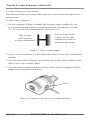
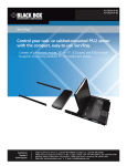
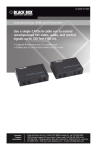
AVU4001A AVU4001A-PS Wizard Multimedia Extender LP Extend analog video up to 500 feet (152.4 m) BLACK BOX over twisted-pair cable. ® Streamlines HD digital signage setup. Customer Support Information Order toll-free in the U.S.: Call 877-877-BBOX (outside U.S. call 724-746-5500) FREE technical support 24 hours a day, 7 days a week: Call 724-746-5500 or fax 724-746-0746 • Mailing address: Black Box Corporation, 1000 Park Drive, Lawrence, PA 15055-1018 • Web site: www.blackbox.com • E-mail: [email protected] FCC and IC RFI Statements/EMC Notice Federal Communications Commission and Industry Canada Radio Frequency Interference Statements This equipment generates, uses, and can radiate radio-frequency energy, and if not installed and used properly, that is, in strict accordance with the manufacturer’s instructions, may cause interference to radio communication. It has been tested and found to comply with the limits for a Class A computing device in accordance with the specifications in Subpart B of Part 15 of FCC rules, which are designed to provide reasonable protection against such interference when the equipment is operated in a commercial environment. Operation of this equipment in a residential area is likely to cause interference, in which case the user at his own expense will be required to take whatever measures may be necessary to correct the interference. Changes or modifications not expressly approved by the party responsible for compliance could void the user’s authority to operate the equipment. This digital apparatus does not exceed the Class A limits for radio noise emission from digital apparatus set out in the Radio Interference Regulation of Industry Canada. Le présent appareil numérique n’émet pas de bruits radioélectriques dépassant les limites applicables aux appareils numériques de la classe A prescrites dans le Règlement sur le brouillage radioélectrique publié par Industrie Canada. European EMC Directive 89/336/EEC This equipment has been tested and found to comply with the limits for a Class A computing device in accordance with the specifications in the European standard EN55022. These limits are designed to provide reasonable protection against harmful interference. This equipment generates, uses and can radiate radio frequency energy and if not installed and used in accordance with the instructions may cause harmful interference to radio or television reception. However, there is no guarantee that harmful interference will not occur in a particular installation. If this equipment does cause interference to radio or television reception, which can be determined by turning the equipment on and off, the user is encouraged to correct the interference with one or more of the following measures: (a) Reorient or relocate the receiving antenna. (b) Increase the separation between the equipment and the receiver. (c) Connect the equipment to an outlet on a circuit different from that to which the receiver is connected. (d) Consult the supplier or an experienced radio/TV technician for help. Page 2 724-746-5500 | blackbox.com AVU4001A NOM Statement Instrucciones de Seguridad 1. Todas las instrucciones de seguridad y operación deberán ser leídas antes de que el aparato eléctrico sea operado. 2.Las instrucciones de seguridad y operación deberán ser guardadas para referencia futura. 3.Todas las advertencias en el aparato eléctrico y en sus instrucciones de operación deben ser respetadas. 4. Todas las instrucciones de operación y uso deben ser seguidas. 5. El aparato eléctrico no deberá ser usado cerca del agua—por ejemplo, cerca de la tina de baño, lavabo, sótano mojado o cerca de una alberca, etc.. 6. El aparato eléctrico debe ser usado únicamente con carritos o pedestales que sean recomendados por el fabricante. 7. El aparato eléctrico debe ser montado a la pared o al techo sólo como sea recomendado por el fabricante. 8. Servicio—El usuario no debe intentar dar servicio al equipo eléctrico más allá lo descrito en las instrucciones de operación. Todo otro servicio deberá ser referido a personal de servicio calificado. 9. El aparato eléctrico debe ser situado de tal manera que su posición no interfiera su uso. La colocación del aparato eléctrico sobre una cama, sofá, alfombra o superficie similar puede bloquea la ventilación, no se debe colocar en libreros o gabinetes que impidan el flujo de aire por los orificios de ventilación. 10. El equipo eléctrico deber ser situado fuera del alcance de fuentes de calor como radiadores, registros de calor, estufas u otros aparatos (incluyendo amplificadores) que producen calor. 11. El aparato eléctrico deberá ser connectado a una fuente de poder sólo del tipo descrito en el instructivo de operación, o como se indique en el aparato. 12. Precaución debe ser tomada de tal manera que la tierra fisica y la polarización del equipo no sea eliminada. AVU4001A 724-746-5500 | blackbox.com Page 3 NOM Statement 13. Los cables de la fuente de poder deben ser guiados de tal manera que no sean pisados ni pellizcados por objetos colocados sobre o contra ellos, poniendo particular atención a los contactos y receptáculos donde salen del aparato. 14. El equipo eléctrico debe ser limpiado únicamente de acuerdo a las recomendaciones del fabricante. 15. En caso de existir, una antena externa deberá ser localizada lejos de las lineas de energia. 16. El cable de corriente deberá ser desconectado del cuando el equipo no sea usado por un largo periodo de tiempo. 17. Cuidado debe ser tomado de tal manera que objectos liquidos no sean derramados sobre la cubierta u orificios de ventilación. 18. Servicio por personal calificado deberá ser provisto cuando: A: El cable de poder o el contacto ha sido dañado; u B: Objectos han caído o líquido ha sido derramado dentro del aparato; o C: El aparato ha sido expuesto a la lluvia; o D: E l aparato parece no operar normalmente o muestra un cambio en su desempeño; o E: El aparato ha sido tirado o su cubierta ha sido dañada. Page 4 724-746-5500 | blackbox.com AVU4001A Trademarks Used in this Manual/Table of Contents Trademarks Used in this Manual Black Box and the Double Diamond logo are registered trademarks, and ServSwitch is a trademark, of BB Technologies, Inc. Any other trademarks mentioned in this manual are acknowledged to be the property of the trademark owners. Table of Contents 1. Specifications................................................................................................ 6 2. Overview...................................................................................................... 7 2.1 Introduction.......................................................................................... 7 2.2 Features................................................................................................. 7 2.3 What’s Included.................................................................................... 7 2.4 You May Also Need.............................................................................. 7 2.5 Hardware Description............................................................................ 8 2.5.1 Local Unit.................................................................................... 8 2.5.2 Remote Unit................................................................................ 9 3. Connecting Your Wizard Multimedia Extender LP......................................... 10 4. Video Sharpness Adjustment........................................................................ 11 5. DDC Information.......................................................................................... 12 6. Power Control.............................................................................................. 13 AVU4001A 724-746-5500 | blackbox.com Page 5 Chapter 1: Specifications 1. Specifications Cable Requirements: Foil twisted-pair (FTP) cable, CAT5 or higher; for cable runs greater than 164 ft. (50 m); low-skew cable may also be required to prevent video color distortion Distance (Maximum): 500 ft. (152.4 m) Resolution (Maximum): HD: 1080p; VGA: 1920 x 1200 CE Approval: Yes RoHS: Yes Connectors: Transmitter: Video: (1) HD15 F; Power: (1) USB Type A M; Interconnect: (1) RJ-45; Receiver: VGA (1) HD15 F; Interconnect: (1) RJ-45 Power: From the USB connection on the transmitter Size: Both transmitter and receiver: 0.9"H x 1.8"W x 2.5"D (2.3 x 4.6 x 6.4 cm) Page 6 724-746-5500 | blackbox.com AVU4001A Chapter 2: Overview 2. Overview 2.1 Introduction Simplify HD signage setup with this USB-line-powered, CATx-based VGA extender. The Black Box Wizard Multimedia Extender LP enables you to extend analog video over a maximum of 500 feet (152.4 m) of twisted-pair cable. It’s powered via USB from the transmitter end, so no additional power supply is required at the receiver. 2.2 Features • USB line powered. Great for video in areas short on outlets. • Power from the host PC or a digital signage player with a USB port. • Transmits full HD 1080p video as far as 500 feet (152.4 m). 2.3 What’s Included Your package should include the following items. If anything is missing or damaged, contact Black Box at 724-746-5500 or [email protected]. • (1) Local unit • (1) Remote unit • This user’s manual 2.4 You May Also Need A power kit is required if the host computer or other device with a USB port cannot provide sufficient power. A Power Kit (part number AVU4001A-PS) that contains an external power adapter and USB adapter cable is also available. AVU4001A 724-746-5500 | blackbox.com Page 7 Chapter 2: Overview 2.5 Hardware Description 2.5.1 Local Unit Figure 2-1 shows the local unit. Table 2-1 describes its components. HD15 connector USB Type A connector RJ-45 connector Figure 2-1. Local unit. Table 2-1. Local unit components. Component Description HD15 connector Links to video output port USB Type A connector Provides power to the unit RJ-45 connector Interconnects via RJ-45 cable to remote unit Page 8 724-746-5500 | blackbox.com AVU4001A Chapter 2: Overview 2.5.2 Remote Unit Figure 2-2 shows the remote unit. Table 2-2 describes its components. HD15 connector RJ-45 connector Figure 2-2. Remote unit. Table 2-2. Remote unit components. Component Description HD15 connector Links to video input port RJ-45 connector Interconnects via RJ-45 cable to local unit AVU4001A 724-746-5500 | blackbox.com Page 9 Chapter 3: Connecting Your Wizard Multimedia Extender LP 3. Connecting Your Wizard Multimedia Extender LP Local unit: 1. Connect the HD15 VGA video plug to the video card in the host computer. 2. Connect the USB Type A connector to a vacant USB port on the computer. NOTE: The USB connection only provides power for the units. 3. Connect the RJ-45 plug to the video interconnect cable. Remote unit: 1. Connect the HD15 VGA video plug to the socket on the display screen. 2. Attach the other end of the RJ-45 interconnect cable to RJ-45 socket on the unit. IMPORTANT NOTES: 1. Screened (FTP) cable is preferred to connect the two units. For cable runs greater than 50 m, low-skew cable may also be required to avoid color fringing efffects within the video image. 2. Do not connect the local unit via CATx cable to anything other than the remote unit. Page 10 724-746-5500 | blackbox.com AVU4001A Chapter 3: Connecting Your Wizard Multimedia Extender LP Video and USB connections to the host computer Video connection to the display screen Figure 3-1. Connecting the local and remote extenders together via RJ-45 cable. AVU4001A 724-746-5500 | blackbox.com Page 11 Chapter 4: Video Sharpness Adjustment 4. Video Sharpness Adjustment The remote module has a video adjustment to control picture sharpness on the display screen. To adjust video sharpness: 1. On the computer, display a suitable high contrast image, ideally with one or more black vertical lines on a white background (for example, a capital “H” at 72 points in a word processor—see Figure 4-1). High contrast black character on white background Black or bright white shadow on the right indicates the need for sharpness adjustment Figure 4-1. High-contrast image. 2. Insert a small screwdriver into the adjustment screw on the side of the remote module. 3. Turn the screw fully clockwise—you should see a bright white shadow to the right of your high contrast image 4. Turn the screw counter-clockwise until the white shadow disappears and the edges of your image become sharp. Screw Figure 4-2. Screw on the side of the remote module. Page 12 724-746-5500 | blackbox.com AVU4001A Chapter 5: DDC Information 5. DDC information DDC information is not sent from the remote unit. Instead, the local unit holds a standard set of DDC details which are suitable for most display screens. If the standard details are not suitable, temporarily connect the local unit directly to the display screen that is to be emulated and power on the screen. NOTE: The local unit must be powered via its USB connection. If the DDC information is different than that already held, the yellow indicator will flicker rapidly for 2 to 3 seconds while the new information is stored. If a problem occurs while attempting to harvest DDC information, the yellow indicator on the local unit will show a number of distinct flashes. Note the number of flashes in case you need to contact technical support, but otherwise retry the procedure. AVU4001A 724-746-5500 | blackbox.com Page 13 Chapter 6: Power Control 6. Power Control IMPORTANT: Do not connect the local unit, via the CATx cable, to anything other than the remote unit. Low voltage power for the remote unit is fed via one of the pairs within the cable. The local unit always performs a check before applying power, which is shown by flashing the yellow indicator. When power is applied, the yellow indicator will remain on. The local unit will disable the power and begin flashing its yellow indicator if: • The cable is disconnected • Line power is overloaded If the host computer goes into standby (turns off the display screen by disabling sync pulses, as is usually the case) the local unit will disable line power and go into a low power mode after a period of approximately 16 seconds. It will not attempt to check the line or turn power back on. The yellow indicator will remain off until video input is restored. Page 14 724-746-5500 | blackbox.com AVU4001A NOTES AVU4001A 724-746-5500 | blackbox.com Page 15 Black Box Tech Support: FREE! Live. 24/7. Tech support the way it should be. Great tech support is just 30 seconds away at 724-746-5500 or blackbox.com. About Black Box Black Box Network Services is your source for more than 118,000 networking and infrastructure products. You’ll find everything from cabinets and racks and power and surge protection products to media converters and Ethernet switches all supported by free, live 24/7 Tech Support available in 30 seconds or less. © Copyright 2010. Black Box Corporation. All rights reserved. AVU4001A, rev. 1 724-746-5500 | blackbox.com