1
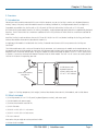
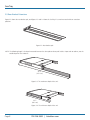
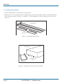
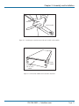
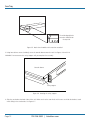
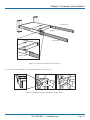
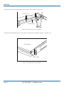
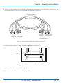
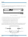
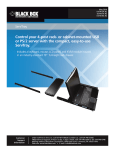
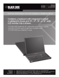
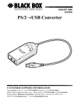
KVT201A-JP-R3
KVT202A-JP-R3
ServTray™
Control your rack- or cabinet-mounted PS/2 server
with the compact, easy-to-use BLACK
ServTray.BOX
®
Consists of a keyboard, mouse, 15" or 17" LCD panel, and KVM module
housed in an industry-standard 19", 1U-height rack drawer.
Customer
Support
Information
Order toll-free in the U.S.: Call 877-877-BBOX (outside U.S. call 724-746-5500)
FREE technical support 24 hours a day, 7 days a week: Call 724-746-5500 or fax 724-746-0746
Mailing address: Black Box Corporation, 1000 Park Drive, Lawrence, PA 15055-1018
Web site: www.blackbox.com • E-mail: [email protected]
ServTray
Federal Communications Commission and Industry Canada Radio Frequency Interference
Statements
Class B Digital Device. This equipment has been tested and found to comply with the limits for a Class B computing device pursuant to Part 15 of the FCC Rules. These limits are designed to provide reasonable protection against harmful interference in a residential installation. However, there is no guarantee that interference will not occur in a particular installation. This equipment generates, uses, and can radiate radio frequency energy, and, if not installed and used in accordance with the instructions, may cause
harmful interference to radio communications. If this equipment does cause harmful interference to radio or telephone reception,
which can be determined by turning the equipment off and on, the user is encouraged to try to correct the interference by one of
the following measures:
• Reorient or relocate the receiving antenna.
• Increase the separation between the equipment and receiver.
• Connect the equipment into an outlet on a circuit different from that to which the receiver is connected.
• Consult an experienced radio/TV technician for help.
CAUTION: Changes or modifications not expressly approved by the party responsible for compliance could void the user’s
authority to operate the equipment.
To meet FCC requirements, shielded cables and power cords are required to connect this device to a personal computer or other
Class B certified device.
This digital apparatus does not exceed the Class B limits for radio noise emission from digital apparatus set out in the Radio
Interference Regulation of Industry Canada.
Le présent appareil numérique n’émet pas de bruits radioélectriques dépassant les limites applicables aux appareils numériques de
classe B prescrites dans le Règlement sur le brouillage radioélectrique publié par Industrie Canada.
Page 2
724-746-5500 | blackbox.com
NOM Statement
Instrucciones de Seguridad
(Normas Oficiales Mexicanas Electrical Safety Statement)
1. Todas las instrucciones de seguridad y operación deberán ser leídas antes de que el aparato eléctrico sea operado.
2. Las instrucciones de seguridad y operación deberán ser guardadas para referencia futura.
3. Todas las advertencias en el aparato eléctrico y en sus instrucciones de operación deben ser respetadas.
4. Todas las instrucciones de operación y uso deben ser seguidas.
5. El aparato eléctrico no deberá ser usado cerca del agua—por ejemplo, cerca de la tina de baño, lavabo, sótano mojado o cerca
de una alberca, etc.
6. El aparato eléctrico debe ser usado únicamente con carritos o pedestales que sean recomendados por el fabricante.
7. El aparato eléctrico debe ser montado a la pared o al techo sólo como sea recomendado por el fabricante.
8. Servicio—El usuario no debe intentar dar servicio al equipo eléctrico más allá a lo descrito en las instrucciones de operación.
Todo otro servicio deberá ser referido a personal de servicio calificado.
9. El aparato eléctrico debe ser situado de tal manera que su posición no interfiera su uso. La colocación del aparato eléctrico
sobre una cama, sofá, alfombra o superficie similar puede bloquea la ventilación, no se debe colocar en libreros o gabinetes
que impidan el flujo de aire por los orificios de ventilación.
10. El equipo eléctrico deber ser situado fuera del alcance de fuentes de calor como radiadores, registros de calor, estufas u otros
aparatos (incluyendo amplificadores) que producen calor.
11. El aparato eléctrico deberá ser connectado a una fuente de poder sólo del tipo descrito en el instructivo de operación, o como
se indique en el aparato.
12. Precaución debe ser tomada de tal manera que la tierra fisica y la polarización del equipo no sea eliminada.
13. Los cables de la fuente de poder deben ser guiados de tal manera que no sean pisados ni pellizcados por objetos colocados
sobre o contra ellos, poniendo particular atención a los contactos y receptáculos donde salen del aparato.
14. El equipo eléctrico debe ser limpiado únicamente de acuerdo a las recomendaciones del fabricante.
15. En caso de existir, una antena externa deberá ser localizada lejos de las lineas de energia.
16. El cable de corriente deberá ser desconectado del cuando el equipo no sea usado por un largo periodo de tiempo.
17. Cuidado debe ser tomado de tal manera que objectos liquidos no sean derramados sobre la cubierta u orificios de ventilación.
18. Servicio por personal calificado deberá ser provisto cuando:
A: El cable de poder o el contacto ha sido dañado; u
B: Objectos han caído o líquido ha sido derramado dentro del aparato; o
C: El aparato ha sido expuesto a la lluvia; o
D: El aparato parece no operar normalmente o muestra un cambio en su desempeño; o
E: El aparato ha sido tirado o su cubierta ha sido dañada.
724-746-5500 | blackbox.com
Page 3
ServTray
Trademarks Used in this Manual
Black Box and the Double Diamond logo are registered trademarks, and ServTray and ServSwitch are trademarks,
of BB Technologies, Inc.
Centronics is a registered trademark of Centronics Corporation.
UL is a registered trademark of Underwriters Laboratories Inc.
Any other trademarks mentioned in this manual are acknowledged to be the property of the trademark owners.
We‘re here to help! If you have any questions about your application
or our products, contact Black Box Tech Support at 724-746-5500
or go to blackbox.com and click on “Talk to Black Box.”
You’ll be live with one of our technical experts in less than 20 seconds.
Page 4
724-746-5500 | blackbox.com
Table of Contents
Table of Contents
Chapter
Page
1. Specifications...............................................................................................................................................................................................6
2. Overview......................................................................................................................................................................................................7
2.1 Introduction.........................................................................................................................................................................................7
2.2 What’s Included...................................................................................................................................................................................7
2.3 Rear Bracket Extensions.......................................................................................................................................................................8
3. Assembly and Installation...........................................................................................................................................................................10
4. Operation...................................................................................................................................................................................................16
5. Troubleshooting......................................................................................................................................................................................... 17
5.1 Calling Black Box............................................................................................................................................................................... 17
5.2 Shipping and Packaging.................................................................................................................................................................... 17
724-746-5500 | blackbox.com
Page 5
ServTray
1. Specifications
Approvals: CE, FCC for the product; UL®, TUV, CE for power supply
Active Display Area: KVT201A-JP-R3: 9"H x 12"W (22.8 x 30.4 cm);
KVT202A-JP-R3: 10.6"H x 13.3"W (27 x 33.8 cm)
Pixel Pitch: KVT201A-JP-R3: 0.297 mm (H) x 0.297 mm (V);
KVT202A-JP-R3: 0.264 mm (H) x 0.264 mm (V)
Resolution: KVT201A-JP-R3: 1024 x 768 @ 60 Hz;
KVT202A-JP-R3: 1280 x 1024 @ 60 Hz
NOTE: For optimum video performance, VGA resolution should be set to 1024 x 768 (for the KVT201A-JP-R3) or 1280 x 1024 (for
the KVT202A-JP-R3).
Display Mode: Normally white
Brightness (cd/m^2): 250 (center)
Contrast Ratio (typical): KVT201A-JP-R3: 350:1;
KVT202A-JP-R3: 450:1
Display Color (RGB 6-bit data): 262 K colors
Input Signal: RGB analog, H/V separate
Plug-n-Play VESA: VESA DDC 1/2B
Viewing Angle (typical): KVT201A-JP-R3: -70 to +70 (H), -60 to +60 (V);
KVT202A-JP-R3: -80 to +80 (H), -80 to +80 (V)
Backlight Unit: KVT201A-JP-R3: 2 CCFLs edge-light (top/bottom);
KVT202A-JP-R3: 4 CCFLs edge-light (top/bottom)
Connectors: (1) Centronics® female, (2) 6-pin mini DIN, (1) HD15, (1) barrel connector for power
Temperature: Operating: 32 to 122° F (0 to 50° C);
Storage: -4 to +140° F (-20 to +60° C)
Humidity (Relative): 95%
Power Consumption (maximum, typical): KVT201A-JP-R3: 33 watts;
KVT202A-JP-R3: 37 watts
Power: 12 VDC (from external 100–240-VAC power adapter), 47–63 Hz
Size: KVT201A-JP-R3: 1.75"H (1U) x 15"W x 19.5" to 39.5"D (4.4 x 38.1 x 49.5 to 100.3 cm);
KVT202A-JP-R3: 1.75"H (1U) x 17"W x 19.5" to 39.5"D (4.4 x 43.2 x 49.5 to 100.3 cm)
Weight: KVT201A-JP-R3: 21 lb. (9.5 kg);
KVT202A-JP-R3: 23 lb. (10.4 kg)
Page 6
724-746-5500 | blackbox.com
Chapter 2: Overview
2. Overview
2.1 Introduction
Control your rack- or cabinet-mounted PS/2 server with the compact, easy-to-use ServTray. It consists of a keyboard (Japanese
version), mouse, LCD panel, and KVM module housed in an industry-standard 19", 1U-height console drawer (see Figure 2-1).
Two models are available: the ServTray with a 15" LCD panel (KVT201A-JP-R3) and the ServTray with a 17" LCD panel
(KVT202A-JP-R3). Both models feature a full 105-key, low-profile, sturdy keyboard and touch pad with an ergonomically designed
hand rest. The KVT201A-JP-R3 has a maximum resolution of 1024 x 768, and the KVT202A-JP-R3 has a maximum resolution of
1280 x 1024.
Install the ServTray in racks or cabinets that are 23.7"D to 45.3"D (60.2 to 115.1 cm). Before installing the ServTray, you’ll need a
Universal Rear Bracket Extension Kit (described in Section 2.3).
A single-port KVM module is included with the ServTray. To control more than one PS/2 server, connect the ServTray to a
ServSwitch™.
The KVM module comes with a universal Centronics 36-pin connector; use it to connect the module to the console drawer. On
the opposite side of the KVM module are two 6-pin mini DIN connectors and one HD15 connector to connect directly to a PS/2
computer or to a ServSwitch console ports. Finally, the module has a barrel connector for power. The 0.12" x 0.24" screws listed
in Section 2.2 secure the Universal Rear Bracket Extension Kit to the KVM module. The 0.19" x 0.43" screws are used in place of
10-32 or 12-24 screws if required by your rack.
Universal rear bracket
extension kit
KVM
module
1U slide drawer with
keyboard (Japanese
version), touch pad, and
15" or 17" LCD monitor
Figure 2-1. ServTray components (left to right): Universal Rear Bracket Extension Kit, KVM Module, and 1U slide drawer.
2.2 What’s Included
• (1) ServTray console (15" or 17" LCD panel, keyboard [Japanese version], and mouse pad)
• (1) KVM module with power supply
• (1) Universal rear bracket extension kit
• (1) PS/2 CPU cable
• (10) 0.19" x 0.43" (0.5 x 1.1 cm) screws
• (10) 0.12" x 0.24" (0.3 x 0.6 cm) screws
• This user’s manual
Accessories that you might or need to purchase include:
• 12-24 or 10-32 nuts/bolts
724-746-5500 | blackbox.com
Page 7
ServTray
2.3 Rear Bracket Extensions
Figure 2-2 shows the rear bracket pair, and Figures 2-3 and 2-4 show the ServTray in its maximum and minimum extension
positions.
Figure 2-2. Rear bracket pair.
NOTE: The following length is the depth measured between the front pole and rear pole inside a 4-post rack or cabinet, not the
outside depth of the enclosure.
45.3"
(115.1 cm)
Figure 2-3. The maximum depth of the unit.
23.7"
(60.2 cm)
Figure 2-4. The minimum depth of the unit.
Page 8
724-746-5500 | blackbox.com
Chapter 2: Overview
Open rack
Open rack
ServTray
Figure 2-5. ServTray installed on an open rack.
724-746-5500 | blackbox.com
Page 9
ServTray
3. Assembly and Installation
1. Choose a proper position in the cabinet for the console drawer.
2. Using four 0.12" x 0.24" countersunk screws (included), attach the extensions (included with your ServTray Kit) to both sides
of the KVM switch module. See Figures 3-1 through 3-5. The wide-edged plastic extension should be on the top side (see
Figure 3-5).
Rear brackets
Extensions
Figure 3-1. Rear brackets and extensions.
KVM module
(4) counter-sunk
screws
Extension
Figure 3-2. Attaching the extensions to the KVM module.
Page 10
724-746-5500 | blackbox.com
Chapter 3: Assembly and Installation
Extension
Switch module
Figure 3-3. Attaching an extension to one side of the KVM switch module.
Extension on
side of switch
module
Switch
module
Figure 3-4. KVM switch module with extensions attached.
724-746-5500 | blackbox.com
Page 11
ServTray
The wide-edged plastic
extension should be on
the top side.
Figure 3-5. Back view of module with extensions attached.
3. Using four cabinet screws (included), screw the console drawer onto the rack. See Figures 3-6 and 3-10.
WARNING: Do not remove the safety stopper until you complete the assembly.
Console drawer
Safety stopper
Figure 3-6. Locating the safety stopper.
4. Slide the rear bracket into both sides of the unit. Make sure that the two wheels with screws are inside the bracket’s track
while sliding in the rear bracket. See Figure 3-7.
Page 12
724-746-5500 | blackbox.com
Chapter 3: Assembly and Installation
Rear bracket
ServTray
Rear bracket
Bracket track
Figure 3-7. Install the rear bracket onto the ServTray.
5. Push the KVM switch module evenly towards the drawer. See Figure 3-8.
Figure 3-8. Pushing the module towards the console drawer.
724-746-5500 | blackbox.com
Page 13
ServTray
6. Slide the console drawer out and tightly fasten the screw to the module. See Figure 3-9.
Thumbscrews
KVM module
Console drawer
Figure 3-9. Fasten the screw to the module.
7. Remove the safety stoppers from the front sides of the drawer (left and right) in sequence. See Figure 3-10.
Console drawer
Safety stopper
Figure 3-10. Removing the safety stoppers.
Page 14
724-746-5500 | blackbox.com
Chapter 3: Assembly and Installation
8. Once the ServTray is installed in the rack or cabinet, you can connect it to a computer. The KVM module’s connectors attach to
the KVM connectors on a PS/2 CPU via the CPU cable (included) shown in Figure 3-11.
CPU cable (included)
This side attaches to the
ServTray unit’s KVM module
HD15 male
connector
(2) 6-pin mini DIN
male connectors
This side connects
to the computer/server
Figure 3-11. Cable for connecting the KVM module to a computer.
9. Connect the power supply to the power jack on the switch module. See Figure 3-12.
Power
connector
Figure 3-12. Attaching the power supply to the module.
To replace a module, follow Steps 5 and 6 on pages 13–14.
724-746-5500 | blackbox.com
Page 15
ServTray
4. Operation
Once the ServTray is installed and connected to a PS/2 CPU or ServSwitch, it’s ready for operation. Control the unit via the buttons on the LCD panel (labeled 1 and 2 in Figure 4-1) and the LCD panel power switch (labeled 3 in Figure 4-1). Monitor the status via the keyboard status keys (labeled 4, 5, and 6 in Figure 4-1).
3
1
2
1
2
4
5
6
Figure 4-1. The ServTray components.
1. Use the LCD panel menu buttons (1 in Figure 1) to invoke the OSD menu to set the LCD panel as an ordinary LCD monitor.
2. Use the LCD panel adjustment buttons (2 in Figure 4-1) to adjust settings for the LCD panel.
3. Switch the power to the LCD panel on or off via the power switch (3 in Figure 4-1).
4. Use the keyboard status keys (Num Lock, Caps Lock, and Scroll Lock) to view status.
• The Num Lock key (labeled 4) shows the Keyboard Num Lock status (on or off).
• The Caps Lock key (labeled 5) shows the Keyboard Caps Lock status (on or off).
• The Scroll Lock key (labeled 6) shows the Keyboard Scroll Lock status (on or off).
5. Use the touch pad (see Figure 4-2) to simulate a wheel mouse. The touch pad’s area to the right side of the two small triangular marks is the simulated scroll area. Move your finger along this area to scroll up or down on the computer’s screen. The
touch pad area enables you to move the cursor anywhere on your computer’s screen by sliding your finger along this area.
Area for
scroll wheel
Area for
touch pad
Right button
Left button
Figure 4-2. Touch pad.
Page 16
724-746-5500 | blackbox.com
Chapter 5: Troubleshooting
5. Troubleshooting
5.1 Calling Black Box
If you determine that your ServTray is malfunctioning, do not attempt to alter or repair the unit. It contains no user-serviceable
parts. Contact Black Box at 724-746-5500.
Before you do, make a record of the history of the problem. We will be able to provide more efficient and accurate assistance if
you have a complete description, including:
• the nature and duration of the problem.
• when the problem occurs.
• the components involved in the problem.
• any particular application that, when used, appears to create the problem or make it worse.
5.2 Shipping and Packaging
If you need to transport or ship your ServTray:
• Package it carefully. We recommend that you use the original container.
• If you are shipping the ServTray for repair, make sure you include everything that came in the original package. Before you ship,
contact Black Box to get a Return Authorization (RA) number.
724-746-5500 | blackbox.com
Page 17
Black Box Tech Support: FREE! Live. 24/7.
Tech support the
way it should be.
Great tech support is just 20 seconds away at 724-746-5500 or blackbox.com.
About Black Box
Black Box Network Services is your source for more than 118,000 networking and infrastructure products. You’ll find everything
from cabinets and racks and power and surge protection products to media converters and Ethernet switches all supported by
free, live 24/7 Tech support available in 20 seconds or less.
© Copyright 2010. All rights reserved.
KVT201A-JP-R3, rev. 1
724-746-5500 | blackbox.com