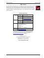
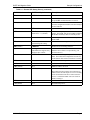
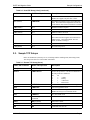
1
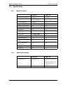
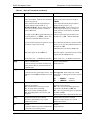
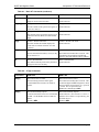
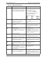
Sierra Wireless
DART 300 CDPD Modem
Migration Guide
For Users of the DART 200
2110291 Rev 1.0
November 2000
DART 300 Modem
Migration Guide
Important Notice
Because of the nature of wireless communications, transmission and reception of data can never be guaranteed.
Data may be delayed, corrupted (i.e., have errors) or be totally lost. Although significant delays or losses of data are
rare when wireless devices such as the Sierra Wireless modem are used in a normal manner with a well-constructed
network, the Sierra Wireless modem should not be used in situations where failure to transmit or receive data could
result in damage of any kind to the user or any other party, including but not limited to personal injury, death, or loss
of property. Sierra Wireless, Inc., accepts no responsibility for damages of any kind resulting from delays or errors
in data transmitted or received using the Sierra Wireless modem, or for failure of the Sierra Wireless modem to
transmit or receive such data.
Safety and Hazards
Do not operate the Sierra Wireless modem in areas where blasting is in progress, where explosive atmospheres may
be present, near medical equipment, near life support equipment, or any equipment which may be susceptible to any
form of radio interference. In such areas, the Sierra Wireless modem MUST BE TURNED OFF. The Sierra
Wireless modem can transmit signals that could interfere with this equipment.
Do not operate the Sierra Wireless modem in any aircraft, whether the aircraft is on the ground or in flight. In
aircraft, the Sierra Wireless modem MUST BE TURNED OFF. When operating, the Sierra Wireless modem can
transmit signals that could interfere with various onboard systems.
The driver or operator of any vehicle should not operate the Sierra Wireless modem while in control of a vehicle.
Doing so will detract from the driver or operator’s control and operation of that vehicle. In some states and
provinces, operating such communications devices while in control of a vehicle is an offense.
Patents
Portions of this product are covered by some or all of the following US patents: D367062, D372248, D372701,
5515013, 5617106, 5629960, 5682602, 5748449, and other patents pending.
Copyright
©2000 Sierra Wireless, Inc. All rights reserved.
Printed in Canada.
No part of this publication may be reproduced, stored in a retrieval system, or transmitted in any form or by any
means, without the prior permission of the publisher.
The information in this manual is subject to change without notice and does not represent a commitment on the part
of Sierra Wireless, Inc. Sierra Wireless, Inc. shall not be liable for incidental or consequential damages resulting
from the furnishing, performance, or use of this manual.
Trademarks
Windows® and Microsoft® are registered trademarks of Microsoft Corporation.
Hayes™ is a trademark of Hayes Microcomputer Products, Inc.
All other brand or product names, logos, trademarks, etc. mentioned in this manual are owned by their respective
companies.
2110291 Rev 1.0
Page i
DART 300 Modem
Migration Guide
Regulatory Information
The equipment certifications appropriate to your device are marked on the device and the accompanying product
specific information. Where appropriate, the use of the equipment is subject to the following conditions:
CAUTION
Unauthorized modifications or changes not expressly approved by Sierra Wireless, Inc.
could void compliance with regulatory rules, and thereby your authority to use this
equipment.
WARNING (EMI) - United States FCC Information
This equipment has been tested and found to comply with the Class B limits pursuant to
Part 15 of the FCC Rules. These limits are designed to provide reasonable protection
against harmful interference in an appropriate installation. This equipment generates,
uses, and can radiate radio frequency energy and, if not installed and used in
accordance with the instructions, may cause harmful interference to radio
communication. However, there is no guarantee that interference will not occur in a
particular installation. If this equipment does cause harmful interference to radio or
television reception, which can be determined by turning the equipment off and on, the
user is encouraged to try to correct the interference by one or more of the following
measures:
•
•
•
•
Reorient or relocate the receiving antenna
Increase the separation between the equipment and receiver
Connect the equipment into an outlet on a circuit different from that to which the
receiver is connected
Consult the dealer or an experienced radio/TV technician for help
WARNING – FCC RF Exposure Guidelines
While this device is in operation, a separation distance of at least 20cm must be
maintained between the radiating antenna and the body of all persons exposed by the
transmitter to meet FCC exposure guidelines.
This transmitter is only approved to operate with an antenna not exceeding 1.5 watts
total system ERP (effective radiated power) for operations with the antenna located at
more than 20 cm from all persons. The warning label must be displayed at the base of
the antenna (if stand-alone) or attached to the final product (if the antenna is integral
with the product), clearly visible to all persons exposed to the transmitter.
WARNING (EMI) – Canada
This digital apparatus does not exceed the Class B limits for radio noise emissions
from digital apparatus as set out in the interference causing equipment standard
entitled 'Digital Apparatus', ICES-003 of the Department of Communications.
Cet appareil numérique respecte les limites de bruits radioélectriques applicables aux
appareils numériques de Classe B prescrites dans la norme sur le matériel brouilleur:
'Appareils Numériques', NMB-003 édictée par le ministre des Communications.
2110291 Rev 1.0
Page ii
DART 300 Modem
Migration Guide
RSA Licensee
If you have purchased this product under a United States Government contract, it shall be subject to
restrictions as set forth in subparagraph (c)(1)(ii) of Defense Federal Acquisitions Regulations
(DFARs) Section 252.227-7013 for Department of Defense contracts, and as set forth in Federal
Acquisitions Regulations (FARs) Section 52.227-19 for civilian agency contracts or any successor
regulations. If further government regulations apply, it is your responsibility to ensure compliance
with such regulations.
Contact Information
Technical
Support:
Sales Desk:
Canada/US:
1-877-231-1144
Worldwide:
1-604-231-1128
Hours:
6:00am to 5:00pm Pacific Time
e-mail:
[email protected]
Phone:
1-604-232-1488
Hours:
8:00am to 5:00pm Pacific Time
e-mail:
[email protected]
Post:
Sierra Wireless, Inc.
13575 Commerce Parkway
Suite 150
Richmond, BC
Canada
V6V 2L1
Fax:
1-604-231-1109
Web:
www.sierrawireless.com
Your comments and suggestions on improving this documentation
are welcome and appreciated. Please email your feedback to
[email protected]. Thank you.
Consult our website for
up-to-date product descriptions, documentation,
application notes, firmware upgrades,
troubleshooting tips, and press releases:
www.sierrawireless.com
2110291 Rev 1.0
Page iii
DART 300 Modem
Migration Guide
Contents
1.
About this Guide .............................................................................1
1.1. Introduction .............................................................................................................1
1.1.1.
Document Structure ................................................................................1
1.2. References ................................................................................................................1
1.3. Currency ..................................................................................................................2
1.4. Conventions Used in this Reference ......................................................................2
2.
Sample Configurations...................................................................3
2.1. Sample UDP Setups ................................................................................................3
2.2. Sample TCP Setups.................................................................................................6
3.
Difference Summary .....................................................................10
3.1. Interfaces................................................................................................................10
3.1.1.
Serial Interface Specifications...............................................................10
3.1.2.
Control Lines.........................................................................................11
3.1.3.
Packet Service Interfaces ......................................................................12
3.1.4.
Modem Control Interface......................................................................12
3.2. Operation ...............................................................................................................13
3.2.1.
Monitoring Network Connection ..........................................................13
3.2.2.
Channel Acquisition Restrictions..........................................................13
3.2.3.
TCP Characteristics...............................................................................14
3.2.4.
UDP Characteristics ..............................................................................15
3.3. Additional Control Considerations .....................................................................16
3.3.1.
Escape Sequence ...................................................................................16
3.3.2.
Packet Assembly / Disassembly (PAD) Features .................................16
3.4. Specifications .........................................................................................................18
2110291 Rev 1.0
3.4.1.
Modem Features....................................................................................18
3.4.2.
Radio Specifications..............................................................................18
3.4.3.
Electrical Specification .........................................................................19
Page iv
DART 300 Modem
4.
Migration Guide
Comparative AT Command Reference .......................................20
4.1. Introduction ...........................................................................................................20
4.2. AT Command Set..................................................................................................20
4.3. DART 300 Specific Commands ...........................................................................29
4.4. Status Registers .....................................................................................................31
4.4.1.
S-Registers ............................................................................................31
4.4.2.
WS-Registers in the DART 300............................................................34
4.5. Result Codes ..........................................................................................................35
2110291 Rev 1.0
Page v
1.
About this Guide
1.1. Introduction
This Migration Guide is designed to assist application software developers who have experience
with the DART 200 in porting applications for use with the new DART 300 CDPD modem.
Installations will require changes to the DART configuration commands used on the DART 200 in
order to use the DART 300 in its place. There should not be a need to alter either local or remote
system applications related to end-to-end communication. Only the DART modem’s initial onetime configuration needs to be converted.
1.1.1.
Document Structure
This guide is organized into the following sections:
• Section 1, About this Guide, introduces the references and conventions used.
• Section 2, Sample Configurations, provides DART 300 equivalents of the samples
that were included in the original DART 200 User Manual.
• Section 3, Difference Summary, highlights the differences between the two models in
areas such as: interfaces, operation, and control considerations, as well as
specifications.
• Section 4, Comparative AT Command Reference, cross-references the commands
and registers of the DART 200 and the DART 300.
The final section, providing the command and register comparison, first presents the list of
DART 200 commands and registers and their equivalents in the DART 300. This list should allow
you to translate any existing DART 200 configuration into an equivalent DART 300 set-up.
There is then an additional list of commands, unique to the DART 300, with an explanation of
how the DART 200 would achieve the same function. This is provided to help users familiar with
the DART 200 to better understand the commands available in the DART 300.
1.2. References
For background information on the nature of wireless communications consult your cellular
service provider and/or their Internet site. All major service providers provide web-based
information on CDPD.
The Sierra Wireless web site at www.sierrawireless.com includes a document library in the
Support and Downloads section. This library includes other useful documents such as:
• DART 300 User’s Guide, 2110212
• Glossary of Terms and Acronyms, 2110032
• CDPD Primer, 2130006
• Problem Report Sheet, 2110125
2110291 Rev 1.0
Page 1
DART 300 Migration Guide
Introduction
1.3. Currency
This document may be revised from time to time as new firmware and features are made available.
Please check our website for revisions. This edition is:
Rev 1.0 November 8, 2000
DART 300 / SB300
This document is current with the modem firmware revision R1.3.5. To determine your firmware
revision:
1. Enter the Identification command ATI5
The modem will respond with the Firmware revision information:
R1_3_5 …
The details following the revision number include Sierra information on the specific build
followed by the date and time of the build.
1.4. Conventions Used in this Reference
Result Code – This is a numeric or text code that is returned after all AT commands (except
resets).
Response – This term indicates a response from the modem that is issued prior to a result code.
Reading registers or issuing commands that report information will provide a response followed
by a result code unless the command generates an error.
Numbers are assumed decimal. Hexadecimal values are shown with a prefix of 0x, i.e. in the form
0x3F. Binary values are shown with a prefix of 0b, i.e. in the form 0b01101011.
Character codes that are described with words or standard abbreviations are shown within angle
brackets: such as <CR> for Carriage Return and <SP> for a blank space character.
AT Command and register syntax is noted using an alternate font:
AT+WS46=4
Responses and result codes from the modem are shown in an alternate font:
NO CARRIER
WARNING
Notes in this form denote a physical hazard. The warning calls attention to a
procedure or practice, which if not performed correctly could result in personal injury.
CAUTION
Notes in this form highlight a procedure or practice which, if not performed correctly,
could result in loss of data or damage to equipment. This is also used to highlight
issues related to regulatory limitations.
NOTE
This form of note draws attention to procedures or practices which, if not performed
correctly, could result in failure of a process or improper configuration. These are
typically pre-requisites to other operations.
2110291 Rev 1.0
Page 2
2.
Sample Configurations
The DART 200 User’s Guide contained several sample configurations. This section provides the
equivalent configurations for the DART 300 modem to illustrate the scope of configuration
differences. The commands for both the DART 200 and DART 300 are shown side by side for
comparison.
Details of the differences in behaviour between the two modems are summarized in subsequent
sections. The comparative AT Command Reference at the end of this guide provides additional
details to aid in translating an existing DART 200 configuration into an equivalent DART 300 setup.
2.1. Sample UDP Setups
Below are the Remote (telemetry server) UDP Setup and the matching Host (monitoring client)
UDP Setup from Section 5 of the DART 200 manual.
Table 2-1 Remote UDP Setup (Server)
DART 200 Command
DART 300 Equivalent
Description
^A<ip>
+WPNEI=<ip>
Set the IP address (NEI) of the modem.
\N<s2>
+WS174=<s3>
\J0 (default)
+WPSPNI=<enter>
Set the side preference. The direct translation of
the side preference numbers is:
s2
s3
1
3
A Only
2
4
B Only
3
1
A Preferred
4
2
B Preferred
No channel restrictions, no SPNI matching.
\R4
+WS173=1
Use auto-registration mode.
S13=0
N/A
Continuous automatic registration. The
DART 300 always uses continuous mode.
\O0
+WS45=0
Set (UDP) PAD mode.
*A2
Handled by previous
command.
UDP Server mode.
*L2100 (default)
+WS212=2100 (default)
Listen on port 2100.
S0=1
S0=1 (default)
Auto-answer mode.
S82=0
+WS217=0 (default)
Turn off UDP server receive lock. The
DART 200 command also disables use of friends.
The DART 300 disables friends if the list is empty
(the default condition).
Consult Section 3.2.4.1 below for a discussion of
the receive lock.
E0
E0
Command state echo off.
V0
V0
Use numeric result codes.
Q0 (default)
Q0 (default)
Disable Quiet mode.
2110291 Rev 1.0
Page 3
DART 300 Migration Guide
Sample Configurations
Table 2-1 Remote UDP Setup (Server) (continued)
DART 200 Command
DART 300 Equivalent
Description
F1 (default)
+WS62=0
Data state echo off.
X1 (default)
N/A
Extended result codes. The DART 300 will
accept the X1 command but takes no action.
&C1 (default)
N/A
DCD follows state of connection. The DART 300
uses this configuration and does not allow changes
to DCD function.
&D0 (default)
&D0
Ignore DTR for data state escape.
&E2
S2=43 (Sets TDES escape
character to “+”) (default)
Enable the escape sequence and filter it from the
packet. The DART 300 ensures TDES is enabled;
the DART 300 always filters it from the packet.
&S0 (default)
N/A
DSR always active. The DART 300 always
asserts DSR.
\F3 (default)
Not needed, the next command
would change the setting.
Includes PAD forwarding character in packet.
\M0 (default)
+WS63=0
Disables PAD forwarding character.
\Q0
Not supported.
The DART 300 supports only
hardware flow control.
No flow control. (See Section 3.1.1 below if
hardware flow control is not provided by your
local host device.)
\T1 (default)
+WS70=20
Timed data forwarding (always used with binary
data). The DART 200 configuration assumes use
of the default value in S50 (20 tenths of a second).
*B0 (default)
N/A
Disable broadcast reception.
*C1 (default)
N/A
Enable SLIP TCP header compression.
*G1 (default)
N/A
Multicast address selection.
*K0 (default)
S30=0 (default)
Session timeout not used in UDP on DART 200.
The DART 300 does support session timeout on
UDP sessions and will require it if receive locking
is not used and the local device cannot close the
session. Consult the DART 300 User Guide for
details on using it.
*R0 (default)
N/A
Auto-SLIP disabled.
*T0 (default)
N/A
No Telnet keep-alives.
2110291 Rev 1.0
Page 4
DART 300 Migration Guide
Sample Configurations
Table 2-2 Host UDP Setup (client)
DART 200 Command
DART 300 Equivalent
Description
^A<ip>
+WPNEI=<ip>
Set the IP address (NEI) of the modem.
\N<s2>
+WS174=<s3>
Set the side preference. The direct translation of
the side preference numbers is:
s2
s3
1
3
A Only
2
4
B Only
3
1
A Preferred
4
2
B Preferred
\J0 (default)
+WPSPNI=<enter>
No channel restrictions, no SPNI matching.
\R4
+WS173=1
Use auto-registration mode.
S13=0
N/A
Continuous automatic registration. The
DART 300 always uses continuous mode.
\O0
+WS45=0
Set (UDP) PAD mode.
*A0 (default)
S0=0 (manual answer)
+WS212=0 (disable server)
No server required.
*L2100 (default)
+WS212=2100 (default)
Listen on port 2100.
S82=0
+WS217=0 (default)
Turn off UDP server receive lock. The
DART 200 command also disables use of friends.
The DART 300 disables friends if the list is empty
(the default condition).
E0
E0
Command state echo off.
V0
V0
Use numeric result codes.
Q0 (default)
Q0 (default)
Disable Quiet mode.
F1 (default)
+WS62=0
Data state echo off.
X1 (default)
N/A
Extended result codes. The DART 300 will
accept the X1 command but takes no action.
&C1 (default)
N/A
DCD follows state of connection. The DART 300
uses this configuration and does not allow changes
to DCD function.
&D0 (default)
&D0
Ignore DTR.
&E2
S2=43 (Sets TDES escape
character to “+”) (default)
Enable the escape sequence and filter it from the
packet. The DART 300 ensures TDES is enabled;
the DART 300 always filters it from the packet.
&S0 (default)
N/A
DSR always active. The DART 300 always
asserts DSR.
\F3 (default)
Not needed, the next command
would change the setting.
Includes PAD forwarding character in packet.
\M0 (default)
+WS63=0
Disables PAD forwarding character.
2110291 Rev 1.0
Page 5
DART 300 Migration Guide
Sample Configurations
Table 2-2 Host UDP Setup (client) (continued)
DART 200 Command
DART 300 Equivalent
Description
\Q2 (default)
N/A
Use hardware flow control (RTS/CTS). The
DART 300 supports only this flow control.
\T1 (default)
+WS70=20
Timed data forwarding (always used with binary
data). The DART 200 configuration assumes use
of the default value in S50 (20 tenths of a second).
*B0 (default)
N/A
Disable broadcast reception.
*C1 (default)
N/A
Enable SLIP TCP header compression.
*G1 (default)
N/A
Multicast address selection.
*K0 (default)
S30=0 (default)
Session timeout not used in UDP on DART 200.
The DART 300 does support session timeout on
UDP sessions. Consult the DART 300 User
Guide for details on using it.
*R0 (default)
N/A
Auto-SLIP disabled.
*T0 (default)
N/A
No Telnet keep-alives.
2.2. Sample TCP Setups
Below are the Remote (telemetry server) TCP Setup and the matching Host (monitoring client)
TCP Setup from Section 5 of the DART 200 manual.
Table 2-3 Remote TCP Setup (Server)
DART 200 Command
DART 300 Equivalent
Description
^A<ip>
+WPNEI=<ip>
Set the IP address (NEI) of the modem.
\N<s2>
+WS174=<s3>
\J0
+WPSPNI=<enter>
Set the side preference. The direct translation of
the side preference numbers is:
s2
s3
1
3
A Only
2
4
B Only
3
1
A Preferred
4
2
B Preferred
No channel restrictions, no SPNI matching.
\R4
+WS173=1
Use auto-registration mode.
S13=0
N/A
Continuous automatic registration. The
DART 300 always uses continuous mode.
\O0
+WS45=1
Set (TCP) PAD mode.
*A1
Handled by previous
command.
TCP Server mode.
S0=1
S0=1 (default)
Auto-answer mode.
*L2100 (default)
+WS212=2100 (default)
Listen on port 2100.
E0
E0
Command state echo off.
2110291 Rev 1.0
Page 6
DART 300 Migration Guide
Sample Configurations
Table 2-3 Remote TCP Setup (Server) (continued)
DART 200 Command
DART 300 Equivalent
Description
V0
V0
Use numeric result codes.
Q0 (default)
Q0 (default)
Disable Quiet mode.
F1 (default)
+WS62=0
Data state echo off.
X1 (default)
N/A
Extended result codes. The DART 300 will
accept the X1 command but takes no action.
&C1 (default)
N/A
DCD follows state of connection. The DART 300
uses this configuration and does not allow changes
to DCD function.
&D0 (default)
&D0
Ignore DTR for data state escape.
&E2
S2=43 (Sets TDES escape
character to “+”) (default)
Enable the escape sequence and filter it from the
packet. The DART 300 ensures TDES is enabled;
the DART 300 always filters it from the packet.
&S0 (default)
N/A
DSR always active. The DART 300 always
asserts DSR.
\F3 (default)
Not needed, the next command
would change the setting.
Includes PAD forwarding character in packet.
\M0 (default)
+WS63=0
Disables PAD forwarding character.
\Q0
Not supported.
The DART 300 supports only
hardware flow control.
No flow control. (See Section 3.1.1 below if
hardware flow control is not provided by your
local host device.)
\T1 (default)
+WS70=20
Timed data forwarding (always used with binary
data). The DART 200 configuration assumes use
of the default value in S50 (20 tenths of a second).
*B0 (default)
N/A
Disable broadcast reception.
*C1 (default)
N/A
Enable SLIP TCP header compression.
*G1 (default)
N/A
Multicast address selection.
*K2
Not supported.
The DART 300 supports only
an idle session timeout (S30).
Receive keep-alive; unidirectional.
S86=3
Keep-alive timer set to 3 minutes.
Not supported.
The DART 300 supports only a
With the DART 200 setting of *K2 above, the
bi-directional idle session
DART 300 setting of S30=3 is an equivalent with
timeout (S30=3).
the exception that any dummy keep-alive packets
will not be discarded by the DART 300. See
Section 3.2.3.1 below for details.
*R0 (default)
N/A
Auto-SLIP disabled.
*T0 (default)
N/A
No Telnet keep-alives.
2110291 Rev 1.0
Page 7
DART 300 Migration Guide
Sample Configurations
Following is the client side configuration for a TCP installation.
Table 2-4 Host TCP Setup (client)
DART 200 Command
DART 300 Equivalent
Description
^A<ip>
+WPNEI=<ip>
Set the IP address (NEI) of the modem.
\N<s2>
+WS174=<s3>
Set the side preference. The direct translation of
the side preference numbers is:
s2
s3
1
3
A Only
2
4
B Only
3
1
A Preferred
4
2
B Preferred
\J0 (default)
+WPSPNI=<enter>
No channel restrictions, no SPNI matching.
\R4
+WS173=1
Use auto-registration mode.
S13=0
N/A
Continuous automatic registration. The
DART 300 always uses continuous mode.
\O0
+WS45=1
Set (TCP) PAD mode.
*A0 (default)
S0=0 (manual answer)
+WS212=0 (disable server)
No server required.
*L2100 (default)
+WS212=2100 (default)
Listen on port 2100.
E0
E0
Command state echo off.
V0
V0
Use numeric result codes.
Q0 (default)
Q0 (default)
Disable Quiet mode.
F1 (default)
+WS62=0
Data state echo off.
X1 (default)
N/A
Extended result codes. The DART 300 will
accept the X1 command but takes no action.
&C1 (default)
N/A
DCD follows state of connection. The DART 300
uses this configuration and does not allow changes
to DCD function.
&D0 (default)
&D0
Ignore DTR.
&E2
S2=43 (Sets TDES escape
character to “+”) (default)
Enable the escape sequence and filter it from the
packet. The DART 300 ensures TDES is enabled;
the DART 300 always filters it from the packet.
&S0 (default)
N/A
DSR always active. The DART 300 always
asserts DSR.
\F3 (default)
Not needed, the next command
would change the setting.
Includes PAD forwarding character in packet.
\M0 (default)
+WS63=0
Disables PAD forwarding character.
2110291 Rev 1.0
Page 8
DART 300 Migration Guide
Sample Configurations
Table 2-4 Host TCP Setup (client) (continued)
DART 200 Command
DART 300 Equivalent
Description
\Q2 (default)
N/A
Use hardware flow control (RTS/CTS). The
DART 300 supports only this flow control.
\T1 (default)
+WS70=20
Timed data forwarding (always used with binary
data). The DART 200 configuration assumes use
of the default value in S50 (20 tenths of a second).
*B0 (default)
N/A
Disable broadcast reception.
*C1 (default)
N/A
Enable SLIP TCP header compression.
*G1 (default)
N/A
Multicast address selection.
2110291 Rev 1.0
Page 9
3.
Difference Summary
This section summarizes the differences between the DART 200 and DART 300 in several main
categories:
• Interfaces
• Operation
• Additional Control Considerations
• Specifications
3.1. Interfaces
3.1.1.
Serial Interface Specifications
The DART 300 supports a broader range of data rates (up to 57600 bps) but does not support
autobaud rate detection as the DART 200 did. The DART 300 also restricts the port
characteristics to 8 data bits and no parity.
The DART 300 requires the use of DTR and hardware flow control to communicate in data state.
This will require specialized cabling if the host device does not support these features. Doing this
could be as simple as connecting DTR, RTS, or both, to DSR on the DART 300 end of the cable
to provide the needed signals.
Be aware that circumventing hardware flow control in this way makes data overruns a possibility.
2110291 Rev 1.0
DART 200
DART 300
Data rates supported
300 – 19200 bps
300 – 57600 bps
Default data rate
9600 bps
19200 bps
Autobaud
Yes
No
Data bits
7/8
8
Parity
None / Even / Odd
None
Stop Bits
1/2
1
Flow Control
None,
Hardware (RTS/CTS), and
Software (XON/XOFF)
Hardware (RTS/CTS) only
FIFO Buffer
Yes
Yes
Page 10
DART 300 Migration Guide
3.1.2.
Difference Summary
Control Lines
The DART 300 does not allow configuration of the DCD and DSR signals; a feature supported in
the DART 200.
Flow control on the DART 300 is through hardware only via RTS/CTS and DTR.
RTS/CTS
DART 200
DART 300
Hardware and software flow
control both supported via AT
command.
Hardware flow control only.
Only active in online mode.
RTS must be asserted to allow
serial communication from the
DART 300 to the host.
DTR must also be asserted to
allow received data state traffic to
flow to the host.
DCD
Configurable to track CDPD
registration state, link established,
or connection established
Asserted while online with an
active session. Not configurable.
DSR
Configurable to track CDPD
registration state, link established,
or connection established
Always on when the modem is
powered up. Not configurable.
DTR
Supports &D0, and host activated
escape via &D1, and &D2.
&D0 ignores DTR transitions1.
Hardware debounce is 15μs.
&D1 enters command state
without changing on/off-line
condition.
&D2 hangs up and enters
command state with auto-answer
disabled.
Software polling used to
determine state. No debounce.
DTR must be asserted to allow
received data to flow to the host.
RI
Not supported.
Triggered on UDP/TCP mode
connection requests.
Configurable operation in
SLIP/PPP modes.
1
The DART 300 using the &D0 setting still requires DTR to be asserted in order to pass received
data to the local host.
2110291 Rev 1.0
Page 11
DART 300 Migration Guide
3.1.3.
Difference Summary
Packet Service Interfaces
The DART 300 does not include TELNET or PING generation support found in the DART 200.
The DART 300 will reply to PINGs but cannot generate them internally.
The DART 300 adds support for PPP connections.
DART 200
DART 300
RFC 1055
RFC 1055
SLIP header compression
supported.
SLIP header compression is
NOT supported.
PPP Interface
N/A
RFC 1661, RFC 1662,
RFC 1332
UDP PAD Interface
RFC 768
PCCA STD-101
TCP PAD Interface
RFC 793
PCCA STD-101
TELNET
RFC 854, RFC 1123
Not available.
PING
Responds if registered.
Can generate continuously.
Responds if registered.
CANNOT generate PINGs.
SLIP Interface
3.1.4.
Modem Control Interface
DART 200
DART 300
AT Command
Interface1
Hayes compatible with CDPD
extensions
Hayes compatible with PCCA
Wireless Extensions
Object Management
Interface
Access to OMI type data via its
on board diagnostic functions
in AT command mode
SWI Proprietary access in SLIP
or PPP service data states only.
Not available in AT command
state.
Remotely accessible using the
GroupWatcher™ application
from Sierra Wireless.
1
A comparative AT Command Reference is found in Section 4.
2110291 Rev 1.0
Page 12
DART 300 Migration Guide
Difference Summary
3.2. Operation
3.2.1.
Monitoring Network Connection
Both modems provide mechanisms to monitor the CDPD network connection although the
methods to access this information differ.
DART 200
DART 300
Signal Strength in -dBm
S102
+WPRSSI
Normalized Signal
Strength (%)
Not supported.
+WS50
S57 (odd value)
+WS56 (=1)
S56
+WS201
Current Channel
S100
+WS200
Current Cell Number
S110
+WS210
Registration status
Registration result code
1
1
Values returned by the respective modems for the registration result code differ in their
interpretation. The DART 200 showed the most recent carrier-returned result code. The
DART 300 shows a series of registration progress codes that will continually change as the
process proceeds. The registration result code is part of this progression, but its value is not
maintained in +WS201. To determine the actual result code, this register must be continually
monitored during the auto-registration process. Consult the AT command references for specifics.
3.2.2.
Channel Acquisition Restrictions
The DART 300 supports only the SPNI matching restriction. This is automatic when there is an
entry in the SPNI list. The DART 200 supported SPNI, SPI, and WASI matching restrictions that
were controlled using \Jn, and a SPNI, SPI, or WASI list. The DART 300 does not support these
additional options.
DART 200
DART 300
SPI – Service Provider ID
Yes (up to 10)
N/A
SPNI – Service Provider Network ID
Yes (up to 10)
Yes (up to 10)
WASI – Wide Area Service ID
Yes (up to 10)
N/A
LSAI – Local Service Area ID
1
2110291 Rev 1.0
1
Yes (up to 10)
N/A
Available in CDPD V1.0 only
Page 13
DART 300 Migration Guide
3.2.3.
Difference Summary
TCP Characteristics
Friends Only mode
Auto Answer
TCP Keep Alive
DART 200
DART 300
Yes (up to 10 IP addresses)
Yes (up to 10 IP addresses)
Yes
2
1
Yes, drops connection on
receive timeout and generates
character on transmit timeout.
Yes
Yes, drops connection on
receive or transmit timeout.
This timer also applies to
UDP sessions.
1
On the DART 200 Auto Answer is off if DTR is off and either &D1 or &D2 is specified. It also
requires S0=1 and either the TCP server (*A1) or UDP server (*A2) to be specified.
2
The behaviour of, and the mechanism for setting, the keep-alive differs between the models.
Details follow in Section 3.2.3.1.
3.2.3.1.
TCP Keep-Alive
The DART 300 supports only a bi-directional idle timer (S30) while the DART 200 can select
either or both directions, and will generate a dummy transmission on a transmit timeout in order to
hold a session open. Also note that the DART 300 applies the session idle timer to both TCP and
UDP sessions, whereas the DART 200 applied keep-alive to TCP only.
The DART 200 uses a timer in register S86, which is equivalent to the DART 300’s register S30.
These timers are both in units of minutes and both reset when any data is received or transmitted.
The default value in the DART 200 is 120 minutes (S86=120), with an allowed range of 1 to 255.
There is no zero value because the feature is enabled or disabled using another AT command (*K).
The DART 300 has a narrower timeout range of 0 (disabled) to 20 minutes.
Using the default DART 200 setting of *K0 (no keep-alives) is equivalent to the default setting on
the DART 300 (S30=0) with the session timer disabled. The modems will both keep the session
open indefinitely.
The DART 300 does not support the unidirectional keep-alive system that the DART 200 can
implement with *K1 (transmit only) and *K2 (receive only).
For transmit-only cases (*K1), the DART 200 will forward either a partially assembled packet or,
if there is no pending data, a keep-alive character set in S85. The receiving end must recognize
the single keep-alive character and discard it. The DART 300 does not support sending or
receiving these dummy keep-alive character packets.
If the DART 200 is using the receive-only setting (*K2) then there is a partial equivalent in the
DART 300. The DART 300 can close the session if there is no data received within the timeout,
but the DART 300 does not recognize dummy keep-alive characters. If the other end of the
session sends a dummy keep-alive character, the DART 300 will treat it is valid received data and
reset the session timeout timer.
The DART 200 setting of *K3 (bi-directional keep-alive control) is almost equivalent to the
DART 300 setting of S30=x where x is the same setting used in the DART 200 register S86.
Again, the DART 300 cannot process keep-alive character packets from the other end. The timer
will reset but the character will not be automatically discarded.
2110291 Rev 1.0
Page 14
DART 300 Migration Guide
3.2.4.
Difference Summary
UDP Characteristics
UDP Server
DART 200
DART 300
Supports multiple concurrent
clients.1
Supports both single and
multiple client sessions (by
setting +WS217).
(Receive locking with FIFO
queue)
(Receive locking with FIFO
queue and timer).
Server is active when
listening port +WS212 > 0.
Auto answer
Based on S0=1 and *A2 to
configure UDP Server mode.
Based on S0=1 and listening
port > 0.
Friends Only mode
Yes (up to 10 IP addresses)
Yes (up to 10 IP addresses)
Dials using “random”
source port number
When “Basic” UDP is
disabled.
Always
1
On the DART 200, Basic UDP requires client and server to use the same port number. Auto
answer is not supported in Basic UDP. The server must be in online mode (have previously
dialled the client) in order to accept data packets from the client.
3.2.4.1.
UDP Receive Locking
Both the DART 200 and DART 300 support receive locking to enable the modem to act as a
server handling requests from multiple clients on a packet by packet basis. The models follow
almost identical behaviour but require differing setups.
A server can receive calls from multiple client devices, or from one client using different source
ports for different sessions. However, it can only save one client address and port, the one that
was extracted from the last datagram received, for sending any replies. For this reason, if multiple
clients are expected, the serving DART modem must use receive locking to delay accepting
subsequent datagrams until a response is sent to the source of the prior datagram.
If receive locking is enabled on the DART 200, all datagrams arriving after the first one,
regardless of their source address, are held in a First-In-First-Out (FIFO) buffer until a data
transmission (reply) occurs, or the time out period expires, releasing the first datagram in the
queue.
The only difference with the DART 300 is that datagrams arriving from the same source as the
first one are not held unless another datagram from a different source has been received. That
means that if there is only one calling client, datagrams are delivered as they are received, without
waiting for a reply (or timeout) for each individual packet.
The DART 200 enables the receive lock when bit 2 of register S82 is set. The timeout is set in
register S83. The value of the timeout is measured in tenths of a second; the default is 3.0
seconds. The feature is disabled when bit 2 of S82 is cleared, the default setting.
The feature is enabled on the DART 300 by setting +WS217=t where t is the timeout value in
tenths of a second. Disable the feature by setting the timer to zero (+WS217=0), the default
setting.
If the receive lock feature is not enabled, each UDP session must be closed (either directly by the
local host, or S30 timeout) before another session can be established. An open session can only
communicate with the single IP address and port of the first caller. Since each new UDP session
from a client will usually have a different port number, even the original caller may not be able to
re-connect.
2110291 Rev 1.0
Page 15
DART 300 Migration Guide
Difference Summary
3.3. Additional Control Considerations
3.3.1.
Escape Sequence
The escape sequence is used to change from data state to command state. This is a necessary step
for the modem to respond to AT commands to close a data session. There are three possible
mechanisms to gracefully change to command state:
1. Time Dependent Escape Sequence (TDES) involving the escape character repeated three
times with a guard time to prevent false detection in a data stream.
2. Time Independent Escape Sequence (TIES) involving the character stream “AT+++” without
use of a guard time. The DART 200 did not support this method. It is available on the
DART 300 and is described in detail in the DART 300 User Guide.
3. DTR transition from on to off if it is enabled (&D1 or &D2).
3.3.1.1.
Escape from SLIP
The DART 200 uses an escape sequence of “+++” in a timing sequence of EGEGE where E is
the escape character (actually the character stored in register S2 which defaults to the plus sign)
and G is a delay of at least the guard time (set in register S12). This is not Hayes compatible.
In SLIP service, the DART 300 requires the “+++” sequence to be contained in SLIP frame
characters (0xC0). Specifically the sequence is <0xC0>+++<0xC0>. Timing is irrelevant to the
DART 300 in this mode. The escape character (the plus sign) cannot be changed (register S2 is
ignored in SLIP).
Both modems also support use of the DTR signal to escape SLIP mode data state.
3.3.1.2.
Escape from UDP / TCP
The DART 200 escapes from UDP packet service using the same TDES as for SLIP, that is:
EGEGE. The &E command allows control over whether or not the escape sequence will be
recognized and whether or not to forward the escape sequence to the network.
The DART 300 supports both TDES and TIES. The TDES format uses the Hayes compatible
sequence of GEEEG. In this mode the settings of S2 and S12 are respected. Note that if the
interval between escape characters becomes greater than the guard time, the sequence is broken.
Consult the DART 300 User Guide for a full discussion of the required timing.
Enabling recognition of the escape sequences is controlled separately for each type. TDES is
disabled by setting the escape character to a value greater than 127 (S2=128). TIES is disabled
by setting +WS60=0. The DART 300 cannot pass the escape sequence to the network.
Both modems also support use of the DTR signal to escape UDP or TCP mode data state.
3.3.2.
Packet Assembly / Disassembly (PAD) Features
3.3.2.1.
Packet Assembly and Editing
The DART 300 adds the ability to edit the packet data being assembled in the modem. Data is
stored in a packet assembly buffer until a forwarding condition is detected. Until that time, the
buffered data can be edited using a specified back-space character. The DART 200 did not have
this option in UDP or TCP packet service.
The DART 300 uses +WS73 to define the backspace character for packet buffer editing. The
default is 0x08 (BS). The character for AT command line editing is fixed at 0x08 (BS).
Editing of the packet can be disabled in the DART 300 using +WS72=0. This is recommended
for telemetry applications where the value 0x08 could be valid data. The factory default has the
packet edit feature enabled.
2110291 Rev 1.0
Page 16
DART 300 Migration Guide
3.3.2.2.
Difference Summary
Packet Assembly Local Echo
Both models are capable of echoing back data as the packet assembler receivers it. This allows a
user to see what is being entered before it is sent. For most telemetry applications, this feature
should be turned off.
The DART 200 uses the F command: F0 to disable echo, F1 to enable it.
The DART 300 uses +WS62; 0 to disable echo, 1 to enable it.
3.3.2.3.
Packet Forwarding
Both models will forward the packet assembly buffer based on the first of three possible events:
• Primary Forwarding Character (Manual transmission)
• Inter-character timer (Automatic transmission)
• Maximum buffer size (Maximum segment size)
The DART 300 will also forward the packet buffer if the Time Dependent Escape
Sequence (TDES) is received.
Manual Transmission
This method uses a user-defined forwarding character as a signal that the buffered packet is
complete and can be forwarded to the network.
The DART 200 supports two forwarding characters, defined in registers S51 and S52. The
DART 300 supports only one character defined in register +WS64.
The use of this forwarding method is enabled on the DART 200 with the command \M1. Whether
or not to include the forwarding character in the packet is controlled with the \F command.
Various settings allow none, either, or both characters to be included in the packet.
The DART 300 enables the use of the forwarding character with the setting in +WS63; 1 enables
it and 0 disables it. The inclusion of the forwarding character in the packet is set with bit 1 of the
register: +WS63=3. The setting of 3 means that both bits 0 and 1 are set so the feature is enabled
and the character will be included.
The defaults are the same for both models with the feature enabled and the character included.
The default primary forwarding character is 0x0D (CR).
Automatic Transmission
This method uses a timer to measure a pause in the data stream from the local host. When the
time elapses without any data being added to the buffer, the buffer is forwarded to the network.
The DART 200 uses S50 to set the time in tenths of second; default is 2.0 seconds. The feature is
disabled by default and enabled with the \T1 command.
The DART 300 controls the feature with register +WS70. When set to zero (0), the feature is
disabled (the default), otherwise the register is the timer in tenths of a second.
Maximum Segment Size
As a safeguard in cases where both of the previous methods are disabled, both models of DART
will forward the buffer when a maximum size is reached. The DART 200 only enforces this in
TCP sessions. UDP sessions do not have the safeguard. The DART 300 enforces the maximum
on both TCP and UDP sessions.
The DART 200 does not allow user control of the maximum buffer size. The size is never greater
than 1964 bytes but will usually be less. The Maximum Segment Size reported during the TCP
session handshake determines the buffer size. This setting is part of the protocol and is not
available to the user.
The DART 300 allows the user to set the buffer size from 1 to 1000 bytes by using +WS74. This
size is independent of a TCP determined segment size. The TCP stack will ensure that packets
assembled from the buffer conform to network requirements.
2110291 Rev 1.0
Page 17
DART 300 Migration Guide
Difference Summary
3.4. Specifications
3.4.1.
3.4.2.
Modem Features
DART 200
DART 300
CDPD Version supported
1.0 & 1.1
1.1 only
Maximum packet size (bytes)
1924 (or less as determined
by TCP handshake)
User adjustable (+WS74)
from 1 – 1000.
V.42bis compression
Optional
No
Sleep mode (power reduction)
No
Yes (three levels)
Software controlled re-boot
Yes
Yes
Service Provider Mode
Yes
No
Dial Directory
Yes
Yes
Network status over RS232
control signals
Yes
No
View Profile
Yes (&V and &V+)
No
PING Generation
Yes
No
Onboard Diagnostics
Yes
No
Connection Failure Probable
Cause
Yes
No
Personal Identification
Number (PIN)
Yes
No
Service Provider Key (SPK)
Yes
No
Friends Only
Yes
Yes
DART 200
DART 300
Maximum 3 W
Maximum 600 mW into
50Ω
Radio Specifications
Transmitter Power
Supports AirBooster 350
RF Amplifier for 3 W
operation.
Receiver Sensitivity
2110291 Rev 1.0
Not specified
-108 dBm 5% BLER
Page 18
DART 300 Migration Guide
3.4.3.
Difference Summary
Electrical Specification
2110291 Rev 1.0
DART 200
DART 300
Power Supply
12V, 2.5A
12V, 1A
Peak Transmit Current
2.5 A
850 mA
Peak Receive Current
300 mA
150 mA
Page 19
4.
Comparative AT Command Reference
4.1. Introduction
This chapter compares the AT commands available on the DART 300 with those of the original
DART 200. This is not intended as a complete reference to the AT Command behaviour, but
instead identifies the differences in behaviour of commands and offers suggested alternatives
where the new DART 300 does not support the same functionality as the original DART 200.
There is also a cross reference for commands that exist on the DART 300 but not on the
DART 200. These allow users familiar with the DART 200 to better understand command syntax
from the DART 300 by finding the roughly equivalent DART 200 commands.
The phrase “Not supported” indicates that the command syntax is not directly supported. The
functionality may be provided by a different mechanism, which will be described in the table. If
no explanatory text is provided, then there is not an equivalent function available.
4.2. AT Command Set
The following tables list the commands grouped by their prefix. AT is assumed at the beginning
of all commands except where specified. A space following the “AT” is optional.
Table 4-1 Basic AT Commands
Command
DART 200
DART 300
+++
Time Dependent Escape Sequence (TDES)
Time Dependent Escape Sequence (TDES)
Uses a sequence of EGEGE where the guard
time between successive characters must meet
or exceed the time set in S12.
Uses a sequence of GEEEG. That is: a
preceding and trailing guard time with the time
between successive escape characters less than
the guard time.
Not Supported.
Time Independent Escape Sequence (TIES).
AT+++
Offered only in TCP or UDP mode.
<0xC0>
+++
<0xC0>
Not Supported.
A/
Repeat Last Command
Escape sequence (SLIP service)
Not preceded by AT. There are no guard
times associated with this escape sequence.
Repeat Last Command
Not preceded by AT. Re-executes the last AT Same behaviour.
command string entered (buffered).
A
2110291 Rev 1.0
Answer – Manual
Answer – Manual
Behaviour and result codes discussed in the
DART 200 reference.
Similar behaviour in practice but details are
different from the DART 200. Result codes
are also interpreted differently. Consult the
respective product references for details.
Page 20
DART 300 Migration Guide
Comparative AT Command Reference
Table 4-1: Basic AT Commands (continued)
Command
DART 200
DART 300
D [options]
Dial
Dial
Takes dial modifier T or P for TCP and UDP
sessions respectively.
Assumes the protocol from the setting of
+WS45.
Takes dotted-decimal IP and optional port
number delimited using a slash (/); e.g.
DP192.0.2.1/2100 – dials a UDP session to
port 2100. If the port number is omitted a
value of 23 is used.
Takes dotted-decimal IP and port number
delimited with a period (.); e.g.
D192.0.2.1.2100 – dials a session to port
2100 using the protocol set in +WS45. If
either parameter is omitted, the last dialled
value is used.
Uses dial modifier S for Quick Dial from a list
of stored addresses; e.g. DTS3 – dials a TCP
connection to the third address in the list.
Allows a Quick Dial using an index to the
Friends List; e.g. D3 – dials the third entry.
A TCP connection attempt is repeated every 10 TCP connection attempts are issued up to three
times at 0, 10s, and 30s within the duration of
seconds for a total of 60 seconds.
the timer set in S7.
UDP behaviour is the same as DART 200.
E[n]
F[n]
Will auto-register on dial is \R2 is set.
Will auto-register if the modem is not currently
registered on the CDPD network.
Result codes vary – see DART 200 reference.
Result codes vary – see DART 300 reference.
Echo (Command State)
Echo (Command State)
Controls echoing of characters from the host
(DTE) back to the host when the modem is in
command state.
Same behaviour.
Echo (Data State)
PAD Local On-Line Echo
Controls local echo of data while on-line. Note Not supported. When using TCP or UDP
enabled is set with F0 and disabled is set with PAD modes, a +WS register is used to control
local echo.
F1.
F0
F1
H[n]
I[n]
O
2110291 Rev 1.0
= +WS62=1
= +WS62=0
(enabled)
(disabled)
Hook Control
Hook Control
Supports four options:
H0 – transmit buffers, then close session.
H1 – no action taken; return OK.
H2 – close session, discarding buffers.
H3 – discarding buffers, close session, and
deregister.
Supports two options only:
H0 – close session and remain registered is
equivalent to the DART 200 H2, and
H1 – close session and deregister is equivalent
to DART 200 H3.
Identification/Checksum Command
Identification/Checksum Command
Parameters and meanings vary; consult
DART 200 reference.
Parameters and meanings vary; consult
DART 300 reference.
On-line
On-line
Causes the modem to go from command state
to data state for an existing session.
Same behaviour.
Buffered packet data is discarded in both cases.
Page 21
DART 300 Migration Guide
Comparative AT Command Reference
Table 4-1: Basic AT Commands (continued)
Command
DART 200
DART 300
Q[n]
Quiet – Result Code Display Option
Quiet – Result Code Display Option
Suppress result codes to the DTE.
Same behaviour.
S-Register Write
S-Register Write
Sets the contents of the specified S-register (n)
to the new value (x).
Same behaviour.
S-Register Read
S-Register Read
The contents of the specified S-register (n) are
returned to the host (DTE) as ASCII decimal
digits.
Same behaviour.
Verbose – Result Code Form
Verbose – Result Code Form
Specifies whether the modem displays the
result codes in numeric format or as words
(verbose).
Same behaviour.
Result Code Select
Result Code Select
Selects extended result codes (0 to 10) or only
the set from 0 to 4.
The DART 300 modem takes no action. This
command is acknowledged with OK and
ignored. All result codes are always enabled.
Reset to Stored Profile
Reset to Stored Profile
The modem loads the profile from permanent
storage into the active memory.
Same behaviour.
S[n]=[x]
S[n]?
V[n]
X[n]
Z
Table 4-2: AT [&] Commands
Command
DART 200
DART 300
&C[n]
Data Carrier Detect Control
Data Carrier Detect Control
Selects meaning of DCD control signal.
Consult DART 200 reference for details of
options.
The DART 300 modem takes no action. This
is acknowledged with OK and ignored. DCD
always indicates session status; on = open, off
= closed. This is equivalent to the
DART 200’s default option &C1.
Data Terminal Ready Options
Data Terminal Ready Options
&D[n]
Controls action taken on an on-to-off transition Same behaviour. (See Section 3.1.1 above if
of DTR. See the DART 200 User Guide for
hardware flow control is not provided by your
details.
local host device.)
Default is &D0
2110291 Rev 1.0
Default is &D2
Page 22
DART 300 Migration Guide
Comparative AT Command Reference
Table 4-2: AT [&] Commands (continued)
Command
DART 200
DART 300
&E[n]
Escape Code Recognition
Escape Code Recognition
Controls handling of the escape character
sequence: enabled or disabled, and whether or
not to forward the sequence to the network.
TDES is disabled by setting the escape
character in S2 to a value >127.
TIES is disabled using +WS60=0.
The DART 300 always filters the escape
sequence from the data stream.
The DART 200 equivalents are:
DART 200
TDES
&E0
S2=128
&E1
-none&E2
S2=43
&F
&I
&L
TIES
+WS60=0
-none+WS60=1
Factory Settings Restore
Factory Settings Restore
Reloads the factory-stored default
configurations. Consult the DART 200
reference for exact values.
Same behaviour.
Consult the DART 300 reference for exact
values.
Ring Indicator
Ring Indicator
Not supported.
Enables or disables the use of the Ring
Indicator (RI) signal when in SLIP or PPP
packet service.
Line Speed and Format
Line Speed and Format
Set the DTE/DCE line speed and format. This
requires &W to preserve the setting across
resets.
Not supported. The line speed can be set
using +IPR but the format (data bits, parity,
and stop bits) cannot be changed from 8, N, 1.
Autobaud is not supported.
&L1 reactivates autobaud.
&S
&V
&V+
&W
&Z
2110291 Rev 1.0
Data Set Ready Option
Data Set Ready Option
Controls behaviour of the DRS control signal.
See the DART 200 User Guide for details.
Not supported. The DART 300 always
asserts DSR when the modem is powered.
View Active Profile
View Active Profile
Displays the active configuration of modem
settings and registers S0 to S99.
Not supported. The DART 300 has no single
mechanism to display the full configuration
set.
View Radio Resource Status
View Radio Resource Status
Displays radio status from registers S100 to
S126.
Not supported.
Write the Active Profile
Write the Active Profile
Saves the configuration in active memory to
non-volatile memory for restoration on next
reset or power cycle.
Same behaviour.
Save Dial Directory Entry
Save Dial Directory Entry
Allows the user to save commonly used IP
addresses in a non-volatile memory.
Not supported. The DART 300 uses the
Friends List as the dial directory. This list is
saved to non-volatile memory with each list
entry update.
Page 23
DART 300 Migration Guide
Comparative AT Command Reference
The Backslash (\) command set is only available on the DART 200. The DART 300 uses
alternative commands or registers where equivalents exist.
Table 4-3: AT [\] Commands
Command
DART 200
DART 300 Equivalent
\F
Character Data Forwarding Operation
PAD Forwarding Character Feature Mask
The DART 200 supports two forwarding
characters, indicated in S51 and S52.
The DART 300 supports only one forwarding
character, indicated in +WS64.
The \F command determines whether any of
+WS63 sets the handling of the primary
the data forwarding characters specified in S51 forwarding character.
and S52 are included in the packet transmitted
\F0 = +WS63=1
to the remote data service.
\F1-3 = +WS63=3
\J
\M
\N
Restrict Channel Selection
Service Provider Network ID Table Write.
Allows channel acquisition to be restricted
based on the carrier settings for SPNI, SPI,
and/or WASI. See the DART 200 User Guide
for details..
Restricts channel acquisition based on carrier’s
SPNI.
Manual Transmit Control
PAD Forwarding Character Feature Mask
Enables or disables packet forwarding based
on a forwarding character. If enabled then \F
controls additional behaviour.
\M0
\M1
Side Preference
Channel Side A/B Preference
Allows setting of channel side preference
including setting of home only.
Does not directly support “home only” (\N0);
use +WPSPNI to restrict to home provider in
conjunction with side preference.
\J0
\J1
\J2
\J3-7
\N1
\N2
\N3
\N4
\O
\Q
2110291 Rev 1.0
+WPSPNI=<enter>
not supported
+WPSPNI=<list>
not supported
= +WS63=0
= +WS63=1 or 2 (see \F above)
=
=
=
=
+WS174=3
+WS174=4
+WS174=1
+WS174=2
(A only)
(B only)
(A Preferred)
(B Preferred)
Operation Mode
PAD – Packet Service
Selects Telnet or PAD (TCP/UPD) mode.
SLIP mode is selected with *S.
The DART 300 does not support Telnet mode.
The other modes (PADs and SLIP/PPP) are
selected with +WS45.
\O0
\O1
\P
=
=
=
=
= +WS45=0 or 1 (UDP or TCP)
= not supported
+WS45=3 or 4 (SLIP or PPP)
PIN Requirement / Setting
PIN Requirement / Setting
Allows the user to require, not require, or
change the modem’s PIN.
Not supported.
Flow Control Settings
Flow Control Settings
Selects flow control options: none, hardware
(RTS/CTS), software (XON/XOFF).
Not supported. The DART 300 only supports
hardware flow control. (See Section 3.1.1
above if hardware flow control is not provided
by your local host device.)
Page 24
DART 300 Migration Guide
Comparative AT Command Reference
Table 4-3: AT [\] Commands (continued)
Command
DART 200
DART 300 Equivalent
\R
Registration Control
Registration Control
Controls the modem’s CDPD network
registration. Auto-registration is controlled by
a combination of \R4 and S13=0.
The DART 300 controls registration with a
combination of +WS173 and commands
+WPREG and +WPDEREG.
S13 controls the registration timeout.
Register +WS198 controls the registration
process timeout.
See the DART 200 User Guide for details.
\R0
\R1
\R2
\R3
\R4
\R5
\S
Subscriber Identity
Subscriber Identity
Displays the modem's NEI (IP Address), used
to select the NEI to be used for network
registration, and also used to display the SPNI
list.
Setting the NEI is managed with register
+WS197 and the command +WPNEI.
Selecting the NEI to register is controlled with
+WS197 (manual registration) and +WS176
(auto-registration).
It supports both point-to-point (normal) and
multicast (if being used) IP Addresses. The
CDPD Service Provider provides the IP
addresses.
\T
= +WPDEREG
= +WPREG
= not supported (H1 can be used to
deregister when session is closed.)
= not supported
= +WS173=1
= +WS173=0
SPNI list display is available using
+WPSPNI?.
See the DART 200 User Guide for details.
For details on Broadcast and Multicast, consult
the DART 300 User Guide.
Automatic Transmit Control
PAD Inter-Character Timer
Enables the inter-character timer (S50) for
data forwarding.
+WS70 sets the inter-character timeout. A
setting of zero disables it.
\T0 = +WS70=0
\T1 = +WS70=t (where t is the setting
used in S50 of the DART 200).
The Asterisk (*) command set is only available on the DART 200. The DART 300 uses
alternative commands or registers where equivalent functionality exists.
Table 4-4: AT [*] Commands
Command
DART 200
DART 300 Equivalent
*A
Server Type
Server Type
Specifies the type of server to be used: TCP or
UDP.
The DART 300 selects packet service for both
client and server sessions.
*A0
*A1
*A2
*B
Broadcast Reception Control
Enables or disables the reception of IP
broadcast packets.
2110291 Rev 1.0
= S0=0+WS212=0
(no server)
= +WS45=1
(TCP)
= +WS45=0
(UDP)
Consult the DART 300 User Guide for details
on Broadcast application.
Page 25
DART 300 Migration Guide
Comparative AT Command Reference
Table 4-4: AT [*] Commands (continued)
Command
DART 200
DART 300 Equivalent
*C
Compress SLIP Header
Compress SLIP Header
Controls SLIP mode header compression (V-J
compression) between the local host and the
DART 200 modem.
Not supported.
Enable / Disable Network Operations
Enable / Disable Network Operations
If PINs are required for network access, this
command enables and disables access to the
network.
Not supported.
Multicast Address Selection
Consult the DART 300 User Guide for details
on multicast operation.
*E
*G
Specifies whether the multicast NEI or the
modem’s active point-to-point NEI is passed to
the local host as the multicast data packet’s
destination address.
*K
Keep-Alive for TCP Sessions
Keep-Alive for TCP Sessions
Allows modems using TCP to time out, or
keep-alive a TCP session with no current
activity.
The DART 300 supports a timeout for
gracefully closing both UDP and TCP sessions
based on no traffic in either direction. There is
no internal keep-alive “dummy” packet
support. See Section 3.2.3.1 above for more
detail.
See the DART 200 User Guide for details.
*K0 = S30=0
(no timeout)
*K1-2 = not supported (unidirectional)
*K3 = S30=t
(t = time equivalent to
DART 200 register S85)
Where the DART 200 would send and receive
keep-alive dummy packets for *K3, the
DART 300 requires no such packets and will
not discard dummy keep-alive data.
*L
Listening Port
Listening Port
Specifies the port number that the servers (TCP The DART 300 uses a register for this.
or UDP) listen on for connection requests or
*L<p> = +WS212=<p>
incoming data packets.
*M
*P
*R
2110291 Rev 1.0
MAS IP address for SLIP
MAS IP address for SLIP
Sets the IP Address of the local host (MAS)
connected to the DART’s serial port.
Not supported.
PING
PING
Issues ICMP Echo Requests to a Remote Host
and waits for a response.
Not supported.
Automatic SLIP Mode
Automatic SLIP Mode
Controls whether or not the modem will
power-up to a SLIP data state rather than the
AT command state.
Not supported.
WirelessExpert will configure a Dial-up
Networking SLIP connection with the
modem’s NEI as the source IP address.
PINGs must be originated from the local host
using a SLIP or PPP connection.
Page 26
DART 300 Migration Guide
Comparative AT Command Reference
Table 4-4: AT [*] Commands (continued)
Command
DART 200
DART 300 Equivalent
*S
SLIP Mode Initiate
SLIP Mode Initiate
Initiates a SLIP session on the serial port. It is
also used to return to SLIP mode following an
escape.
SLIP sessions are started or re-entered with the
ATO (On-line) command.
Telnet Keep-Alive
Telnet Keep-Alive
Allows the modem to time out, or keep-alive a
telnet session with no current activity. Similar
to the function of *K.
Not supported.
Unblock Modem PIN Access
Unblock Modem PIN Access
Used to unblock the modem if the PIN is
forgotten or is entered incorrectly 3 times.
Not supported.
*T
*U
The Carat (^) command set is only available on the DART 200. The DART 300 uses alternative
commands or registers where equivalents exist.
Table 4-5: AT [^] Commands
Command
DART 200
DART 300 Equivalent
^A
Address Set
Active NEI Write
Loads an IP Address into one of the 10 slots in
the DART 200’s NEI list.
The DART 300 uses an index register
(+WS197) to access a table of four NEIs.
^A<ip>/<n>
= +WS197=<n>+WPNEI=<ip>
Erasing an NEI is accomplished by writing an
IP address of 0.0.0.0
^C
^F
^G
Clear Blocked Status
Clear Blocked Status
Clears the blocked status of the PIN.
Not supported.
Force PIN Usage
Force PIN Usage
Specifies whether or not modem users require
PINs.
Not supported.
GMID – Multicast Group ID
Consult the DART 300 User Guide for details
on multicast operation.
Attaches a GMID to the user-defined multicast
NEI.
^H
^I
Set SPI
Set SPI
Loads an SPI into one of the 10 slots in the
DART’s SPI table
Not supported.
Set SPNI
Service Provider Network ID Table Write
Loads a SPNI into one of the 10 slots in the
DART’s SPNI table
The DART 300 does not index the SPNI list.
The entire list is replaced with each write.
^H<spni>/<n>
= +WPSPNI=[spni[,spni2[,…]]]>
2110291 Rev 1.0
Page 27
DART 300 Migration Guide
Comparative AT Command Reference
Table 4-5: AT [^] Commands (continued)
Command
DART 200
DART 300 Equivalent
^L
LASI and WASI Set
LASI and WASI Set
Sets the LASI/WASI value into one of the 10
slots in the DART’s table.
Not supported.
Personalization Mode
Personalization Mode
^P
This command must be issued before any other Not supported.
Service Provider commands can be executed.
^S
SLIP Address Set
SLIP Address Set
Sets the SLIP IP Address of the Modem. This
internal address is a private address between
the modem and the terminal connected to the
serial port and is unknown to the network.
Not supported.
The Minus (-) command set is only available on the DART 200. The DART 300 uses alternative
commands or registers where equivalent functions exist.
Table 4-6: AT [-] Commands
Command
DART 200
DART 300 Equivalent
-L
Lock Specific Channel
Set Modem Channel
Override normal Radio Resource Management
functions and lock onto a specific channel.
Channel locking and scanning is controlled
with +WPCHAN.
-L<n> = +WPCHAN=<n>
-L= +WPCHAN=0
-R
-V
-Z
2110291 Rev 1.0
(unlock)
Reboot
Reset
Restarts the DART 200.
The DART 300 is reset with +WVRESET.
View Radio Source Management Data
View Radio Source Management Data
Displays the current value of pertinent Radio
Resource Management Data. See the
DART 200 User Guide for details.
Not supported.
Display Current Authentication Credentials
Display Current Authentication Credentials
Shows the current values for the ASN
(sequential) and ARN (random) authentication
numbers.
Not supported.
Page 28
DART 300 Migration Guide
Comparative AT Command Reference
4.3. DART 300 Specific Commands
The Plus (+) command set is only available on the new DART 300. The DART 200 uses
alternative commands or registers where equivalents exist. This section is provided as a cross
reference to the equivalent commands in the older DART 200.
Table 4-7: AT [+] Commands
Command
DART 200
DART 300
+IPR
I/O Port Rate (DTE speed)
I/O Port Rate (DTE speed)
Supported via the &L command.
Sets the communication speed between the
host (DTE) and the DART 300 modem.
Display the System ID (SPNI).
Display the System ID (SPNI).
Register S108 contains the current SPNI.
Returns the Service Provider Network
Identifier (SPNI).
Lock Specific Channel
Set Modem Channel
Supported via the -L command.
Sets channel scanning, or locks to a specific
channel.
Subscriber Identity
Current NEI
Supported via the \S? query. The NEI
marked with an asterisk is the current one.
Returns the NEI (in dotted IP format) pointed
to by +WS176 (Auto-register NEI Index).
This should be the current, or last registered,
NEI.
Registration Control
De-register
Supported using \R0.
The NEI indexed by +WS197 (Active NEI
Index) is de-registered from the network.
+WCID
+WPCHAN
+WPCURNEI
+WPDEREG
Also supported indirectly via the H3
command.
+WPEID
+WPNEI=<ip>
+WPNEI?
+WPNEILIST
+WPREG
2110291 Rev 1.0
Equipment Identifier (EID)
Equipment Identifier (EID)
Supported via the I0 Identification command.
Also shown by the &V command.
Returns the modem’s unique CDPD
equipment identification code in dotteddecimal and Hexadecimal notation.
Personalization
Active NEI Write
Supported via the \Sn command to set the
index (equivalent to +WS197) then the
personalization mode command
^A<ip>/<port> to set the address.
Writes the specified IP address to the table
entry indexed by +WS197 (Active NEI
Index).
Subscriber Identity
Active NEI Read
Supported via the \S? query. The NEI
marked with an asterisk is the current one.
Returns the active NEI, in dotted IP format,
from the NEI table as determined by the index
in +WS197 (Active NEI Index).
Subscriber Identity
NEI List
Supported via the \S? query. The NEI
marked with an asterisk is the current one.
Displays the four-entry NEI table, with the
type and status of each.
Registration Control
Register (Manual)
Supported using \R1.
Registers the NEI entry indexed by
+WS197 (Active NEI Index) with the
network.
Page 29
DART 300 Migration Guide
Comparative AT Command Reference
Table 4-7: AT [+] Commands (continued)
Command
DART 200
DART 300
+WPRSSI
Mean RSSI
RSSI and Channel State
The mean RSSI is available in register
S102.
Returns the current Receive Signal Strength
Indication (RSSI), channel state, registration
status, and channel number.
+WPSPNI=
[n[,n[,...n]]]
Restrict Channel Selection
Service Provider Network ID Table Write.
Uses a combination of the personalization
mode command ^I to set the SPNI value(s)
and \J2 to enable SPNI matching.
Sets up to 10 SPNI values in decimal,
separated by commas.
+WPSPNI?
Subscriber Identity
Service Provider Network ID Table Read
Supported via the \S? query. The SPNI list Returns the SPNI table.
is displayed in addition to the NEI table.
+WS<n>=[x]
+WS<n>?
+WVCALLERIP
+WVFRIEND=
WS-register Write
WS-register Write
Not supported. The DART 200 uses only
S registers.
Sets the contents of the specified +WSregister (n) to the new value (x).
WS-register Read
WS-register Read
Not supported. The DART 200 uses only
S registers.
The contents of the specified +WS-register
(n) are returned to the host (DTE) as ASCII
decimal digits.
Caller IP
Caller IP
Supported via the S53 register. This also
includes the port number.
Reports the IP address of the currently
connected remote terminal. The port number
is not included.
Friends Only
Active Friend Write
Uses the dial directory entered via &Z.
This writes the specified IP address and
optional port to the table entry indexed by
+WS213 (Active Friend List Index).
Checking is enabled with S82=1.
+WVFRIEND?
+WVFRIENDLIST
+WVRESET
2110291 Rev 1.0
Active Friend Read
Active Friend Read
The dial directory used for friend list
matching is displayed using &Z?.
Returns the IP address and port, in dotted IP
format, of the Friend List table entry as
determined by the index in +WS213 (Active
Friend List Index).
Active Friend Read
Friend List
The dial directory used for friend list
matching is displayed using &Z?.
Displays the current ten-entry Friend List
table.
Reboot
Soft Modem Reset
Supported using the –R command.
Resets the modem to power-up condition.
Page 30
DART 300 Migration Guide
Comparative AT Command Reference
4.4. Status Registers
This section deals with the registers available on the two modems from the aspect of function
only. Consult the specific model references for detailed descriptions of specific value ranges and
meanings.
DART 200 registers used for Service Provider Mode are generally not shown as these are
unsupported in the DART 300 and do not have equivalents. If an equivalent does exist, the
register is shown in the table below.
4.4.1.
S-Registers
Table 4-8: S-Registers
Register
DART 200
DART 300
0
Auto-answer
Auto-answer
1
Telnet <CR><LF>
Not Supported.
2
Escape Character
Escape Character
3
Carriage Return Character
Not Supported. Fixed at 13 (0x0D)
4
Line Feed Character
Not Supported. Fixed at 10 (0x0A)
5
Back Space Character
Not Supported. Fixed at 8 (0x08)
Note that the PAD editing feature has a
backspace character in +WS73.
6
Delete Character
7
ATA command connection establishment time- TCP Handshake Timeout (default 30).
out (default 60).
Also consult +WS198 Registration Wait Time
12
Escape Guard Time (default 50)
Escape Guard Time (default 0)
13
Registration Timeout
Not supported. Registration timout is in
register +WS198.
14
Bit Mapped Command Options (Read Only)
Bit Mapped Command Options (Read Only)
21
Bit Mapped Command Options (Read Only)
Bit Mapped Command Options (Read Only)
22
Bit Mapped Command Options (Read Only)
Not supported.
23
Bit Mapped Command Options (Read Only)
Not supported.
30
Channel Congested timer (Service Provider
Mode)
PAD Inactivity Timeout
Not Supported.
The DART 200 equivalent is S86
The DART 300 does not have an equivalent.
31
Spiral decrement for intra-area cell channel
search (Service Provider Mode)
Logic Sleep Enable
The DART 200 does not have an equivalent.
The DART 300 does not have an equivalent.
50
PAD Data forwarding idle time-out.
Not supported. PAD Inter-character Timer is
in register +WS70.
51
PAD Primary Forwarding Character 1
Not supported. PAD Primary Forwarding
Character is in register +WS64.
2110291 Rev 1.0
Page 31
DART 300 Migration Guide
Comparative AT Command Reference
Table 4-8: S-Registers (continued)
Register
DART 200
DART 300
52
PAD Primary Forwarding Character 2
Not supported. The DART 300 has only one
Primary Forwarding Character (+WS64).
53
IP Address and port number of current
TCP/UDP session partner.
Not supported. The IP address can be
obtained with +WVCALLERIP. The port
number is not available.
57
State information (bitmapped)
Not supported. The various elements reported
by the DART 200 can be queried on the
DART 300 using the command equivalents:
b0,1
b2,3
b4,5
b6
b7
=
=
=
=
=
+WS56?
(registration status)
not supported (Use DCD)
+WS173?
(auto-registration)
not supported (auto-SLIP)
+WPRSSI
(coverage/
chan acquisition.)
56
Last registration result code received from the
network.
Not supported. Registration progress is
available from register +WS201. The values
have different meanings from those of the
DART 200.
58
PAD status (bitmapped)
Not supported. The various elements reported
by the DART 200 can be queried on the
DART 300 using the command equivalents:
\T
\M
\Q
\F
\O
=
=
=
=
=
+WS70?
+WS63?
-none+WS63?
-none-
(PAD frwd timer)
(Pri. frwd. char)
(Always H/W flow)
(Pri. frwd. char)
(no Telnet support)
62
Connection Failure
Not supported.
63
Connection Failure Probable Cause
Not supported.
70
PING Wait Timeout
Not supported.
71
PING Data Length
Not supported.
77
Telnet Escape Character
Not supported.
78
Telnet Starting Terminal Type
Not supported.
79
Graceful TCP Shutdown (bitmapped)
Not supported. The DART 300 always
attempts graceful shutdown of TCP sessions.
82
Friends Only and UDP Controls (bitmapped)
(Service Provider Mode)
Friends Only and UDP Controls
The features are available with various
commands as follows:
b0
b1
b2
b3
b4
=
=
=
=
=
+WVFRIEND= (friends only)
not supported
+WS217
(UDP receive lock)
not supported
not supported
Client sessions only support traffic with the
destination server.
2110291 Rev 1.0
Page 32
DART 300 Migration Guide
Comparative AT Command Reference
Table 4-8: S-Registers (continued)
Register
DART 200
DART 300
83
UDP Receive Lock Timer (Service Provider
Mode)
UDP Receive Lock Timer
85
TCP Keep-Alive Character
Not supported.
86
Telnet/TCP Keep Alive Timeout
Not supported. The DART 300 uses S30 for
timing out UDP/TCP sessions.
100
RF channel currently being reported (may not
be acquired)
Not supported. The current channel can be
read from +WS200.
101
CDPD Available Flag
Not supported. The normalized signal
strength is available from +WS50. If it is 0,
there is no CDPD signal available. The
modem may be scanning for another CDPD
channel.
102
Mean RSSI in dBm.
Not supported. The RSSI can be obtained
with +WPRSSI.
103
Current Transmit Power Level
Not supported.
104
MDBS Power Product
Not supported.
106
Current SER in %
Not supported.
107
Current LASI/WASI
Not supported.
108
Current SPNI
Not supported. The SPNI is available using
+WCID
109
Current CSI
Not supported.
110
Current Cell Number
Not supported. The Cell Number is available
from +WS210.
111
Current Color Code
Not supported.
112
Current Transmit BLER in %
Not supported.
113
Current Symbols in Error (SIE)
Not supported.
114
Current SPI
Not supported.
120-125
Various Statistics
Not supported.
126
Registration Protocol States
Not supported. These states are included in
the Registration Status reported in +WS201.
2110291 Rev 1.0
Supported as +WS217.
Page 33
DART 300 Migration Guide
4.4.2.
Comparative AT Command Reference
WS-Registers in the DART 300
This section provides a cross reference from the DART 300’s +WS register set to the equivalent
DART 200 commands or registers.
Table 4-9: WS-Registers
Register
DART 200 Equivalent
DART 300
45
*A for server side and T or P dial modifier for
client side.
PAD – Packet Service
50
Not supported.
Normalized Signal Strength
56
S57 bit 0
Network Registration Status
60
Not supported.
Time Independent Escape Sequence (TIES)
62
Command F (Echo Data State).
PAD Local On-Line Echo
63
\M for bit 0 equivalence (enabling)
\F for bit 1 equivalence (inclusion)
PAD Forwarding Character Feature Mask
64
S51 or S52; the DART 300 only supports one
forwarding character.
PAD Primary Forwarding Character
70
S50 to set the timer.
\T to enable or disable use.
PAD Inter-Character Timer
72
Not supported.
PAD Input Buffer Editing Enable
73
Not supported.
PAD Input Buffer Backspace Character
74
Not supported. Fixed at 1924.
PAD Maximum Packet Length
173
Registration Control
Registration Mode
Supported via \R4 for auto-registration and
\R2 for “manual” registration (automatic with
dial). Settings can be queried at S57.
174
Supported with \N.
Channel Side A/B Preference
175
Not supported.
CDPD Sleep Idle Time
176
Supported using the \S command.
Auto-register NEI Index
179
Not supported.
Registration Wait Status
197
Supported using the \S command.
Active NEI Index
198
Supported in register S13.
Registration Wait Time
200
Supported in register S100.
Current Channel Number
201
Result codes are reported in S56.
Registration progress is reported in S126.
Registration Progress and Result Codes
209
Not supported.
Radio Temperature
210
Supported in register S110.
Cell Number
212
Supported by command *L.
Listening Port
213
Not supported.
Friend List Index
217
Register S83 contains the timer.
Bit 2 of S82 enables the feature.
UDP Server Receive Lock
2110291 Rev 1.0
Page 34
DART 300 Migration Guide
Comparative AT Command Reference
4.5. Result Codes
This table provides a numerical list of the result codes possible on the DART 300. DART 200
codes 9 and 10 are related to PIN use, which is not supported on the DART 300.
Table 4-10: DART 300 Result Codes
Code
Verbose
DART 300 Meaning
0
OK
Command executed without error.
1
CONNECT
Client Sessions – In SLIP and UDP this means a session is open and
the modem is in data state, but does not necessarily verify that the
modem is registered on the network. In TCP it indicates the session
is open and the destination is logically connected.
Server Sessions – The modem has opened the session and gone into
data state. The CONNECT message will be appended by the IP
address of the caller.
2
RING
A connection to an accepted IP is requested.
3
NO CARRIER
The modem did not have an active CDPD connection, or a TCP
session was closed by the other terminal.
4
ERROR
Illegal command. Error in command line. Command line exceeds
buffer size. NVRAM failure.
S63 in the DART 200 contained an extended reason code, not
supported in the DART 300.
5
CONNECT
Connected with an active session. The modem transitions from
command state to data state.
6
PAD ERROR
An error has occurred in the packet service stack. The modem must
be reset.
The DART 200 uses this to mean NO DIALTONE – the modem
was not registered when the connection was attempted.
8
NO ANSWER
TCP service failed to complete the connection handshake.
The DART 200 uses this to mean NO ANSWER – the remote
modem was out of coverage or not registered (TCP only).
The DART 200 also supported code 7 to mean BUSY. This indicated that the remote modem was
busy, an invalid port was specified, or the server function was not active (TCP only).
2110291 Rev 1.0
Page 35