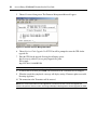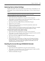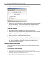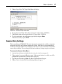
1
Emerge ECMS2000U
TM
Digital Workstation Extender
Installer/User Guide
For Technical Support:
www.avocent.com/support
Avocent Corporation
4991 Corporate Drive
Huntsville, Alabama 35805-6201
USA
Tel: +1 256 430 4000
Fax: +1 256 430 4031
Avocent Asia Pacific
Singapore Branch Office
100 Tras Street, #15-01
Amara Corporate Tower
Singapore 079027
Tel: +656 227 3773
Fax: +656 223 9155
Avocent International Ltd.
Avocent House, Shannon Free Zone
Shannon, County Clare, Ireland
Tel: +353 61 715 292
Fax: +353 61 471 871
Avocent Germany
Gottlieb-Daimler-Straße 2-4
D-33803 Steinhagen
Germany
Tel: +49 5204 9134 0
Fax: +49 5204 9134 99
Avocent Canada
20 Mural Street, Unit 5
Richmond Hill, Ontario
L4B 1K3 Canada
Tel: +1 877 992 9239
Fax: +1 877 524 2985
590-704-501A
USA Notification
Warning: Changes or modifications to this unit not expressly approved by the party responsible for compliance
could void the user’s authority to operate the equipment.
Note: This equipment has been tested and found to comply with the limits for a Class A digital device,
pursuant to Part 15 of the FCC Rules. These limits are designed to provide reasonable protection against
harmful interference when the equipment is operated in a commercial environment. This equipment generates,
uses and can radiate radio frequency energy and, if not installed and used in accordance with the instruction
manual, may cause harmful interference to radio communications. Operation of this equipment in a residential
area is likely to cause harmful interference in which case the user will be required to correct the interference at
his own expense.
Canadian Notification
This digital apparatus does not exceed the Class A limits for radio noise emissions from digital apparatus set
out in the Radio Interference Regulations of the Canadian Department of Communications.
Le présent appareil numérique n’émet pas de bruits radioélectriques dépassant les limites applicables aux
appareils numériques de la classe A prescrites dans le Règlement sur le brouillage radioélectrique édicté par le
Ministère des Communications du Canada.
Japanese Approvals
Safety and EMC Approvals and Markings
UL, FCC, cUL, ICES, CE, N, GS, IRAM, GOST, VCCI, MIC, C-Tick
Sound Level Measure
The measured sound level of this appliance is 44.7 dB(A).
Die arbeitsplatzbezogene Geräuschemission des Gerätes beträgt 44,7 dB(A).
Avocent EmergeΤΜ
ECMS2000U Digital
Workstation Extender
Installer/User Guide
Avocent, the Avocent logo and Emerge are registered trademarks of
Avocent Corporation. All other marks are the property of their respective
owners.
© 2006 Avocent Corporation. All rights reserved. 590-704-501A
Instructions
This symbol is intended to alert the user to the presence of important operating and maintenance
(servicing) instructions in the literature accompanying the appliance.
Dangerous Voltage
This symbol is intended to alert the user to the presence of uninsulated dangerous voltage within the
product’s enclosure that may be of sufficient magnitude to constitute a risk of electric shock to persons.
Power On
This symbol indicates the principal on/off switch is in the on position.
Power Off
This symbol indicates the principal on/off switch is in the off position.
Protective Grounding Terminal
This symbol indicates a terminal which must be connected to earth ground prior to making any other
connections to the equipment.
iv
TABL E OF CONTEN TS
List of Figures ................................................................................................................. vi
List of Tables ................................................................................................................. viii
Chapter 1: Product Overview.......................................................................................... 1
Features and Benefits ........................................................................................................................ 1
Safety Precautions ............................................................................................................................. 4
Chapter 2: Installation ..................................................................................................... 5
Getting Started ................................................................................................................................... 5
Needed to install the Avocent Emerge ECMS2000U Extender .................................................. 5
Needed for non-standard installations ....................................................................................... 5
Mounting Option................................................................................................................................ 5
Installation Options ........................................................................................................................... 6
Point-to-point installation .......................................................................................................... 6
Connecting Power ...................................................................................................................... 9
Networked Installation ............................................................................................................. 10
Chapter 3: Operations ................................................................................................... 13
Overview .......................................................................................................................................... 13
LED Identification .................................................................................................................... 13
Accessing the System ....................................................................................................................... 14
The Serial Menu............................................................................................................................... 14
Accessing the serial menu......................................................................................................... 14
Navigating the serial menu....................................................................................................... 16
Configuring Network Settings.......................................................................................................... 16
Detecting a Transmitter IP Address ................................................................................................ 23
Authentication .................................................................................................................................. 24
Flash Upgrading your Emerge Digital Workstation Extender........................................................ 28
Restoring Factory Default Settings.................................................................................................. 33
Resetting the Avocent Emerge ECMS2000U Extender.................................................................... 33
Viewing System Information ............................................................................................................ 34
Configuring Video Input Settings .................................................................................................... 36
Session Retry Settings ...................................................................................................................... 37
Audio Performance Settings ............................................................................................................ 38
Appendices..................................................................................................................... 41
v
Avocent Emerge ECMS2000U Extender Installer/User Guide
Appendix A: Technical Specifications ............................................................................................. 41
Appendix B: Factory Default Settings ............................................................................................. 46
Appendix C: Technical Support ....................................................................................................... 47
Appendix D: Troubleshooting.......................................................................................................... 48
vi
L IS T O F F IG URE S
List of Figures
Figure 1.1: Avocent Emerge ECMS2000U Extender - Basic System................................................ 1
Figure 2.1: Point-to-point Installation .............................................................................................. 6
Figure 2.2: Computer Access Node ................................................................................................... 8
Figure 2.3: User Access Node and Computer Access Node Installation .......................................... 9
Figure 2.4: Networked Installation ................................................................................................. 10
Figure 3.1: Com1 Properties........................................................................................................... 15
Figure 3.2: Appliance Selection Menu ............................................................................................ 16
Figure 3.3: Transmitter Main Menu................................................................................................ 17
Figure 3.4: Network Configuration Menu ....................................................................................... 17
Figure 3.5: Transmitter Network Configuration Menu ................................................................... 18
Figure 3.6: Receiver Main Menu..................................................................................................... 19
Figure 3.7: Network Configuration Menu ....................................................................................... 19
Figure 3.8: Transmitter Configuration Menu on the Receiver........................................................ 20
Figure 3.9: Receiver Main Menu..................................................................................................... 21
Figure 3.10: Network Configuration Menu ..................................................................................... 21
Figure 3.11: Receiver Network Configuration Menu ...................................................................... 22
Figure 3.12: Receiver Main Menu................................................................................................... 23
Figure 3.13: Network Configuration Menu ..................................................................................... 23
Figure 3.14: Transmitter IP Configuration Menu on the Receiver ................................................. 24
Figure 3.15: The Receiver Security Configuration Menu ............................................................... 25
Figure 3.16: Password Reset Mode................................................................................................. 26
Figure 3.17: Transmitter Security Configuration Menu ................................................................. 27
Figure 3.18: Transmitter Firmware Management Menu ................................................................ 29
Figure 3.19: Transmitter Firmware Management Menu ................................................................ 30
Figure 3.20: Receiver Firmware Management Menu ..................................................................... 31
Figure 3.21: Receiver Firmware Management Menu ..................................................................... 32
Figure 3.22: Receiver Reset Appliance Menu ................................................................................. 34
Figure 3.23: Appliance Information Menu...................................................................................... 35
Figure 3.24: Receiver Appliance Information Menu....................................................................... 35
Figure 3.25: Transmitter Console Settings Menu ........................................................................... 36
Figure 3.26: Transmitter Target Video Menu ................................................................................. 37
Figure 3.27: Session Retry Menu .................................................................................................... 38
List of Figures
vii
Figure 3.28: Transmitter Console Settings Menu ........................................................................... 39
Figure 3.29: Transmitter Audio Performance Menu....................................................................... 39
Figure 3.30: Receiver Console Settings Menu ................................................................................ 40
Figure 3.31: Receiver Audio Performance Menu............................................................................ 40
viii
L I S T OF T A B L ES
List of Tables
Table 2.1: Supported Video Resolutions and Refresh Rates ............................................................. 7
Table 2.2: Default network settings ................................................................................................. 10
Table 3.1: RJ-45 Connector LEDs .................................................................................................. 13
Table A.1: User Access Node Product Specifications ..................................................................... 41
Table A.2: Computer Access Node Product Specifications ............................................................. 44
Table B.1: Avocent Emerge ECMS2000U Extender ....................................................................... 46
ix
Avocent Emerge ECMS2000U Extender Installer/User Guide
1
CHA PTER
1
Product Overview
Features and Benefits
The Avocent EmergeTM ECMS2000U Extender provides users with a full computer desktop
experience from anywhere on the corporate TCP/IP network, while maintaining the computers
securely housed in a corporate data center. This desktop experience includes access for the desktop
user to keyboard, mouse, video and audio devices.
The Avocent Emerge ECMS2000U Extender consists of:
•
The Computer Access Node that connects externally to the remote computer
•
The User Access Node that is located at the user’s desk
Figure 1.1: Avocent Emerge ECMS2000U Extender - Basic System
2
Avocent Emerge ECMS2000U Extender Installer/User Guide
Computer Access Node
The Computer Access Node connects externally to the video, audio and USB ports of the
remote computer.
The Computer Access Node is attached directly to the remote computer and draws its power
directly from two USB ports on the remote computer. This removes the need for additional power
supply connections at the rack.
NOTE: If the remote computer cannot supply the required power or if two USB connections are not available, an
external power supply (part no. ECMS2000-PSU) can be obtained from Avocent.
The Computer Access Node captures, compresses and encrypts the computer’s media streams and
transmits them to the User Access Node over a standard TCP/IP network.
User Access Node
The User Access Node enables the desktop user’s keyboard, mouse, video, and audio devices to
connect to the Avocent Emerge ECMS2000U Extender. It is available as a desktop
user station.
Automatic connection
When the User Access Node is powered up, a connection is automatically established with the
remote computer via the Computer Access Node. No intervention is required from the user. See
Accessing the System on page 14.
Ethernet addressing
The User Access Node and the Computer Access Node are IP-addressable devices; this gives you
the flexibility to locate back-racked computers anywhere within your enterprise and at any distance
from your desktop users. The User Access Node and the Computer Access Node use standard
network protocols to transfer data streams between the remote computer and the peripheral devices
located at the user’s desk. The Avocent Emerge ECMS2000U Extender can operate on a network
connection of 100 Mbps or 1 Gbps. For optimum performance a 1 Gbps connection is
recommended. For more information see Chapter 2.
Multiplatform support
The Computer Access Node is connected to the remote computer via USB connectors. This enables
the Avocent Emerge ECMS2000U Extender to interoperate seamlessly with PC, Sun and
Macintosh target computers. PC, Sun and Macintosh USB keyboards can be connected to the User
Access Node. PS/2 keyboards and mice can also be used.
You can attach the Avocent Emerge ECMS2000U Extender to computers running the following
operating systems:
•
Microsoft WindowsTM
•
Red Hat Linux
Chapter 1: Product Overview
•
Solaris
•
MacOS
3
The default keyboard drivers for these operating systems are fully supported by the Avocent
Emerge ECMS2000U Extender.
Flexible installation
The Avocent Emerge ECMS2000U Extender provides you with the following flexible installation
options:
•
The User Access Node can be desk mounted or mounted on the back of a monitor
•
Installation requires no new drivers or software
•
Standard UTP cabling makes installation simple and keeps costs low
Security
The Avocent Emerge ECMS2000U Extender supports Secure Sockets Layer (SSL) over a TCP/IP
connection. All media streams transmitted between the User Access Node and the Computer
Access Node are encrypted. Password protection is also provided to control access to all
administration functions, such as network configuration. See Authentication on page 24.
Operations administration and maintenance
The User Access Node incorporates a serial menu that allows you to perform administration and
maintenance tasks for both the User Access Node and the Computer Access Node. Examples of
tasks you can perform include, configuration of network settings and firmware Flash upgrades. See
The Serial Menu on page 14.
Flash upgradeable
Upgrade your firmware at any time using the XMODEM or HTTP protocols to ensure that your
Avocent Emerge ECMS2000U Extender is always running the most current version available. Both
the Computer Access Node and the User Access Node are Flash upgradeable. See Flash Upgrading
your Emerge Digital Workstation Extender on page 28.
Support for keyboards and mice
USB and PS/2 keyboards and mice are fully supported by the Avocent Emerge ECMS2000U
Extender. The system also allows for mix and match of USB and PS/2 peripherals. For example, it
is possible to use a USB keyboard in conjunction with a PS/2 mouse. The default keyboard and
mouse drivers of the remote computer are fully supported. This enables the Avocent Emerge
ECMS2000U Extender to support 2-, 3- and 5-button mice with scroll- and tilt-wheel capability.
Composite mouse and keyboard devices are also supported.
4
Avocent Emerge ECMS2000U Extender Installer/User Guide
USB support
The Avocent Emerge ECMS2000U Extender is compatible with the USB 2.0 standard. The User
Access Node provides four USB 2.0 compliant ports that can be used to access USB keyboards,
mice and USB hubs. Hot-plugging of USB devices is supported.
NOTE: A hub cannot be used to expand the number of USB ports available.
Audio
The Avocent Emerge ECMS2000U Extender supports CD-quality stereo from the remote computer
to peripheral speakers, and mono-quality audio from a peripheral microphone to the remote
computer.
Video
Video of 24-bit color depth up to a resolution of 1280 x 1024 at 60 Hz is supported by the Avocent
Emerge ECMS2000U Extender. Both CRT and flat-panel LCD monitors are supported, and can be
connected to the Avocent Emerge ECMS2000U Extender via a DVI-I video connector. VGA
monitors can be attached to the system by using a DVI to VGA adaptor. The system supports DDC
version 2B.
Reduced Total Cost of Ownership (TCO)
The Avocent Emerge ECMS2000U Extender delivers significantly lower TCO when compared to
traditional distributed computer systems. Centralized maintenance enables greater security and
convenience as well as reduced workplace disruption and down-time. IT administration costs are
also significantly reduced by housing all PCs in one central location. Relocating the computer away
from the user frees up valuable office space and reduces desktop power and heating, ventilation and
air conditioning (HVAC) requirements.
Safety Precautions
To avoid potential video and/or keyboard problems when using Avocent products:
•
If the building has 3-phase AC power, ensure that the computer and monitor are on the same
phase. For best results, they should be on the same circuit.
To avoid potentially fatal shock hazard and possible damage to equipment, please observe the
following precautions:
•
Do not use a 2-wire extension cord in any Avocent product configuration.
•
Test AC outlets at the computer and monitor for proper polarity and grounding.
•
Use only with grounded outlets at both the computer and monitor. When using a backup
Uninterruptible Power Supply (UPS), power the computer and the Computer Access Node off
the same supply.
NOTE: The AC inlet is the main disconnect.
5
CHA PTER
2
Installation
Getting Started
Before installing your Avocent EmergeTM ECMS2000U Extender, refer to the list below to ensure
that you have all the items necessary for installation.
Needed to install the Avocent Emerge ECMS2000U Extender
•
User Access Node
•
Computer Access Node
•
External power supply for the User Access Node
•
IEC power cord
•
Avocent Emerge ECMS2000U Extender Quick Installation Guide
•
UTP cable (not supplied)
•
Three-wire serial cable or null modem cable (not supplied)
Needed for non-standard installations
To connect a VGA monitor to the User Access Node:
•
A DVI to VGA adaptor (not supplied)
To connect the Computer Access Node to a remote computer that has VGA video output:
•
A VGA to DVI-I adaptor (not supplied)
To connect the Computer Access Node to a remote computer that has DVI-D video output:
•
A DVI-D to DVI-I adaptor (not supplied)
To power the Computer Access Node if a remote computer does not have two available USB ports:
•
An EMCS2000-PSU power supply (not supplied)
Mounting Option
The User Access Node features the following mounting option that allows you to adapt easily to
most work environments:
6
Avocent Emerge ECMS2000U Extender Installer/User Guide
•
Mounting to the rear of a flat-panel monitor via a mounting plate accessory
NOTE: Mounting accessories are ordered separately. Contact Avocent for more information.
Installation Options
CAUTION:To reduce the risk of electric shock or damage to your equipment,
disconnect the power from the User Access Node by unplugging the power supply from the electrical outlet.
CAUTION:To reduce the risk of electric shock or damage to your equipment,
power up the remote computer and the User Access Node in the order described in the following procedures.
You can install the Avocent Emerge ECMS2000U Extender in one of two ways:
1.
Point-to-point
2.
Networked
Point-to-point installation
The following instructions will enable you to install your Avocent Emerge ECMS2000U Extender
in a point-to-point configuration. In a point-to-point configuration no administrator setup of the
Computer Access Node or the User Access Node is required. This enables you to install the system
quickly, directly out-of-the-box. However, if you choose the point-to-point configuration you can
install only one Computer Access Node and User Access Node pair on a subnet. If you use this
configuration you must also locate both the Computer Access Node and the User Access Node on
the same subnet.
Computer Access Node
User Access Node
Remote Computer
Figure 2.1: Point-to-point Installation
Chapter 2: Installation
7
To connect the Computer Access Node:
Before connecting the Computer Access Node to the remote computer, ensure that the resolution
and the refresh rate of the remote computer are supported by the Avocent Emerge ECMS2000U
Extender system. Set the screen resolution and refresh rate of the remote computer according to
Table A.1. Unsupported settings will cause blank video at the receiver.
NOTE: For new information on supported resolutions and refresh rates see www.avocent.com
1.
Power down the remote computer.
2.
The Computer Access Node has two USB connectors. Connect each of these connectors to a
corresponding USB port on the remote computer.
3.
Connect the video connector on the Computer Access Node to the appropriately labeled port
on the back of the computer.
NOTE: A VGA-only computer can be connected to the Computer Access Node using a VGA to DVI-I adaptor.
You must configure the Computer Access Node video settings for VGA through the serial menu.
For more information see Configuring Video Input Settings on page 36.
4.
Connect the Computer Access Node’s audio and microphone connectors to the appropriately
labeled ports on the back of the computer.
NOTE: For CD-quality audio, you must configure the Computer Access Node and the User Access Node using
the serial menu. For more information see Audio Performance Settings on page 38.
5.
Connect the UTP cable to the Computer Access Node’s RJ-45 connector.
6.
Power up the computer.
7.
Route the other end of the UTP cable to the location you have chosen for the User Access
Node. If necessary you can extend the UTP cable via junctions or a hub - subject to normal
Ethernet cabling practices.
The Computer Access Node draws electrical power from two USB ports on the remote computer.
One USB port is not sufficient to power the Computer Access Node. If you have only one USB port
on your remote computer, you will need to order an external power supply for the Computer Access
Node from Avocent.
8
Avocent Emerge ECMS2000U Extender Installer/User Guide
.
USB
Video
Mic
Line out
Figure 2.2: Computer Access Node
To connect the User Access Node:
1.
Connect your keyboard, monitor, mouse and other peripherals cables to the appropriately
labeled ports on the back of the User Access Node.
2.
Connect the UTP cable to the RJ-45 port on the back of the User Access Node.
3.
Power up the User Access Node. A connection will be automatically established with the
remote computer.
NOTE: VGA monitors can be connected to the User Access Node by using a DVI-I to VGA adaptor.
Chapter 2: Installation
Microphone
User Access Node
Speakers
External
Power
Supply
Serial
PS/2
Local Peripherals
attached via USB
Remote
PC
Computer Access Node
Figure 2.3: User Access Node and Computer Access Node Installation
Connecting Power
The User Access Node features an external power supply. A DC power jack is located on the rear
of the User Access Node.
NOTE: Use only the power supply provided by Avocent.
To connect power to the User Access Node:
1.
Plug the external power supply’s 2.5mm connector into the DC power jack on the rear of the
User Access Node.
2.
Connect the detachable IEC power cord to the power supply.
3.
Plug the IEC power cord into an appropriate wall outlet.
9
10
Avocent Emerge ECMS2000U Extender Installer/User Guide
Networked Installation
The following instructions will enable you to install your Avocent Emerge ECMS2000U Extender
in a networked configuration. In this installation, multiple Computer Access Nodes and User
Access Nodes are attached via the same Ethernet network. In this case, it is important for each unit
to be configured with a unique IP address.
Computer Access Nodes and User Access Nodes may be configured for use on a single subnet or
for use across routers. Use of routers, however, will cause a slight increase in end-to-end latencies,
which may not be acceptable for all applications.
Computer Access Node
User Access Node
Remote PC
Figure 2.4: Networked Installation
The Avocent Emerge ECMS2000U Extender has been pre-configured with factory-default network
settings. If you install only one Avocent Emerge ECMS2000U Extender on a subnet, you do not
need to change these default network settings. If you install multiple units on the same subnet, you
will need to assign a unique IP address to each unit. This can be done via the serial port. See The
Serial Menu on page 14.
Table 2.1: Default network settings
Component
IP Address
Type
Default
Gateway
Subnet Mask
User Access
Node
192.168.13.1
static
0.0.0.0
255.255.255.0
Computer
Access Node
192.168.13.2
static
0.0.0.0
255.255.255.0
Chapter 2: Installation
11
To install the Avocent Emerge ECMS2000U Extender on a network:
1.
Connect the Computer Access Node to the remote computer as described previously in Pointto-point installation on page 6. Connect one end of the UTP cable to the Computer Access
Node’s RJ-45 connector. Connect the other end of the UTP cable to the Ethernet network.
2.
Connect the User Access Node to the peripherals as described above in Point-to-point
installation on page 6. Use a length of UTP cable to connect the User Access Node to the
Ethernet network via the RJ-45 connector on the rear of the User Access Node.
3.
Power up the User Access Node. A connection will be automatically established with the
remote computer.
4.
Use the serial menu to re-configure the network settings for the Computer Access Node. For
more information on how to do this see, Configuring Network Settings on page 16.
NOTE: If the User Access Node and Computer Access Node are to be located on different subnets, configure
their network settings before you connect to the network.
NOTE: If there are already Computer Access Node/User Access Node pairs operating on the subnet, configure
network settings of new Computer Access Node/User Access Node pairs before connecting them to the network.
5.
Use the serial menu to re-configure the network settings for the User Access Node. For more
information on how to do this see, Configuring Network Settings on page 16.
6.
Repeat this procedure for each Computer Access Node and User Access Node pair you wish to
install on the network.
12
Avocent Emerge ECMS2000U Extender Installer/User Guide
13
CHA PTER
3
Operations
Overview
Operating a computer through the Avocent EmergeTM ECMS2000U Extender is no different than
working directly connected to your computer. All peripherals operate as if directly connected, even
though the computer is located at a distance. When you power up the User Access Node, a
connection is automatically established with the computer.
While the default settings of your Avocent Emerge ECMS2000U Extender will work with most
systems, you may choose to change settings to better fit your system. Internal settings such as
connection settings can be configured via the serial menu. See The Serial Menu on page 14. You
can also upgrade the Avocent Emerge ECMS2000U Extender via the serial menu.
LED Identification
Front panel
There are two blue LEDs on the front panel of the User Access Node. The PWR LED will light up
when the User Access Node has been powered up. The ACTIVE LED will blink slowly until the
User Access Node establishes a connection with the Computer Access Node. When a connection
has been established between the User Access Node and the Computer Access Node, the ACTIVE
LED will stop blinking and will remain lit.
Rear panel
Two LEDs are built into both the RJ-45 connector on the rear of the User Access Node, and into the
RJ-45 connector on the Computer Access Node. The following table illustrates their operation.
Table 3.1: RJ-45 Connector LEDs
LED
Indication
Meaning
LED 1
Green static
Linked at 1 Gbps
Green flashing
Linked at 100 Mbps
Green off
No Link
14
Avocent Emerge ECMS2000U Extender Installer/User Guide
Table 3.1: RJ-45 Connector LEDs (Continued)
LED 2
Yellow static
Linked but no activity
Yellow flashing
Transmit/receive activity
Accessing the System
When the User Access Node is powered up, it will automatically initiate a connection with the
remote computer.
To access the remote computer:
1.
Power up the User Access Node.
2.
A series of messages will be displayed on the screen to inform you of the progress
of the connection.
3.
You will be able to interact with the remote computer as if it were located at your desk.
NOTE: If the remote computer has been powered down, the User Access Node cannot establish a connection.
The Serial Menu
The User Access Node incorporates a serial menu that allows you to:
•
Configure network settings for the User Access Node
•
Configure network settings for the Computer Access Node
•
Set or change passwords
•
Upgrade your firmware for the User Access Node and Computer Access Node
•
Reset to factory defaults
•
Set a session time-out value
•
Change the audio performance settings
Accessing the serial menu
You can access the serial menu via the serial port on the back of the User Access Node. All terminal
commands are executed through a terminal or PC running HyperTerminal® emulation software
or equivalent.
NOTE: In this section of the manual the term “Transmitter” will be used to refer to the Computer Access Node.
NOTE: In this section of the manual the term “Receiver” will be used to refer to the User Access Node.
Chapter 3: Operations
15
By default, two passwords are required to access the Avocent Emerge ECMS2000U Extender via
the Receiver (User Access Node). One password controls access to the Receiver, the other
password controls access to the Transmitter (Computer Access Node). In both cases, the default
password is “password”. For information on how to change the default password, see
Authentication on page 24.
Items needed to access the serial menu
•
Networked computer with a serial port
•
Null-modem serial cable (male DB9) or three-wire serial cable
•
HyperTerminal emulation software or equivalent
To access the serial menu:
1.
Connect one end of the serial cable to the serial port on the back of the Receiver.
2.
Connect the other end of the serial cable to the serial port of your PC.
3.
Launch HyperTerminal.
4.
Configure the HyperTerminal session for 57600 bits per second, 8 data bits, no parity, 1 stop
bit and no flow control.
NOTE: Software (XON/XOFF) flow control is supported. However, it should not be used when using XMODEM.
Figure 3.1: Com1 Properties
5.
Confirm the HyperTerminal settings.
16
Avocent Emerge ECMS2000U Extender Installer/User Guide
6.
Press Enter to display the serial menu. The Appliance Selection Menu will be displayed.
Figure 3.2: Appliance Selection Menu
7.
Select Receiver or Transmitter. You will be prompted to enter a password.
8.
Type the password and press Enter.
NOTE: If there is no Transmitter connected to the Receiver, an error message will display and you will be
returned to the Appliance Selection Menu.
Navigating the serial menu
The serial menu is driven by a series of simple nested sub-menus. To navigate through the serial
menu, simply type the number or letter that corresponds to the option you wish to choose and press
Enter. This action will bring you to a sub-menu or to a screen where you can make configuration
changes. To exit a menu or screen and to confirm any configuration changes you have made, type 0
(zero) and press Enter. To navigate back up through the menus, continue to type 0 and press Enter
at each screen.
Configuring Network Settings
The Avocent Emerge ECMS2000U Extender is shipped with default network settings preconfigured for your Receiver and Transmitter. For more information see Networked Installation on
page 10. You can change the network settings (from the default values) for your system using the
serial menu. If you wish, you can place the Receiver on a different subnet from the Transmitter.
NOTE: Static addressing is the only IP addressing method supported.
NOTE: It is recommended that you configure the network settings for the Transmitter before you configure the
network settings for the Receiver.
Chapter 3: Operations
17
To configure network settings for the Transmitter:
1.
Activate the serial menu as described in Accessing the serial menu on page 14.
2.
Choose option 2 to access the Transmitter menu. If the password option is enabled, you will be
prompted for a password. See Authentication on page 24.
3.
Type the password and press Enter. The Transmitter Main Menu will appear.
Figure 3.3: Transmitter Main Menu
NOTE: The Reset option in the Transmitter Main Menu applies only to network settings.
4.
Choose Network Configuration. The Network Configuration Menu will appear.
Figure 3.4: Network Configuration Menu
18
Avocent Emerge ECMS2000U Extender Installer/User Guide
5.
Choose Transmitter Network Config. The Transmitter Network Configuration Menu
will appear.
Figure 3.5: Transmitter Network Configuration Menu
6.
Choose Transmitter IP Address.
7.
Type a valid IP address. Press Enter to return to the Transmitter Network Configuration Menu.
8.
Choose Transmitter Netmask.
9.
Type a valid Transmitter Netmask. Press Enter to return to the Transmitter Network
Configuration Menu.
10. Choose Transmitter Default Gateway.
11. Type a valid Transmitter Default Gateway. Press Enter to return to the Transmitter Network
Configuration Menu.
12. Type 0 (zero) and press Enter to return to the Network Configuration Menu.
13. If you made a mistake and do not wish to save the changes you made to the network settings
type C and press Enter.
14. To confirm your changes and apply those settings type 0 (zero) and press Enter.
15. A system message will appear that states “Connection to the Transmitter is lost”. You will be
automatically returned to the Appliance Selection Menu screen.
16. Choose option 1 to access the Receiver menu. If the password option is enabled, you will be
prompted for a password. See Authentication on page 24.
Chapter 3: Operations
17. Type the password and press Enter. The Receiver Main Menu will appear.
Figure 3.6: Receiver Main Menu
18. Choose Network Configuration. The Network Configuration Menu will appear.
Figure 3.7: Network Configuration Menu
19
20
Avocent Emerge ECMS2000U Extender Installer/User Guide
19. Choose Transmitter IP Config. The Transmitter IP Config menu will appear. The old
Transmitter IP address is displayed beside menu option 1.
Figure 3.8: Transmitter Configuration Menu on the Receiver
20. Choose Transmitter IP Address. Type the new IP address for the Transmitter. Press Enter to
return to the Transmitter IP Configuration Menu.
21. Type 0 (zero) and press Enter to return to the Network Configuration Menu.
22. If you made a mistake and do not wish to save the changes you made to the network settings
type C and press Enter.
23. To confirm your changes and apply those settings type 0 (zero) and press Enter.
24. The Receiver will now automatically reset to apply the new network configuration. You will be
automatically returned to the Appliance Selection Menu screen. The connection to the
Transmitter will be automatically restored.
To configure network settings for the Receiver:
1.
Activate the serial menu as described in Accessing the serial menu on page 14.
2.
Choose option 1 to access the Receiver menu. If the password option is enabled, you will be
prompted for a password. See Authentication on page 24.
Chapter 3: Operations
3.
Type the password and press Enter. The Receiver Main Menu will appear.
Figure 3.9: Receiver Main Menu
4.
Choose Network Configuration. The Network Configuration Menu will appear.
Figure 3.10: Network Configuration Menu
21
22
Avocent Emerge ECMS2000U Extender Installer/User Guide
5.
Choose Receiver Network Config. The Receiver Network Configuration Menu will appear.
The current network settings are visible here.
Figure 3.11: Receiver Network Configuration Menu
NOTE: The Reset option in the Receiver Network Configuration Menu applies only to network settings.
6.
Choose Receiver IP Address.
7.
Type a valid IP address. Press Enter to return to the Receiver Network Configuration Menu.
8.
Choose Receiver Netmask.
9.
Type a valid Receiver Netmask. Press Enter to return to the Receiver Network
Configuration Menu.
10. Choose Receiver Default Gateway.
11. Type a valid Receiver Default Gateway. Press Enter to return to the Receiver Network
Configuration Menu.
12. Type 0 (zero) and press Enter to return to the Network Configuration Menu.
13. If you made a mistake and do not wish to save the changes you made to the network settings
type C and press Enter.
14. To confirm your changes and apply those settings, type 0 (zero) and press Enter.
NOTE: Changes to network configurations are applied only after you exit the Network Configuration Menu
15. The Receiver will now automatically reset to apply the new network configuration. During
reset, the Receiver will drop its connection to the Transmitter. You will be automatically
returned to the Appliance Selection Menu screen. The connection will be restored.
Chapter 3: Operations
23
Detecting a Transmitter IP Address
In the event that you forget the IP address of a Transmitter, you can use the serial menu to detect the
IP address of a Transmitter that is connected to the Receiver.
To detect the IP address of a connected Transmitter:
1.
Power down the down the remote computer to which the Transmitter is attached.
NOTE: If the Transmitter receives its power from an external power supply, disconnect the Transmitter from that
external power supply.
1.
Choose option 1 to access the Receiver menu. If the password option is enabled, you will be
prompted for a password. See Authentication on page 24.
2.
Type the password and press Enter. The Receiver Main Menu will appear.
Figure 3.12: Receiver Main Menu
3.
Choose Network Configuration. The Network Configuration Menu will appear.
Figure 3.13: Network Configuration Menu
24
Avocent Emerge ECMS2000U Extender Installer/User Guide
4.
Choose Transmitter IP Config. The Transmitter IP Config menu will appear. The old
Transmitter IP address is displayed beside menu option 1.
Figure 3.14: Transmitter IP Configuration Menu on the Receiver
5.
Choose Detect Transmitter Address. The following message will be displayed, “Connect the
Transmitter and the Receiver, then power up the Transmitter.”
6.
Power up the Transmitter.
7.
The Receiver will detect the IP address of the connected Transmitter. The Transmitter IP
Configuration Menu will refresh, and the current IP address of the connected Transmitter will
be displayed beside menu option 1.
NOTE: The detected IP address of the connected Transmitter will not be automatically saved.
You must enter the detected IP address manually, by choosing Transmitter IP Address from the Transmitter IP
Configuration Menu.
Authentication
By default, two passwords are required to access the Avocent Emerge ECMS2000U Extender via
the serial menu. One password is for access to the serial menus that control the Receiver. The other
password is for access to the serial menus that control the Transmitter. In both cases, the default
password is “password”.
Authentication for the Receiver
You can change the password settings for the Receiver through the serial menu via the Receiver
Security Configuration Menu.
To access the Receiver Security Configuration Menu:
1.
Activate the serial menu as described in Accessing the serial menu on page 14.
2.
Choose option 1 to access the Receiver menu. If the password option is enabled, you will be
prompted for a password. See Authentication on page 24.
3.
Type the password and press Enter. The Receiver Main Menu will appear.
Chapter 3: Operations
4.
25
Choose Security Configuration. The Security Configuration Menu will appear.
Figure 3.15: The Receiver Security Configuration Menu
To disable or enable the Receiver password:
1.
Choose Console Password on the Security Configuration Menu and press Enter. If a password
had been enabled, this action will disable the password.
2.
If a password had been disabled, you will be prompted to enter a password.
3.
Type the new password and press Enter.
NOTE: Each password must consist of ASCII characters and contain between 6 and 64 characters.
4.
Confirm the new password. If successful, you will see a message stating that the password has
been changed.
5.
Press Enter.
6.
To save your changes and exit the menu, type 0 (zero) and press Enter.
To change the Receiver password:
1.
Choose Change Console Password on the Security Configuration Menu. You will be prompted
to enter your current password.
2.
Type your current password and press Enter. You will be prompted to enter the new password.
3.
Type the new password and press Enter.
NOTE: Each password must consist of ASCII characters and contain between 6 and 64 characters.
4.
Confirm the new password. If successful, you will see a message stating that the password has
been changed.
5.
Press Enter.
6.
To save your changes and exit the menu, type 0 (zero) and press Enter.
26
Avocent Emerge ECMS2000U Extender Installer/User Guide
If you lose your Receiver password:
If you lose your Receiver password, you can reset the system to the default password with the help
of Avocent Technical Support.
1.
Activate the serial menu as described in Accessing the serial menu on page 14.
2.
Choose option 1 to access the Receiver menu.
3.
You will be prompted to enter your current password.
4.
Type ?????? (six question marks) and press Enter. The serial menu will generate a code and
display it to you. The code is a 16 character hex sequence. The serial menu will also prompt
you to enter a Key.
Figure 3.16: Password Reset Mode
5.
Contact Avocent Technical Support to obtain the Key. The Technical Support Specialist will
ask you for the 16 character hex code. Read out the code exactly as it appears on the serial
menu. The Technical Support Specialist will now give you another 16 character hex sequence.
6.
In the serial menu at the Key prompt, type the 16 character hex sequence provided to you by
Avocent Technical Support. Press Enter.
7.
The default password is now active.
For information on how to change your password, see Authentication for the Receiver on page 24.
Authentication for the Transmitter
You can change the password settings for the Transmitter through the serial menu using the
Transmitter Security Configuration Menu.
To access the Transmitter Security Configuration Menu:
1.
Activate the serial menu as described in Accessing the serial menu on page 14.
2.
Choose option 2 to access the Transmitter menu. If the password option is enabled, you will be
prompted for a password. See Authentication on page 24.
3.
Type the password and press Enter. The Transmitter Main Menu will appear.
Chapter 3: Operations
4.
27
Choose Security Configuration. The Security Configuration Menu will appear.
Figure 3.17: Transmitter Security Configuration Menu
To disable or enable the Transmitter password:
1.
Choose Console Password on the Security Configuration Menu and press Enter. If a password
has been enabled, this action will disable the password.
2.
If a password has been disabled, you will be prompted to enter a password.
3.
Type the new password and press Enter.
NOTE: Each password must consist of ASCII characters and contain between 6 and 64 characters.
4.
Confirm the new password. If successful, you will see a message stating that the password has
been changed.
5.
Press Enter.
6.
To save your changes and exit the menu, type 0 (zero) and press Enter.
To change the Transmitter password:
1.
Choose Change Console Password on the Security Configuration Menu. You will be prompted
to enter your current password.
2.
Type your current password and press Enter. You will be prompted to enter the new password.
3.
Type the new password and press Enter.
NOTE: Each password must consist of ASCII characters and contain between 6 and 64 characters.
4.
Confirm the new password. If successful, you will see a message stating that the password has
been changed.
5.
Press Enter.
6.
To confirm the new password and exit the screen, type 0 (zero) and press Enter.
28
Avocent Emerge ECMS2000U Extender Installer/User Guide
If you lose your Transmitter password:
If you lose your Transmitter password, you can reset the system to the default password with the
help of Avocent Technical Support.
1.
Activate the serial menu as described in Accessing the serial menu on page 14.
2.
Choose option 2 to access the Transmitter menu.
3.
You will be prompted to enter your current password.
4.
Type ?????? (six question marks) and press Enter. The serial menu will generate a code and
display it to you. The code is a 16 character hex sequence. The serial menu will also prompt
you to enter a Key.
5.
Contact Avocent Technical Support to obtain the Key. The Technical Support Specialist will
ask you for the 16 character hex code. Read out the code exactly as it appears on the serial
menu. The Technical Support Specialist will now give you another 16 character hex sequence.
6.
In the serial menu at the Key prompt, type the 16 character hex sequence provided to you by
Avocent Technical Support. Press Enter.
7.
The default password is now active.
For details on how to change your password see Authentication for the Transmitter on page 26.
Flash Upgrading your Emerge Digital Workstation Extender
You can Flash upgrade your Receiver and Transmitter. You can Flash upgrade your Avocent
Emerge ECMS2000U Extender using either XMODEM or HTTP. The Receiver and Transmitter
are upgraded separately using individual upgrade files. The upgrade files are supplied by Avocent.
For optimum system performance keep your firmware versions current.
NOTE: Do not use software (XON/XOFF) flow control when using XMODEM.
NOTE: It is recommended that you flash upgrade the Transmitter before you flash upgrade the Receiver.
To Flash upgrade your Transmitter using XMODEM:
1.
Download the Transmitter upgrade file from Avocent.
2.
Activate the serial menu as described in Accessing the serial menu on page 14.
3.
Choose option 2 to access the Transmitter menu. If the password option is enabled, you will be
prompted for a password. See Authentication on page 24.
4.
Type the password and press Enter. The Transmitter Main Menu will appear.
Chapter 3: Operations
5.
29
Choose Firmware Management. The Firmware Management Menu will appear.
Figure 3.18: Transmitter Firmware Management Menu
6.
Choose Transmitter Flash Upgrade Via XMODEM.
7.
Specify the location of the upgrade file and initiate the file transfer.
8.
When the transfer has completed, a message will display stating “Firmware update successful.
Resetting Appliance...” During reset the Transmitter will drop the connection to the Receiver.
A second system message will appear that states “Connection to the Transmitter is lost”. You
will be automatically returned to the Appliance Selection Menu screen.
NOTE: If the Transmitter determines that the upgrade file is invalid, the Transmitter cancels the upgrade and
maintains the previous firmware version. A message displays indicating that the upgrade has failed.
To Flash upgrade your Transmitter using HTTP:
1.
Download the Transmitter upgrade file from Avocent.
2.
Activate the serial menu as described in Accessing the serial menu on page 14.
3.
Choose option 2 to access the Transmitter menu. If the password option is enabled, you will be
prompted for a password. See Authentication on page 24.
4.
Type the password and press Enter. The Transmitter Main Menu will appear.
30
Avocent Emerge ECMS2000U Extender Installer/User Guide
5.
Choose Firmware Management. The Firmware Management Menu will appear.
Figure 3.19: Transmitter Firmware Management Menu
6.
Choose Transmitter Flash Upgrade Via HTTP. You will be prompted to enter the URL for the
upgrade file.
7.
Enter the URL for the upgrade file using the following syntax:
http://<server ip address>[:server port]/<upgrade file path>
For example:
http://192.168.0.1:8080/TX.dld
NOTE: If the server is set up on standard port 80, the port information can be omitted.
8.
To initiate the file transfer press Enter. The connection to the Transmitter will be dropped.
9.
When the transfer has completed, a message will display stating “Firmware update successful.
Resetting Appliance...” During reset the Transmitter will drop the connection to the Receiver.
A second system message will appear that states “Connection to the Transmitter is lost”. You
will be automatically returned to the Appliance Selection Menu screen.
NOTE: If the Transmitter determines that the upgrade file is invalid, the Transmitter cancels the upgrade and
maintains the previous firmware version. A message displays indicating that the upgrade has failed.
To Flash upgrade your Receiver using XMODEM:
1.
Download the Receiver upgrade file from Avocent.
2.
Activate the serial menu as described in Accessing the serial menu on page 14.
3.
Choose option 1 to access the Receiver menu. If the password option is enabled, you will be
prompted for a password. See Authentication on page 24.
4.
Type the password and press Enter. The Receiver Main Menu will appear.
Chapter 3: Operations
5.
31
Choose Firmware Management. The Firmware Management Menu will appear.
Figure 3.20: Receiver Firmware Management Menu
6.
Choose Receiver Flash Upgrade Via XMODEM. The connection to the Transmitter
will be dropped.
7.
Specify the location of the upgrade file and initiate the file transfer.
8.
When the transfer has completed, a message will display stating “Firmware update successful.
Resetting Appliance...”
9.
The connection to the Receiver will be restored.
NOTE: If the Receiver determines that the upgrade file is invalid, the Receiver cancels the upgrade and
maintains the previous firmware version. A message will display indicating that the firmware upgrade has failed.
To Flash upgrade your Receiver using HTTP:
1.
Download the Receiver upgrade file from Avocent.
2.
Activate the serial menu as described in Accessing the serial menu on page 14.
3.
Choose option 1 to access the Receiver menu. If the password option is enabled, you will be
prompted for a password. See Authentication on page 24.
4.
Type the password and press Enter. The Receiver Main Menu will appear.
32
Avocent Emerge ECMS2000U Extender Installer/User Guide
5.
Choose Firmware Management. The Firmware Management Menu will appear.
Figure 3.21: Receiver Firmware Management Menu
6.
Choose Receiver Flash Upgrade Via HTTP. You will be prompted to enter the URL for the
upgrade file.
7.
Enter the URL for the upgrade file using the following syntax:
http://<server ip address>[:server port]/<upgrade file path>
For example:
http://192.168.0.1:8080/RX.dld
NOTE: If the server is set up on standard port 80, the port information can be omitted.
8.
To initiate the file transfer press Enter. The connection to the Transmitter will be dropped.
9.
When the transfer has completed, a message will display stating “Firmware update successful.
Resetting Appliance...”
10. The connection to the Transmitter will be restored.
NOTE: If the Receiver determines that the upgrade file is invalid, the Receiver cancels the upgrade and
maintains the previous firmware version. A message will display indicating that the firmware upgrade has failed.
Chapter 3: Operations
33
Restoring Factory Default Settings
The serial menu enables you to easily restore the factory default settings of both the Receiver and
the Transmitter. To view a full list of the factory default settings, see Factory Default Settings on
page 46.
NOTE: Restoring factory default settings will also reset network settings. Before restoring factory default
settings, assess whether this is likely to cause conflicts with other devices on the network.
To restore the Receiver factory default settings:
1.
Activate the serial menu as described in Accessing the serial menu on page 14.
2.
Choose option 1 to access the Receiver menu. If the password option is enabled, you will be
prompted for a password. See Authentication on page 24.
3.
Type the password and press Enter. The Receiver Main Menu will appear.
4.
Choose Restore Factory Defaults.
5.
The Receiver will now automatically reset. You will be automatically returned to the
Appliance Selection Menu screen.
6.
During reset the Receiver will drop the connection to the Transmitter. When reset is complete
the Receiver will restore the connection to the Transmitter using the new settings.
To restore the Transmitter factory default settings:
1.
Activate the serial menu as described in Accessing the serial menu on page 14.
2.
Choose option 2 to access the Transmitter menu. If the password option is enabled, you will be
prompted for a password. See Authentication on page 24.
3.
Type the password and press Enter. The Transmitter Main Menu will appear.
4.
Choose Restore Factory Defaults.
5.
The Transmitter will now automatically reset. During reset the Transmitter will drop the
connection to the Receiver. A system message will appear that states “Connection to the
Transmitter is lost”. You will be returned to the Appliance Selection Menu screen. The
connection to the Receiver will be restored.
Resetting the Avocent Emerge ECMS2000U Extender
To reset the Receiver:
1.
Activate the serial menu as described in Accessing the serial menu on page 14.
2.
Choose option 1 to access the Receiver menu. If the password option is enabled, you will be
prompted for a password. See Authentication on page 24.
3.
The Receiver Main Menu will appear.
34
Avocent Emerge ECMS2000U Extender Installer/User Guide
4.
Choose Reset Appliance. The Reset Appliance Menu will appear.
Figure 3.22: Receiver Reset Appliance Menu
5.
Choose Receiver Reset to initiate the reset. A message will be displayed on the serial menu that
states “Resetting appliance...”. During reset the connection to the Transmitter is dropped.
When the reset is complete, you will be automatically returned to the Appliance Selection
Menu. The connection to the Transmitter will be automatically restored.
To reset the Transmitter:
1.
Activate the serial menu as described in Accessing the serial menu on page 14.
2.
Choose option 2 to access the Transmitter menu. If the password option is enabled, you will be
prompted for a password. See Authentication on page 24.
3.
The Transmitter Main Menu will appear.
4.
Choose Reset Appliance. The Reset Appliance Menu will appear.
5.
Choose Transmitter Reset to initiate the reset. A message will be displayed on the serial menu
that states “Resetting appliance...”. During reset the Transmitter will drop the connection to the
Receiver. A second system message will appear that states “Connection to the Transmitter is
lost.” You will be automatically returned to the Appliance Selection Menu screen. The
connection will be automatically restored.
Viewing System Information
The serial menu enables you to display the firmware release and details of the Receiver and of
the Transmitter.
To view Receiver system information:
1.
Activate the serial menu as described in Accessing the serial menu on page 14.
2.
Choose option 1 to access the Receiver menu. If the password option is enabled, you will be
prompted for a password. See Authentication on page 24.
3.
Type the password and press Enter. The Receiver Main Menu will appear.
Chapter 3: Operations
4.
35
Choose Appliance Information. The Appliance Information Menu will appear.
Figure 3.23: Appliance Information Menu
5.
Choose Receiver Appliance Information. The Receiver Appliance Information Menu
will appear.
The Receiver Appliance Information Menu screen contains the following information: Receiver
name; EID number; release version; application; boot and FPGA firmware version numbers; and
the manufacturing part number. All values are read-only.
Figure 3.24: Receiver Appliance Information Menu
To view Transmitter system information:
1.
Activate the serial menu as described in Accessing the serial menu on page 14.
2.
Choose option 2 to access the Transmitter menu. If the password option is enabled, you will be
prompted for a password. See Authentication on page 24.
3.
Type the password and press Enter. The Transmitter Main Menu will appear.
4.
Choose Appliance Information. The Appliance Information Menu will appear.
36
Avocent Emerge ECMS2000U Extender Installer/User Guide
5.
Choose Transmitter Appliance Information. The Transmitter Appliance Information Menu
will appear.
The Transmitter Appliance Information Menu screen contains the following information:
Transmitter name; EID number; release version; application; boot and FPGA firmware version
numbers; and the manufacturing part number. All values are read-only.
Configuring Video Input Settings
The Avocent Emerge ECMS2000U Extender system is capable of transmitting either digital (DVI)
or analog video (VGA) from the remote computer to your monitor. To enable the system to
transmit the appropriate video signal for your monitor, you must first configure the video input
settings for the Transmitter.
NOTE: Video-display problems may occur if video input settings are not configured correctly,
1.
Activate the serial menu as described in Accessing the serial menu on page 14.
2.
Choose option 2 to access the Transmitter menu. If the password option is enabled, you will be
prompted for a password. See Authentication on page 24.
3.
Type the password and press Enter. The Transmitter Main Menu will appear.
4.
Choose Console Settings. The Console Settings Menu will display. The current video input
setting is displayed beside menu item 1. Target Video
Figure 3.25: Transmitter Console Settings Menu
Chapter 3: Operations
5.
37
Choose Target Video. The Target Video Menu will display.
Figure 3.26: Transmitter Target Video Menu
6.
To toggle between DVI or VGA, choose menu item 1. Target Video - DVI/VGA.
7.
The updated setting will be displayed beside 1. Target Video - DVI/VGA.
8.
To save your changes and exit the menu, type 0 (zero) and press Enter.
The unit resets after you press Enter.
Session Retry Settings
The Avocent Emerge ECMS2000U Extender is designed to automatically establish a connection
between the Receiver and the remote computer. By default, if the Receiver cannot immediately
establish a connection with the remote computer it will retry once per second until a connection is
successfully established. You can change the default session retry settings using the serial menu.
To access the Session Retry Menu:
1.
Activate the serial menu as described in Accessing the serial menu on page 14.
2.
Choose option 1 to access the Receiver menu. If the password option is enabled, you will be
prompted for a password. See Authentication on page 24.
3.
Type the password and press Enter. The Receiver Main Menu will appear.
4.
Choose Console Settings. The Console Settings Menu will appear.
38
Avocent Emerge ECMS2000U Extender Installer/User Guide
5.
Choose Session Retry. The Session Retry Menu will appear.
Figure 3.27: Session Retry Menu
To change the retry settings:
1.
Access the Session Retry Menu via the serial menu as described above.
2.
To change the time interval between retry attempts, choose Session Retry Timeout Seconds.
You will be prompted to enter a new timeout value in SS (seconds) format.
3.
Type a value between 1 and 60 (inclusive) and press Enter.
4.
To confirm your selection and exit the screen, type 0 (zero) and press Enter.
Audio Performance Settings
You can use this option to modify the audio performance settings or to disable audio support. There
are three settings available: high, medium and off. The high setting provides the best audio
performance and should be used when high network bandwidth is available. The medium setting
should be used if network bandwidth is limited or if the network latency is high. If you choose off
audio support will be disabled.
NOTE: To ensure that audio operates correctly, configure the Receiver and the Transmitter with identical audio
performance settings.
To change the audio performance setting for the Transmitter:
1.
Activate the serial menu as described in Accessing the serial menu on page 14.
2.
Choose option 2 to access the Transmitter menu. If the password option is enabled, you will be
prompted for a password. See Authentication on page 24.
3.
Type the password and press Enter. The Transmitter Main Menu will appear.
Chapter 3: Operations
4.
39
Choose Console Settings. The Console Settings Menu will appear. The current audio
performance setting is displayed beside menu item 2. Audio Performance.
Figure 3.28: Transmitter Console Settings Menu
5.
Choose Audio Performance. The Audio Performance Menu will appear.This menu shows you
the audio settings that you can choose from. The current setting is indicated by an
asterisk symbol *
Figure 3.29: Transmitter Audio Performance Menu
6.
Type the number that corresponds to the audio setting you wish to apply and press Enter.
NOTE: If you choose “off,” audio support will be disabled.
7.
To confirm your selection and exit the screen, type 0 (zero) and press Enter. The unit resets
after you press Enter.
40
Avocent Emerge ECMS2000U Extender Installer/User Guide
To change the audio performance setting for the Receiver:
1.
Activate the serial menu as described in Accessing the serial menu on page 14.
2.
Choose option 1 to access the Receiver menu. If the password option is enabled, you will be
prompted for a password. See Authentication on page 24.
3.
Type the password and press Enter. The Receiver Main Menu will appear.
4.
Choose Console Settings. The Console Settings Menu will appear. The current audio
performance setting is displayed beside menu item 4. Audio Performance.
Figure 3.30: Receiver Console Settings Menu
5.
Choose Audio Performance. The Audio Performance Menu will appear.This menu shows you
the audio settings that you can choose from. The current setting is indicated by an asterisk *
Figure 3.31: Receiver Audio Performance Menu
6.
Type the number that corresponds to the audio setting you wish to apply and press Enter.
NOTE: If you choose “off,” audio support will be disabled.
7.
To confirm your selection and exit the screen, type 0 (zero) and press Enter. The unit resets
after you press Enter.
41
A P P EN D IC ES
Appendices
Appendix A: Technical Specifications
During the course of this product’s lifetime, modifications might be made to its hardware or
firmware that could cause these specifications to change without notice.
Table A.1: User Access Node Product Specifications
Network
Ethernet Standard
Ethernet II
IP Port Usage
Port 16384 - Video
Port 16385 - Audio
Port 16386 - Keyboard\Mouse
Ports 4463, 4464, 4465 - Control
Extension Ports
Number
1
Connectors
RJ-45
User Ports
Number
PS/2: 2; USB: 4; DVI-I video: 1; audio microphone: 1; audio line
out: 1; power jack: 1
Type
PS/2, USB Type A, DVI-I video
Connectors
6-pin miniDIN, PS/2 keyboard and mouse; USB Type A, USB
keyboard and mouse; DVI-I, female; 3.5 mm stereo audio
jacks, line out and mic; 2.5 mm DC power jack.
Encryption
Type
Authenticated SSL
Console Port
Number
1
Type
Three-wire Serial interface: RX, TX, GND via 16450-compatible
UART
Connectors
9-pin D-Shell (DB9)
42
Avocent Emerge ECMS2000U Extender Installer/User Guide
Table A.1: User Access Node Product Specifications (Continued)
Dimensions
HxWxD
26.5 x 210 x 130 mm (1.04 x 8.27 x 5.12 in)
Weight
0.7 Kg (1.54 lb)
without packaging, cables, power supply and literature
Environmental
Heat Dissipation
22 W/H
Power Consumption
20 W (including power supplied to USB ports)
AC-input power
100-240 V AC
AC-input current rating
1A
AC-frequency
50/60 Hz
Operating Temperature
0° to 35° Celsius (32° to 95° Farenheit)
Storage Temperature
-20° to 60° Celsius (-4° to 140° Farenheit)
Transit Temperature
-30° to 60° Celsius (-22° to 140° Farenheit)
Operating Humidity
10 to 90% noncondensing
Storage Humidity
5 to 95%
Supported Hardware
Peripherals
PS/2 keyboard and mouse, USB keyboard and mouse,
speakers, microphone
Keyboard
Standard 104/105/109 keyboards for PC, Macintosh, and Sun
USB keyboards for PC, Macintosh and Sun
Default keyboard drivers are fully supported for Microsoft
Windows, MacOS, Solaris and Red Hat Linux
Mouse
2-, 3-, and 5-button; scroll and tilt wheel
Appendices
Table A.1: User Access Node Product Specifications (Continued)
Video Resolution
640 x 350 @ 85 Hz
640 x 480 @ 60 Hz
640 x 480 @ 72 Hz
640 x 480 @ 75 Hz
640 x 480 @ 85 Hz
720 x 400 @ 70 Hz
720 x 400 @ 85 Hz
800 x 600 @ 60 Hz
800 x 600 @ 72 Hz
800 x 600 @ 75 Hz
800 x 600 @ 85 Hz
1024 x 768 @ 60 Hz
1024 x 768 @ 70 Hz
1024 x 768 @ 75 Hz
1024 x 768 @ 85 Hz
1152 x 864 @ 75 Hz
1280 x 960 @ 60 Hz
1280 x 1024 @ 60 Hz
Check www.avocent.com for the latest list of supported video
resolutions and refresh rates.
Video Standard
DDC version 2B
Color Depth
24 Bit
Audio Standard
PC99
Audio Performance
High Performance
Line out:
44.1 kHz over stereo channels at a resolution of 16 bits
Microphone:
44.1 kHz over a single channel at a resolution of 16 bits
Medium Performance
Line out:
8 kHz over stereo channels at a resolution of 16 bits
Microphone:
8 kHz over a single channel at a resolution of 16 bits
Target Sync Types
(Analog output only)
Separate horizontal and vertical
Safety and
EMC Approvals and
Markings
UL, FCC, cUL, CE
43
44
Avocent Emerge ECMS2000U Extender Installer/User Guide
Table A.2: Computer Access Node Product Specifications
Network
Ethernet Standard
Ethernet II
Extension Ports
Number
1
Connectors
RJ-45
Console Ports
Number
USB: 2; DVI-I video: 1; audio microphone: 1; audio line out: 1
Type
USB Type A, DVI-I video
Connectors
USB, male; DVI-I, male; 3.5 mm stereo audio jacks, line out
and mic; 2.5 mm DC power jack.
Encryption
Type
Authenticated SSL
Dimensions
HxWxD
68 x 21 x 153 mm (2.68 x 0.83 x 6.02 in)
Weight
0.3 Kg (0.66 lb) including cables
Environmental
Heat Dissipation
22 W/H
Power Consumption
6W
AC-input power
100-240 V AC
AC-input current rating
1A
AC-frequency
50/60 Hz
DC-input power
5V
DC-input current rating
1.1 A
Operating Temperature
0° to 35° Celsius (32° to 95° Farenheit)
Storage Temperature
-20° to 60° Celsius (-4° to 140° Farenheit)
Transit Temperature
-30° to 60° Celsius (-22° to 140° Farenheit)
Operating Humidity
10 to 90% noncondensing
Storage Humidity
5 to 95%
Appendices
Table A.2: Computer Access Node Product Specifications (Continued)
Supported Hardware
Video Resolution
CRT 1280 x 1024 @ 60 Hz
LCD 1280 x 1024 @ 60 Hz
Video Standard
DDC version 2B
Color Depth
24 Bit
Audio Standard
PC99
Audio Sampling
44.1 kHz over a single channel at a resolution of 16 bits
Target Sync Types
(Analog input only)
Separate horizontal and vertical
Safety and
EMC Approvals and
Markings
UL, FCC, cUL, CE
45
46
Avocent Emerge ECMS2000U Extender Installer/User Guide
Appendix B: Factory Default Settings
Table B.1: Avocent Emerge ECMS2000U Extender
User Access Node
Name
RX_<MAC address>
IP Address
192.168.13.1
Default Gateway
0.0.0.0
Netmask
255.255.255.0
OSD Hotkey Sequence
PRINT SCREEN
OSD Inactivity Timer
00 hours 10 minutes
OSD Inactivity Check
Box
Enabled
Session Inactivity Timer 00 hours 10 minutes
Session Inactivity
Check Box
Disabled
Session Retry Timeout
1 second
Audio Performance
Medium
Network Speed
Auto-Negotiate
Password
‘password’
Computer Access Node
Name
TX_<MAC address>
IP Address
192.168.13.2
Default Gateway
0.0.0.0
Netmask
255.255.255.0
Audio Performance
Medium
Network Speed
Auto-Negotiate
Password
‘password’
Video
DVI
Appendices
47
Appendix C: Technical Support
Our Technical Support staff is ready to assist you with any installation or operating issues you
encounter with your Avocent product. If an issue should develop, follow the steps below for the
fastest possible service.
To resolve an issue:
1.
Check the pertinent section of this manual to see if the issue can be resolved by following the
procedures outlined.
2.
Check our web site at www.avocent.com/support to search the knowledge base or use the online service request.
3.
Call the Avocent Technical Support location nearest you.
Please have the product serial number available when contacting Avocent Technical Support.
48
Avocent Emerge ECMS2000U Extender Installer/User Guide
Appendix D: Troubleshooting
No power status light on User Access Node
•
Verify that the power supply is plugged in correctly.
•
Ensure that the power cable from the Avocent-supplied power supply is securely plugged into
the User Access Node.
No video on monitor attached to User Access Node
•
Verify that the monitor attached to the User Access Node has power.
•
Ensure that the video cable from the monitor is securely plugged in to the correct connector on
the User Access Node.
•
Verify that the remote computer is powered.
•
Confirm that a network connection exists between the Computer Access Node and User
Access Node.
•
Confirm that the IP address used by the Computer Access Node has not been assigned to a second device on the network.
•
Confirm that the IP address used by the User Access Node has not been assigned to a second
device on the network.
•
Verify that the Computer Access Node is drawing sufficient power from the USB connections
on the remote computer and that it has booted correctly:
•
•
If the green LED on the Computer Access Node is on, the Computer Access Node is drawing sufficient power.
•
If the Computer Access Node cannot draw sufficient power from the remote computer you
will need to obtain an external power supply unit for the Computer Access Node from
Avocent. If connected through a USB hub, ensure that the hub can supply enough power.
Verify that the correct video setting has been configured in the Computer Access Node
serial menu:
•
If the remote computer provides DVI only video, verify that the Computer Access Node
serial menu has been configured for DVI. Then restart the remote computer.
•
If the remote computer provides VGA only video, verify that the Computer Access Node
serial menu has been configured for VGA. Then restart the remote computer.
•
The Computer Access Node has an internal fan. Verify that the fan is functioning.
•
Cycle power to the User Access Node. An informational message should appear on the monitor for a brief moment. If the message does not appear, check the monitor by plugging the
video cable from the monitor directly into the remote computer to verify that the monitor is
working and that the remote computer is generating active video. If this is functioning, check
that the display settings for your remote computer are set no higher than a resolution of 1280 x
1024 at 60 Hz refresh rate. If the monitor does not function correctly, replace it.
Appendices
•
49
If the Computer Access Node has been power cycled (by unplugging the USB cables), ensure
that all other cables are disconnected before reconnecting the Computer Access Node. Ensure
that you connect the USB cables first.
No mouse or keyboard operation from peripherals attached to
User Access Node
•
Ensure that the mouse and keyboard cables are connected to the correct PS/2 or USB ports on
the User Access Node. Match the connector color codes (green for mouse and purple for
keyboard).
•
Ensure that both of the USB connectors from the Computer Access Node are securely connected to the correct connectors on the remote computer.
•
If the remote computer can provide only one USB port for the Computer Access Node:
•
Use an external power supply for the Computer Access Node
•
Ensure that the Computer Access Node USB cable labeled “2” is attached to the available
USB port of the remote computer
•
Ensure that the correct keyboard layout is configured on the remote computer for the keyboard
you are using.
•
Retest the mouse and keyboard by connecting them directly to the remote computer and rebooting. If one does not function correctly, replace it.
No audio from speakers attached to User Access Node
•
Ensure that the audio cable is securely plugged into the line-out port of the remote computer
(should be color-coded green).
•
Ensure that the speaker cable is securely plugged into the line-out port of the
User Access Node.
•
Verify that the audio sample rate has not been set to “off” for either the Computer Access Node
or the User Access Node. See Audio Performance Settings on page 38.
•
Ensure that the same audio sample rate has been set for both the Computer Access Node and
the User Access Node. See Audio Performance Settings on page 38.
•
Verify that the speakers are powered.
•
Retest the speakers by connecting them directly to the remote computer. If they do not function
correctly, replace them.
Poor sound quality from speakers attached to User Access Node
4.
Ensure that the same audio sample rate has been set for both the Computer Access Node and
the User Access Node. See Audio Performance Settings on page 38.
Poor video quality on monitor attached to User Access Node
•
Reset video by pressing <F11>.
50
Avocent Emerge ECMS2000U Extender Installer/User Guide
•
Ensure that the video cable from the monitor is securely plugged in to the correct connector on
the User Access Node.
•
Check the video quality using a different monitor.
Connection to remote computer is lost
•
Verify that the network cable is securely connected to the RJ-45 connector at the rear of the
User Access Node.
•
Verify that the User Access Node is linked to the network and that it is receiving data. See LED
Identification on page 13.
•
Verify that the remote computer is powered.
•
Ensure that both of the USB connectors from the Computer Access Node are securely connected to the correct connectors on the remote computer.
•
Verify that the Computer Access Node is drawing sufficient power from the USB connections
on the remote computer and that it has booted correctly:
•
If the green LED on the Computer Access Node is on, the Computer Access Node is drawing sufficient power.
•
If the Computer Access Node cannot draw sufficient power from the remote computer,
obtain an external power supply unit for the Computer Access Node from Avocent.
•
The Computer Access Node has an internal fan. Verify that the fan is functioning.
•
Ping the Computer Access Node from another PC on the network to ensure it is connected.
•
Reset the Computer Access Node. See Resetting the Avocent Emerge ECMS2000U Extender
on page 33.
•
Reset the User Access Node. See Resetting the Avocent Emerge ECMS2000U Extender on
page 33.
•
Verify that the Ethernet network is fully operational.
Emerge ECMS2000U
TM
Digital Workstation Extender
YSOL
YS Solutions Co., Ltd.
YS Solutions Co.,Ltd.
TOKYO
Kouji-machi Tsuruya Hachiman Blug.6F, 2-4,Koujimachi,
Chiyoda-ku, Tokyo 102-0083 Japan
Tel:+81-3-5212-3521 Fax:+81-3-5212-3524
OSAKA
Nishi-Nakajima Shin-Osaka Blug.611, 5-10-5,NIshi-Nakajima,
Yodogawa-ku, Osaka 532-0011 Japan
Tel:+81-6-4806-7088 Fax:+81-6-6300-0122
E-mail:[email protected]
URL:http://www.ysol.co.jp
590-386-001A
Installer/User Guide