1
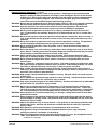
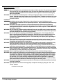
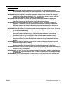
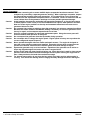
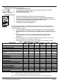
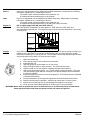
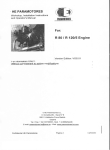
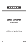
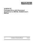
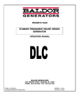
PC32Ri and PC43Ri
Portable Generator
Installation & Operating Manual
5/05
MN2403
WARNING:
CALIFORNIA PROPOSITION 65 WARNING:
Engine exhaust from this product contains chemicals known
to the state of California to cause cancer, birth defects and
other reproductive harm.
WARNING:
CALIFORNIA PROPOSITION 65 WARNING:
Battery posts, terminals and related accessories are known to
the state of California to cause cancer, birth defects and other
reproductive harm.
Table of Contents
Section 1
Product Safety Information . . . . . . . . . . . . . . . . . . . . . . . . . . . . . . . . . . . . . . . . . . . . . . . . . . . . . . . . . . . . . . . . . . . . . . . .
Safety Notice . . . . . . . . . . . . . . . . . . . . . . . . . . . . . . . . . . . . . . . . . . . . . . . . . . . . . . . . . . . . . . . . . . . . . . . . . . . . . . . . . .
Responsibility . . . . . . . . . . . . . . . . . . . . . . . . . . . . . . . . . . . . . . . . . . . . . . . . . . . . . . . . . . . . . . . . . . . . . . . . . . . . . . . . .
IMPORTANT SAFETY INSTRUCTIONS . . . . . . . . . . . . . . . . . . . . . . . . . . . . . . . . . . . . . . . . . . . . . . . . . . . . . . . . . .
Caution Statements . . . . . . . . . . . . . . . . . . . . . . . . . . . . . . . . . . . . . . . . . . . . . . . . . . . . . . . . . . . . . . . . . . . . . . . . . . . .
Section 2
General Information . . . . . . . . . . . . . . . . . . . . . . . . . . . . . . . . . . . . . . . . . . . . . . . . . . . . . . . . . . . . . . . . . . . . . . . . . . . . . . .
Limited Warranty . . . . . . . . . . . . . . . . . . . . . . . . . . . . . . . . . . . . . . . . . . . . . . . . . . . . . . . . . . . . . . . . . . . . . . . . . . . . . . .
Section 3
Receiving & Installation . . . . . . . . . . . . . . . . . . . . . . . . . . . . . . . . . . . . . . . . . . . . . . . . . . . . . . . . . . . . . . . . . . . . . . . . . . .
Receiving & Inspection . . . . . . . . . . . . . . . . . . . . . . . . . . . . . . . . . . . . . . . . . . . . . . . . . . . . . . . . . . . . . . . . . . . . . . . . .
Lifting the Generator . . . . . . . . . . . . . . . . . . . . . . . . . . . . . . . . . . . . . . . . . . . . . . . . . . . . . . . . . . . . . . . . . . . . . . . . . . .
Storage . . . . . . . . . . . . . . . . . . . . . . . . . . . . . . . . . . . . . . . . . . . . . . . . . . . . . . . . . . . . . . . . . . . . . . . . . . . . . . . . . . . . . . .
Physical Location . . . . . . . . . . . . . . . . . . . . . . . . . . . . . . . . . . . . . . . . . . . . . . . . . . . . . . . . . . . . . . . . . . . . . . . . . . . . . .
Installation . . . . . . . . . . . . . . . . . . . . . . . . . . . . . . . . . . . . . . . . . . . . . . . . . . . . . . . . . . . . . . . . . . . . . . . . . . . . . . . . . . . .
Electrical Connections . . . . . . . . . . . . . . . . . . . . . . . . . . . . . . . . . . . . . . . . . . . . . . . . . . . . . . . . . . . . . . . . . . . . . .
Frame Ground Connection . . . . . . . . . . . . . . . . . . . . . . . . . . . . . . . . . . . . . . . . . . . . . . . . . . . . . . . . . . . . . . . . . .
Engine Oil . . . . . . . . . . . . . . . . . . . . . . . . . . . . . . . . . . . . . . . . . . . . . . . . . . . . . . . . . . . . . . . . . . . . . . . . . . . . . . . . . . . .
Battery Connections . . . . . . . . . . . . . . . . . . . . . . . . . . . . . . . . . . . . . . . . . . . . . . . . . . . . . . . . . . . . . . . . . . . . . . . . . . . .
Recommended Engine Oil and Battery Type . . . . . . . . . . . . . . . . . . . . . . . . . . . . . . . . . . . . . . . . . . . . . . . . . . . . . . .
Use of Electric Motor Loads . . . . . . . . . . . . . . . . . . . . . . . . . . . . . . . . . . . . . . . . . . . . . . . . . . . . . . . . . . . . . . . . . . . . .
Voltage Drop in Extension Cords . . . . . . . . . . . . . . . . . . . . . . . . . . . . . . . . . . . . . . . . . . . . . . . . . . . . . . . . . . . . . . . . .
Section 4
Operation . . . . . . . . . . . . . . . . . . . . . . . . . . . . . . . . . . . . . . . . . . . . . . . . . . . . . . . . . . . . . . . . . . . . . . . . . . . . . . . . . . . . . . . . .
Operator Control Panel . . . . . . . . . . . . . . . . . . . . . . . . . . . . . . . . . . . . . . . . . . . . . . . . . . . . . . . . . . . . . . . . . . . . . . . . .
Pre−Start Checks . . . . . . . . . . . . . . . . . . . . . . . . . . . . . . . . . . . . . . . . . . . . . . . . . . . . . . . . . . . . . . . . . . . . . . . . . . . . . .
Start−Up Procedure . . . . . . . . . . . . . . . . . . . . . . . . . . . . . . . . . . . . . . . . . . . . . . . . . . . . . . . . . . . . . . . . . . . . . . . . . . . .
Stopping Procedure . . . . . . . . . . . . . . . . . . . . . . . . . . . . . . . . . . . . . . . . . . . . . . . . . . . . . . . . . . . . . . . . . . . . . . . . . . . .
Section 5
Troubleshooting and Maintenance . . . . . . . . . . . . . . . . . . . . . . . . . . . . . . . . . . . . . . . . . . . . . . . . . . . . . . . . . . . . . . . . .
Maintenance . . . . . . . . . . . . . . . . . . . . . . . . . . . . . . . . . . . . . . . . . . . . . . . . . . . . . . . . . . . . . . . . . . . . . . . . . . . . . . . . . .
General Checks . . . . . . . . . . . . . . . . . . . . . . . . . . . . . . . . . . . . . . . . . . . . . . . . . . . . . . . . . . . . . . . . . . . . . . . . . . .
Check Fuel Level . . . . . . . . . . . . . . . . . . . . . . . . . . . . . . . . . . . . . . . . . . . . . . . . . . . . . . . . . . . . . . . . . . . . . . . . . .
Check Oil Level . . . . . . . . . . . . . . . . . . . . . . . . . . . . . . . . . . . . . . . . . . . . . . . . . . . . . . . . . . . . . . . . . . . . . . . . . . .
Change Engine Oil . . . . . . . . . . . . . . . . . . . . . . . . . . . . . . . . . . . . . . . . . . . . . . . . . . . . . . . . . . . . . . . . . . . . . . . . .
Check Air Cleaner . . . . . . . . . . . . . . . . . . . . . . . . . . . . . . . . . . . . . . . . . . . . . . . . . . . . . . . . . . . . . . . . . . . . . . . . .
Clean/Adjust Spark Plug . . . . . . . . . . . . . . . . . . . . . . . . . . . . . . . . . . . . . . . . . . . . . . . . . . . . . . . . . . . . . . . . . . . .
Clean Spark Arrester . . . . . . . . . . . . . . . . . . . . . . . . . . . . . . . . . . . . . . . . . . . . . . . . . . . . . . . . . . . . . . . . . . . . . . .
Cleaning . . . . . . . . . . . . . . . . . . . . . . . . . . . . . . . . . . . . . . . . . . . . . . . . . . . . . . . . . . . . . . . . . . . . . . . . . . . . . . . . . . . . . .
Voltage Variations . . . . . . . . . . . . . . . . . . . . . . . . . . . . . . . . . . . . . . . . . . . . . . . . . . . . . . . . . . . . . . . . . . . . . . . . . . . . . .
Problems and Solutions . . . . . . . . . . . . . . . . . . . . . . . . . . . . . . . . . . . . . . . . . . . . . . . . . . . . . . . . . . . . . . . . . . . . . . . . .
Engine Oil . . . . . . . . . . . . . . . . . . . . . . . . . . . . . . . . . . . . . . . . . . . . . . . . . . . . . . . . . . . . . . . . . . . . . . . . . . . . . . . . . . . .
Storage . . . . . . . . . . . . . . . . . . . . . . . . . . . . . . . . . . . . . . . . . . . . . . . . . . . . . . . . . . . . . . . . . . . . . . . . . . . . . . . . . . . . . . .
MN2403
1-1
1-1
1-1
1-2
1-5
2-1
2-1
3-1
3-1
3-1
3-1
3-2
3-2
3-2
3-3
3-3
3-4
3-5
3-5
3-6
4-1
4-1
4-3
4-3
4-3
5-1
5-1
5-1
5-1
5-1
5-1
5-1
5-2
5-2
5-2
5-3
5-3
5-4
5-4
Table of Contents i
ii Table of Contents
MN2403
Section 1
Product Safety Information
Safety Notice
Be sure that you are completely familiar with the safe operation of this equipment. This
equipment may be connected to other machines that have rotating parts or parts that are
controlled by this equipment. Improper use can cause serious or fatal injury. Always
disconnect all electrical loads before starting the generator.
Installation and repair procedures require specialized skills with electrical generating equipment.
Any person that installs or repairs this generator must have these specialized skills to ensure that
this generating unit is safe to operate. Contact Baldor for repairs or any questions you may have
about the safe installation and operation of this system.
The precaution statements are general guidelines for the safe use and operation of this
generator. It is not practical to list all unsafe conditions. Therefore, if you use a procedure that is
not recommended in this manual you must determine if it is safe for the operator and all
personnel in the proximity to the generator and connected loads. If there is any question of the
safety of a procedure please contact Baldor before starting or stopping the generator.
This equipment contains high voltages. Electrical shock can cause serious or fatal injury. Only
qualified personnel should attempt the start−up procedure or troubleshoot this equipment.
This equipment may be connected to other machines that have rotating parts or parts that are
driven by this equipment. Improper use can cause serious or fatal injury. Only qualified
personnel should attempt the start−up procedure or troubleshoot this equipment.
−
System documentation must be available to anyone that operates this equipment at all
times.
−
Keep non-qualified personnel at a safe distance from this equipment.
−
Only qualified personnel familiar with the safe installation, operation and maintenance
of this device should attempt start-up or operating procedures.
−
Always stop engine before making or removing any connections.
−
Always stop engine and allow it to cool before refueling.
Responsibility
When your generator is delivered, it becomes the responsibility of the owner/operator of the
generator set to prevent unsafe conditions and operation of the equipment. Some
responsibilities include (but are not limited to) the following:
1. It is the responsibility of the owner/operator of this generator to ensure that this
equipment is correctly and safely installed.
2. It is the responsibility of the owner/operator of this generator to ensure that this
equipment, when installed fully complies with all federal, state and local codes.
3. It is the responsibility of the owner/operator of this generator to ensure that any person
operating this equipment has been properly trained.
4. It is the responsibility of the owner/operator of this generator to ensure that any person
operating this equipment has access to all manuals and information required for the
safe use and operation of this equipment.
5. It is the responsibility of the owner/operator of this generator to ensure that it is properly
maintained and safety inspected at regular scheduled intervals.
6. It is the responsibility of the owner/operator of this generator to ensure that any person
who has not been trained on the safe use of this equipment does not have access to
this equipment.
Read This Manual Thoroughly
If you do not understand any concept, any procedure, any safety warning statement, any safety
caution statement or any portion of this manual, contact Baldor or your nearest authorized Baldor
representative. We are happy to make sure you understand the information in this manual so
that you can safely enjoy the full use of this generator.
MN2403
Product Safety Information 1-1
Symbols
This symbol is shown throughout the manual to indicate a connection to ground reference point.
Indicates a potentially hazardous situation which, if not avoided, could result in injury or death.
Indicates a potentially hazardous situation which, if not avoided, could result in injury or death.
Precaution Statements Used In This Manual
There are three classifications of precautionary statements used in this manual. The most critical
is a WARNING statement, then the Caution statement and the least critical is the Note
statement. The usage of each statement is as follows:
WARNING: Indicates a potentially hazardous situation which, if not avoided, could result in injury or
death.
Caution: Indicates a potentially hazardous situation which, if not avoided, could result in damage to
property.
Note:
Additional information that is not critical to the installation or operation.
IMPORTANT SAFETY INSTRUCTIONS
SAVE THESE INSTRUCTIONS − This manual contains important instructions for the generator that should
be followed during installation, operation and maintenance of the generator.
For ease of reading, the Warning statements are divided into four categories: Operation, Burn, Installation,
and Maintenance.
Operation
WARNING: Gasoline and diesel fuel are flammable and can cause fire, explosions, injury or death. For
storage or refueling handle fuel with care and only in clean, approved, properly marked safety
fuel containers.
WARNING: Do not overfill the fuel tank. Only fill the tank to within 1/2, of the top of the tank to allow
space for fuel expansion. Overfilling of tank may cause fuel to spill out onto engine and
cause fire or explosion.
WARNING: Clean up fuel spills by wiping completely dry before starting engine. Gasoline and diesel fuel
are flammable and can cause fire, explosions, injury or death.
WARNING: Make sure the fuel cap is completely and securely closed after refueling to prevent spillage.
Gasoline and diesel fuel are flammable and can cause fire, explosions, injury or death.
WARNING: Never operate this generator in a manner other than as described in this manual. Operation
in any manner not described in this manual should be considered unsafe and should not be
attempted. Never start the engine unless you have first verified that the installation and
operation of the generator are as described in this manual.
WARNING: Be sure that you are completely familiar with the safe operation of this equipment. This
equipment may be connected to other machines that have rotating parts or parts that are
controlled by this equipment. Improper use can cause serious or fatal injury.
WARNING: Exhaust fumes/gases are extremely dangerous and can cause severe illness or death. Never
breath exhaust fumes produced by a running engine. Only run the engine outdoors where
ventilation is plentiful. Exhaust gases contain carbon monoxide, a colorless, odorless and
extremely dangerous gas that can cause unconsciousness or death. Symptoms of carbon
monoxide poisoning include: dizziness, nausea, headaches, sleepiness, vomiting or
incoherence. If you or anyone else experiences these symptoms, get out into fresh air
immediately. Stop the engine and do not restart the engine until it has been inspected and if
necessary repaired or reinstalled in a well ventilated area.
WARNING: Hot exhaust gasses must never be directed toward anything that may catch fire or explode.
WARNING: This generator must not be used on or near any forest covered, brush covered, or grass
covered land unless the engine’s exhaust system is equipped with a spark arrestor. The
spark arrestor must be maintained in effective working order by the operator.
WARNING: Never move a generator set that is running. Hazards are caused by moving a generator set
that is running.
WARNING: Always wear safety glasses with side shields and hearing protection when working near the
generator.
Continued on next page.
1-2 Product Safety Information
MN2403
Operation Warning Statements Continued
WARNING: Some parts of this generator rotate during operation. Rotating parts can present extreme
danger if clothing or body extremities are caught by the rotating part and can cause serious
or fatal injury. Never touch a part of the generator until the engine has been stopped and all
rotating parts are completely stopped. Also, disconnect the spark plug wires and battery
connection to prevent accidental engine rotation during servicing.
WARNING: Be sure that you understand how to stop the engine quickly in case of an emergency situation.
Become familiar with the controls and safety systems provided with this generator set.
WARNING: Improper operation may cause violent motion of connected equipment. Be certain that
unexpected movement will not cause injury to personnel or damage to equipment.
WARNING: Never operate the generator set indoors or in a poorly ventilated area such as a tunnel or
cave. Exhaust fumes are extremely dangerous to all personnel that are in or in contact with
that area.
WARNING: Never permit anyone to operate the generator without proper instructions. Be sure to keep a
copy of this manual with the generator so that all users can be properly informed of its safe
operation.
WARNING: Never allow children or pets to be in the area where the generator is running. The generator
and the equipment being powered by the generator may cause injury or death.
WARNING: Never operate the generator unless all guards, covers, shields and other safety items are
properly installed.
WARNING: Do not put hands, feet, tools clothing or other objects near rotating parts such as drive shaft,
pulley, belt etc. Rotating parts cause extremely dangerous situations because they can catch
loose clothing or extremities and cause serious or fatal injury.
WARNING: When operating this generator remain alert at all times. Never operate machinery when
physically or mentally fatigued, or while under the influence of alcohol, drugs or medication.
WARNING: Never operate the engine when the air cleaner is removed. An engine backfire can cause
serious burns.
WARNING: Never “jump start” a generator to start the engine. If the battery charge is insufficient to start
the engine, charge or replace the battery and try to restart. Jump starting a battery can cause
the battery to explode and cause severe injury or death to anyone in the area.
WARNING: High voltage is present whenever engine is running. Electrical shock can cause serious or
fatal injury. Never operate electrical equipment while standing in water, on wet ground or with
wet hands, feet or shoes or while barefoot.
WARNING: High voltage is present whenever the engine is running. Electrical shock can cause serious
or fatal injury.
WARNING: Do not smoke near generator during operation or while refueling. Gasoline and diesel fuel are
flammable and can cause fire, explosions, injury or death.
WARNING: Stop engine and allow engine to cool before refueling. Gasoline and diesel fuel are flammable
and can cause fire, explosions, injury or death.
WARNING: Never store an engine with fuel in its tank indoors or in an enclosed, poorly ventilated area
where gasoline fumes could reach an ignition source and cause an explosion. Fumes may
reach an open flame, electrical spark or pilot light as on a furnace, water heater, clothes dryer,
etc. Gasoline and diesel fuel are flammable and can cause fire, explosions, injury or death.
WARNING: Allow generator to cool before transporting it or storing it. Always drain fuel from tank after
generator has cooled.
WARNING: When transporting the generator (especially over rough roads) always drain the fuel tank to
prevent leakage or spillage of fuel. Gasoline and diesel fuel are flammable and can cause fire,
explosions, injury or death.
WARNING: Operate the generator only on a level surface. If the generator is tilted during operation, fuel
spillage may result. Gasoline and diesel fuel are flammable and can cause fire, explosions,
injury or death.
WARNING: Keep generator at least three feet away from buildings and other structures.
WARNING: Keep generator away from flammable or hazardous materials (trash, rags, lubricants,
explosives, paints etc.) and grass or leaf build up.
WARNING: Keep a fire extinguisher near the generator while generator is in use. An extinguisher rated
“ABC” by the National Fire Protection Association is appropriate.
Continued on next page.
MN2403
Product Safety Information 1-3
Warning Statements Continued
Burn
WARNING: Parts of this generator are extremely hot during and after operation. To prevent severe burns,
do not touch any part of the generator until you have first determined if the part is hot. Wear
protective clothing and after use allow sufficient time for parts to cool before touching any
part of the generator.
WARNING: Do not touch the hot exhaust parts or the high voltage spark plug or coil terminals of the
engine. Although spark plug voltages are not normally lethal, a sudden involuntary jerk of the
hand or body part caused by contact with high voltage or a hot surface can result in injury to
yourself or others.
Installation
WARNING: Installation and servicing of batteries is to be performed or supervised by personnel
knowledgeable of batteries and the required precautions. Keep unauthorized personnel away
from batteries.
WARNING: Installation and repair procedures requires specialized skills with electrical generating
equipment and small engine systems. Any person that installs or performs repairs must have
these specialized skills to ensure that the generator set is safe to operate. Contact Baldor for
installation or repairs.
WARNING: Be sure all wiring complies with the National Electrical Code (NEC) and all regional and local
codes or CE Compliance. Improper wiring may cause a hazardous condition and exposure to
electrical hazards can cause serious injury or death.
WARNING: Be sure the system is properly grounded before applying power. Do not apply AC power
before you ensure that grounds are connected. Electrical shock can cause serious or fatal
injury. NEC requires that the frame and exposed conductive surfaces (metal parts) be
connected to an approved earth ground. Local codes may also require proper grounding of
generator systems.
WARNING: Place protective covers over all rotating parts such as drive shaft, pulley, belt etc. Rotating
parts cause extremely dangerous situations because they can catch loose clothing or
extremities and cause serious or fatal injury.
WARNING: Unauthorized modification of a generator set may make the unit unsafe for operation or may
impair the operation of the unit. Never start a generator set that has been modified or
tampered with. Be sure that all covers and guards are properly installed and that the unit is
safe before starting the engine. If you are unsure, contact Baldor before starting the engine.
WARNING: When moving the generator, use reasonable caution. Be careful where you place fingers and
toes to prevent injury “Pinch Points”. Never try to lift a generator without a hoist or lift means
because they are heavy and bodily injury may result.
WARNING: When transporting a generator secure the unit to prevent movement during transport.
WARNING: Never connect this generator to any buildings electrical system unless a licensed electrician
has installed an approved transfer switch. The National Electrical Code (NEC) requires that
connection of a generator to any electrical circuit normally powered by means of an electric
utility must be connected by means of approved transfer switch equipment so as to isolate
the electrical circuit from the utility distribution system when the generator is operating.
Failure to isolate the electrical circuits by such means may result in injury or death to utility
power workers due to backfeed of electrical energy onto the utility lines.
WARNING: Circuit overload protection must be provided in accordance with the National Electrical Code
and local regulations.
WARNING: Check Ground Fault Circuit Interrupt (GFCI) receptacles monthly by using the “Test” and
“Reset” buttons.
Continued on next page.
1-4 Product Safety Information
MN2403
Warning Statements Continued
Maintenance
WARNING: Installation and servicing of batteries is to be performed or supervised by personnel
knowledgeable of batteries and the required precautions. Keep unauthorized personnel away
from batteries.
WARNING: Disconnect the battery’s ground terminal before working in the vicinity of the battery or
battery wires. Contact with the battery can result in electrical shock when a tool accidently
touches the positive battery terminal or wire. The risk of such shock is reduced when the
ground lead is removed during installation and maintenance.
WARNING: A battery presents a risk of fire and explosion because they generate hydrogen gas.
Hydrogen gas is extremely explosive. Never jump start a battery, smoke in the area around
the battery or cause any spark to occur in the area around the battery.
WARNING: Do not mutilate the battery or dispose of a battery in a fire. The battery is capable of
exploding. If the battery explodes, electrolyte solution will be released in all directions.
Battery electrolyte solution is caustic and can cause severe burns and blindness. If
electrolyte contacts skin or eyes, immediately flush the area with water and seek medical
attention quickly.
WARNING: A battery presents a risk of electrical shock hazard and high short circuit current. Electrical
shock can cause serious or fatal injury. Never wear jewelry, watch or any metal objects when
in the area around the battery.
WARNING: The battery electrolyte is a dilute sulfuric acid that is harmful to the skin and eyes. It is
electrically conductive and corrosive. If electrolyte contacts the skin, flush the area
immediately with water and wash it off using soap and water. If electrolyte contacts the eyes,
immediately flush the eye thoroughly with water and seek medical attention quickly.
WARNING: Before cleaning, inspecting, repairing, refueling or performing any maintenance to the
generator set, always be sure the engine has stopped and that all rotating parts have also
stopped. After stopping, certain components are still extremely hot so be careful not to get
burned.
WARNING: Before servicing the generator set, be sure to disconnect the spark plug wires to prevent
accidental engine rotation or starting.
WARNING: Inspect all wiring frequently and replace any damaged, broken or frayed wiring or wires with
damaged insulation immediately. Electrical shock can cause serious or fatal injury.
WARNING: Disconnect all electrical wires and load devices from generator power outlets before servicing
the generator. Electrical shock can cause serious or fatal injury. Always treat electrical
circuits as if they are energized.
WARNING: Check fuel tank, fuel line, and connections monthly for fuel leaks. Gasoline is flammable and
can cause fire, explosions, injury or death. If a leak is found, replace only with approved pipe
or components.
WARNING: Never store an engine with fuel in its tank indoors or in an enclosed, poorly ventilated area
where gasoline fumes could reach an ignition source and cause an explosion.
MN2403
Product Safety Information 1-5
Caution Statements
Caution: The brass connecting tab on some 120VAC duplex receptacles have been removed. Each
receptacle is powered by a separate generator winding. When replacing a receptacle, inspect
the brass tab that normally links both receptacles. If it is removed, be sure to remove the
brass tab from the replacement receptacle before it is installed. Failure to remove the tab will
cause a direct short to the generator windings and cause possible generator damage.
Caution: Avoid installing the generator set beside heat generating equipment, or directly below water
or steam pipes or in the vicinity of corrosive substances or vapors, metal particles and dust.
Heat can cause engine problems to develop and unwanted substances can cause rust or
generator failure over time.
Caution: Do not apply high voltage to windings (start the generator) in a moisture−saturated condition.
Moisture can cause insulation breakdown, making it necessary to return the generator to the
factory for repair, and consequent expense and loss of time.
Caution: Use only original equipment or authorized replacement parts. Using the correct parts will
assure continued safe operation as designed.
Caution: Do not suspend the generator from the top handle during operation.
Caution: Do not tamper with or change the engine speed. Engine speed is factory set to produce the
correct voltage and output frequency.
Caution: Never operate the engine without a muffler and spark arrestor. The engine is designed to
have the correct exhaust components installed. Operating without these components can
present a fire hazard, cause excessive exhaust gases and cause damage to engine.
Caution: Operate the generator only on a level surface. Operation of the generator on an incline or
slope may degrade engine lubrication and result in engine failure.
Caution: Always fill fuel tank with clean fresh fuel before use. Never leave fuel in tank for long storage
periods. Old fuel becomes stale and can damage the fuel system causing the engine not to
start. Always drain the fuel tank after use before storage.
Caution: For electric start models, do not place the key switch in the start position when engine is
running. This causes the starting motor to engage and may damage the starter and engine.
1-6 Product Safety Information
MN2403
Section 2
General Information
Thank you for purchasing your Baldor Generator Set. This manual contains information you need to safely and
efficiently install and operate your generator set. During the preparation of this manual every effort was made to
ensure the accuracy of its contents. This manual describes only very basic engine information. A separate owner’s
manual for the engine is supplied with this unit for your use. Please refer to the engine manual for information
relative to engine operation, maintenance, recommendations and additional safety warnings.
Copyright Baldor © 2004. All rights reserved.
This manual is copyrighted and all rights are reserved. This document may not, in whole or in part, be copied or
reproduced in any form without the prior written consent of Baldor Electric Company, Inc.
Baldor Generators have earned the reputation of being high quality and dependable. We take pride in this fact and
continue to keep our quality standards high on our list of priorities. We are also constantly researching new
technological ideas to determine if they could be used to make our generator sets even better.
Baldor makes no representations or warranties with respect to the contents hereof and specifically disclaims any
implied warranties of fitness for any particular purpose. The information in this document is subject to change
without notice. Baldor assumes no responsibility for any errors that may appear in this document.
Limited Warranty
Baldor Generators will replace or repair free of charge any part or parts of the generator of their manufacture that
are defective in workmanship and materials for a period of time as set forth in the Warranty Period chart below.
All Baldor products requiring warranty service shall be transported or shipped freight pre−paid, at the risk of the
party requiring warranty service, to a Baldor Generator repair facility, or to Baldor Generators − Customer Service
Department in Oshkosh, Wisconsin. Written notification of the alleged defect in addition to a description of the
manner in which the Baldor generator is used, and the name, address and telephone number of the party requiring
warranty service must be included. Baldor is not responsible for removal and shipment of the Baldor product to the
service center or for the reinstallation of the Baldor product upon its return to the party requiring warranty service.
Problems with Baldor products can be due to improper maintenance, faulty installation, non−Baldor additions or
modifications, or other problems not due to defects in Baldor workmanship or materials. If a Baldor Generator
repair facility determines that the problem with a Baldor product is not due to defects in Baldor workmanship or
materials, then the party requesting warranty service will be responsible for the cost of any necessary repairs.
EXCEPT FOR THE EXPRESSED WARRANTY SET FORTH ABOVE, BALDOR GENERATORS DISCLAIMS ALL
OTHER EXPRESSED AND IMPLIED WARRANTIES INCLUDING THE IMPLIED WARRANTIES OF FITNESS
FOR A PARTICULAR PURPOSE AND MERCHANTABILITY. NO OTHER WARRANTY, EXPRESSED OR
IMPLIED, WHETHER OR NOT SIMILAR IN NATURE TO ANY OTHER WARRANTY PROVIDED HEREIN, SHALL
EXIST WITH RESPECT TO THE GOODS SOLD UNDER THE PROVISIONS OF THESE TERMS AND
CONDITIONS. ALL OTHER SUCH WARRANTIES ARE HEREBY EXPRESSLY WAIVED BY THE BUYER.
UNDER NO CIRCUMSTANCES SHALL BALDOR GENERATORS BE LIABLE OR RESPONSIBLE IN ANY
MANNER WHATSOEVER FOR ANY INCIDENTAL, CONSEQUENTIAL OR PUNITIVE DAMAGES, OR
ANTICIPATED PROFITS RESULTING FROM THE DEFECT, REMOVAL, REINSTALLATION, SHIPMENT OR
OTHERWISE. This is the sole warranty of Baldor Generators and no other affirmations or promises made by
Baldor Generators shall be deemed to create an expressed or implied warranty. Baldor Generators has not
authorized anyone to make any representations or warranties other than the warranty contained herein.
Warranty Period
Generator Series
Portable Products
(Premier, Powerchief, DG Series, K Series)
Towable Products (TS)
3600 RPM Standby Systems
(Some AE Models)
1800 RPM Standby Systems
(Some AE Models, DLC, GLC)
Industrial Standby Systems
Industrial Prime Power Systems
International
Labor*
Parts
1 Year
3 Years
1 Year or 3,000 Hours
Whichever comes first
1 Year or 1,000 Hours
Whichever comes first
1 Year or 3,000 Hours
Whichever comes first
1 Year or 1,000 Hours
Whichever comes first
1 Year or 1,000 Hours
Whichever comes first
1 Year or 1,000 Hours
Whichever comes first
3 Years or 3,000 Hours
Whichever comes first
3 Years or 1,000 Hours
Whichever comes first
3 Years or 3,000 Hours
Whichever comes first
2 Years or 1,000 Hours
Whichever comes first
1 Year or 1,000 Hours
Whichever comes first
1 Year or 1,000 Hours
Whichever comes first
*For products covered under labor coverage, travel expenses will be allowed up to 7 hours straight labor or 300
miles, whichever occurs first and only applies to permanently wired and mounted products (AE, DLC, GLC, IDLC).
No warranty registration card is necessary to obtain warranty on Baldor Generators.
You must save the purchase receipt. Proof of purchase, date, serial number and model number will be required for
all portable and Towable products to qualify for any warranty consideration.
For all other products, a start−up inspection form/warranty registration must be completed in its entirety and
submitted to Baldor Generators within 30 days of start−up to qualify for any warranty consideration.
MN2403
General Information 2-1
2-2 General Information
MN2403
Section 3
Receiving & Installation
Receiving & Inspection When you receive your generator, there are several things you should do immediately.
1.
Observe the condition of the shipping container and report any damage immediately to
the commercial carrier that delivered your system.
Verify that the part number of the system you received is the same as the part number
listed on your purchase order.
If the system is to be stored for several weeks before use, be sure that it is stored in a
location that conforms to published storage temperature and humidity specifications.
2.
3.
Lifting the Generator
The generator weighs about 75 lbs dry. Use proper lift equipment and methods to avoid injury.
Figure 3-1 PC32Ri/43Ri Portable Generator Control Panel
Oil Level
Lamp
Auto Power Save Switch
Display
Units LED’s
~ AC OUTPUT
Units
Select
Switch
STOP
DC
Breaker
NEMA 5−20R
STOP
NEMA L530R
ON
RUN
START
− +
−
CHOKE
+
BATTERY CHARGE ONLY
DC 12V − 8.3A
Auto Power
Save Display
Engine
Switch
Key
Switch
Battery Charger
Connections
Ground
Terminal
If you will not be using the generator set for a significant amount of time (3 months or longer) you
should store the generator to prevent any problems that could arise from sitting idle. Please fully
read the storage guidelines in Section 5 of this manual.
WARNING: Never store an engine with fuel in its tank indoors or in an enclosed, poorly ventilated area
where gasoline fumes could reach an ignition source and cause an explosion.
Storage
MN2403
Receiving & Installation 3-1
Physical Location
Your generator is portable to go where the work is. To be safe, several factors must be considered:
1. Keep extension cords as short as possible.
2. For effective cooling and maintenance, the generator should be mounted on a flat, smooth,
non-flammable level surface. A concrete pad is ideal and provides a secure installation.
3. The location for the generator must be dry. Never operate a generator in an area that
has standing water or puddles.
4. Prevent obstructions (buildup of leaves, grass, sand, snow, etc.). It is important that
the unit be operated in a reasonably clean environment.
5. All engines give off considerable heat when running. The engine in your generator set
uses air to keep it cool so it is important that the ambient temperature is cool. Where
natural ventilation is inadequate a fan to boost circulation should be used.
WARNING: Exhaust fumes/gases are extremely dangerous and can cause severe illness or death. Never
breath exhaust fumes produced by a running engine. Only run the engine outdoors where
ventilation is plentiful. Exhaust gases contain carbon monoxide, a colorless, odorless and
extremely dangerous gas that can cause unconsciousness or death. Symptoms of carbon
monoxide poisoning include: dizziness, nausea, headaches, sleepiness, vomiting or
incoherence. If you or anyone else experiences these symptoms, get out into fresh air
immediately. Stop the engine and do not restart the engine until it has been inspected and if
necessary repaired or reinstalled in a well ventilated area.
6.
Exhaust gases from internal combustion engines are extremely poisonous. Never
operate an engine indoors.
7. All electrical equipment should be protected from excessive moisture. Failure to do so
will result in deterioration of the insulation and may result in short circuits and a
possible electrocution hazard.
Installation
The generator is completely assembled, tested and adjusted at the factory before it is shipped to
you. External connections required at the time of installation are:
1. Electrical Connections.
2. Frame Ground Connection.
Electrical Connections All load connections are made at the front panel using electrical cords with the proper
mating plug for the receptacle being used. More than one receptacle can be used as long as the
total load does not exceed the continuous rating of the generator.
WARNING: Never connect this generator to any buildings electrical system unless a licensed electrician
has installed an approved transfer switch. The National Electrical Code (NEC) requires that
connection of a generator to any electrical circuit normally powered by means of an electric
utility must be connected by means of approved transfer switch equipment so as to isolate
the electrical circuit from the utility distribution system when the generator is operating.
Failure to isolate the electrical circuits by such means may result in injury or death to utility
power workers due to backfeed of electrical energy onto the utility lines.
Use correct size insulated wire to connect the generator to the load. The gauge of the wire will
depend on the distance to the load, the permissible voltage drop at the load, and the current
required by the load. If you are not sure of the gauge wire needed for your application, consult a
competent electrician. Using wire that is too small can result in fire hazard. Also, be sure the
wire has the appropriate ratings for insulation and environment conditions. Use only U.L.
approved extension cords rated for outdoor use.
3-2 Receiving & Installation
MN2403
Frame Ground Connection
WARNING: Be sure the system is properly grounded before applying power. Do not apply AC power
before you ensure that grounds are connected. Electrical shock can cause serious or fatal
injury. NEC requires that the frame and exposed conductive surfaces (metal parts) be
connected to an approved earth ground. Local codes may also require proper grounding of
generator systems.
The NEC requires that the frame and exposed metal surfaces be at local ground reference
potential to avoid electrical shock hazard. A local ground reference may require a driven earth
ground conductor at the generator installation site. Make the ground connection as shown in
Figure 3-2. Use the appropriate size wire (normally 6 AWG) as required by NEC and local
codes. The local reference ground is normally a copper clad earth ground rod driven into the
earth at least 8 feet.
Figure 3-2 Frame Ground Connection
Engine Oil
The generator is shipped dry. This means no oil is in the engine crankcase and no fuel is in the
fuel tank. Refer to section 5 of this manual for lubricant and fuel requirements and obtain the
correct type and quantity of engine motor oil and fuel.
1.
2.
Refer to section 5 of this manual and add the required amount of engine oil.
Refer to section 5 of this manual and add the appropriate amount of fuel.
After installation, the post installation checks must be performed prior to starting the engine.
After these checks have been performed and the system operation is verified to be good, refer to
Section 5 Maintenance for periodic checks that must be performed at scheduled intervals to
ensure continued operation with minimal problems.
MN2403
Receiving & Installation 3-3
Battery Connections The generator is shipped with no battery installed.
WARNING: Installation and servicing of batteries is to be performed or supervised by personnel
knowledgeable of batteries and the required precautions. Keep unauthorized personnel away
from batteries.
WARNING: Disconnect the battery’s ground terminal before working in the vicinity of the battery or
battery wires. Contact with the battery can result in electrical shock when a tool accidently
touches the positive battery terminal or wire. The risk of such shock is reduced when the
ground lead is removed during installation and maintenance.
WARNING: Do not mutilate the battery or dispose of a battery in a fire. The battery is capable of
exploding. If the battery explodes, electrolyte solution will be released in all directions.
Battery electrolyte solution is caustic and can cause severe burns and blindness. If
electrolyte contacts skin or eyes, immediately flush the area with water and seek medical
attention quickly.
WARNING: A battery presents a risk of electrical shock hazard and high short circuit current. Electrical
shock can cause serious or fatal injury. Never wear jewelry, watch or any metal objects when
in the area around the battery.
The following precautions are to be followed when working on batteries:
1. Remove watches, rings, necklaces and all other metal objects.
2. Use tools with insulated handles.
3. Wear rubber gloves and boots.
WARNING: The battery electrolyte is a dilute sulfuric acid that is harmful to the skin and eyes. It is
electrically conductive and corrosive. If electrolyte contacts the skin, flush the area
immediately with water and wash it off using soap and water. If electrolyte contacts the eyes,
immediately flush the eye thoroughly with water and seek medical attention quickly.
The following precautions are to be followed when working on batteries:
1. Wear full eye protection (safety glasses or goggles) and protective clothing.
2. Where electrolyte contacts the skin, flush the area immediately with water and wash it
off using soap and water.
3. Where electrolyte contacts the eyes, immediately flush the eye thoroughly with water
and seek medical attention quickly.
4. Spilled electrolyte is to be washed down with an acid neutralizing agent. A common
practice is to use a solution of one pound (500 grams) bicarbonate of soda to one
gallon (four liters) of water. The bicarbonate solution is to be added until evidence of
reaction (foaming) has ceased. The resulting liquid is to be flushed with water and the
area dried.
WARNING: A battery presents a risk of fire and explosion because they generate hydrogen gas.
Hydrogen gas is extremely explosive. Never jump start a battery, smoke in the area around
the battery or cause any spark to occur in the area around the battery.
The following precautions are to be followed when working on batteries:
1. Do not smoke when near batteries.
2. Do not cause flame or spark in battery area.
3. Discharge static electricity from body before touching batteries by first touching a
grounded metal surface.
WARNING: Disconnect the battery’s ground terminal before working in the vicinity of the battery or
battery wires. Contact with the battery can result in electrical shock when a tool accidently
touches the positive battery terminal or wire. The risk of such shock is reduced when the
ground lead is removed during installation and maintenance.
Procedure:
The correct type battery must be installed in the battery compartment provided, see Table 3-1.
Installation and servicing of batteries is to be performed or supervised by personnel
knowledgeable of batteries and the required precautions.
Keep unauthorized personnel away from batteries.
1. Verify that the engine’s starter key is in the “STOP” position.
2. Connect the positive lead to the positive (+) battery terminal as shown in Figure 3-3.
3. Connect the negative lead to the negative (−) battery terminal as shown in Figure 3-3.
4. Place the battery (see Table 3-1) on the Battery Base as shown in Figure 3-3 (with
terminals facing inwards) and push the battery all the way inward.
3-4 Receiving & Installation
MN2403
Figure 3-3 Battery Installation
Battery Band
Battery Base
Bolt
Flange
Bolt
Nut
Red Cable
Flange
Bolt
Maximum Height:
PC32Ri = 5.2 in (131mm)
PC43Ri = 6.4 in (162mm)
Maximum Width:
PC32Ri = 4.5 in (114mm)
PC43Ri = 5.4 in (136mm)
5.
6.
7.
Maximum Depth:
PC32Ri = 2.8 in (71mm)
PC43Ri = 3.2 in (82mm)
Secure the battery in position using the Battery Band shown in Figure 3-3.
Do not lay tools or metal parts on top of batteries.
Disconnect the battery’s ground terminal before working in the vicinity of the battery or
battery wires. Contact with the battery can result in electrical shock when a tool
accidently touches the positive battery terminal or wire. The risk of such shock is
reduced when the ground lead is removed during installation and maintenance.
Recommended Engine Oil and Battery Type
When replacing batteries, use only the recommended battery for your generator, see Table 3-1.
Table 3-1
MODEL
PC32Ri
PC43RI
SUMMER
OIL
SAE. 30
SAE. 30
WINTER
OIL
5W/30
5W/30
OIL CAPACITY
qt (liter)
0.63 (0.6)
1.0 (1.0)
RECOMMENDED BATTERY
Interstate YTZ7S − 12Volt − 6 AmpHour
Interstate YTX14AHL−BS − 12Volt − 12 AmpHour
Use of Electric Motor Loads
Electric motors require much more current (amperes) to start them than to keep them running.
Some motors, particularly split−phase motors are very difficult to start and require 5 to 7 times
more current to start them. Repulsion−induction type motors are the easiest to start and normally
only require 2 to 3 times as much current to start them.
Most fractional horsepower motors take about the same amount of current to start them and
keep them running. This is true whether they are the repulsion−induction type motor, capacitor
type motor, or the split−phase type motor.
Other factors that influence the amount of current needed to start a motor are:
1. The type of load connected to the motor. If the electric motor is connected to a hard
starting load such as an air compressor it will require more starting current. If the same
electric motor is connected to a light load such as a heater or power saw it will require
less starting current.
2. The brand or design of the electric motor. The expected starting current for a
particular size motor will vary depending on the brand of the electric motor as well as
the type of electric motor (Split Phase, capacitor, Repulsion−induction type, etc.)
3. The condition of the electric motor. A clean motor with free turning bearings will
require less starting currents than a similar type motor that is dirty and the bearings are
not as free turning as they used to be.
MN2403
Receiving & Installation 3-5
Voltage Drop in Extension Cords
When a long electric extension cord is used to connect an appliance or tool to the generator, a
certain amount of voltage drop or loss occurs in the extension cord which reduces the effective
voltage available for the appliance or tool. Table 3-2 illustrates the approximate voltage loss
when an extension cord of 300 feet (approx. 100 meters) is used to connect an appliance or tool
to the generator.
Table 3-2 Voltage Drop in Electrical Extension Cords
Nominal
cross
section
A.W.G.
Gauge
No.
Allowable
current
mm
No.
A
No./mm
Ω/100m
1A
3A
5A
0.75
18
7
30/0.18
2.477
2.5V
8V
12.5V
1.27
16
12
50/0.16
1.486
1.5V
5V
2.0
14
17
37/0.26
0.952
1V
Resistance
Current Amp.
8A
10A
12A
15A
7.5V
12V
15V
18V
3V
5V
8V
10V
12V
15V
3.5
12 to 10
23
45/0.32
0.517
1.5V
2.5V
4V
5V
6.5V
7.5V
5.5
10 to 8
35
70/0.32
0.332
1V
2V
2.5V
3.5V
4V
5V
3-6 Receiving & Installation
Voltage drop
2
No.of strands
/ strands dia.
MN2403
Section 4
Operation
Operator Control Panel
The Operator Control Panel is shown in Figure 4-1.
Figure 4-1 Operator Control Panel
Oil Level
Lamp
Auto Power Save Switch
Multi Monitor Display
Units LED’s
~ AC OUTPUT
Units
Select
Switch
STOP
NEMA 5−20R
STOP
DC
Breaker
NEMA L530R
ON
ON
START
− +
−
CHOKE
+
BATTERY CHARGE ONLY
DC 12V − 8.3A
Auto
P−Save LED
Engine
Switch
Key
Switch
(−) Battery Charger (+) Battery Charger Ground
Connection
Connection
Terminal
A five digit display for messages or display of Hours, Volts or Hertz.
“O_LOD” is displayed on the Multi Monitor display when generator is running and an
overload condition exists. To reset, Stop the generator and Start the generator again to
resume operation.
Units LED’s
When Units Select Switch is set to Hours, Units Hours LED is ON and
operating hours is displayed on Multi Monitor Display.
When Units Select Switch is set to V, Units V LED is ON and
Generator Output Volts is displayed on Multi Monitor Display.
When Units Select Switch is set to Hz, Units Hz LED is ON and
Generator Output Frequency is displayed on Multi Monitor Display.
Units Select Switch
Pressing Switch changes display modes from Hours, Volts and Hz.
Oil Level Lamp
Lamp is on when engine oil level is less than a predetermined level. When the lamp
turns ON, the engine will stop automatically. If Oil Lamp is ON, replenish the engine oil
level and restart the engine.
Auto Power Save Switch Press to select Power Save Mode, (Auto P−Save LED is ON) and generator speed
changes for the applied load. Output voltage and frequency remain constant even at
engine idle speed.
Press
again to deselect Power Save mode and generator runs at full speed and
produces full power. Use this mode (Auto P−Save LED is OFF) for DC power.
Auto P−Save LED
OFF when generator runs at full speed and produces full power.
ON when generator is in Power Save Mode (Adjustable Speed).
Engine Switch
Stop
In this position, the engine is stopped and fuel supply line is closed.
Run
Allows the engine to start and run during normal operation.
Choke
Allows cold weather starting, place the Engine Switch in the Run position
after engine is started.
Key Switch
Stop
In this position, the engine is stopped.
ON
Engine run position after starting.
Start
Engine start position, engages engine starter to crank the engine.
Multi Monitor Display
Overload Display
MN2403
Operation 4-1
Operator Control Panel Continued
~ AC Output
Two AC receptacles are provided to allow easy connection of electrical loads. Both
receptacles may be used at the same time provided the total electrical load does not
exceed the generators rated output. GFCI (Ground Fault Circuit Interrupter) provides
ground fault protection for NEMA 5−20R only.
Note: The nominal voltage produced by the generator at each receptacle is 120VAC.
DC Circuit Breaker
Provide overcurrent protection for the DC Output terminals. When tripped, the plunger
will extend from the body of the breaker. Simply push the plunger in to reset the
breaker.
Note: If the breaker continues to trip, disconnect all loads and reset the breaker. If the breaker
trips with all loads disconnected, turn off the generator and discontinue use until the
generator is repaired.
DC Output
Two screw type terminals provide DC output used to charge automotive type batteries.
Red terminal post is positive (+). Black terminal post is negative (−).
Note: The DC and AC outlets of the generator can be used at the same time as long as the total
power consumed does not exceed the output rating.
WARNING: A battery presents a risk of electrical shock hazard and high short circuit current. The
following precautions are to be followed when working on batteries:
WARNING: The battery electrolyte is a dilute sulfuric acid that is harmful to the skin and eyes. It is
electrically conductive and corrosive. The following precautions are to be followed when
working on batteries:
WARNING: A battery presents a risk of fire because they generate hydrogen gas. Hydrogen gas is
extremely explosive. Never jump start a battery, smoke in the area around the battery or
cause any spark to occur in the area around the battery.
However several safety precautions must be followed:
S
When charging a large capacity battery or a totally discharged battery, excessive
current may trip the DC breaker. If this happens, use a battery charger to charge the
battery. The battery charger can be plugged into the generators AC output.
S
An explosive hydrogen gas is given off by the battery (through the batteries vent holes)
when it is charged. Do not allow a spark or open flame to be present during battery
charging. Always turn off the generator before disconnecting the battery leads from the
DC Output terminals to avoid a spark.
S
The battery contains electrolyte solution which is caustic and can cause severe burns
and blindness. If electrolyte contacts skin or eyes, immediately flush the area with
water and seek medical attention quickly. Never charge a battery that is low on water.
The following precautions are to be followed when working on batteries:
1. Wear full eye protection (safety glasses or goggles) and protective clothing.
2. Where electrolyte contacts the skin, flush the area immediately with water and wash it
off using soap and water.
3. Where electrolyte contacts the eyes, immediately flush the eye thoroughly with water
and seek medical attention quickly.
4. Spilled electrolyte is to be washed down with an acid neutralizing agent. A common
practice is to use a solution of one pound (500 grams) bicarbonate of soda to one
gallon (four liters) of water. the bicarbonate solution is to be added until evidence of
reaction (foaming) has ceased. The resulting liquid is to be flushed with water and the
area dried.
WARNING: Never connect this generator to any buildings electrical system unless a licensed electrician
has installed an approved transfer switch. The National Electrical Code (NEC) requires that
connection of a generator to any electrical circuit normally powered by means of an electric
utility must be connected by means of approved transfer switch equipment so as to isolate
the electrical circuit from the utility distribution system when the generator is operating.
Failure to isolate the electrical circuits by such means may result in injury or death to utility
power workers due to backfeed of electrical energy onto the utility lines.
4-2 Operation
MN2403
Figure 4-2 Shown With Left Cover Removed
Fuel Filler Cap
Spark Arrestor
Spark Plug Wire
Air Filter
Oil Level Indicator
Battery
Pre−Start Checks Before the engine is started, several things must first be checked.
1. Place the generator set in an open, dry, well ventilated and reasonably level location.
2. If grounding is required for your application, check to make sure your unit is grounded
properly (see Section 3).
3. Check the engine’s oil level, see Section 5.
4. Check the fuel level, see Section 5.
5. Disconnect or “turn off” all external loads.
6. Make sure DC circuit breaker is set (pushed in).
7. Tighten any bolts or nuts that may have loosened due to vibration.
8. Be sure all extension cords are in good condition before starting the generator.
Use only U.L. listed extension cords.
1. Rotate the Engine Switch to the “Choke” position. If the engine is warm or if the
Start−Up Procedure
ambient air temperature is high; try starting the engine switch in the Run position.
2. Check the fuel system for fuel leaks and repair them prior to starting the engine.
3. Rotate the “Key Switch” to the Start position and hold it there until the engine starts.
4. When engine starts, release the key and leave it in the On position to run the engine.
Rotate the Engine Switch from Choke to the “On” position.
Note: Rotate the key switch to the Stop position to stop the engine.
Note: If the engine does not start after turning the engine over a few times, smell for fuel near
the air cleaner. If there is a significant gasoline smell coming from the air cleaner, turn the
engine switch to the Run position and attempt to start the engine.
Note: If engine does not start using normal starting methods, check the oil level. The oil level
sensor will prevent engine operation if oil level is low.
5. When the engine starts, turn the engine switch to the Run position.
6. Turn the Auto Power Save switch to On so engine can idle (if equipped).
7. Ensure that the Pilot Lamp is on and the Overload Lamp is off. Otherwise stop engine
immediately and correct the problem.
8. Allow engine to run for 20 or 30 seconds with no load. (Warm up).
9. Power is now present at the receptacles.
Connect or “Turn On” the loads you wish to operate.
10. Turn the Auto Power Save switch to Off or On as desired.
WARNING: Never move a generator set that is running. Hazards are caused by moving a generator set
that is running.
1. Disconnect or “Turn Off” all loads connected to the generator set.
Stopping Procedure
2. Turn the Auto Power Save switch to On so engine can idle (if equipped).
3. Allow the generator to run at idle for 3 minutes with no load. (Cool down).
4. Rotate the Key Switch to the Stop position to stop the engine.
5. Rotate the Engine Switch to the Stop position to close the fuel line.
WARNING: Parts of this generator are extremely hot during and after operation. To prevent severe burns,
do not touch any part of the generator until you have first determined if the part is hot. Wear
protective clothing and after use allow sufficient time for parts to cool before touching any
part of the generator.
MN2403
Operation 4-3
Figure 4-3 Connection Diagram
GENERATOR
CONTROL PANEL
DC circuit breaker
DC output
terminal
Diode
rectifier
Coil (1)
Diode
rectifier
Org
Brn/W
Brn
Brn
Coil (2)
R
Grn/Y
Grn/Y
Key switch
Coil (3)
Blk
R
Blu
Pur
Gry
Ignition coil
Oil level sensor
Org
Blk
Blu
R
Gry
R
Grn/Y
R
W
W
Stepping motor
R
AC
receptacle
(120V)
Engine
switch
Earth
(ground)
terminal
R
Grn
W
W
MONIT OR C/U
Grn/Y
Blu
Y
Blk
Blu
W
INV&E/G C/U
Brn
W
Blk
Grn
Org
Org
Blu
R
W
Blu
Main coil
Grn/Y
M−
ST L.IG
M+ B
Fuse10A
R
W
Starting
motor
Battery
RELA Y
ENGINE
4-4 Operation
MN2403
Section 5
Troubleshooting and Maintenance
WARNING: Before cleaning, inspecting, repairing, refueling or performing any maintenance to the generator
set, always be sure the engine has stopped and that all rotating parts have also stopped. After
stopping, certain components are still extremely hot so be careful not to get burned.
WARNING: Before servicing the generator set, be sure to disconnect the spark plug wires to prevent
accidental engine rotation or starting.
Maintenance
The following are general maintenance recommendations. The engine must be stopped and all
electrical load devices removed from the generator plugs or terminals before any maintenance is
performed. The Maintenance Schedule is given in Table 5-1.
General Checks
1. Inspect the fuel system for leaks. Replace defective components immediately.
2. Inspect and replace any fuel line that shows signs of deterioration.
3. Inspect all fuel clamps to ensure they are tight and no leaks exist.
4. Make sure the fuel cap fits snugly on the fuel tank and that the fuel tank does not leak.
5. Inspect the condition of AC and DC terminals for damage and replace if damaged.
6. Test all GFCI (Ground Fault Circuit Interrupter) receptacles daily by pressing the test
button on the receptacle during operation. Ensure that the GFCI trips and and no
voltage is present at the receptacle. Replace any GFCI receptacle that fails the test.
7. Inspect the external wire cables (extension cords) and connectors used with the
generator set for cuts, frayed insulation, or loose connections. Repair or replace any
problems prior to using the unit.
8. Inspect bolts and nuts for tightness. Vibration can cause nuts or bolts to loosen.
9. Inspect the recoil starting rope for any damage and replace it if necessary.
WARNING: Do not smoke near generator during operation or while refueling. Gasoline and diesel fuel are
flammable and can cause fire, explosions, injury or death. Keep open flames away from unit.
WARNING: Stop engine and allow engine to cool before refueling. Gasoline and diesel fuel are flammable
and can cause fire, explosions, injury or death.
Check Fuel Level
1. Remove fuel filler cap.
Red" marking
2. Fuel level should be at or below the Red" marking at inlet portion of filler neck.
3. If fuel level is low, add unleaded automotive gasoline to just below the Red" marking.
Fuel tank capacity is: PC32Ri 2.8 gallons (10.8 liters); PC43Ri 3.3 gallons (12.8 liters).
4. Install the fuel filler cap. Wipe up any fuel spill.
Check Oil Level
Upper Level
Lower Level
(SE or higher grade) SAE 10W−30 or SAE 10W−40 (Left side cover)
1. Remove oil filler cap and check the oil for contaminants (moisture or excessive dirt).
2. Change the oil if contaminated.
3. Clean the dip stick and fully insert it into oil and remove to check the oil level. Do not screw the filler cap in
when checking the oil level.
4. If oil is below lower level on dip stick, add oil to bring oil to the upper level. Check for oil leaks.
5. Install and tighten the oil filler cap.
Change Engine Oil (SE or higher grade) SAE 10W−30 or SAE 10W−40 (Left side cover)
1. If the engine is cold, start the engine and let it run for 1 minute. This will warm the oil to make it easier to
drain. If engine is hot, allow it to cool. Hot engine oil can cause severe burns. Always wear protective
clothing and eye protection when working on engine.
2. Drain oil by removing the drain plug and catch the used oil in a pan or tray. Remove the oil filler cap to let
oil flow out quicker. The generator is shown raised using lumber so the pan can slide under.
3. When oil is drained, install and tighten the drain plug.
4. Fill the crankcase with clean oil until the oil level reaches the upper level on the filler cap.
Oil capacity is: PC32Ri 0.63 quart (0.6 liters); PC43Ri 1.0 quart (1.0 liters).
5. Check for oil leaks.
Check Air Cleaner (Left side cover)
1. Unhook the air filter cover and remove the elements.
2. Clean the paper element by gently tapping the element to remove dirt and contaminants. Blow off dust
and remaining dirt from the element. Replace the element if torn or extremely dirty. Replace every 200
hours or once each year.
3. Wash the urethane element with fresh water. Squeeze (do not twist) the water out and let air dry.
4. Install the elements and hook the cover.
MN2403
Troubleshooting and Maintenance 5-1
Clean/Adjust Spark Plug (Left side cover)
1. Remove the plug wire and spark plug.
2. .If the spark plug is contaminated, remove the carbon buildup with a plug cleaner or wire brush.
3. Adjust the electrode gap to 0.025 in. (0.6mm).
NGKBR−6HS 0.024 − 0.028 in. 4.
Install the spark plug and plug wire.
or RL86C
(0.6 − 0.7 mm)
Clean Spark Arrester
1.
2.
3.
4.
5.
Cleaning
Remove the flange bolts from the muffler cover and remove the muffler cover.
Remove the screw that secures the spark arrester and remove the spark arrestor from the muffler.
Clean and remove carbon deposits from spark arrester with a wire brush. Be careful not to damage the
fine mesh screen material. Replace spark arrester if damaged (breaks or holes).
Install spark arrester in muffler and secure with screw.
Install muffler cover and secure with flange bolts.
Keeping the generator clean is an important part of good operation. If dirt buildup is not
removed, the generator will run hotter than normal and it’s life is reduced. The following are
general guidelines for cleaning.
1. Clean the generator set and remove any and all dust, dirt, or other foreign material.
2. Inspect and clean the cooling air intake and exhaust louvers of the generator end.
Make sure they are clean. Remove dirt or any buildup that may restrict the cooling air
flow.
3. Clean the generator set and its components with a damp cloth or sponge.
Never use a water hose or pressure washer as this may damage electrical
components.
4. Inspect and replace any control panel components that are broken or not working
properly (receptacles, circuit breakers, switches, etc.)
5. Inspect and clean all governor and carburetor linkages so they operate properly.
Table 5-1 Periodic Maintenance Schedule
Maintenance Item
Check condition of AC Receptacles and GFCI operation
Check condition of Extension Cords
Check condition of DC terminals
Check condition of Engine Switch
Clean generator and check tightness of bolts and nuts.
Check engine oil level and replenish (to upper level) if
necessary.
Change engine oil (see Note 1)
Clean Spark Plug and set plug air gap
Replace Spark Plug
Clean Air Filter element
Replace Air Filter element
Replace Fuel Filter
Replace Spark Arrestor
Remove carbon from Cylinder Head (see Note 2)
Check and adjust Valve Clearance (see Note 2)
Clean and adjust carburetor (see Note 2)
Clean and replace Carbon Brushes
Replace Fuel Lines (annually)
Check condition of Rotor
Check condition of Stator
Replace Engine Mounts
8 Hours or
Daily
50 Hours or
Weekly
100 Hours
200 Hours or
Monthly
500 Hours
1000 Hours
Note 1: Initial oil change should be performed after 20 hours of operation and every 100 hours
thereafter. Dispose of used oil properly at recycling center.
Note 2: Please consult with Baldor Service for the correct procedures to follow for these items.
5-2 Troubleshooting and Maintenance
MN2403
Voltage Variations This generator set must be run at its proper speed to obtain the correct electrical power at its
output. All engines have a tendency to slow down when a load is applied to it. The engine
governor is designed to hold the operating speed as nearly constant as possible. When the
electrical load is increased, the engine is more heavily loaded and engine speed drops slightly.
This slight decrease in engine speed results in a slight decrease in generator voltage and
frequency output. This voltage and frequency variation has no appreciable effect in the operation
of motors, lights, and most appliances and tools. However, timing devices and clocks will not
keep perfect time when used on this generator.
Reduced voltage to the load can also be caused by using the wrong extension cord. Small
diameter wire will have a voltage drop across the cord when current flows through the wire. This
voltage drop can be very significant over long cord lengths. Always use the proper wire size
(gauge wire size) for the extension cord to minimize the voltage drop at rated current draw.
Problems and Solutions
Some of the more common problems are listed in Table 5-2. This information is intended to be a
check or verification that simple causes can be located and fixed. It is not an exhaustive “how to”
for all types of problems.
Table 5-2 Troubleshooting Guide
Problem
Engine will not start
Engine will not crank (electric start)
Possible Cause
No fuel.
Restricted air flow.
No spark.
Low oil level.
Dead battery.
Remedy
Check that fuel valves are ON. Check fuel level in fuel tank.
Check/replace air filter.
Check/replace spark plug(s). Verify engine switch is in Run".
Oil sensor will prevent engine starting if oil level is low.
Remove battery and trickle charge or replace with new battery.
Never Jump Start.
Have engine serviced.
Remove one or more electrical loads.
Remove debris. Clean engine surfaces to allow cooling.
Engine starts but will not run smoothly
Engine overheats
Fuel or ignition problem
Excessive load
Debris or dirt buildup on engine
No output voltage
Ciruit Breaker tripped or defective.
Loss of residual magnetism in exciter
field poles.
Open in stator windings
Defective exciter circuit.
Reset circuit breaker or replace if required.
Flash field.
Irregular speed (fixed speed mode)
Fluctuating speed (fixed speed mode)
Check engine for malfunction or load for fluctuation
Stabilize load. The addition of a lamp load (resistance load) may
compensate partially for load changes caused by intermittent motor
operation. Do not overload.
Verify all connections are proper and check tighness torque of
terminals.
Replace worn bearing
Output voltage varies
Loose terminal or load connections
Defective bearing (uneven air gap)
Low output voltage
Low engine speed
Excessive load
High resistance connections −
connections will be warm or hot
Shorted field
Low power factor
High output voltage
Electrical shock when frame is touched
MN2403
Excessive speed (fixed speed mode)
Static charge.
Grounded armature or field coil.
Check for continuity in windings. Return to factory for repair if open.
Check/replace diode and capacitor and flash the field.
Check that the Auto Idle switch is in OFF position.
Check engine for malfunction or system for overload. Reduce load.
Verify all connections are proper and check tighness torque of
terminals.
Test field coils for possible short by checking resistance with an
ohmmeter or resistancebridge. Return rotor assembly to factory
forrepair if alternator field coils are shorted.
Reduce inductive (motor) load. Some AC motors use about the
same current regardless of load. Do not use motors of greater
horsepower rating than is necessary to move the mechanical load.
Check engine for malfunction
Ground generator frame at local reference ground (see Section 3).
Return to factory for repair
Troubleshooting and Maintenance 5-3
Service
Parts
Engine Oil
Service for your generator can be obtained from Baldor Generators. Please have the following
information available prior to contacting the factory:
The model number and serial number of the generator set.
A complete and accurate description of the problem.
Parts for your generator can be obtained from Baldor Generators. Please have the following
information available prior to contacting the factory:
The model number and serial number of the generator set.
A complete and accurate description of the part (part number if known).
(SE or higher grade) SAE 10W−30 or SAE 10W−40
Use class SE (API classification) or better grade oil. SAE 10W−30 or SAE 10W−40 is
recommended for general use. For single viscosity oil use at a specific temperature, refer to the
following chart.
5W
10W
20W
Single Grade
30W
40W
10W 30
10W 40
Multigrade
Ambient
Temperature
Storage
−20 −10
4 14
0
32
10
50
20
68
30 40 °C
86 104 °F
If you will not be using the generator set for a significant amount of time (3 months or longer) you
should store the generator to prevent any problems that could arise from sitting idle. Please
follow this procedure prior to storing the unit. This will help to ensure that the generator will start
and provide good service when it is removed from storage.
1.
2.
3.
4.
5.
6.
7.
8.
Remove fuel filler cap.
Use a siphon pump to remove all fuel from fuel tank.
Install fuel filler cap.
Start the generator set and allow it to run out of fuel.
Place the Engine Switch in “Stop” position. This closes the fuel valve.
Drain the used oil from the engine’s crankcase and refill it with clean oil.
Remove the spark plug and pour 1 oz. of clean engine oil into the cylinder. Put a rag
over the spark plug port and turn the engine over approximately 5 times to distribute
the oil in the cylinder.
Install the spark plug but do not connect the plug wire. This will help prevent accidental
or unauthorized starting.
9. Provide maintenance to the engine and generator set as described in this section.
10. Inspect bolts and nuts for tightness. Vibration can cause nuts or bolts to loosen.
11. Inspect the recoil starting rope for any damage and replace it if necessary.
12. Cover any bare metal spots with paint or another type of rust preventative.
WARNING: Never store an engine with fuel in its tank indoors or in an enclosed, poorly ventilated area
where gasoline fumes could reach an ignition source and cause an explosion.
5-4 Troubleshooting and Maintenance
MN2403
Baldor District Offices
UNITED STATES
ARIZONA
PHOENIX
4211 S 43RD PLACE
PHOENIX, AZ 85040
PHONE: 602−470−0407
FAX: 602−470−0464
CALIFORNIA
LOS ANGELES
6480 FLOTILLA
COMMERCE, CA 90040
PHONE: 323−724−6771
FAX: 323−721−5859
HAYWARD
21056 FORBES STREET
HAYWARD, CA 94545
PHONE: 510−785−9900
FAX: 510−785−9910
COLORADO
DENVER
2520 W BARBERRY PLACE
DENVER, CO 80204
PHONE: 303−623−0127
FAX: 303−595−3772
FAX: 586−978−9969
MICHIGAN Continued
GAND RAPIDS
668 3 MILE ROAD NW
GRAND RAPIDS, MI 49504
PHONE: 616−785−1784
FAX: 616−785−1788
TEXAS
HOUSTON
4647 PINE TIMBERS
SUITE # 135
HOUSTON, TX 77041
PHONE: 713−895−7062
FAX: 713−690−4540
MINNESOTA
MINNEAPOLIS
21080 134TH AVE. NORTH
ROGERS, MN 55374
PHONE: 763−428−3633
FAX: 763−428−4551
DALLAS
3040 QUEBEC
DALLAS, TX 75247
PHONE: 214−634−7271
FAX: 214−634−8874
MISSOURI
ST LOUIS
422 INDUSTRIAL DRIVE
MARYLAND HEIGHTS, MO 63043
PHONE: 314−298−1800
FAX: 314−298−7660
KANSAS CITY
915 N W PLATTE VALLEY DR
RIVERSIDE, MO 64150
PHONE: 816−587−0272
FAX: 816−587−3735
UTAH
SALT LAKE CITY
2230 SOUTH MAIN STREET
SALT LAKE CITY, UT 84115
PHONE: 801−832−0127
FAX: 801−832−8911
WISCONSIN
MILWAUKEE
2725 SOUTH 163RD STREET
NEW BERLIN, WI 53151
PHONE: 262−784−5940
FAX: 262−784−1215
NEW YORK
AUBURN
ONE ELLIS DRIVE
AUBURN, NY 13021
PHONE: 315−255−3403
FAX: 315−253−9923
INTERNATIONAL SALES
FORT SMITH, AR
P.O. BOX 2400
FORT SMITH, AR 72902
PHONE: 479−646−4711
FAX: 479−648−5895
FLORIDA
TAMPA/PUERTO RICO/
VIRGIN ISLANDS
3906 EAST 11TH AVENUE
TAMPA, FL 33605
PHONE: 813−248−5078
FAX: 813−247−2984
NORTH CAROLINA
GREENSBORO
1220 ROTHERWOOD ROAD
GREENSBORO, NC 27406
P O BOX 16500
GREENSBORO, NC 27416
PHONE: 336−272−6104
FAX: 336−273−6628
CANADA
EDMONTON, ALBERTA
4053−92 STREET
EDMONTON, ALBERTA T6E 6R8
PHONE: 780−434−4900
FAX: 780−438−2600
GEORGIA
ATLANTA
62 TECHNOLOGY DR.
ALPHARETTA, GA 30005
PHONE: 770−772−7000
FAX: 770−772−7200
OHIO
CINCINNATI
2929 CRESCENTVILLE ROAD
WEST CHESTER, OH 45069
PHONE: 513−771−2600
FAX: 513−772−2219
CONNECTICUT
WALLINGFORD
65 SOUTH TURNPIKE ROAD
WALLINGFORD, CT 06492
PHONE: 203−269−1354
FAX: 203−269−5485
ILLINOIS
CHICAGO
1601 FRONTENAC ROAD
NAPERVILLE, IL 60563
PHONE: 630−848−5100
FAX: 630−848−5110
INDIANA
INDIANAPOLIS
5525 W. MINNESOTA STREET
INDIANAPOLIS, IN 46241
PHONE: 317−246−5100
FAX: 317−246−5110
800−428−4141
IOWA
DES MOINES
1800 DIXON STREET, SUITE C
DES MOINES, IA 50316
PHONE: 515−263−6929
FAX: 515−263−6515
MARYLAND
BALTIMORE
6660 SANTA BARBARA RD.
SUITE 22−24
ELKRIDGE, MD 21075
PHONE: 410−579−2135
FAX: 410−579−2677
MASSACHUSETTS
BOSTON
6 PULLMAN STREET
WORCESTER, MA 01606
PHONE: 508−854−0708
FAX: 508−854−0291
MICHIGAN
DETROIT
33782 STERLING PONDS BLVD.
STERLING HEIGHTS, MI 48312
PHONE: 586−978−9800
CLEVELAND
8929 FREEWAY DRIVE
MACEDONIA, OH 44056
PHONE: 330−468−4777
FAX: 330−468−4778
OKLAHOMA
TULSA
2 EAST DAWES
BIXBY, OK 74008
PHONE: 918−366−9320
FAX: 918−366−9338
OREGON
PORTLAND
20393 SW AVERY COURT
TUALATIN, OR 97062
PHONE: 503−691−9010
FAX: 503−691−9012
PENNSYLVANIA
PHILADELPHIA
1035 THOMAS BUSCH
MEMORIAL HIGHWAY
PENNSAUKEN, NJ 08110
PHONE: 856−661−1442
FAX: 856−663−6363
PITTSBURGH
616H BEATTY ROAD
MONROEVILLE, PA 15146
PHONE: 412−380−7244
FAX: 412−380−7250
TENNESSEE
MEMPHIS
4000 WINCHESTER ROAD
MEMPHIS, TN 38118
PHONE: 901−365−2020
FAX: 901−365−3914
OAKVILLE, ONTARIO
2750 COVENTRY ROAD
OAKVILLE, ONTARIO L6H 6R1
PHONE: 905−829−3301
FAX: 905−829−3302
MONTREAL, QUEBEC
1844 WILLIAM STREET
MONTREAL, QUEBEC H3J 1R5
PHONE: 514−933−2711
FAX: 514−933−8639
VANCOUVER,
BRITISH COLUMBIA
1538 KEBET WAY
PORT COQUITLAM, BC V3C 5M5
PHONE 604−421−2822
FAX: 604−421−3113
WINNIPEG, MANITOBA
54 PRINCESS STREET
WINNIPEG, MANITOBA R3B 1K2
PHONE: 204−942−5205
FAX: 204−956−4251
AUSTRALIA
UNIT 3, 6 STANTON ROAD
SEVEN HILLS, NSW 2147,
AUSTRALIA
PHONE: (61) (2) 9674 5455
FAX: (61) (2) 9674 2495
UNIT 8, 5 KELLETTS ROAD
ROWVILLE, VICTORIA, 3178
AUSTRALIA
PHONE: (61) (3) 9753 4355
FAX: (61) (3) 9753 4366
BALDOR CENTROAMERICA
RESIDENCIAL PINARES DE SUIZA
POL. 15 #44, NVA. SAN SALVADOR
EL SALVADOR, CENTRO AMERICA
PHONE: (503) 288−1519
FAX: (503) 288−1518
BALDOR SUDAMERICA
CALLE F, EL CANGREJO
CONDOMINIO P.H. CONDADO PLAZA
APT. 11D, BELLA VISTA
PANAMÁ CITY, REP. DE PANAMÁ
PHONE: (507) 265−6041
CHINA
SHANGHAI JIAHUA BUSINESS CENTER
ROOM NO. A−8421
808 HONG QIAO ROAD
SHANGHAI 200030
PHONE: 86−21−64473060
FAX: 86−21−64078620
GERMANY
DIESELSTRASSE 22
D−85551 KIRCHHEIM
MUNICH, GERMANY
PHONE: (49) (89) 90508 − 0
FAX: (49) (89) 90508 − 492
INDIA
14, COMMERCE AVENUE
MAHAGANESH COLONY
PAUD ROAD
PUNE − 411 038
MAHARASHTRA, INDIA
PHONE: 91 20 25 45 95 31/32
FAX: 91 20 24 55 95 30
ITALY
BALDOR ASR AG
SUCCURSALE DI MENDRISIO
VIA BORROMINI, 20A
CH−6850 MENDRISIO
SWITZERLAND
PHONE: 41 91 640 9952
FAX: 41 91 630 2633
JAPAN
DIA BLDG 802,
2−21−1 TSURUYA−CHO,
KANAGAWA−KU
YOKOHAMA, 221−0835, JAPAN
PHONE: 81−45−412−4506
FAX: 81−45−412−4507
KOREA
ROOM 210
BUPYEONG INDUSTRIAL
COMMERCIAL COOPERATIVE
396−16 CHEONGCHEON 2−DONG,
BUPYEONG−GU
INCHEON, KOREA, 403−858
PHONE: 82 32 508 3252
FAX: 82 32 508 3253
MÉXICO
KM. 2.0 BLVD. AL AEROPUERTO
LEÓN 37545, GUANAJUATO, MÉXICO
PHONE: 52 477 761 2030
FAX: 52 477 761 2010
MIDDLE EAST & NORTH AFRICA
VSE INTERNATIONAL CORP.
3233 NORTH ARLINGTON HEIGHTS
SUITE 100W
ARLINGTON HEIGHTS, IL 60004
PHONE: 847 590 5547
SINGAPORE
51 KAKI BUKIT ROAD 2
K B WAREHOUSE COMPLEX
SINGAPORE 417863
PHONE: (65) 6 744 2572
FAX: (65) 6 747 1708
SWITZERLAND
POSTFACH 73
SCHUTZENSTRASSE 59
CH−8245 FEUERTHALEN
SWITZERLAND
PHONE: (41) (52) 6474700
FAX: (41) (52) 6592394
TAIWAN
4F, NO. 25, SEC. 1,
TUNHUA S ROAD,
TAIPEI 10557, TAIWAN, R.O.C.
PHONE: (886−2) 2577−4352
FAX: (886−2) 2577−4157
UNITED KINGDOM
6 BRISTOL DISTRIBUTION PARK
HAWKLEY DRIVE
BRISTOL BS32 0BF U.K.
PHONE: 44 1454 850000
FAX: 44 1454 859001
WARNING:
CALIFORNIA PROPOSITION 65 WARNING:
Engine exhaust from this product contains chemicals known
to the state of California to cause cancer, birth defects and
other reproductive harm.
WARNING:
CALIFORNIA PROPOSITION 65 WARNING:
Battery posts, terminals and related accessories are known to
the state of California to cause cancer, birth defects and other
reproductive harm.
BALDOR ELECTRIC COMPANY
P.O. Box 2400
Ft. Smith, AR 72901--2400
(479) 646--4711
Fax (479) 648--5792
© Baldor Electric Company
MN2403
Printed in USA
5/05