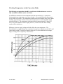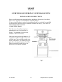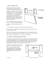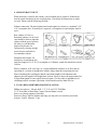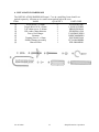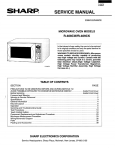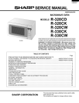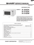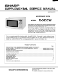
1
Servicing
Consumer
Microwave Ovens
Student Guide
Covers 1999 - 2000 models
ST-MWO2000
The microwave oven is made of three basic sections, the magnetron, the high
voltage, and the control section. The intent of this training manual is to explain how
each section operates and cover the troubleshooting techniques required for proper
repair of the Sharp microwave oven line for 1999 - 2000.
CONTENTS
Microwave Oven Basics
1
Microwave Emission Check
19
Microwave Measurement Procedure
20
Magnetron section
22
High Voltage section
27
Control section
30
Sensor circuits
37
Convection section
43
Protection circuits
48
Compu-cook, Compu-Defrost & Express defrost
50
OTR MWO Installation
51
General Service Hints
64
Commonly used parts for 2000 models
75
Commonly used parts for 1999 models
106
MICROWAVE OVEN BASICS
What Is Microwave Energy?
____________________________________________________
When a stone is thrown into a quiet pond, waves are formed which radiate outward from
the point at which the stone broke the water's surface. There are other kinds of waves that
we cannot see, but know they exist because we observe their effect. They are known
collectively under the term radiation, the process of emitting radiant energy in the form
of waves or particles.
These waves also radiate outward from the center like the waves on the surface of the
pond. They travel, however, at the speed of light, 186,282 miles per second, and carry
small bundles of energy called photons that vibrate at various frequencies.
There are two basic kinds of electromagnetic radiation:
IONIZING
X-rays
gamma rays
cosmic rays
ultra-violet rays
NON-IONIZING
radio waves
microwaves
infra-red waves
light waves
IONIZING RADIATION can cause chemical changes to take place with little or no
temperature rise.
NON-IONIZING radiation in sufficient intensity will cause a rise in temperature.
Ver SG 9/200
1
Sharp Electronics Corporation
Ver SG 9/200
2
Sharp Electronics Corporation
Radiant waves are characterized by their wavelength and their frequency of vibration
(number of complete cycles per second)
[Cycle is the change of an alternating waveform from zero to the most positive peak,
back to zero, to the most negative peak and back to zero.]
Wavelength x frequency / the speed of light frequency
1 cycle per second = 1 Hertz
1,000 cycles per second = 1 Kilohertz
1,000,000 cycles per second = 1 Megahertz
Thus as the frequency increases the wavelength becomes shorter.
Microwaves vibrate millions of times per second (that is, they have a very high
frequency) and are, therefore, very short waves, hence the term microwaves.
There are two microwave frequencies in general use for microwave ovens:
• 915 MHz (wavelength is 32 cm or about 12.5”)
• 2450 MHz (wavelength is 12 cm or about 5”)
These are two of the frequencies allocated by the Federal Communications Commission
(FCC) for Industrial, Scientific and Medical Use (sometimes called the ISM frequencies).
The term MHz stands for megahertz and means millions of cycles per second. The term
hertz is used to honor Heinrich Hertz, a German physicist who succeeded in producing
and detecting electromagnetic waves, which were later called Hertzian waves.
Ver SG 9/200
3
Sharp Electronics Corporation
In summary, microwave energy consists of bundles of energy vibrating at microwave
frequencies and moving at the speed of light. The effect on material in which they are
absorbed is a rise in temperature.
CLASSIFICATION OF ELECTROMAGNETIC WAVES
BAND
FREQUENCY
Very
Low
Frequency
VLF
LF
WAVELENGTH
100 Km
10 KHz
10 Km
Low
Frequency
100 KHz
MF
Medium
Frequency
1 MHz
100 m
HF
High Frequency
10 MHz
10 m
100 MHz
1m
1 GHz
10 cm
Very
High
Frequency
Ultra
High
Frequency
Super
High
Frequency
Extreme
High
Frequency
VHF
UHF
SHF
EHF
1 Km
(Microwave Oven)
10 GHz
1 cm
100 GHz
1 mm
10 -3 mm
INFRARED
106 GHz
10 -6 mm
VISIBLE
ULTRA
VIOLET
X-RAY
GAMMARAY
Electromagnetic Wave:
Microwave:
Wavelength:
Wavelength for Microwave Oven:
Ver SG 9/200
4
10 KHz - - - 300 GHz
300 MHz - - - 300 GHz
λ= c/f NOTE: c = 3 x 10⁸
λ= 12.24 cm Note: f = 2450 MHz
Sharp Electronics Corporation
Microwave energy looses power as it travels through space.
Power is lost at a rate that is inversely proportional to
the distance traveled.
____________________________________________________
Microwave Properties
____________________________________________________
So far we have mentioned two characteristics or properties of microwave energy:
absorption and transmission. Like light waves, microwave energy is also reflected.
Metals reflect microwaves and since there is no absorption, metals do no heat. Many
materials in addition to glass transmit microwaves and again since there is no absorption
there is no heating. Paper, china and some plastics transmit microwaves and are therefore
likely candidate materials for utensils for use in microwave ovens. The overall result is
that we are able to cook or heat foods in an oven on utensils, which are relatively cool to
the touch. No more burnt fingers.
Reflection
Microwave energy is reflected
from metals. Metals do not
heat.
Transmission
Many materials transmit
microwave and do not
heat
Ver SG 9/200
5
Sharp Electronics Corporation
Absorption
Those materials which absorb
microwaves, are heated. Foods
rank high as microwave
absorbers.
____________________________________________________
Advantages of Microwave Oven Heating
____________________________________________________
As the conventional heating methods apply heat to the exterior of a substance; dielectric
substances such as foods, wood, plastics, and rubber are heated unevenly because they
are poor in heat transfer and slow in heat penetration, resulting in a considerable
differential temperature between the exterior and the interior. Accordingly, the heating
temperature needs to be increased gradually in a long time if uniform heating is required.
Also, much heat is wasted for other substances than the heating object, for example, air,
pots, pans and the heat source. Thus the conventional heating is poor in the heat
efficiency and also difficult in the adjustment of the heating rate. On the contrary,
microwave oven heating has the following advantages.
1. Even Heating: Since the microwave penetrates into substances to some depth,
it heats the substances more evenly than the conventional heating methods.
2. Very high heating efficiency and speedy cooking.
3. The microwaves do not heat anything other than absorbing materials such as
food.
4. Exact Control of Heating Rate: The microwave output is regulated as desired
and the cooking time can be instantaneously set by a timer.
5. Heating Substance of any Shape: The microwave can easily penetrate and
scatter into the heating substance of any shape.
6. Simple oven construction and easy handling. The controls are very few and
they are solid state.
7. Very clean heating system, suitable for foods and pharmacy.
Ver SG 9/200
6
Sharp Electronics Corporation
____________________________________________________
How Does Microwave Energy Produce Heat?
____________________________________________________
All matter is made up of atoms and molecules. Some of these molecules are electrically
neutral, that is they have no electrical charge. Carbon tetrachloride, benzene and paraffin
wax are examples of electrically neutral materials and microwave energy will pass
through these compounds as if they weren’t present.
Most matter, however, is not electrically neutral, and when an electrical field is applied
the molecules tend to behave like microscopic magnets and attempt to line up with the
field. However, when the electric field is changing millions of times each second, these
molecular magnets are unable to keep up because of other forces acting to slow them
down, known as friction. Such forces which restrict their movement may be mechanical
such as is the case with ice or solid fats, or viscous as the case with a syrup like molasses.
The energy of the microwaves in trying to overcome these forces is converted to heat. In
a sense the material converts the energy to heat, or it might be said that the material heats
itself.
Ver SG 9/200
7
Sharp Electronics Corporation
We physically experience a similar phenomenon when we stand inside before a window
on a cold sunny day. The sun generates energy that is radiated through space to the earth.
The rays, mostly infrared, pass though the glass window without heating it. The glass is
transparent to them. The window itself is cold to the touch. The molecules of our body,
being electrically charged, behave like tiny magnets and convert the sun’s energy to heat,
and our body feels warm.
____________________________________________________
How Does Microwave Energy Cook So Fast?
________________________________________________
An additional characteristic of microwave energy is its ability to penetrate deeply into
food materials and to produce heat instantaneously as it penetrates. This is in sharp
contrast to conventional heating, which depends on the conduction of heat from the
surface to the inside. Conduction heating can be accelerated only by increasing the
surface temperature and obviously there are limits to this approach if excessive
overcooking of the surface of the food is to be avoided.
Measurement of the temperature distribution in an item heated in a microwave oven
reveals another difference. The surface will be usually cooler than an inch or so below
the surface. This is caused by radiation of heat from the food surface to the cooler
surroundings of the microwave oven. It does not happen in a conventional oven because
of the much higher temperatures in such an oven.
Ver SG 9/200
8
Sharp Electronics Corporation
____________________________________________________
Microwave Power: Its Measurement and Its Meaning
____________________________________________________
To properly develop a sense of timing in microwave cooking, it is first necessary to know
how much power is available in the oven. A microwave oven is not like a conventional
hot oven. There is no excess of heat available. All of the microwave energy is absorbed
by the food. There is little or no wasted energy.
We measure power by converting the microwave energy into heat and measuring it in a
simple calorimeter. The tools we need are a Pyrex measuring cup, a thermometer, a
clock and some cold water.
Pour two cups of cold tap water in
the Pyrex measuring cup. Note the
temperature. Heat the water in the
microwave oven for one minute and
measure the temperature again. The
difference in temperature times 17.5
is the power in watts. This is the
amount of power generated in the
oven in one hour.
One-sixtieth
th
(1/60 ) of this power is available
every minute.
If the oven power is 1000 watts (1
kilowatt), then there are 3413 British
Thermal Units of heat available with
which to cook.
A British Thermal Unit (Btu) is the amount of heat which will raise the temperature of
one pound of water one degree Fahrenheit. In terms of BTU then, a one kilowatt oven
puts out 57 Btu each minute, and if one pound of water were placed in the oven it should
increase in temperature 57°F. in one minute.
With this information the effect of food composition on heating time can be discussed
somewhat more intelligently. Most foods contain moisture in varying amounts with the
exception of pure fats like salad oils, shortening and lard. Another exception is
dehydrated foods which do not depend on moisture to convert microwave energy into
heat. The amount of moisture in a food has a direct bearing on its heating rate in a
microwave oven.
Ver SG 9/200
9
Sharp Electronics Corporation
One pound of food with 50% moisture will take less time to heat to a specific temperature
than one pound of food with 75% moisture. Or if both are heated for the same length of
time, the former will reach a higher temperature than the latter. One pound of water,
however, will heat only half as fast as one pound of fat. The reason for this requires an
explanation of the term specific heat. This is a measure of a material’s ability to hold
heat as compared to water. Water has a value of one (1.0). Fats are about 0.5. Thus
water takes twice as much heat as fat to increase its temperature by one degree.
Therefore in our one kilowatt oven, one pound of fat will increase in temperature by
114°F, however, the same amount of water will only increase 57°F. (It should be noted
that this does not apply at high temperatures where some of the water may be changed to
steam. This change uses up much more energy.)
A simple formula shows the relationship between the heat required and these other
factors:
“Heat required (BTU) equals Weight (lbs.) times specific heat times
temperature difference (°F.)”
Q=W x s x t
Here’s an example:
How long would it take to heat 12 ounces of canned green beans to 160°F. in a one
kilowatt microwave oven? The specific heat of most vegetables because of their high
moisture content is around 0.9. Let us assume that the beans would be at an initial
temperature of about 70°F.
Q = 0.75? lbs. x 0.9 x (160°F. - 70°F.)
Q = 60.75 BTU
Since our oven (1 kW) provided 57 BTU per minute, then the heat required (Q) divided
by 57 BTU/minute would give the time.
60.75/57.0 = about 1 minute 3 seconds
How long would it take if the green beans were just removed from a 40°F. refrigerator?
Q = 0.75 lbs. X 0.9 x (160°F. - 40°F.)
Q = 81
Time = 81/57 = about 1.5 minutes
When two foods at different starting temperatures are heated simultaneously in a
microwave oven the colder food takes longer than the warmer food. An interesting
example is that of apple pie and ice cream. With the pie at room temperature and a scoop
of hard frozen ice cream on top, the pie can be warmed without melting the ice cream.
About 15 seconds in a 1 kW oven will do the trick.
Ver SG 9/200
10
Sharp Electronics Corporation
____________________________________________________
Browning
____________________________________________________
The brown surface color of foods is due to a chemical reaction between food sugars and
amino acids, the building blocks of protein foods. This reaction proceeds slowly at low
temperatures and is accelerated by increasing the temperature. In microwave cooking the
surface temperature of foods rarely exceeds 212°F, the boiling point of water, and is
usually much lower. Because of this, most foods cooked in microwave ovens lack the
surface coloration expected of certain foods. A steak or a meat patty, for example, would
have a gray unappetizing surface appearance. Baked goods would not have a brown
crust. The appearance of such foods can be enhanced by placing them in a hot oven for a
few minutes, or in the case of the steak and meat patty, on a grill or under a broiler. A
number of restaurants which do a sizable steak business pre-sear a quantity of steaks in
advance and finish them in seconds in the microwave when ordered. Some foods, which
because of their size take longer to cook in a microwave oven, do take on an acceptable
surface appearance. The presence of surface fats as in beef roasts or roasting chickens
and turkeys aid this. These fats reach temperatures above 212°F. and act to accelerate the
browning reaction.
____________________________________________________
Size Grading
____________________________________________________
Since small items cook faster than large items, it is good practice to do all of one size at a
time. In baking potatoes, for example, if they are nearly alike in size they will all be
finished at the same time. The alternative to size grading is to remove the smaller items
as they are done and continue to cook the larger items. This requires considerably more
attention.
Ver SG 9/200
11
Sharp Electronics Corporation
____________________________________________________
Food Geometry
____________________________________________________
Regular shapes heat more uniformly in a microwave oven. When the shape is irregular
the thin, narrow parts tend to overcook and may be dried out by the time the thicker parts
are done. This of course happens in conventional cooking but is less pronounced because
cooking is slower. Where it is possible to control the shape, as for example with a meat
loaf or by tying a beef roast into a more cylindrical form, much more uniform results are
obtained. Where this is not possible, thin parts may be covered with aluminum foil for a
part of the cooking cycle. The same technique can be applied in protecting the wing tips
and legs of roasting chickens and turkeys.
____________________________________________________
Shielding
____________________________________________________
This subject was mentioned briefly before, but deserves a more lengthy treatment. Since
metals reflect microwave energy we can use this phenomenon to advantage in certain
cooking operations to restrict heating in certain areas. A good example to illustrate this
effect is in the cooking of a large
beef roast. First, wrap aluminum
foil over the outer two inches at
each end of the roast and cook for
2 to 3 minutes per pound ( in a 1
kW oven 20 to 30 minutes for a 10
lb. Roast). The roast should be
turned at least once during this
time. Remove the foil and cook for
an equal period of time, again
turning at least once. Remove the
roast from the microwave oven, cover and let stand an additional 30 to 45 minutes or
until a meat thermometer inserted into the center of the roast reads 140-150?F. Shielding
the roast in this way during cooking will insure a more uniform degree of doneness from
one end of the roast to the other. If a more will done roast is desired, it can be returned to
the oven for an additional 5 to 10 minutes.
Ver SG 9/200
12
Sharp Electronics Corporation
A circle of foil placed in the center of a
slice of left over roast will keep it from
becoming too well done while warming it
for consumption.
When heating a
casserole, the use of a strip of foil around
the edge will slow down the heating
effect in this area and insure a hotter
center.
There are many possibilities using foil
and metal forms to control microwave
heating. Only a few suggestions have
been noted here.
____________________________________________________
Containers and Packaging Materials
____________________________________________________
One of the principle advantages of microwave cooking is that it often can be
accomplished in the serving dish or in the package in which the food was purchased.
With the exception of metals, all packaging materials are transparent to microwave
energy. The list includes ovenproof glass, ceramics, chinaware, plastic ware, and paper
containers of all types and plastic films.
It is not entirely true that in microwave cooking only the food is heated. Some plastics
must be used with caution. Melamine plastic ware, for example, absorbs enough energy
to cause charring in places. Such plastic ware quickly becomes too hot to handle.
Styrene's give off a strong odor and deform if heated too long.
The amount of energy containers absorb can be determined by making an oven power
measurement with and without the container in the oven. The difference is the amount of
energy absorbed by the container.
Some ceramic dinnerware may absorb several watts of power for each ounce of weight.
Considering the weight of such containers, the total power absorbed can be considerable.
In some cases this is a desirable feature since foods in these dishes tend to remain warm
longer after serving.
Certain plastic materials such as high density polyethylene and polypropylene make quite
acceptable containers for microwave oven use. Some foods are being packaged
commercially in containers made of these materials. A number of plastic containers are
being offered which can be used in both microwave and conventional ovens.
Ver SG 9/200
13
Sharp Electronics Corporation
The Microwave Oven
____________________________________________________
Unlike most cooking appliances in which the food to be cooked is overwhelmed with
heat, a microwave oven operates essentially at room temperature. In fact, if anything, the
food heats the oven.
Meet the key components of a microwave oven:
1.
2.
3.
4.
5.
Cavity
Door
Magnetron
Waveguide
Stirrer Antenna
6. Power Supply
7. Power Cord
Provides frame for microwave oven.
Provides access to cavity.
Generation of microwave power.
Couples magnetron antenna to oven cavity.
Reflects microwave energy to ensure even
cooking.
Supply filament and high voltage to
magnetron.
Connects to electrical outlet.
The main function of the power supply is to convert AC line voltage to the high voltages
required by the microwave energy generator, the magnetron. When the magnetron is
energized it generates high frequency energy which then passes down the waveguide to
the cavity. As the stirrer antenna turns, it provides even absorption in the food load.
Without the stirrer antenna, the food load would be subject to standing hot and cold spots
where the microwaves are not evenly distributed.
The food load is supported on a ceramic shelf positioned off the floor of the oven for a
reason. This position permits some of the energy to be reflected from the oven floor into
the food from below. If this were not done the bottom of the food would lag behind in
cooking giving uneven doneness.
Ver SG 9/200
14
Sharp Electronics Corporation
The purpose of the oven door is to provide an access to the cavity and also to confine the
microwave energy. A proper fitting door is essential to completely confine the energy
and, it, as well as the door flange, should be wiped clean regularly to insure good contact
of the door and the door flange. Considerable ingenuity has gone into microwave oven
door design because it is such a critical feature of the oven. A quarter wave slot or
“choke” seal around the perimeter of the door acts to choke off or cancel out microwave
emissions at this point.
Oven controls consist mainly of a touch pad, microcomputer, function display, interlock
switches and primary (cook) relay. The microcomputer is very accurate so that heating
cycles can be set with a high degree of accuracy. The microcomputer is important
because all microwave cooking is gauged by time, not temperature and time.
A few extra seconds of cook time in some cases can mean the difference between success
and failure. An audio signal usually indicates when the set time has elapsed and the oven
has turned itself off. The oven may also be turned off simply opening the door. To
protect the user from unnecessary exposure to microwave energy is a requirement of all
microwave ovens, and any one of the three interlocks operate when the door is opened,
which could turn off the oven.
The Heart of a Microwave Oven
Magnetron & associated parts:
1. Temperature fuse to protect the magnetron against excessive heat.
2. Fan motor to force cool air in the magnetron
3. Fan duct to direct air stream from the motor.
The magnetron cross-section shows a common twelve-cavity design. Each cavity is
resonant at the fundamental frequency of oscillation. As the cathode is heated in a hard
vacuum, electrons are “boiled off” accelerated towards the anode by a high voltage
(typically -4000 volts) and rotated in a helical path by the magnetic focusing field. As
electrons boil off, they rotate in clouds, tangential to the cavities, stimulating the build-up
of microwave energy in these cavities. As the rotating electrons interact with the fields in
the cavities, they get more strongly focused until “spokes” of electrons are formed, much
like the spokes of a rotating wheel. When the spokes of electrons, or space charge, rotate
synchronously with the microwave fields of the cavities, the maximum energy is coupled
from the electrons to the oscillations. Straps connect alternate cavities so that all cavities
resonate in unison, energy flows up the antenna, and is fed into the cooking cavity.
Ver SG 9/200
15
Sharp Electronics Corporation
Power Transformer:
The filament transformer is of conventional design and supplies 3V to the filament of the
magnetron. The high voltage transformer is a unique design and is called a leakage
transformer.
In normal operation, the magnetic flux is induced in the path labeled A (below). When
excessive current is drawn the magnetic flux is induce in the path labeled B. This way,
any short in the secondary will automatically disable the high voltage section and protect
expensive parts against damage.
Ver SG 9/200
16
Sharp Electronics Corporation
____________________________________________________
Microwave Safety
____________________________________________________
Public Law 90-602, the Radiation Control for Health and Safety Act of 1968 was passed
by Congress, October 18, 1968. One of the purposes of this law was to establish
standards for various electronic products’ radiation so that the public could not be
exposed unnecessarily to excessive amounts of radiation of various kinds given off by
these products. Items such as television sets, sun lamps, microwave ovens and various
other products are covered by this law. Standards for microwave ovens went into effect
October 6, 1971. Under these standards, radiation leakage from microwave ovens cannot
exceed one (1) milliwatt per square centimeter (mW/cm2) measured two (2) inches from
the oven prior to factory release, and five (5) mW/cm2 thereafter. The measuring
equipment to be used is also specified in the standards.
Before the standard for microwave ovens went into effect, industry had operated with a
voluntary standard 10mW/cm2. Standards were established in order to protect
technicians working around radar sites from being exposed to possibly dangerous levels
of microwave radiation. Experiments with animals had shown that continuous exposure
at relatively high levels of radiation could raise body temperature to a fatal level. The
10mW/cm2 standard had a considerable margin of safety built in. This standard for radar
workers was based on what is called “whole body” radiation: that is, conditions under
which each square centimeter of the body is exposed to radiation. It is said that body
temperature will rise 1°F. if exposed long enough at this power level. By way of
contrast, solar energy reaching the Earth on a sunny day may be 60 to 100 mW/cm2.
Staring at the sun represents a far greater hazard than exposure to 10 mW/cm2 of
microwave radiation. Serious eye damage, even blindness has been known to occur from
improper observation of a solar eclipse. On the other hand, microwave diathermy at the
same frequency used in microwave ovens is used for treatment of certain eye diseases.
The level of energy employed is much greater than 10mW/cm2 and for periods longer
than one would stand in front of a microwave oven. Dr. James Ban Allen, a well known
authority of radiation technology has expressed the microwave hazard from the operation
of a microwave oven, as “about the same as the likelihood of getting a skin tan from
moonlight.” Even the Surgeon General of the United States has publicly stated that no
injuries from microwave oven use have been reported.
Ver SG 9/200
17
Sharp Electronics Corporation
The main concern is about microwave radiation leakage from around the oven door.
Some doors of earlier models were relatively loose fitting, particularly after being in use
for a while. Microwave energy can radiate from around such a door, just like light can be
seen under a door to a lighted room. The difference is that microwave radiation isn’t
visible. It presence, however, can be detected with the
proper instruments. A neon lamp (not connected to
any electrical source) will light up when held close to
a leaky microwave oven door. Other instrument must
be used to measure the exact level of radiation. When
carrying out these checks be sure to have at least a cup
of cold water in the oven. Check to also to see if the
door flange and faceplate are free of food spatters.
Spills and spatters can build up in these areas and
affect the door seal enough to cause leakage. Keeping
the oven clean might eliminate the need for a service
call.
Another important point to remember is that radiation diminishes by the square of the
distance from the source. Leakage of microwave energy from a microwave oven follows
this formula too. An oven radiating 10mW/ cm2 measured two inches from the door will
show a reading at 20 inches, about an arms length, of 0.1 mW/cm2. Using the same
formula, if the measurement at the door is 100 mW/cm2, the level at 20 inches will be
only 1 mW/cm 2. When one considers that microwave diathermy treatment of the eye is
carried out at levels of over 100 mW/cm2 with the eye positioned a bare three inches from
the device, it is readily apparent that there is little need for concern about hazards of
microwave oven use.
Ver SG 9/200
18
Sharp Electronics Corporation
MICROWAVE OVEN EMISSION CHECK
Before servicing an operative unit, perform a microwave emission check per the
Microwave Measurement Procedure on page 24 of this manual.
If the microwave emissions level is in excess of the specified limit:
1. Instruct the owner not to use the unit, and
2. Immediately contact SHARP ELECTRONICS CORPORATION @ 1-800-237-4277
Should the unit operate with the door open:
1. Instruct the owner not to operate the unit, and
2. Immediately contact SHARP ELECTRONICS CORPORATION and The Food and
Drug Administration’s Center for Radiological Devices and Radiological health.
Service personnel should inform SHARP ELECTRONICS CORPORATION of any
certified unit found with emissions in excess of 4mW/cm2. The owner of the unit should
be instructed not to use the unit until the oven has been brought into compliance.
Ver SG 9/200
19
Sharp Electronics Corporation
MICROWAVE MEASUREMENT PROCEDURE
A. Requirements
1) Microwave leakage limit (power density limit):
The power density of microwave radiation emitted by a microwave oven should
not exceed 1mW/cm2 at any point 5cm or more from the external surface of the
oven, measured prior to the acquisition by a purchaser, and thereafter (through
the useful life of the oven), 5mW/cm2 at any point 5cm or more from the
external surface of the oven.
2) Safety Interlock Switches, Primary interlock relay and door sensing switch
shall prevent microwave radiation emission in excess of the requirement as
above mentioned, secondary interlock switch shall prevent microwave radiation
emission in excess of 5mW/cm2 at any point 5cm or more from the external
surface of the oven.
B. Preparation for testing:
Before beginning the actual measurement of leakage, proceed as follows:
1) Make sure that the actual instrument is operating normally as specified in its
instruction booklet.
Important:
Survey instruments that comply with the requirement for instrumentation
as prescribed by the performance standard for microwave ovens, 21 CFR
1030. 10(c)(3)(i), must be used for testing
2) Place the oven tray in the oven cavity.
3) Place the load of 275 + or - 15 ml (9.8 oz) of tap water initially at 20 + or (68 degrees F) in the center of the oven cavity. The water container shall be a
low form of 600 ml (20 oz) beaker with an inside diameter of approx. 8.5 cm (3
1/2 in.) and made of an electrically nonconductive material such as glass or
plastic. The placing of this standard load in the oven is important not only to
protect the oven, but also to insure that any leakage is measured accurately.
4) Set the cooking control on Full Power Cooking Mode.
Ver SG 9/200
20
Sharp Electronics Corporation
5) Close the door and select a cook cycle of several minutes. If water begins to
boil before the survey is completed, replace it with 275 ml of cool water.
C. Leakage Test
Closed -door leakage test (microwave measurement)
1) Grasp the probe of the survey instrument and hold it perpendicular to the gap
between the door and the body of the oven.
2) Move the probe slowly, not faster than 1 in/sec (2.5 cm/sec) along the gap,
watching for the maximum indication on the meter.
3) Check for leakage at the door screen, sheet metal seams and other accessible
positions where the continuity of the metal has been breached (eg. around the
switches, indicator, and vents).
While testing for leakage around the door, pull the door away from the front
of the oven as far as is permitted by the closed latch assembly.
4) Measure carefully at the point of highest leakage and make sure the highest
leakage is no greater than 4mW/cm2 (to allow for meter uncertainty), and that
the secondary interlock switch does turn the oven OFF before any door
movement.
NOTE: After servicing, record data on the service invoice and microwave leakage report.
Ver SG 9/200
21
Sharp Electronics Corporation
MAGNETRON SECTION
In order for the service technician to comprehend the service procedures, and their
limitations, they must have a understanding of the operation of the magnetron tube.
Refer to the next page for the following explanation.
The magnetron is made of a cathode, an anode, and an antenna.
The cathode is made of a substance which will have many free electrons in its molecular
structure. Usually this substance is a man made element which combines barium and
strontium oxide together. Most manufacturers just refer to the oxide coating on the
cathode as “rare earth”. The cathode is then encircled with an anode which is constructed
to create resonate cavities within its interior. The resonate cavities are then connected to
an antenna. The next requirement for manufacturing is to evacuate the air space between
the cathode and anode creating a perfect vacuum. A heater is then placed on the cathode
which shares one of its terminals with the high voltage lead. Magnets are then placed
around the outer side of the anode. The magnetron tube is now ready for operation.
The first requirement for the tube to function requires us to get the free electrons of the
rare earth element off the cathode, suspending them in the vacuum around the cathode.
This is accomplished by pushing current through the heater which is on the cathode. The
current is pushed by a relatively small alternating voltage, usually around 3 volts AC. As
the cathode heats the electrons begin moving. Much like water is in solid state (ice)
when cold, as heat is applied the molecules will begin movement until they actually leave
the mass in the form of steam. We usually refer to the process of electron movement
from the cathode to the vacuum area as the boiling off process although the electrons do
not experience the change of state which we often relate to when we think of boiling.
The next requirement is to get the electron mass to move away from the cathode with a
certain degree of velocity. This is accomplished by putting a high voltage charge on the
cathode. The charge is usually about 4000 volts negative, direct current. The anode is
then connected directly to ground. The movement of electrons is from negative to
positive, the large negative charged electrons see ground as positive which will cause
them to accelerate outward toward the anode.
The next step for the tube to operate is the magnetic flux generated from the permanent
magnets on the magnetron, which will restrict the electron movement. The electrons can
not strike the anode directly, they must move past the resonate cavities of the anode. As
the cloud of electrons pass a cavity they will create movement of the electrons within the
anode material (usually a copper alloy).
Ver SG 9/200
22
Sharp Electronics Corporation
Ver SG 9/200
23
Sharp Electronics Corporation
The resonate cavities are so designed that the movement of electrons will be only allowed
at the frequency of 2450 MHz. The positive and negative fields created as the cloud
passes one cavity to another will create the pushing and pulling of the electrons all the
way to the antenna. As the antenna gets moving within, it will generate electro-magnetic
energy, at the frequency of 2450 MHz. This is the RF energy that is used by microwave
ovens.
A symptom of a failed magnetron is a no heat complaint. After confirming the power
supply has not failed, unplug the unit and remove the wires from the terminals of the
magnetron. With an ohmmeter check the resistance of the heater on the cathode. The
reading should be about .25 Ohms. If the resistance is infinite the heater is open. This of
course would not allow the electrons to boil off the cathode surface. Without the cloud of
electrons in the vacuum area the tube can not generate energy within the resonate
cavities. The magnetron would have to be replaced to correct the problem.
Next, with an ohmmeter check from the magnetron terminals to the case of the
magnetron. An infinite reading would indicate the tube does not have a cathode to anode
short. If a short existed between the cathode to anode the electrons would go directly to
ground, taking the path of least resistance. This of course would again mean the cloud of
electrons needed within the tube was not present and the tube would not generate energy.
Any resistance reading at this point would warrant replacement of the magnetron.
The last test that can be taken on the magnetron is a visual check. Check the magnetic
rings that are around the anode for a break. If the magnets are broken they will prevent
the spherical movement of electrons in the vacuum area of the tube. All the electrons
will align themselves up to a North Pole that was developed at the break. Again without
the movement of the clouds of electrons past the resonate cavities, the tube will not
generate energy. The magnetron tube would have to be replaced.
Some failures within the magnetron can not be detected with the use of meters or visual
inspections. These types of failures must be diagnosed via process of elimination. Check
all other possible causes for the tube not to operate, if no other reason is detected, replace
the magnetron. An example of this type of failure would be a gassy tube. This condition
occurs when the vacuum is lost within the tube. The introduction of various gasses will
cause friction due to the electrons hitting the electrons from the alien gasses. The heat
generated from these collisions will super heat the cathode causing deterioration of the
cathode. The tube will first emit too much power and the customer will complain of food
over cooking. Then it will very quickly reverse symptoms and have low or no output.
This condition of extra heat is usually the reason why the magnets will crack.
Ver SG 9/200
24
Sharp Electronics Corporation
Another failure that can not be easily detected is the weak magnetron. After years of
operation the amount of electrons that the cathode can release is reduced. The charge that
is carried in the cloud of electrons is diminished and the amount of energy transferred to
the resonate cavities is also reduced. This failure can not be avoided and is in proportion
to the amount of time the oven is used. To detect a weak magnetron a running wattage
test must be taken.
During the 1990 product year the microwave industry standardized the rating
specifications for output power. The ovens prior to 1990 used the 2-liter water load
rating standard . Ovens during 1990 used both the 2-liter method and the new IEC-705
test procedure. When you troubleshoot an oven and suspect the magnetron has low
output make sure you check the method used to initially rate the oven. If you use the 2liter method on an oven which was initially rated by the IEC-705 method the output will
be drastically lower. This of course would cause you to replace the magnetron and
incorrectly diagnose the trouble.
Due to the complex formula and the precision required to successfully check the output,
we recommend you use the following guidelines for testing a suspected weak magnetron.
Power output of the magnetron can be determined by performing a water temperature rise
test. This test should only be used if the circuits check good in all the prior ohmmeter
tests. This test requires a 16-ounce cup and an accurate mercury thermometer. For
accurate results, the following procedure must be followed carefully:
1. Fill the measuring cup with 16 ounces of tap water and measure the temperature of
the water with the thermometer. Stir the thermometer through the water until the
temperature stabilizes. Record the temperature of the water.
2. Place the cup of water in the oven, selecting more than 60 seconds of cooking time.
Allow the water to heat for 60 seconds, measuring the time with a stopwatch, second
hand, or digital read out countdown.
3. Remove the cup from the oven and again measure the temperature, making sure to
stir the thermometer through the water until maximum temperature is reached.
4. Subtract the cold water temperature from the hot water temperature. The normal
result should be:
15-28 degrees Fahrenheit if testing a 600 watt oven
18-33 degrees Fahrenheit if testing a 700 watt oven
21-39 degrees Fahrenheit if testing a 850 watt oven
22-43 degrees Fahrenheit if testing a 900 watt oven
27.7-51.5 degrees Fahrenheit if testing a 950 watt oven
34.7-64.6 degrees Fahrenheit if testing a 1000 watt oven
32.6-64.6 degrees Fahrenheit if testing a 1100 watt oven
Ver SG 9/200
25
Sharp Electronics Corporation
If the water temperatures are accurately measured and tested for the required time period,
the tests results will indicate if the magnetron tube has low power output (low rise in
water temperature), which would extend the cooking time, or a high power output (high
rise in water temperature), which would decrease the cooking time. Because cooking
time can be adjusted to compensate for power output, the magnetron tube should not be
replaced unless the water temperature rise test indicates a power output well above or
below the normal limits.
Test results are only accurate if the power supply line voltage is 120 volts and the oven
cavity is clean.
Ver SG 9/200
26
Sharp Electronics Corporation
HIGH VOLTAGE SECTION
The high voltage section of the microwave oven is the section responsible for developing
the voltages required by the magnetron. These voltages are the 3 volts AC and the -4000
volts DC. Refer to the graphic on page 29 for the following explanation.
The voltage induction principle of a transformer is used to develop the volts from the 120
volt supply. The 3 volts AC is developed on the voltage step down winding which steps
the voltage down by a 40 to 1 ratio. For every 40 volts applied to the primary winding
we will get 1 volt on the secondary of the step down winding. This winding is often
referred to as the filament winding. Due to the induction principle the output of the
transformer must be alternating voltage (AC). This voltage is applied directly across the
heating element that heats the cathode surface of the magnetron.
The -4000 volts required to charge the electrons within the magnetron’s vacuum space is
developed on the step up winding. This winding steps the voltage up on a ratio of 1 to
20. For every 1 volt applied to the primary winding, 20 volts will be developed on the
secondary. On a unit that has 120 volts applied to the primary the output on the high
voltage winding will be about 2400 volts AC. This voltage must now be rectified
(converted into DC voltage) and increased. This is accomplished with the use of a silicon
rectifier and a capacitor. As the transformer makes its positive and negative swings along
the sine wave, the rectifier will conduct only during the negative swing. During this
period of time the rectifier will totally shunt the magnetron and charge the capacitor.
During the positive swing the rectifier will not conduct. This will now give us the 2400
volt potential within the secondary winding along with the 2400 volts stored in the
capacitor. The voltage is in series aiding which gives the 4800 volt potential available for
the magnetron.
The voltages referred to in our explanation are not real voltages that you would measure
on a working microwave. In practice the voltages may be lower and will vary from
model to model. The transformer secondary windings are matched to an output rating of
the magnetron. The size of the capacitor is also matched to the magnetron and
transformer output. The rectifier is current rated for the individual circuit it is used in.
Never replace a rectifier, capacitor, transformer, or magnetron with a generic part. You
can compromise the circuit operation and reliability of the unit.
If you suspect a problem in the magnetron power supply the following test procedure
should be used.
Disconnect the 120 volt power source from the oven (unplug the unit). Discharge the
capacitor. A capacitor is nothing more than a storage device for electricity. Even with
the power disconnected the capacitor can hold a charge of around 2000 volts. This
voltage must be discharged to render the unit safe to work on. To discharge the
capacitor, short across the terminals. An arc may occur when the terminals are shorted.
This would be a normal situation.
Ver SG 9/200
27
Sharp Electronics Corporation
With an ohmmeter, check the resistance of the primary winding. A normal reading
would be less than one ohm. This reading is hard to detect on an analog meter as the
needle appears to indicate a short. However, if the reading looks close to the shorted
condition and the line fuse is not blown the winding is probably good. Of course, any
time resistance checks are being taken, the component should be isolated (wires removed
from terminals). This prevents the possibility of putting other resistance’s in parallel with
the component. giving false readings. The secondary is also checked with an ohmmeter.
The filament winding should indicate less than one ohm. The high voltage winding
should indicate anywhere from 50 to 200 ohms depending on the output rating of the
model oven you are checking. Be certain to refer to the service manual for the exact ohm
reading on the high voltage secondary as layer shorts are the most common problem with
power transformers (the winding reads 90 ohms on your meter but the service manual
states the reading should be 120 ohms, this is a layer short).
The rectifier is also checked with an ohmmeter. Set the analog meter on the X 10,000
scale. Place the negative lead of the meter on the cathode of the rectifier (the cathode is
the side to which the arrowhead points toward). A reading of 50,000 ohms is normal. If
an infinite reading or a low resistance reading is indicated the rectifier is defective.
Reverse the leads of the ohmmeter on the rectifier terminals (the negative lead on the
anode). This should indicate an infinite reading on the meter, any other reading would
indicate a defective rectifier.
The capacitor is also checked with an ohmmeter. Isolate the capacitor and place the
meter leads on the leads of the capacitor. With the meter set on the X 10,000 scale, the
needle should swing towards a lower resistance reading. As the capacitor charges the
resistance should increase to an infinite reading. Reverse the meter leads and the same
deflection should occur as the capacitor now charges with the reverse polarity. If the
meter indicates a constant resistance the capacitor is shorted or leaky. If deflection is not
present it indicates the capacitor is open.
If the transformer, rectifier, and capacitor check good refer to the magnetron section of
this manual for test procedure.
Ver SG 9/200
28
Sharp Electronics Corporation
Ver SG 9/200
29
Sharp Electronics Corporation
CONTROL SECTION
The controls which are used in microwave ovens vary from oven to oven.
The mechanical timer control is used in models R-200BK, R-200BW, R-300BW and the
R-21HC. Refer to the wiring diagram section of this manual for the following
description.
The mechanical timer has two basic designs. The first is a simple motor and a single
switch. The timer dial, when turned, will cause the contacts of the timer switch to close.
As the switch contacts close they will complete the parallel circuit to the oven light, fan
motor, turn table motor, timer motor, and power transformer. Once the motor starts to
turn it will continue until it mechanically opens the timer switch contacts. This will open
the parallel circuit terminating all oven functions.
To diagnose the mechanical timer, unplug the unit, disconnect the power supply and
check continuity across the switch contacts. When the timer is in the off position an
infinite reading should be indicated on the meter. When the dial timer is turned to any on
position, zero ohms or continuity should be indicated. If the timer switch checks good,
restore power to the unit and turn the timer dial to close the switch contacts. With a volt
meter check for 120 volts across the motor terminals directly. A reading of 120 volts
should be indicated. If the voltage is present but the timer doesn’t operate, replace the
timer.
The second mechanical timer design has a second switch for the defrost function. The
switch is normally opened and closed by a cam that turns within the timer assembly. The
switch is located in series with the power transformer, therefore only affecting the
transformer operation as it opens and closes.
To diagnose the switch the oven must be operating. A voltage check across the defrost
switch must be taken. When the meter indicates 120 volts the switch is open. When the
meter indicates zero volts the switch is closed. If the meter fails to detect the switch
either opening or closing, replace the switch and/or the timer assembly depending on the
reason for the failure of the switch activation.
All other ovens utilize a solid state control. The control is an assembly which is
comprised of a key unit and a control unit. Refer to the Control Panel Circuit Operation
on the next page for the following explanation.
Ver SG 9/200
30
Sharp Electronics Corporation
Ver SG 9/200
31
Sharp Electronics Corporation
Control Panel Circuit
The key unit is a switching device. When a keypad is touched it will momentarily switch
an output signal from the microcontroller to the input ports of that same microcontroller.
The door sensing switch must be closed and working properly, as this switch is
responsible for enabling the input section of the microcontroller. The input command
will be recognized by the ROM section of the microcontroller and the desired command
will be executed.
To diagnose a failure in the key unit, disconnect the mylar ribbon connector between the
key unit and the control unit. With a small diameter solid wire, jump across the key
function which has the suspected failure. As an example, if an R-530BK will not clear
the display from the initial “flashing 8” condition, disconnect the ribbon connector and
insert the jumper wire on the control board connector at G1 and G12 (see page 33 for
layout of Key Unit for the R-530BK/BW). Of course the door must be closed and the
door sensing switch must be operating properly before this test can be made. If a beep is
heard and the display clears, the problem would be in the key unit. If the control does not
respond when the jumper connection is made the problem is in the control unit. Any pad
on the key unit can be tested in this same manner. However, keep in mind the
microcontroller is sequentially programmed. This means certain commands must be
entered ahead of others. As an example, the control must first be cleared, the clock set,
cooking time entered, and the start key touched. If we try to start the unit before time is
entered, the control will not respond.
To diagnose a failure in the control unit, place a voltmeter across the power input
terminals. Refer to the power unit circuit on page 34, model R-530BK. As an example,
if the display is dead and the control will not accept commands from the key unit proceed
as follows. Place a voltmeter across terminals A-1 and Common on the Power Unit
Circuit Board. 120 volts should be indicated on the meter. If zero volts is indicated, the
problem is in the circuitry ahead of the control assembly such as an open monitor fuse.
Do not condemn the control if this condition exists. If 120 volts is indicated across A-1
and Common further testing is required. With a voltmeter, check across the primary
windings of the low voltage transformer “T1”. The meter should indicate 120 volts. If
the voltage is present, the control is not accepting commands, and the display is dead,
replace the control assembly. If the meter indicates zero volts across the primary winding
of the transformer “T1” but 120 volts was indicated across A-1 and Common, check the
foil pattern between the two test points. When you locate the open foil proceed with the
repair procedure on page 35.
Control assemblies for microwave ovens are considered as a replaceable part once the
foil pattern repair is checked.
THIS PROCEDURE MUST BE FOLLOWED PRIOR TO CONDEMNING A
CONTROL ASSEMBLY ON ALL THE SOLID STATE CONTROLS FOR THIS
PRODUCT YEAR.
Ver SG 9/200
32
Sharp Electronics Corporation
G7
4
G6
3
G5
2
G4
1
G10
0
9
8
7
G11
Minute
Plus
Compu
Defrost
Fish /
seafood
Start
Touch
on
Clock
Frozen
snacks
G9
G8
5
G12
KEY UNIT FOR THE R-530BK/BW
Ver SG 9/200
Beverage
center
33
G3
G2
G1
Reheat
Popcorn
6
Baked
Potato
Fresh
vegetables
Custom
Help
Kitchen
Timer
Frozen
vegetables
Poultry
Ground
meat
Power
Level
Rice
Compu
Cook
Frozen main
dish
Stop
Clear
Sharp Electronics Corporation
Ver SG 9/200
34
Sharp Electronics Corporation
Procedure for repairing an open foil pattern
To protect the electronic circuits, microwave ovens are provided with a fine foil pattern
in the primary circuit that acts as a fuse. If the foil pattern is open, follow the
troubleshooting procedure as outlined below.
Problem: Power ON, Indicator does not light.
Step
Occurrence
1.
Only pattern “a” is
broken
2.
Patterns “a” and “b”
are broken
Cause or Correction
Insert jumper wire
J1 and solder.
(see page 37)
______________________________________________________
Insert coil
RCILF2003YAZZ
between “c” and “d”.
NOTE: At the time of this repair, make a visual inspection of the varistor for burn
damage, and test the transformer with an ohmmeter for the presence of a layer short.
Ver SG 9/200
35
Sharp Electronics Corporation
On models which have the liquid crystal display, be sure to check the flex connector
between the display and control board. The conductor strip on the board as well as the
flex connector must be clean. Any substance, such as grease or dirt, would cause
resistance to current flow between these parts and impede the operation of the display.
Clean this area with a residue free cleaning agent such as ethyl alcohol. Also inspect the
control for a crack or break in the area where the mounting screws hold the assembly into
the frame. If the contact between the board and flex connector is not tight the display
will not function or will function erratically.
The function of audible signal elimination, will allow the consumer to turn off the buzzer.
The Demonstration mode, will allow the consumer to run through a cooking sequence at
ten times the normal speed without turning on the power circuits. The Child lock, will
allow the consumer to disable their control panel to prevent unwanted oven operation
Refer to the “owners guide”, not the service manual, for the specific model you are
working on to determine what features the unit has and the correct procedure used to
activate and deactivate the feature.
Child Lock
The Child Lock prevents unwanted oven operation such as by small children.
The oven can be set so that the control panel is deactivated or locked.
Should a pad be touched, Lock On will appear in the display.
Audible Signal Elimination
Eliminates the audible signal when any of the pads are pressed.
Demonstration Mode
The consumer can use the demonstration mode to demonstrate different features without
power being applied to the high voltage section.
NOTE: Refer to the owners manual for the model you are working on for the correct
procedure to activate and deactivate the above feature.
Ver SG 9/200
36
Sharp Electronics Corporation
SENSOR CIRCUITS
Sensors used in microwave ovens are considered peripherals of the control assembly.
They are responsible for sending information back to the microcontroller, which in turn
sets the conditions for the microcontroller to turn power on or off to the select circuits.
The following is a list of sensors used.
Door Sensing and Secondary Interlock Switches:
The secondary interlock switch is mounted in the lower position of the latch hook and the
door sensing switch in the primary interlock system is mounted in the upper position of
the latch hook. They are activated by the latch heads on the door. When the door is
opened, the switches interrupt the power to all high voltage components. A cook cycle
cannot take place until the door is firmly closed thereby activating both interlock
switches. The primary interlock system consists of the door sensing switch and primary
interlock relay located on the control circuit board.
Thermal Cut-Out (Magnetron):
This thermal cut-out protects the magnetron against overheating. If the temperature goes
up higher than 257 degrees F (R-820BK/BW) because the fan motor is interrupted or the
ventilation openings are blocked, the thermal cut-out will open and line voltages to the
high voltage transformer will be cut off and the operation of the magnetron will be
stopped. The thermal cut-out will not resume.
Thermal Cut-Out (Oven):
The thermal cut-out located on the top of the oven cavity is designed to prevent damage
to the oven if the food in the oven catches fire due to over heating produced by improper
setting of the cooking time. Under the normal operation, the oven thermal cut-out
remains closed. However, when abnormally high temperatures are reached within the
oven cavity, the oven thermal cut-out will open at 338 degrees F (R-820BK/BW) causing
the oven to shut down. The thermal cut-out will close in at 311 degrees F (R820BK/BW).
Absolute humidity sensor (AH sensor):
This sensor detects humidity or steam generated from the food load. The microcontroller
monitors voltage across two thermistors. One thermistor is in a sealed chamber and the
other is open to air. This sensor is located in the rear exhaust vent and relies on the
venting system of the oven to blow air across it. As humidity builds up on the sensor in
the open air, it will begin to evaporate, which cools the thermistor. When a voltage
difference is developed across the two thermistors, the microcontroller will calculate the
remainder of the cooking time. Refer to pages 39-41 for proper test procedures.
Ver SG 9/200
37
Sharp Electronics Corporation
Oven temperature thermistor:
This sensor is used in ovens that have convection heat, The thermistor will change
resistance as the oven temperature increases. The microcontroller will compare the
voltage across the thermistor to the programmed voltage within the ROM. When the two
are equal, the convection heater will be turned off. Refer to page 42 for the proper test
procedure.
Damper switch:
This sensor monitors the position of the damper door on ovens that have the convection
cooking feature. The damper door must be closed for convection cooking and open for
the microwave mode. A signal is developed across the damper switch that is converted to
either a logic high (when the switch is open) or a logic low (when the switch is closed).
Refer to the convection oven section of this manual for more information on this
component.
Ver SG 9/200
38
Sharp Electronics Corporation
AH Sensor Test
Checking the initial sensor cooking condition:
1.
2.
3.
4.
5.
6.
7.
8.
The oven should be plugged in 5 minutes (R-530BK/BW) prior to sensor cooking.
Room temperature should not exceed 95 degrees F (35 degrees C).
The unit should not be installed in an area where heat and steam are generated.
Exhaust vents are provided on the back of the unit, do not block these vents, space is
needed for air circulation.
Be sure the exterior of the cooking container and the interior of the oven cavity are
dry. Wipe off any moisture with a dry cloth.
The sensor works with food at normal storage temperatures. Example: chicken
should be at refrigerator temperature, canned soup should be at room temperature
when cooking cycles are started.
Avoid using aerosol or cleaning solvents during the test as the sensor will detect the
vapor and turn off the oven before the food is properly cooked.
If the sensor has not detected any vapor from the food load after 30 minutes,
“ERROR” will appear in the display and the oven will shut off.
Ver SG 9/200
39
Sharp Electronics Corporation
Testing method for the AH Sensor
To determine if the sensor is defective, the simplest method is to replace it with a new
sensor.
1.
2.
3.
4.
5.
a)
b)
c)
d)
e)
f)
Disconnect the oven from the power line and remove the outer cabinet.
Discharge the high voltage capacitor.
Remove the AH sensor.
Install the new AH sensor.
Re-install the outer cabinet
Fill approx. 200 milliliters (7.2 oz) of tap water in a1000 milliliter measuring cup.
Place the container on the center of tray in the oven cavity.
Close the door.
Touch reheat pad once and touch the Start pad.
The control panel is in automatic Sensor operation.
The display will start to count down the remaining cooking time, and the oven will
turn off automatically after the water is boiling.
If new sensor does not operate properly, the problem is with the control unit.
Ver SG 9/200
40
Sharp Electronics Corporation
Water load cooking test
Oven must be plugged in at least 5 minutes (R-530BK) prior to the test. The cabinet
must be installed and all screws must be tightened.
1.
2.
3.
4.
Place approx. 200 milliliters (7.2 oz) of tap water in a1000 milliliter cup.
Place the cup in the center of the oven cavity.
Close the door.
Touch Reheat pad once and touch the Start pad. Now the oven is in sensor cooking
condition and “REHEAT” “SENSOR” and “COOK” will appear in the display.
5. The oven will operate for the first 16 seconds, without generating microwave energy.
6. NOTE: ERROR will appear if the door is opened or STOP/CLEAR pad is touched
during first stage of sensor cooking
After approximately 16 seconds, microwave energy is produced, and the display should
start to count down the remaining cooking time and the oven should turn off after water is
boiling. If the oven does not turn off, replace or check AH sensor or check the control
unit.
Ver SG 9/200
41
Sharp Electronics Corporation
Thermistor Test
1. Disconnect the power supply cord and then remove outer case.
2. Open the door and block it open.
3. Discharge high voltage capacitor.
4. Disconnect connector-D from the control unit. Measure the resistance of the
thermistor with an ohmmeter. Connect the ohmmeter leads to Pin #’s D1 and D3.
Room Temperature
Resistance
68 degrees F - 86 degrees F
Approx. 293k ohms - 184k ohms
5. If the meter does not indicate above resistance, replace the thermistor.
6. Reconnect all leads removed from components during testing.
7. Reinstall outer case cabinet.
Ver SG 9/200
42
Sharp Electronics Corporation
CONVECTION CIRCUITS
The R-820BK/BW combines the microwave and convection cooking modes together.
The convection process requires air to be circulated around a heater within an enclosed
oven cavity. When the food load is placed within the confines of the cavity, it will also
be subjected to the circulating hot air. This will cause the food load to be cooked more
evenly, quicker, and retain the foods natural juices better than the conventional radiant
method.
The cavity for a micro/convection oven differs from the straight microwave oven. The
cavity must be insulated to retain the hot air within. A heat chamber is added which
includes the heating element, a thermistor to detect oven temperature, and a convection
fan assembly. The cavity must also have a means to block the vent system, which is used
to vent the oven cavity while in the microwave mode. The means to do this is a damper
door and switch assembly. The damper assembly is not used in the R-820BK/BW.
However, the damper assembly is explained so the technician will become familiar with
it.
When the convection mode is selected, the microcontroller will close relays to the heating
element, convection fan, and oven light. The microcontroller will also monitor the
voltage and/or logic levels on the pins leading to the damper switch and oven thermistor.
If the damper switch does not go to the proper logic level for the mode selected (high for
microwave cooking and low for convection cooking) within a specified time the oven
will shut down. If the oven does not detect a voltage change across the oven thermistor
within a specified time the oven will again shut down. These two features are designed
safety features within the microcontroller. Refer to page 45 for a detailed explanation of
the damper assembly.
As the oven continues to operate in the convection mode, the air temperature increases.
The oven thermistor, which has a negative temperature coefficient, will decrease in
resistance. This will cause the voltage being monitored by the microcontroller to
decrease, cycling the relay to the heating element. As the oven cavity cools the
thermistor will also cool. This will increase the temperature going to the microcontroller
and cycle the relay back on. This cycling will continue throughout the programmed
cooking time.
To check the temperature circuit several factors must be considered. Due to the fact that
the air flow pattern is a recirculating system, the heater assembly must remain fairly
airtight. If cool room air is allowed to enter the air flow system, the oven temperature
will always be low and take a long time to reach preheat conditions. Check for air gaps
in the area around the heater box and also by the damper door assembly.
Ver SG 9/200
43
Sharp Electronics Corporation
Another factor which will affect the temperature circuit is the line voltage. If the voltage
is decreased the wattage output of the heating element will also be decreased.
Fire Sensing Feature (Microwave Mode)
The model R-820BK/BW incorporates a sensing feature which will stop the oven’s
operation if there is a fire in the oven cavity during microwave cooking.
This is accomplished by the LSI repeatedly measuring the voltage across the temperature
measurement circuit (thermistor) during it’s 32-seconds time base comparing the
obtained voltage measurements. If the most recent voltage measured is 700mV greater
than the previous voltage measured, the LSI judges it as a fire in the oven cavity and
switches off the relays to the power transformer, fan motor, oven lamp and turntable
motor. The LSI also stops counting down. Please refer to the following section for a
more detailed description.
Operation
Please refer to the timing diagrams below
1. The thermistor operates within a 32-seconds time base and it is energized for three (3)
seconds and off for 29 seconds. Two (2) seconds after the thermistor is energized, the
voltage across the temperature measurement circuit is sampled by the LSI and twenty one
(21) seconds after the thermistor is cut off the LSI turns on the cooling fan for six (6)
seconds.
2. The above procedure is repeated.. If the difference between the first voltage measured
(in step 1) and the voltage measured when the procedure is repeated (step 2) is greater
than 700mV the LSI makes the judgement that there is a fire in the oven cavity and will
switch off the relays to the power transformer, fan motor, oven lamp and turntable motor.
The LSI also stops counting down.
3. Once the fire sensor feature has shut the unit down, the programmed cooking cycle
may be resumed by pressing the “START” pad or the unit may be reset by pressing the
“CLEAR” pad.
Ver SG 9/200
44
Sharp Electronics Corporation
Damper Open-Close Mechanism
Below is a description of the Damper -Close Mechanism that is used in some convection
microwave ovens.
The Damper is usually open except during convection cooking. The Damper position is
set automatically by the damper motor, motor cam, and damper shaft. These components
are operated by a signal that is determined by whether microwave or convection cooking
has been selected at the control unit.
Microwave
The damper is in the open position because a portion of the cooling air is channeled
through the cavity to remove steam and vapors given off by heating foods. It is then
exhausted at the top of the oven cavity into a condensation compartment.
Convection Cooking
The damper is closed preventing hot air from escaping the oven cavity.
Damper Operation
1. When power is applied:
1.1 A signal is sensed in the control unit, operating the shut-off relay.
1.2 Contacts of the shut -off relay close, damper motor energizes, damper door
opens.
1.3 When damper door is moved to open position by damper cam, damper switch
is closed (ON Position).
1.4 The signal from the damper switch is re-sensed by the control unit, and the
shut-off relay is turned off.
1.5 The 120 volts to the motor is shut off.
2. When the oven is cooking in the microwave mode, the damper is in the open
position.
3. When the oven is in the convection mode:
3.1 The damper is energized by touching the convection, temperature, and start
pads.
3.2 When the damper is in the closed position (damper switch OFF), it’s signal is
sensed by the control unit and the shut off relay is de-energized.
3.3 The damper is held in the closed position during convection cooking.
3.4 At the end of the convection cook cycle, the shut relay is energized and the
damper returns to the open position.
NOTE: If the damper door is not in the proper position (Open for microwave cooking,
closed for convection cooking), the control unit stops oven operation after 1 minute.
Ver SG 9/200
45
Sharp Electronics Corporation
Ver SG 9/200
46
Sharp Electronics Corporation
Checking Temperature in the Convection Mode
The following test procedure should be carried out with the microwave oven in a
fully assembled condition (outer case fitted).
It is difficult to measure the exact temperature in the convection oven. An accurate
thermocouple type temperature tester must be used. A low priced bi-metal thermometer
is not reliable or accurate. The temperature should be checked with the outer case cabinet
installed, approximately 5 minutes after preheat temperature is reached (audible signal
sounds four times). The temperature experienced may be approximately 30 degrees F
more or less than indicated on the display, however, in most cases the food cooking
results will be satisfactory.
Difference in power supply voltages will also affect the oven temperature. The
household power supply voltage may sometimes become lower than the rated (120V) and
cause under-cooking. If the power supply voltage is 10% lower than the rated voltage,
longer cooking time is required by 10% to 20%.
Ver SG 9/200
47
Sharp Electronics Corporation
PROTECTION CIRCUITS
Several protection circuits are used in microwave ovens. Besides the sensor shut down
circuits mentioned previously, monitor switches and temperature fuses are also used.
The monitor switch circuit is designed to prevent the oven from energizing any circuit of
the oven while the door is open. It is also designed to immediately interrupt all circuits if
the door opens while the oven is in operating mode. The circuit contains a combination
of two switches and a relay on the control assembly. In the models that have mechanical
timers, a three switch combination is used.
The mechanical timer ovens have the three switches mounted on the door latch assembly.
The primary switch monitors the hot side of the power line while the secondary switch
monitors the neutral side. These switches are both normally open switches and will close
when the door latch hook energizes them. The monitor switch is a normally closed
switch and will open when the door latch energizes it. When the door is closed, the
switches must be so aligned that the monitor switch is energized first. Now that the
monitor switch is open the primary and secondary switches can close allowing current to
pass to the remaining circuits of the oven. If the switches are out of alignment or a
mechanical problem exists with the door, the monitor switch will remain in the normally
close position. When the primary and secondary switches close, a dead short will be
placed across the line via the three switches. This, of course, will result in the monitor
fuse opening. If the monitor fuse is open due to a failure in the door switches, it is
recommended that all three switches be replaced. This is due to the amount of current
that will pass through the switch. Even though the amount of time that the current passes
through the switch contact can be measured in microseconds, it is enough time to do
permanent damage to the switch contacts.
Ovens that use the solid state controls have two switches and a relay for the protect
circuit. While the monitor and secondary switch function the same as in mechanical
timer models, the primary switch has been replaced by the primary interlock relay. The
interlock relay has the same function as the primary switch. This relay is activated by the
door sensing switch and again controlled by the door latch assembly. If a monitor fuse is
open due to a door problem, replace the monitor and secondary switch. It is not
necessary to replace the control assembly or primary relay on the control. This due to the
construction of the relay. It is capable of carrying the heavy current load where as the
switch is not.
It is easy to see the importance of ordering the correct switch. The monitor switch is
normally closed and the interlock switches are normally open.
Ver SG 9/200
48
Sharp Electronics Corporation
The other protection circuits used in microwave ovens are thermal fuses and thermal
cutouts. These devices open when they are exposed to high temperatures. They are used
to monitor the temperatures of the oven cavity and magnetron and will interrupt current
flow to the oven circuits when open. Thermal cut outs will reset after cooling down to
their temperature, but temperature fuses remain open.
In some models, thermal cut outs which have a very low reset temperature are used.
These thermal cut outs will not reset after cooling down to room temperature and should
be replaced after the cause of the over heating condition has been repaired.
The oven temperature fuse will open if the oven cavity gets too hot, as is the case of a
food fire. The magnetron temperature fuse will open if the magnetron overheats due to
an abnormal condition such as component malfunction or if the cooling fan becomes
inoperative.
Ver SG 9/200
49
Sharp Electronics Corporation
Compu-Cook, Compu-Defrost & Express Defrost
Compu-cook, Compu-defrost & Express defrost are recipes programmed in the
microprocessor. These recipes are three stages of cook time/power level combinations
and were determined by actual test cooking of the foods on the menus. Each food has its
own-programmed recipe, which may differ from model to model. The following pages
contain tables, which have examples of cooking programs according to the model oven.
Express & Compu defrost tables precede the compu-cook table.
To troubleshoot an oven with a compu-cook or compu-defrost complaint the following
procedure should be followed.
Check the oven cavity to insure it is clean. If food and or grease is allowed to build up
within the oven cavity it will reduce the energy available to heat the food load.
Check the supply voltage going to the oven. For every volt that is down from the rated
voltage requirement, a 10 watt power loss will be experienced. Compu-cook and compudefrost rely on time calculations and will be the same regardless of power output.
Check the power output of the magnetron (using one of the methods described in the
magnetron section of this manual). A indication of + or – 10% would require
replacement of the magnetron tube.
Check to confirm the timing cycle for the recipe is correct. Refer to the service manual
for the model you are working on.
If all of the above checks prove good then the trouble is a customer-related problem.
Perhaps the customer is guessing at weights or trying to cook quantities greater than the
recipe allow. Perhaps the customer is not following the recipe and not stirring when they
should or not covering the food when advised by the control. Perhaps the customer
prefers their food cooked more or less than the way the oven was programmed to cook
that particular food. The list of customer related problems could go on and on. The
probability of the control miscalculating time is almost nil. Most of all compu-cook or
compu-defrost trouble will be found in:
1)
2)
3)
4)
Customer related problems
Unclean oven cavities
Low line voltage
Weak magnetron tubes
Ver SG 9/200
50
Sharp Electronics Corporation
SHARP
Carousel
OVER THE RANGE MICROWAVE OVEN/HOOD SYSTEM
INSTALLATION INSTRUCTIONS
Please read all instructions thoroughly before installing the Microwave Oven/Hood
System. Two people are recommended to install this product.
If a new electrical outlet is required, its installation should be completed by a qualified
electrician before the Microwave Oven/Hood is installed. See step 3, ELECTRICAL
GROUNDING INSRUCTIONS
1. MOUNTING SPACE
This Microwave Oven/Hood requires a
mounting space on a wall as shown in
Figure 1. It is designed to be used with
standard 12-inch wall cabinets.
If the space between the wall cabinets is 36
or 42 inches a Filler Panel Kit can be used
to fill the gap. The metal filler panels come
in pairs, each either 3 or 6 inches wide. See
page 8 for ordering information. The Filler
Panel Kit should be installed before the
Microwave Oven/Hood is installed
Fig 1
Ver SG 9/200
51
Sharp Electronics Corporation
2. WALL CONSTRUCTION
This Microwave Oven/Hood should be
mounted against and supported by a flat
vertical wall. The wall must be flat for proper
installation. If the wall is not flat, use spacers
to fill in the gaps. Wall construction should
be a minimum of 2" x 4" wood studding and
3/8" or thicker dry wall or plaster/lath. The
mounting surfaces must be capable of
supporting weight of 110 pounds— the oven
and contents— AND the weight of all items
which would normally be stored in the top
cabinet above the unit.
The unit should be attached to a minimum of
one 2" x 4" wall stud. To find the location of
the studs, one of the following methods may
be used:
A. Use a stud finder, a magnetic device which locates the nails in the stud.
B. Use a hammer to tap lightly across the mounting surface to find a solid sound. This
will indicate stud location.
The center of the stud can be located by probing the wall with a small nail to find the
edges of the stud and then placing a mark halfway between the edges. The center of any
adjacent studs will normally be 16" or 24" to either side of this mark.
3. ELECTRICAL GROUNDING INSTRUCTIONS
This appliance must be grounded. This oven is equipped with a cord having a grounding
wire with a grounding plug. It must be plugged into a wall receptacle that is properly
installed and grounded in accordance with the National Electrical Code and local codes
and ordinances. In the event of an electrical short circuit, grounding reduces risk of
electric shock by providing an escape wire for the electric current.
WARNING - Improper use of the grounding
plug can result in a risk of electric shock.
The oven is equipped with a 3-prong
grounding plug. DO NOT UNDER ANY
CIRCUMSTANCES CUT OR REMOVE
THE GROUNDING PIN FROM THE
PLUG.
Ver SG 9/200
52
Sharp Electronics Corporation
The Power Supply Cord and plug must be connected to a separate 120 Volt AC, 60 Hz,
15 Amp, or more branch circuit, single grounded receptacle. The receptacle should be
located inside the cabinet directly above the Microwave Oven/Hood Ground ~ mounting
location.
NOTE:
1. If you have any questions about the grounding or electrical instructions, consult a
qualified electrician or serviceperson.
2. Neither Sharp nor the dealer can accept any liability for damage to the oven or
personal injury resulting from failure to observe the correct electrical connection
procedures.
Ver SG 9/200
53
Sharp Electronics Corporation
4. HOOD EXHAUST DUCT
When the hood is vented to the outside, a hood exhaust duct is required. All ductwork
must be metal; absolutely do not use plastic duct. Check that all connections are made
securely. Please read the following carefully:
Exhaust connection: The hood exhaust has been designed to connect to a standard 3-1/4"
x 10" rectangular duct. If round duct is required, a rectangular-to-round adapter must be
used.
Rear exhaust: If a rear or
horizontal exhaust is to be used,
care should be taken to align the
exhaust with the space between
the studs, or wall should be
prepared at the time it is
constructed by leaving enough
space between wall studs to
accommodate exhaust.
Maximum duct length: For
satisfactory air movement, the
total duct length of 3-1/4" X 10" rectangular or 6"diameter round duct should not exceed
140 feet.
Elbows, adapters, wall, roof caps, etc. present additional resistance to air flow and are
equivalent to a section of straight duct which is longer than their actual physical size.
When calculating the total length, add the equivalent lengths of all transitions and
adapters plus the length of all straight duct sections. Figure 4 shows the approximate feet
of equivalent length of some typical ductwork parts. Use the values in parentheses for
calculating airflow resistance equivalent, which should total less than 140 feet.
5. TOOLS RECOMMENDED FOR INSTALLATION
Phillips Screwdriver, Electric Drill, 1/2", 5/8" and 3/32" Drill Bits,
1-1/2" Wood Bit or Metal Hole Cutter (if metal cabinet is used)
Saw to cut exhaust opening (if needed)
Protective Drop Cloth for product and range you may also use carton for protection
Scissors, Pencil, Measure, Tape
Ver SG 9/200
54
Sharp Electronics Corporation
6. INSTALLATION HARDWARE
The INSTALLATION HARDWARE items 1-7 are in a small bag. Items 8 and 9 are
packed separately. All items are in a small carton packed below the oven.
ITEM
NAME
QUANTITY
PART CODE
(1)
Wood screw 5 x 30mm
6
XTSSD50P35000
(2)
Toggle Bolt #10-24 x 50mm
4
LX-BZ0195WRE0
(3)
Top cabinet screw 5x 60mm
2
XBRSD50P60000
(4)
Flat washer 30mm diameter
2
XWHSD50-16300
(5)
Power Cord Hanger
1
LX-MZ0001WRE0
(6)
Grommet
1
LBSHC0040MRE0
(7)
Tapping Screw 4 x 12mm
1
XOTSD40P12000
(8)
Exhaust Damper Assembly
1
FFTA-B002MRK0
(9)
Charcoal Filter
1
PFIL-B004MRE0
Ver SG 9/200
55
Sharp Electronics Corporation
TIP
The dotted cutting line on the packing carton can be cut in order to assist positioning the
oven before placing oven on the Mounting Plate See Figure below right
7. PREPARATION OF THE OVEN
1. Open the bottom of the carton, remove oven,
all packing materials, Installation Instructions,
Wall Template, Top Template and Charcoal
Filter; however, DO NOT REMOVE THE
WAVEGUIDE COVER, which is located on the
ceiling in the oven cavity.
2. CHECK THE OVEN.
Check the oven for any damage, such as misaligned
or bent door, damaged door seals and sealing
surfaces, broken or loose door hinges and latches and dents inside the cavity or on the
door. If there is any damage, do not operate the oven and contact your dealer or SHARP
AUTHORIZED SERVICER.
3. Remove and save Screw (A) as shown in Figure 6.
4. Push down carefully on the tabs (B) and (C) at the ends of the Louver to disengage it.
Pull the Louver away from the unit and set aside.
5. Loosen the two Mounting Screws (D) which secure the Mounting Plate to the rear side
of the oven. Remove the Mounting Plate. See Figure 7
Figure 6
Ver SG 9/200
Figure 7
56
Sharp Electronics Corporation
8. VENTILATION SYSTEM
This Microwave Oven/Hood is designed for adaptation to three types of hood ventilation
systems. Select the type required for your installation.
A. Recirculating— non-vented, ductless. Follow installation procedure A. Recirculating
requires the use of the Charcoal Filter 9, which is packed under the oven in the carton.
B. Horizontal Exhaust— outside ventilation. Follow installation procedure B
C. Vertical Exhaust— outside ventilation. Follow installation C
(A) RECIRCULATING: Non-Vented, Ductless Operation
The unit is shipped assembled for recirculating. Attach the Charcoal Filter to the upper
side of the oven by sliding into the tabs. See Figure 8.
NOTE:
1. The Exhaust Damper Assembly 8 is not required for recirculating operation.
2. The Charcoal Filter should be replaced every 6 to 12months, depending on use.
3. The Charcoal Filter RK-230 is also sold as an accessory.
Figure 8
Ver SG 9/200
57
Sharp Electronics Corporation
(B) HORIZONTAL EXHAUST: Outside Ventilation
1. Remove and save 2 screws from back edge and 1 screw from the top center of Fan
Cover Bracket. Remove Fan Cover Bracket by sliding it in the opposite direction of the
arrow on the Fan Cover Bracket, as shown in Figure 9.
2. Withdraw Hood Fan Unit carefully and slip wires out of Wire Box. See Figure 10.
CAUTION: Do not pull or stretch hood fan wiring.
3. Rotate the Hood Fan Unit and turn end-over-end so that the fan blade openings are
facing the back of the oven. Replace Hood Fan Unit into the oven. Be careful not to pinch
the lead wire between the inner bracket and the Hood Fan Unit. See Figure 11.
4. Put the lead wire into Wire Box. See Figure 12.
5. Replace the Fan Cover Bracket by sliding it into the slits in the same direction as the
arrow on the Fan Cover Bracket. Make sure the fan blades are visible through the rear
openings in the oven before proceeding. Attach Fan Cover Bracket to unit with 3 screws,
which were removed in Step 1 above. See Figure 12. The Hood Fan Unit is now rotated
for horizontal exhaust operation.
6. Attach the Exhaust Damper Assembly 8 to the back of the Mounting Plate by sliding it
into the slits in the same direction as the arrow. See Figure 13. Using Tapping Screw 4 X
12 7 from the INSTALLATION HARDWARE, tighten into place.
Ver SG 9/200
58
Sharp Electronics Corporation
(C) VERTICAL EXHAUST: Outside Ventilation
1.Remove and save 2 screws from back edge and 1 screw from the top center of the Fan
Cover Bracket. Remove Fan Cover Bracket by sliding it in the opposite direction of the
arrow on the Fan Cover Bracket as shown in Figure 9.
2. Withdraw Hood Fan Unit carefully and slip wires out of Wire Box. CAUTION: Do not
pull or stretch hood fan wiring. See Figure 10.
3. Turn the Hood Fan Unit
end-over-end. Rotate the Hood Fan
Unit 90 degrees so that the fan blade
openings are facing upward.
Replace Hood Fan Unit into the
oven. Be
careful not to pinch the lead wire
between the inner bracket and the
Hood Fan Unit. See Figure 14.
4. Put the lead wire into Wire Box.
See Figure 14.
5. Replace the Fan Cover Bracket
Figure 14
by sliding it into the slits in the same
direction as the arrow on the Fan Cover Bracket. Make sure the fan blades are visible
through the top openings in the oven before proceeding. Attach the Fan Cover Bracket to
unit with 3 screws, which were removed in Step 1 above. See Figure 12. The Hood Fan
Unit is now rotated for vertical exhaust operation.
6. Attach the Exhaust Damper Assembly to the fan cover on the top of the outercase
cabinet after mounting the oven. To attach the Exhaust Damper Assembly, refer to
MOUNTING OVEN TO THE WALL, Step 7.
Ver SG 9/200
59
Sharp Electronics Corporation
9. OVEN INSTALLATION
THIS OVEN CANNOT BE PROPERLY INSTALLED WITHOUT REFERRING TO
THE MOUNTING INSTRUCTIONS FOUND ON BOTH TEMPLATES.
THE NEXT STEP IS TO READ AND FOLLOW MOUNTING INFORMATION ON
BOTH TOP CABINET AND WALL TEMPLATES.
NOTE: THIS OVEN SHOULD BE ATTACHED TO AT LEAST ONE WALL STUD.
See WALL CONSTRUCTION step 2.
MOUNTING PLATE
1. Separate 4 Toggle Bolts, 2, packed in the INSTALLATION HARDWARE, from the
Toggle Nuts.
2. Use Wood Screws, 1 to attach Mounting Plate to the stud or studs. Use Toggle Bolts to
attach Mounting Plate through the holes at A, B, C and D; UNLESS THOSE HOLES
ARE LOCATED ON THE STUD. Insert one Toggle Bolt into A, B. C and D where
appropriate (these correspond to the holes of the Wall Template) and put the Toggle Nuts
onto the Toggle Bolts. Figure 15.
Refer to instructions in Wall Template.
3. Position the Mounting Plate with the Toggle Bolts attached at the wall location and
insert Toggle Nuts and Bolts through the holes in the wall with the Toggle Nuts closed.
Figure 16. Use Wood Screws 3 to attach the Mounting Plate to studs.
NOTE: Before insertion, be sure you leave a space more than the thickness of the wall
between the Mounting Plate and the end of each of the Toggle Nuts (in the closed
position). If you do not leave enough space, the Toggle Nut will not be able to open on
the other side of the wall. Also, once a Toggle Nut opens, it cannot be withdrawn from
the hole; therefore make sure all of the Toggles are in the correct position before
insertion.
4. Align the Mounting Plate carefully and hold in position while tightening Toggle Bolts.
Pull Toggle Bolt toward you and turn clockwise to tighten. Figure 17.
Ver SG 9/200
60
Sharp Electronics Corporation
MOUNTING OVEN TO THE WALL
Two people are recommended to attach the
Microwave Oven/Hood to the Mounting Plate.
1. Thread the Power Supply Cord through the hole
made in the bottom of the top cabinet.
2. Install the oven by sliding it onto the arms of the
Mounting Plate. Push it all the way to the wall. Figure
18.
3. Tighten two Mounting Screws (D) located in the
oven faceplate. See Figure 18.
4. Insert the three lower tabs of the Louver (E) into
the slits of the oven face plate. Then insert three upper
tabs of the Louver (F) into the slits of the oven face
plate. See Figure 19.
Figure 18
NOTE The upper middle tab should be inserted
between the oven faceplate and the outercase cabinet.
5. Replace and tighten one screw (A) (removed in
Section 7 on page 4) to the outercase cabinet. See
Figure 20.
6. Use the two Top Cabinet Screws 3 and two Flat
Washers 4, supplied in the INSTALLATION
HARDWARE, to attach the unit to the top cabinet.
See Figure 21.
Figure 19
7. (For Vertical Exhaust Only).
Attach the Exhaust Damper Assembly 8 to the fan cover on the top of the outercase
cabinet by sliding it into the slits in the same direction as the arrow. Using Tapping
Screw 4 X 12 mm 7 from the INSTALLATION HARDWARE, tighten into place. See
Figure 21.
8. Make a bundle of the Power Supply Cord and attach it to the inside of the cabinet
using the Power Cord Hanger 5. See Figure 21.
Ver SG 9/200
61
Sharp Electronics Corporation
Figure 21
Ver SG 9/200
Figure 20
62
Sharp Electronics Corporation
CHECK LIST FOR INSTALLATION
1. Make sure the unit has been installed according to all of the Installation Instructions,
the Top Template and Wall Template.
2. Remove all packing material from the oven.
3. Plug in the power cord.
4. Read the Operation Manual.
5. Keep the Installation Instructions for the local electrical inspector's use.
ACCESSORIES Check with your dealer or order directly from the SHARP Accessories
and Supplies Center. Call toll-free1 -800-642-2122.
1. CHARCOAL FILTER (RK-230). Filter is used when hood exhaust is recirculated
only.
2. FILLER PANEL KIT. This is available for use when the oven is installed in a 36" or
42" wide opening. The metal filler panels come in pairs, each either 3 or 6 inches wide.
For information and to purchase contact:
MODERN-AIRE MANUFACTURING CORPORATION
7319 Lankershim Blvd.
North Hollywood, CA 91605
Phone: (818) 765-9870 or (213) 875-1350
Fax: (818) 765-4916
SHARP
SHARP ELECTRONICS CORPORATION TINSEB177MRRO
Sharp Plaza, Mahwah, New Jersey 07430-2135 Printed in U.S.A.
Ver SG 9/200
63
Sharp Electronics Corporation
GENERAL SERVICE HINTS
Problem
A thumping sound is heard when power is
applied to the power transformer
Solution
Check the transformer mounting at the base
of the unit. Bend the transformer tabs up to
eliminate any play between the transformer
and the base.
Check the door sensing or stop switch
circuit for an open. If the circuits are OK,
follow the key matrix to determine if the
problem is in the key unit or control unit
This is normal
Check foil fuse. Jumper in a spare fuse
before replacing the control unit. All
control units contain foil fuses, which are
built into the foil pattern on the circuit
board. The foil fuses are located on the
primary side of the transformer. Extra
fuses are provided so that the unit may be
repaired without having to be replaced.
Check the varistor, replace if necessary
Ensure the wiring on the power transformer
is correct. Red wire closet to outer cabinet
wall.
Check oven for cleanliness. Advise
customer
Check the fuse holder to ensure the clamps
have not experienced metal fatigue.
Cannot clear the display
Turntable rotates in either direction.
Control unit is dead
AH sensor works erratically
Wave guide cover burns
Monitor fuse opens every few months
Ver SG 9/200
64
Sharp Electronics Corporation
MODEL
REF
PART CODE
DESCRIPTION
Commonly used parts for 2000 models
Model
R-120DB
Ref
1-1
Part
QSW-MA137WRE0
1-2 FFS-BA027WRKZ
1-5 FH-DZA095WRKZ
1-6 RC-QZA209WRE0
1-7 RMOTEA383WRE0
1-8 RV-MZA195WRE0
1-9 RLMPTA068WRE0
1-10 RMOTDA211WRE0
1-11 RTHM-A117WRE0
1-12 RTRN-A606WRZZ
2-1 GCABUA754WRPZ
3-1 DPWBFC045WRUZ
3-2 FPNLCB485WRKZ
3-2-1 HPNLCB607WRFZ
3-2-2 PSHEPA723WREZ
4-1 PHOK-A117WRPZ
4-12 PCOVPA359WREZ
5-1 FDORFA341WRTZ
5-2 GWAKPA705WRRZ
5-3 JBTN-B119WRFZ
R-120DG
5-5
5-8
6-1
6-2
6-3
LSTPPA194WRFZ
GCOVHA418WRFZ
FROLPA089WRK0
NTNT-A060WRE0
TINSEA831WRRZ
1-1
QSW-MA137WRE0
1-2
1-5
1-6
1-7
1-8
1-8
1-9
1-10
1-10
1-11
1-12
2-1
FFS-BA027WRKZ
FH-DZA095WRKZ
RC-QZA209WRE0
RMOTEA383WRE0
RV-MZA195WRE0
RV-MZA198WRE0
RLMPTA068WRE0
RMOTDA211WRE0
RMOTDA186WRE0
RTHM-A117WRE0
RTRN-A606WRZZ
GCABUA781WRPZ
Ver SG 9/200
Desc
Secondary interlock switch & door
sensing switch
C/T fuse & monitor switch assembly
High voltage rectifier
High voltage capacitor
Fan motor
Magnetron
Oven lamp
Turntable motor
Thermal cutout
Power transformer
Outer case cabinet
Control unit
Panel frame with key unit
Control panel
Key sheet
Latch hook
Waveguide cover
Door panel
Door frame
Start / Minute Plus button & Stop / Clear
button
Latch head
Choke cover
Turntable support
Turntable
Instruction book
Secondary interlock switch & door
sensing switch
C/T fuse & monitor switch assembly
High voltage rectifier
High voltage capacitor
Fan motor
Magnetron
Magnetron (Interchangeable)
Oven lamp
Turntable motor
Turntable motor (Interchangeable)
Thermal cutout
Power transformer
Outer case cabinet
65
Sharp Electronics Corporation
MODEL
REF
PART CODE
3-1 DPWBFC045WRUZ
3-2 FPNLCB485WRKZ
3-2-1 HPNLCB607WRFZ
3-2-2 PSHEPA723WREZ
4-1 PHOK-A117WRPZ
4-12 PCOVPA359WREZ
5-1 FDORFA341WRTZ
5-2 GWAKPA747WRRZ
5-3 JBTN-B119WRFZ
R-120DK
5-5
5-8
6-1
6-2
6-3
LSTPPA194WRFZ
GCOVHA418WRFZ
FROLPA089WRK0
NTNT-A060WRE0
TINSEA857WRRZ
1-1
QSW-MA137WRE0
Control unit
Panel frame with key unit
Control panel
Key sheet
Latch hook
Waveguide cover
Door panel
Door frame
Start / Minute Plus button & Stop / Clear
button
Latch head
Choke cover
Turntable support
Turntable
Instruction book
5-5
5-8
6-1
6-2
6-3
LSTPPA194WRFZ
GCOVHA418WRFZ
FROLPA089WRK0
NTNT-A060WRE0
TINSEA831WRRZ
Secondary interlock switch & door
sensing switch
C/T fuse & monitor switch assembly
High voltage rectifier
High voltage capacitor
Fan motor
Magnetron
Oven lamp
Turntable motor
Thermal cutout
Power transformer
Outer case cabinet
Control unit
Panel frame with key unit
Control panel
Key sheet
Latch hook
Waveguide cover
Door panel
Door frame
Start / Minute Plus button & Stop / Clear
button
Latch head
Choke cover
Turntable support
Turntable
Instruction book
1-1
QSW-MA137WRE0
Secondary interlock switch & door
1-2 FFS-BA027WRKZ
1-5 FH-DZA095WRKZ
1-6 RC-QZA209WRE0
1-7 RMOTEA383WRE0
1-8 RV-MZA195WRE0
1-9 RLMPTA068WRE0
1-10 RMOTDA211WRE0
1-11 RTHM-A117WRE0
1-12 RTRN-A606WRZZ
2-1 GCABUA763WRPZ
3-1 DPWBFC045WRUZ
3-2 FPNLCB485WRKZ
3-2-1 HPNLCB607WRFZ
3-2-2 PSHEPA723WREZ
4-1 PHOK-A117WRPZ
4-12 PCOVPA359WREZ
5-1 FDORFA341WRTZ
5-2 GWAKPA719WRRZ
5-3 JBTN-B119WRFZ
R-120DP
DESCRIPTION
Ver SG 9/200
66
Sharp Electronics Corporation
MODEL
REF
PART CODE
1-2 FFS-BA027WRKZ
1-5 FH-DZA095WRKZ
1-6 RC-QZA209WRE0
1-7 RMOTEA383WRE0
1-8 RV-MZA195WRE0
1-8 RV-MZA198WRE0
1-9 RLMPTA068WRE0
1-10 RMOTDA211WRE0
1-10 RMOTDA186WRE0
1-11 RTHM-A117WRE0
1-12 RTRN-A606WRZZ
2-1 GCABUA783WRPZ
3-1 DPWBFC045WRUZ
3-2 FPNLCB485WRKZ
3-2-1 HPNLCB607WRFZ
3-2-2 PSHEPA723WREZ
4-1 PHOK-A117WRPZ
4-12 PCOVPA359WREZ
5-1 FDORFA341WRTZ
5-2 GWAKPA749WRRZ
5-3 JBTN-B119WRFZ
R-120DR
5-5
5-8
6-1
6-2
6-3
LSTPPA194WRFZ
GCOVHA418WRFZ
FROLPA089WRK0
NTNT-A060WRE0
TINSEA857WRRZ
1-1
QSW-MA137WRE0
1-2 FFS-BA027WRKZ
1-5 FH-DZA095WRKZ
1-6 RC-QZA209WRE0
1-7 RMOTEA383WRE0
1-8 RV-MZA195WRE0
1-8 RV-MZA198WRE0
1-9 RLMPTA068WRE0
1-10 RMOTDA211WRE0
1-10 RMOTDA186WRE0
1-11 RTHM-A117WRE0
1-12 RTRN-A606WRZZ
2-1 GCABUA765WRPZ
3-1 DPWBFC045WRUZ
3-2 FPNLCB485WRKZ
3-2-1 HPNLCB607WRFZ
Ver SG 9/200
DESCRIPTION
sensing switch
C/T fuse & monitor switch assembly
High voltage rectifier
High voltage capacitor
Fan motor
Magnetron
Magnetron (Interchangeable)
Oven lamp
Turntable motor
Turntable motor (Interchangeable)
Thermal cutout
Power transformer
Outer case cabinet
Control unit
Panel frame with key unit
Control panel
Key sheet
Latch hook
Waveguide cover
Door panel
Door frame
Start / Minute Plus button & Stop / Clear
button
Latch head
Choke cover
Turntable support
Turntable
Instruction book
Secondary interlock switch & door
sensing switch
C/T fuse & monitor switch assembly
High voltage rectifier
High voltage capacitor
Fan motor
Magnetron
Magnetron (Interchangeable)
Oven lamp
Turntable motor
Turntable motor (Interchangeable)
Thermal cutout
Power transformer
Outer case cabinet
Control unit
Panel frame with key unit
Control panel
67
Sharp Electronics Corporation
MODEL
REF
PART CODE
3-2-2 PSHEPA723WREZ
4-1 PHOK-A117WRPZ
4-12 PCOVPA359WREZ
5-1 FDORFA341WRTZ
5-2 GWAKPA721WRRZ
5-3 JBTN-B119WRFZ
R-120DS
5-5
5-8
6-1
6-2
6-3
LSTPPA194WRFZ
GCOVHA418WRFZ
FROLPA089WRK0
NTNT-A060WRE0
TINSEA831WRRZ
1-1
QSW-MA137WRE0
1-2 FFS-BA027WRKZ
1-5 FH-DZA095WRKZ
1-6 RC-QZA209WRE0
1-7 RMOTEA383WRE0
1-8 RV-MZA195WRE0
1-8 RV-MZA198WRE0
1-9 RLMPTA068WRE0
1-10 RMOTDA211WRE0
1-10 RMOTDA186WRE0
1-11 RTHM-A117WRE0
1-12 RTRN-A606WRZZ
2-1 GCABUA779WRPZ
3-1 DPWBFC045WRUZ
3-2 FPNLCB485WRKZ
3-2-1 HPNLCB607WRFZ
3-2-2 PSHEPA723WREZ
4-1 PHOK-A117WRPZ
4-12 PCOVPA359WREZ
5-1 FDORFA341WRTZ
5-2 GWAKPA743WRRZ
5-3 JBTN-B119WRFZ
5-5
5-8
6-1
6-2
6-3
LSTPPA194WRFZ
GCOVHA418WRFZ
FROLPA089WRK0
NTNT-A060WRE0
TINSEA857WRRZ
R-120DW 1-1
QSW-MA137WRE0
1-2
Ver SG 9/200
FFS-BA027WRKZ
DESCRIPTION
Key sheet
Latch hook
Waveguide cover
Door panel
Door frame
Start / Minute Plus button & Stop / Clear
button
Latch head
Choke cover
Turntable support
Turntable
Instruction book
Secondary interlock switch & door
sensing switch
C/T fuse & monitor switch assembly
High voltage rectifier
High voltage capacitor
Fan motor
Magnetron
Magnetron (Interchangeable)
Oven lamp
Turntable motor
Turntable motor (Interchangeable)
Thermal cutout
Power transformer
Outer case cabinet
Control unit
Panel frame with key unit
Control panel
Key sheet
Latch hook
Waveguide cover
Door panel
Door frame
Start / Minute Plus button & Stop / Clear
button
Latch head
Choke cover
Turntable support
Turntable
Instruction book
Secondary interlock switch & door
sensing switch
C/T fuse & monitor switch assembly
68
Sharp Electronics Corporation
MODEL
REF
PART CODE
1-5 FH-DZA095WRKZ
1-6 RC-QZA209WRE0
1-7 RMOTEA383WRE0
1-8 RV-MZA195WRE0
1-8 RV-MZA198WRE0
1-9 RLMPTA068WRE0
1-10 RMOTDA211WRE0
1-10 RMOTDA186WRE0
1-11 RTHM-A117WRE0
1-12 RTRN-A606WRZZ
2-1 GCABUA761WRPZ
3-1 DPWBFC045WRUZ
3-2 FPNLCB485WRKZ
3-2-1 HPNLCB607WRFZ
3-2-2 PSHEPA723WREZ
4-1 PHOK-A117WRPZ
4-12 PCOVPA359WREZ
5-1 FDORFA341WRTZ
5-2 GWAKPA717WRRZ
5-3 JBTN-B119WRFZ
5-5
5-8
6-1
6-2
6-3
LSTPPA194WRFZ
GCOVHA418WRFZ
FROLPA089WRK0
NTNT-A060WRE0
TINSEA831WRRZ
R-204CW 1-1
QSW-MA131WRE0
1-2
1-5
1-6
1-6
1-7
1-7
1-8
1-8
1-9
1-10
1-10
1-11
1-12
Ver SG 9/200
FFS-BA020WRK0
FH-DZA081WRK0
RC-QZA228WRE0
RC-QZA201WRE0
RMOTEA355WRE0
RMOTEA338WRE0
RV-MZA226WRE0
RV-MZA282WRE0
RLMPTA030WRE0
RMOTDA211WRE0
RMOTDA186WRE0
RTHM-A078WRE0
RTRN-A561WRE0
DESCRIPTION
High voltage rectifier
High voltage capacitor
Fan motor
Magnetron
Magnetron (Interchangeable)
Oven lamp
Turntable motor
Turntable motor (Interchangeable)
Thermal cutout
Power transformer
Outer case cabinet
Control unit
Panel frame with key unit
Control panel
Key sheet
Latch hook
Waveguide cover
Door panel
Door frame
Start / Minute Plus button & Stop / Clear
button
Latch head
Choke cover
Turntable support
Turntable
Instruction book
Secondary interlock switch & door
sensing switch
C/T fuse assembly
High voltage rectifier assembly
High voltage capacitor
High voltage capacitor (interchangeable)
Fan motor
Fan motor (interchangeable)
Magnetron
Magnetron (interchangeable)
Oven lamp
Turntable motor
Turntable motor (interchangeable)
Thermal cut-out
Power transformer
69
Sharp Electronics Corporation
MODEL
REF
2-1
3-1
3-2
PART CODE
GCABUA696WRP0
DPWBFB973WRU0
FPNLCB426WRK0
3-2-1 FUNTKA928WRE0
3-2-2 RLCDSA045DRE0
4-1 PHOK-A105WRF0
4-11 PCOVPA276WRE0
5-1 FDORFA321WRT0
5-2 GWAKPA628WRF0
5-3 HPNL-A738WRRZ
5-4 LSTPPA175WRF0
5-7 GCOVHA390WRF0
6-1 FROLPA090WRK0
6-2 NTNT-A094WRE0
6-3 TINSEA852WRRZ
R-220DW 1-1
QSW-MA137WRE0
1-2 FFS-BA025WRKZ
1-5 FH-DZA081WRK0
1-6 RC-QZA228WRE0
1-6 RC-QZA200WRE0
1-7 RMOTEA355WRE0
1-7 RMOTEA383WRE0
1-8 RV-MZA226WRE0
1-9 RLMPTA030WRE0
1-9 RLMPTA068WRE0
1-10 RMOTDA211WRE0
1-10 RMOTDA186WRE0
1-11 RTHM-A078WRE0
1-12 RTRN-A604WRZZ
2-1 GCABUA696WRP0
3-1 DPWBFC027WRUZ
3-2 FPNLCB477WRKZ
3-2-1 FUNTKA972WREZ
3-2-2 RLCDSA045DRE0
3-3 QCNC-A012WRE0
4-1 PHOK-A105WRF0
4-11 PCOVPA276WRE0
5-1 FDORFA321WRT0
5-2 GWAKPA628WRF0
5-3 HPNL-A738WRRZ
5-4 LSTPPA175WRF0
5-5 MSPRTA084WRE0
Ver SG 9/200
DESCRIPTION
Outer case cabinet
Control unit
Control panel frame with key unit and
LCD
Key unit
Liquid crystal display
Latch hook
Waveguide cover
Door panel
Door frame
Door screen
Latch Head
Choke cover
Turntable support
Turntable
Instruction book
Secondary interlock switch & door
sensing switch
C/T fuse & monitor switch assembly
High voltage rectifier
High voltage capacitor
High voltage capacitor (interchangeable)
Fan motor
Fan motor (interchangeable)
Magnetron
Oven lamp
Oven lamp (interchangeable)
Turntable motor
Turntable motor (interchangeable)
Thermal cut-out
Power transformer
Outer cabinet
Control unit
Control panel frame with key unit & LCD
Key unit
Liquid crystal display
Rubber connector
Latch hook
Waveguide cover
Door panel
Door frame panel
Door screen
Latch head
Latch spring
70
Sharp Electronics Corporation
MODEL
R-230DK
REF
PART CODE
DESCRIPTION
5-7
6-1
6-2
6-3
GCOVHA390WRF0
FROLPA089WRK0
NTNT-A094WRE0
TINSEA828WRRZ
Choke cover
Turntable support
Turntable
Instruction book
1-1
QSW-MA137WRE0
Secondary interlock switch & door
sensing switch
C/T fuse & monitor switch assembly
High voltage rectifier
High voltage capacitor
High voltage capacitor (interchangeable)
Fan motor
Fan motor (interchangeable)
Magnetron
Oven lamp
Oven lamp (interchangeable)
Turntable motor
Turntable motor (interchangeable)
Thermal cut-out
Power transformer
Outer cabinet
Control unit
Control panel frame with key unit & LCD
Key unit
Liquid crystal display
Rubber connector
Latch hook
Waveguide cover
Door panel
Door frame
Door screen
Latch head
Latch spring
Choke cover
Turntable support
Turntable
Instruction book
1-2 FFS-BA025WRKZ
1-5 FH-DZA081WRK0
1-6 RC-QZA228WRE0
1-6 RC-QZA200WRE0
1-7 RMOTEA355WRE0
1-7 RMOTEA383WRE0
1-8 RV-MZA226WRE0
1-9 RLMPTA030WRE0
1-9 RLMPTA068WRE0
1-10 RMOTDA211WRE0
1-10 RMOTDA186WRE0
1-11 RTHM-A078WRE0
1-12 RTRN-A604WRZZ
2-1 GCABUA756WRPZ
3-1 DPWBFC028WRUZ
3-2 FPNLCB482WRKZ
3-2-1 FUNTKA977WREZ
3-2-2 RLCDSA045DRE0
3-3 QCNC-A012WRE0
4-1 PHOK-A105WRF0
4-11 PCOVPA276WRE0
5-1 FDORFA321WRT0
5-2 GWAKPA709WRFZ
5-3 HPNL-A738WRRZ
5-4 LSTPPA175WRF0
5-5 MSPRTA084WRE0
5-7 GCOVHA390WRF0
6-1 FROLPA089WRK0
6-2 NTNT-A094WRE0
6-3 TINSEA828WRRZ
R-230DW 1-1
QSW-MA137WRE0
1-2
1-5
1-6
1-6
1-7
FFS-BA025WRKZ
FH-DZA081WRK0
RC-QZA228WRE0
RC-QZA200WRE0
RMOTEA355WRE0
Ver SG 9/200
Secondary interlock switch & door
sensing switch
C/T fuse & monitor switch assembly
High voltage rectifier
High voltage capacitor
High voltage capacitor (interchangeable)
Fan motor
71
Sharp Electronics Corporation
MODEL
REF
PART CODE
1-7 RMOTEA383WRE0
1-8 RV-MZA226WRE0
1-9 RLMPTA030WRE0
1-9 RLMPTA068WRE0
1-10 RMOTDA211WRE0
1-10 RMOTDA186WRE0
1-11 RTHM-A078WRE0
1-12 RTRN-A604WRZZ
2-1 GCABUA696WRP0
3-1 DPWBFC028WRUZ
3-2 FPNLCB481WRKZ
3-2-1 FUNTKA976WREZ
3-2-2 RLCDSA045DRE0
3-3 QCNC-A012WRE0
4-1 PHOK-A105WRF0
4-11 PCOVPA276WRE0
5-1 FDORFA321WRT0
5-2 GWAKPA628WRFZ
5-3 HPNL-A738WRRZ
5-4 LSTPPA175WRF0
5-5 MSPRTA084WRE0
5-7 GCOVHA390WRF0
6-1 FROLPA089WRK0
6-2 NTNT-A094WRE0
6-3 TINSEA828WRRZ
R-305DW 1-1
1-2
1-3
1-4
1-6
1-7
1-8
1-11
1-11
1-12
1-12
1-13
1-14
2-1
3-1
4-3
4-14
5-1
5-3
5-4
Ver SG 9/200
QSW-MA147WRZZ
QFSHDA009WRE0
FFS-BA021WRK0
RTHM-A078WRE0
FH-DZA088WRK0
RC-QZA173WRE0
RV-MZA288WRE0
RLMPTA068WRE0
RLMPTA030WRE0
RMOTDA229WRE0
RMOTDA211WRE0
RTHM-A080WRE0
RTRN-A576WRE0
GCABUA690WRP0
DPWBFC021WRKZ
PHOK-A116WRFZ
PCOVPA349WRE0
FDORFA332WRT0
GWAKPA701WRRZ
HPNL-A734WRRZ
DESCRIPTION
Fan motor (interchangeable)
Magnetron
Oven lamp
Oven lamp (interchangeable)
Turntable motor
Turntable motor (interchangeable)
Thermal cut-out
Power transformer
Outer cabinet
Control unit
Control panel frame with key unit & LCD
Key unit
Liquid crystal display
Rubber connector
Latch hook
Waveguide cover
Door panel
Door frame
Door screen
Latch head
Latch spring
Choke cover
Turntable support
Turntable
Instruction book
2nd interlock switch / door sensing switch
Fuse holder
Monitor fuse 20A & monitor switch
Thermal cut-out
High voltage rectifier assembly
High voltage capacitor
Magnetron
Oven lamp
Oven lamp (interchangeable)
Turntable motor
Turntable motor (interchangeable)
Thermal cut-out
Power transformer
Outer case cabinet
Power unit
Latch hook
Waveguide cover
Door panel
Door frame
Door screen
72
Sharp Electronics Corporation
MODEL
REF
5-5
5-9
5-9
6-1
6-2
6-8
PART CODE
LSTPPA193WRFZ
MSPRTA187WRE0
GCOVHA417WRFZ
FROLPA079WRK0
NTNT-A079WRE0
TINSEA848WRRZ
DESCRIPTION
Latch head
Latch spring
Choke cover
Turntable support
Turntable tray
Instruction book
R-308DW 1-1 QSW-MA147WRZZ
1-3 FFS-BA021WRK0
1-4 RTHM-A078WRE0
1-6 FH-DZA094WRKZ
1-7 RC-QZA268WRZZ
1-8 RV-MZA288WRE0
1-11 RLMPTA068WRE0
1-12 RMOTDA229WRE0
1-12 RMOTDA211WRE0
1-13 RTHM-A080WRE0
1-14 RTRN-A603WRZZ
2-1 GCABUA690WRP0
3-1 DPWBFC021WRKZ
3-2 DPWBFC020WRKZ
3-3 FPNLCB499WRKZ
3-3-1 FUNTKA991WREZ
4-3 PHOK-A116WRFZ
4-14 PCOVPA349WRE0
5-1 FDORFA332WRT0
5-3 GWAKPA701WRRZ
5-4 HPNL-A734WRRZ
5-5 LSTPPA193WRFZ
5-6 MSPRTA187WRE0
5-9 GCOVHA417WRFZ
6-1 FROLPA079WRRK0
6-2 NTNT-A084WRE0
6-8 TINSEA826WRRZ
2nd interlock switch / door sensing switch
Monitor fuse 20A & monitor switch
Thermal cut-out
High voltage rectifier assembly
High voltage capacitor
Magnetron
Oven lamp
Turntable motor
Turntable motor (interchangeable)
Thermal cut-out
Power transformer
Outer case cabinet
Power unit
CPU unit
Control panel frame with key unit
Key unit
Latch hook
Waveguide cover
Door panel
Door frame
Door screen
Latch head
Latch spring
Choke cover
Turntable support
Turntable tray
Instruction book
R-310DK
2nd interlock switch / door sensing switch
Monitor fuse 20A & monitor switch
Thermal cut-out
High voltage rectifier assembly
High voltage capacitor
Magnetron
Oven lamp
Turntable motor
Turntable motor (interchangeable)
Thermal cut-out
Power transformer
1-1
1-3
1-4
1-6
1-7
1-8
1-11
1-12
1-12
1-13
1-14
Ver SG 9/200
QSW-MA147WRZZ
FFS-BA021WRK0
RTHM-A078WRE0
FH-DZA094WRKZ
RC-QZA268WRZZ
RV-MZA288WRE0
RLMPTA068WRE0
RMOTDA229WRE0
RMOTDA211WRE0
RTHM-A080WRE0
RTRN-A603WRZZ
73
Sharp Electronics Corporation
MODEL
REF
PART CODE
2-1 GCABUA744WRPZ
3-1 DPWBFC021WRKZ
3-2 DPWBFC020WRKZ
3-3 FPNLCB475WRKZ
3-3-1 FUNTKA970WREZ
4-3 PHOK-A116WRFZ
4-14 PCOVPA349WRE0
5-1 FDORFA332WRT0
5-3 GWAKPA694WRRZ
5-4 HPNL-A731WRRZ
5-5 LSTPPA193WRFZ
5-6 MSPRTA187WRE0
5-9 GCOVHA417WRFZ
6-1 FROLPA079WRRK0
6-2 NTNT-A079WRE0
6-8 TINSEA826WRRZ
DESCRIPTION
Outer case cabinet
Power unit
CPU unit
Control panel frame with key unit
Key unit
Latch hook
Waveguide cover
Door panel
Door frame
Door screen
Latch head
Latch spring
Choke cover
Turntable support
Turntable tray
Instruction book
R-310DW 1-1 QSW-MA147WRZZ
1-3 FFS-BA021WRK0
1-4 RTHM-A078WRE0
1-6 FH-DZA094WRKZ
1-7 RC-QZA268WRZZ
1-8 RV-MZA288WRE0
1-11 RLMPTA068WRE0
1-12 RMOTDA229WRE0
1-12 RMOTDA211WRE0
1-13 RTHM-A080WRE0
1-14 RTRN-A603WRZZ
2-1 GCABUA744WRPZ
3-1 DPWBFC021WRKZ
3-2 DPWBFC020WRKZ
3-3 FPNLCB478WRKZ
3-3-1 FUNTKA973WREZ
4-3 PHOK-A116WRFZ
4-14 PCOVPA349WRE0
5-1 FDORFA332WRT0
5-3 GWAKPA701WRRZ
5-4 HPNL-A734WRRZ
5-5 LSTPPA193WRFZ
5-6 MSPRTA187WRE0
5-9 GCOVHA417WRFZ
6-1 FROLPA079WRRK0
6-2 NTNT-A079WRE0
6-8 TINSEA826WRRZ
2nd interlock switch / door sensing switch
Monitor fuse 20A & monitor switch
Thermal cut-out
High voltage rectifier assembly
High voltage capacitor
Magnetron
Oven lamp
Turntable motor
Turntable motor (interchangeable)
Thermal cut-out
Power transformer
Outer case cabinet
Power unit
CPU unit
Control panel frame with key unit
Key unit
Latch hook
Waveguide cover
Door panel
Door frame
Door screen
Latch head
Latch spring
Choke cover
Turntable support
Turntable tray
Instruction book
R-320DK
2nd interlock switch / door sensing switch
1-1
Ver SG 9/200
QSW-MA147WRZZ
74
Sharp Electronics Corporation
MODEL
REF
PART CODE
1-3 FFS-BA021WRK0
1-4 RTHM-A078WRE0
1-6 FH-DZA094WRKZ
1-7 RC-QZA234WRE0
1-8 RV-MZA288WRE0
1-9 RMOTEA383WRE0
1-11 RLMPTA068WRE0
1-11 RLMPTA030WRE0
1-12 RMOTDA229WRE0
1-12 RMOTDA211WRE0
1-13 RTHM-A080WRE0
1-14 RTRN-A603WRZZ
1-15 FDTCTA197WRK0
2-1 GCABUA744WRPZ
3-1 DPWBFC024WRKZ
3-2 DPWBFC023WRKZ
3-3 FPNLCB484WRKZ
3-3-1 FUNTKA980WREZ
3-4 PSHEPA588WRE0
3-5 LHLD-A219WRFZ
4-3 PHOK-A116WRFZ
4-14 PCOVPA349WRE0
5-1 FDORFA332WRT0
5-2 PSHEPA382WRE0
5-3 GWAKPA694WRRZ
5-4 HPNL-A731WRRZ
5-5 LSTPPA193WRFZ
5-6 MSPRTA187WRE0
5-9 GCOVHA417WRFZ
6-1 FROLPA079WRK0
6-2 NTNT-A079WRE0
6-8 TINSEA832WRRZ
R-320DW 1-1
1-3
1-4
1-6
1-7
1-8
1-9
1-11
1-11
1-12
1-12
1-13
1-14
Ver SG 9/200
QSW-MA147WRZZ
FFS-BA021WRK0
RTHM-A078WRE0
FH-DZA094WRKZ
RC-QZA234WRE0
RV-MZA288WRE0
RMOTEA383WRE0
RLMPTA068WRE0
RLMPTA030WRE0
RMOTDA229WRE0
RMOTDA211WRE0
RTHM-A080WRE0
RTRN-A603WRZZ
DESCRIPTION
Monitor fuse 20A and monitor switch
Thermal cut-out
High voltage rectifier assembly
High voltage capacitor
Magnetron
Fan motor
Oven lamp
Oven lamp (interchangeable)
Turntable motor
Turntable motor (interchangeable)
Thermal cut-out 145 degrees
Power transformer
AH sensor assembly
Outer case cabinet
Power unit
CPU unit
Control panel frame with key unit
Key unit
LED sheet
LCD holder
Latch hook
Waveguide cover
Door panel
Sealer film
Door frame
Door screen
Latch head
Latch spring
Choke cover
Turntable table support
Turntable tray
Instruction book
2nd interlock switch / door sensing switch
Monitor fuse 20A and monitor switch
Thermal cut-out
High voltage rectifier assembly
High voltage capacitor
Magnetron
Fan motor
Oven lamp
Oven lamp (interchangeable)
Turntable motor
Turntable motor (interchangeable)
Thermal cut-out 145 degrees
Power transformer
75
Sharp Electronics Corporation
MODEL
R-320DQ
REF
PART CODE
DESCRIPTION
1-15 FDTCTA197WRK0
2-1 GCABUA690WRPZ
3-1 DPWBFC024WRKZ
3-2 DPWBFC023WRKZ
3-3 FPNLCB486WRKZ
3-3-1 FUNTKA981WREZ
3-4 PSHEPA588WRE0
3-5 LHLD-A219WRFZ
4-3 PHOK-A116WRFZ
4-14 PCOVPA349WRE0
5-1 FDORFA332WRT0
5-2 PSHEPA382WRE0
5-3 GWAKPA701WRRZ
5-4 HPNL-A734WRRZ
5-5 LSTPPA193WRFZ
5-6 MSPRTA187WRE0
5-9 GCOVHA417WRFZ
6-1 FROLPA079WRK0
6-2 NTNT-A079WRE0
6-8 TINSEA832WRRZ
AH sensor assembly
Outer case cabinet
Power unit
CPU unit
Control panel frame with key unit
Key unit
LED sheet
LCD holder
Latch hook
Waveguide cover
Door panel
Sealer film
Door frame
Door screen
Latch head
Latch spring
Choke cover
Turntable table support
Turntable tray
Instruction book
1-1 QSW-MA147WRZZ
1-3 FFS-BA021WRK0
1-4 RTHM-A078WRE0
1-6 FH-DZA094WRKZ
1-7 RC-QZA234WRE0
1-8 RV-MZA288WRE0
1-9 RMOTEA383WRE0
1-11 RLMPTA068WRE0
1-11 RLMPTA030WRE0
1-12 RMOTDA229WRE0
1-12 RMOTDA211WRE0
1-13 RTHM-A080WRE0
1-14 RTRN-A603WRZZ
1-15 FDTCTA197WRK0
2-1 GCABUA758WRPZ
3-1 DPWBFC024WRKZ
3-2 DPWBFC023WRKZ
3-3 FPNLCB487WRKZ
3-3-1 FUNTKA981WREZ
3-4 PSHEPA588WRE0
3-5 LHLD-A219WRFZ
4-3 PHOK-A116WRFZ
4-14 PCOVPA349WRE0
5-1 FDORFA332WRT0
5-2 PSHEPA382WRE0
2nd interlock switch / door sensing switch
Monitor fuse 20A and monitor switch
Thermal cut-out
High voltage rectifier assembly
High voltage capacitor
Magnetron
Fan motor
Oven lamp
Oven lamp (interchangeable)
Turntable motor
Turntable motor (interchangeable)
Thermal cut-out 145 degrees
Power transformer
AH sensor assembly
Outer case cabinet
Power unit
CPU unit
Control panel frame with key unit
Key unit
LED sheet
LCD holder
Latch hook
Waveguide cover
Door panel
Sealer film
Ver SG 9/200
76
Sharp Electronics Corporation
MODEL
R-330DK
REF
PART CODE
DESCRIPTION
5-3
5-4
5-5
5-6
5-9
6-1
6-2
6-8
GWAKPA710WRRZ
HPNL-A739WRRZ
LSTPPA193WRFZ
MSPRTA187WRE0
GCOVHA417WRFZ
FROLPA079WRK0
NTNT-A079WRE0
TINSEA832WRRZ
Door frame
Door screen
Latch head
Latch spring
Choke cover
Turntable table support
Turntable tray
Instruction book
1-1
1-3
QSW-MA147WRZZ
FFS-BA021WRK0
2nd interlock switch / door sensing switch
Monitor fuse 20A and monitor switch
assembly
Thermal cut-out 125 degrees
High voltage rectifier assembly
Magnetron
Fan motor
Fan motor (interchangeable)
Oven lamp
Oven lamp (interchangeable)
Turntable motor
Turntable motor (interchangeable)
Thermal cut-out 145 degrees
Power transformer
AH sensor assembly
Outer case cabinet
Power unit
CPU unit
Control panel frame with key unit
Key unit
LED sheet
LCD holder
Latch hook
Waveguide cover
Door panel
Sealer film
Door frame
Door screen
Latch head
Latch spring
Choke cover
Turntable support
Turntable tray
Instruction book
1-4 RTHM-A078WRE0
1-6 FH-DZA094WRKZ
1-8 RV-MZA288WRE0
1-9 RMOTEA383WRE0
1-9 RMOTEA355WRE0
1-11 RLMPTA068WRE0
1-11 RLMPTA030WRE0
1-12 RMOTDA161WRE0
1-12 RMOTDA211WRE0
1-13 RTHM-A080WRE0
1-14 RTRN-A603WRZZ
1-15 FDTCTA197WRK0
2-1 GCABUA744WRPZ
3-1 DPWBFC044WRKZ
3-2 DPWBFC025WRKZ
3-3 FPNLCB488WRKZ
3-3-1 FUNTKA983WREZ
3-4 PSHEPA672WRE0
3-5 LHLD-A185WRF0
4-3 PHOK-A116WRFZ
4-14 PCOVPA349WRE0
5-1 FDORFA332WRT0
5-2 PSHEPA382WRE0
5-3 GWAKPA713WRRZ
5-4 HPNL-A740WRRZ
5-5 LSTPPA193WRFZ
5-6 MSPRTA187WRE0
5-9 GCOVHA417WRFZ
6-1 FROLPA079WRK0
6-2 NTNT-A079WRE0
6-8 TINSEA834WRRZ
R-330DW 1-1
1-3
Ver SG 9/200
QSW-MA147WRZZ
FFS-BA021WRK0
2nd interlock switch / door sensing switch
Monitor fuse 20A and monitor switch
77
Sharp Electronics Corporation
MODEL
REF
PART CODE
1-4 RTHM-A078WRE0
1-6 FH-DZA094WRKZ
1-8 RV-MZA288WRE0
1-9 RMOTEA383WRE0
1-9 RMOTEA355WRE0
1-11 RLMPTA068WRE0
1-11 RLMPTA030WRE0
1-12 RMOTDA161WRE0
1-12 RMOTDA211WRE0
1-13 RTHM-A080WRE0
1-14 RTRN-A603WRZZ
1-15 FDTCTA197WRK0
2-1 GCABUA744WRPZ
3-1 DPWBFC044WRKZ
3-2 DPWBFC025WRKZ
3-3 FPNLCB489WRKZ
3-3-1 FUNTKA984WREZ
3-4 PSHEPA672WRE0
3-5 LHLD-A185WRF0
4-3 PHOK-A116WRFZ
4-14 PCOVPA349WRE0
5-1 FDORFA332WRT0
5-2 PSHEPA382WRE0
5-3 GWAKPA715WRRZ
5-4 HPNL-A742WRRZ
5-5 LSTPPA193WRFZ
5-6 MSPRTA187WRE0
5-9 GCOVHA417WRFZ
6-1 FROLPA079WRK0
6-2 NTNT-A079WRE0
6-8 TINSEA834WRRZ
R-340DK
1-1
1-3
QSW-MA147WRZZ
FFS-BA021WRK0
1-4
1-6
1-7
1-8
1-9
1-9
1-11
1-11
1-12
1-12
RTHM-A078WRE0
FH-DZA094WRKZ
RC-QZA234WRE0
RV-MZA288WRE0
RMOTEA383WRE0
RMOTEA355WRE0
RLMPTA068WRE0
PLMPTA030WRE0
RMOTDA161WRE0
RMOTDA229WRE0
Ver SG 9/200
DESCRIPTION
assembly
Thermal cut-out 125 degrees
High voltage rectifier assembly
Magnetron
Fan motor
Fan motor (interchangeable)
Oven lamp
Oven lamp (interchangeable)
Turntable motor
Turntable motor (interchangeable)
Thermal cut-out 145 degrees
Power transformer
AH sensor assembly
Outer case cabinet
Power unit
CPU unit
Control panel frame with key unit
Key unit
LED sheet
LCD holder
Latch hook
Waveguide cover
Door panel
Sealer film
Door frame
Door screen
Latch head
Latch spring
Choke cover
Turntable support
Turntable tray
Instruction book
2nd interlock switch / door sensing switch
Monitor fuse 20A and monitor switch
assembly
Thermal cut-out125 degrees
High voltage rectifier assembly
High voltage capacitor
Magnetron
Fan motor
Fan motor (interchangeable)
Oven lamp
Oven lamp (interchangeable)
Turntable motor
Turntable motor (interchangeable)
78
Sharp Electronics Corporation
MODEL
REF
PART CODE
1-12 RMOTDA211WRE0
1-13 RTHM-A080WRE0
1-14 RTRN-A603WRZZ
1-15 FDTCTA197WRK0
2-1 GCABUA744WRPZ
3-1 DPWBFC042WRKZ
3-3 FPNLCB492WRKZ
3-3-1 DUNTKA716WRKZ
4-3 PHOK-A116WRFZ
4-14 PCOVPA349WRE0
5-1 FDORFA332WRT0
5-2 PSHEPA382WRE0
5-3 GWAKPA727WRRZ
5-4 HPNL-A740WRRZ
5-5 LSTPPA193WRFZ
5-6 MSPRTA187WRE0
5-9 GCOVHA417WRFZ
6-1 FROLPA079WRK0
6-2 NTNT-A079WRE0
6-8 TINSEA836WRRZ
R-340DW 1-1
1-3
QSW-MA147WRZZ
FFS-BA021WRK0
1-4 RTHM-A078WRE0
1-6 FH-DZA094WRKZ
1-7 RC-QZA234WRE0
1-8 RV-MZA288WRE0
1-9 RMOTEA383WRE0
1-9 RMOTEA355WRE0
1-11 RLMPTA068WRE0
1-11 PLMPTA030WRE0
1-12 RMOTDA161WRE0
1-12 RMOTDA229WRE0
1-12 RMOTDA211WRE0
1-13 RTHM-A080WRE0
1-14 RTRN-A603WRZZ
1-15 FDTCTA197WRK0
2-1 GCABUA744WRPZ
3-1 DPWBFC042WRKZ
3-3 FPNLCB495WRKZ
3-3-1 DUNTKA717WRKZ
4-3 PHOK-A116WRFZ
4-14 PCOVPA349WRE0
5-1 FDORFA332WRT0
5-2 PSHEPA382WRE0
Ver SG 9/200
DESCRIPTION
Turntable motor (interchangeable0
Thermal cut-out 145 degrees
Power transformer
AH sensor assembly
Outer case cabinet
Power unit
Control panel frame with key unit
Key unit
Latch hook
Waveguide cover
Door panel
Sealer film
Door frame
Door screen
Latch head
Latch spring
Choke cover
Turntable support
Turntable tray
Instruction book
2nd interlock switch / door sensing switch
Monitor fuse 20A and monitor switch
assembly
Thermal cut-out125 degrees
High voltage rectifier assembly
High voltage capacitor
Magnetron
Fan motor
Fan motor (interchangeable)
Oven lamp
Oven lamp (interchangeable)
Turntable motor
Turntable motor (interchangeable)
Turntable motor (interchangeable0
Thermal cut-out 145 degrees
Power transformer
AH sensor assembly
Outer case cabinet
Power unit
Control panel frame with key unit
Key unit
Latch hook
Waveguide cover
Door panel
Sealer film
79
Sharp Electronics Corporation
MODEL
R-405DK
REF
PART CODE
DESCRIPTION
5-3
5-4
5-5
5-6
5-9
6-1
6-2
6-8
GWAKPA728WRRZ
HPNL-A742WRRZ
LSTPPA193WRFZ
MSPRTA187WRE0
GCOVHA417WRFZ
FROLPA079WRK0
NTNT-A079WRE0
TINSEA836WRRZ
Door frame
Door screen
Latch head
Latch spring
Choke cover
Turntable support
Turntable tray
Instruction book
1-1
1-2
1-4
1-5
1-7
1-8
RC-QZB234MRE0
FH-DZB013MRY0
RLMPTA068WRE0
RMOTEA346WRE0
FFS-BA016/KIT
QSW-MA085WRE0
High voltage capacitor
High voltage rectifier assembly
Oven lamp
Fan motor
Monitor switch and fuse assembly
Secondary interlock switch and door
sensing switch
Magnetron temperature fuse
Cavity temperature fuse
Magnetron
Turntable motor
Power transformer
Outer case cabinet
Control unit
Control panel frame with key unit
Key unit
Open button
Open button spring
LED sheet
LCD holder
Latch hook
Switch lever
Waveguide cover
Door frame assembly
Latch head
Latch spring
Door panel
Sealer film
Choke cover
Door screen
Turntable support
Turntable tray
Operation manual
1-9 QFS-TA013WRE0
1-10 QFS-TA014WRE0
1-11 RV-MZA283WRE0
1-12 RMOTDA211WRE0
1-13 RTRN-B065MRE0
2-3 GCABUB092MRP0
3-1 CPWBFB041MRU0
3-2 FPNLCB280MRK0
3-2-1 FUNTKB225MRE0
3-2-2 JBTN-B092MRF0
3-2-3 MSPRTA050WRE0
3-3 PSHEPB023MRE0
3-4 LHLD-B007MRF0
4-3 PHOK-B018MRF0
4-4 MLEVPB016MRF0
4-9 PCOVPB085MRP0
5-1 FCOV-B154MRK0
5-1-1 LSTPPB021MRF0
5-1-2 MSPRTA046WRE0
5-2 FDORFB062MRT0
5-3 PSHEPB021MRE0
5-4 GCOVHB041MRF0
5-5 HPNL-B087MRE0
6-4 FROLPB025MRK0
6-5 NTNT-A095WRE0
6-8 TINSEB216MRR0
R-408DW 1-1
1-2
1-4
Ver SG 9/200
RC-QZB018MRE0
FH-DZB008MRY0
RLMPTA068WRE0
High voltage capacitor
High voltage rectifier assembly
Oven lamp
80
Sharp Electronics Corporation
MODEL
REF
1-5
1-7
1-8
PART CODE
RMOTEA346WRE0
FFS-BA016/KIT
QSW-MA085WRE0
1-9 QFS-TA013WRE0
1-11 RV-MZA255WRE0
1-12 RMOTDA211WRE0
1-13 RTRN-B064MRE0
2-3 GCABUB093RP0
3-1 CPWBFB041MRU0
3-2 FPNLCB281MRK0
3-2-1 FUNTKB226RE0
3-2-2 JBTN-B087MRF0
3-2-3 MSPRTA050WRE0
3-3 PSHEPB023MRE0
3-4 LHLD-B007MRF0
4-3 PHOK-B018MRF0
4-4 MLEVPB016MRF0
4-9 PCOVPB085MRP0
5-1 FCOV-B159MRK0
5-1-1 LSTPPB021MRF0
5-1-2 MSPRTA046WRE0
5-2 FDORFB062MRT0
5-3 PSHEPB021MRE0
5-4 GCOVHB042MRF0
5-5 HPNL-B088MRE0
6-4 FROLPB025MRK0
6-5 NTNT-A095WRE0
6-8 TINSEB217MRR0
R-410DW 1-1
1-2
1-4
1-5
1-7
1-8
RC-QZB018MRE0
FH-DZB008MRY0
RLMPTA068WRE0
RMOTEA346WRE0
FFS-BA016/KIT
QSW-MA085WRE0
1-9 QFS-TA013WRE0
1-11 RV-MZA255WRE0
1-12 RMOTDA211WRE0
1-13 RTRN-B064MRE0
2-3 GCABUB093RP0
3-1 CPWBFB041MRU0
3-2 FPNLCB279MRK0
3-2-1 FUNTKB226RE0
3-2-2 JBTN-B087MRF0
Ver SG 9/200
DESCRIPTION
Fan motor
Monitor switch and fuse assembly
Secondary interlock switch and door
sensing switch
Magnetron temperature fuse
Magnetron
Turntable motor
Power transformer
Outer case cabinet
Control unit
Control panel frame with key unit
Key unit
Open button
Open button spring
LED sheet
LCD holder
Latch hook
Switch lever
Waveguide cover
Door frame assembly
Latch head
Latch spring
Door panel
Sealer film
Choke cover
Door screen
Turntable support
Turntable tray
Operation manual
High voltage capacitor
High voltage rectifier assembly
Oven lamp
Fan motor
Monitor switch and fuse assembly
Secondary interlock switch and door
sensing switch
Magnetron temperature fuse
Magnetron
Turntable motor
Power transformer
Outer case cabinet
Control unit
Control panel frame with key unit
Key unit
Open button
81
Sharp Electronics Corporation
MODEL
R-420DK
REF
PART CODE
DESCRIPTION
3-2-3 MSPRTA050WRE0
3-3 PSHEPB023MRE0
3-4 LHLD-B007MRF0
4-3 PHOK-B018MRF0
4-4 MLEVPB016MRF0
4-9 PCOVPB085MRP0
5-1 FCOV-B159MRK0
5-1-1 LSTPPB021MRF0
5-1-2 MSPRTA046WRE0
5-2 FDORFB062MRT0
5-3 PSHEPB021MRE0
5-4 GCOVHB042MRF0
5-5 HPNL-B088MRE0
6-4 FROLPB025MRK0
6-5 NTNT-A095WRE0
6-8 TINSEB217MRR0
Open button spring
LED sheet
LCD holder
Latch hook
Switch lever
Waveguide cover
Door frame assembly
Latch head
Latch spring
Door panel
Sealer film
Choke cover
Door screen
Turntable support
Turntable tray
Operation manual
1-1
1-2
1-4
1-5
1-7
1-8
High voltage capacitor
High voltage rectifier assembly
Oven lamp
Fan motor
Monitor switch and fuse assembly
Secondary interlock switch and door
sending switch
Magnetron temperature fuse
Cavity temperature fuse
Magnetron
Turntable motor
Power transformer
AH sensor
Outer case cabinet
Control unit
Control panel frame with key unit
Key unit
Open button
Open button spring
LCD holder
LED sheet
Latch hook
Switch lever
Waveguide cover
Door frame assembly
Latch head
Latch spring
Door panel
Sealer film
RC-QZB018MRE0
FH-DZB008MRY0
RLMPTA068WRE0
RMOTEA346WRE0
FFS-BA016/KIT
QSW-MA085WRE0
1-9 QFS-TA013WRE0
1-10 QFS-TA014WRE0
1-11 RV-MZA255WRE0
1-12 RMOTDA211/KIT
1-13 RTRN-B064MRE0
1-15 FDTCTA206WRKZ
2-3 GCABUB092MRP0
3-1 CPWBFB042MRU0
3-2 FPNLCB283MRK0
3-2-1 FUNTKB228MRE0
3-2-2 JBTN-B092MRF0
3-2-3 MSPRTA050WRE0
3-3 LHLD-B009MRF0
3-4 PSHEPB023MRE0
4-3 PHOK-B018MRF0
4-4 MLEVPB016MRF0
4-9 PCOVPB085MRP0
5-1 FCOV-B154MRK0
5-1-1 LSTPPB021MRF0
5-1-2 MSPRTA046WRE0
5-2 FDORFB062MRT0
5-3 PSHEPB021MRE0
Ver SG 9/200
82
Sharp Electronics Corporation
MODEL
REF
PART CODE
DESCRIPTION
5-4
5-5
6-4
6-5
6-8
GCOVHB042MRF0
HPNL-B087MRE0
FROLPB025MRK0
NTNT-A095WRE0
TINSEB219MRR0
Choke cover
Door screen
Turntable support
Turntable tray
Operation manual
R-420DW 1-1
1-2
1-4
1-5
1-7
1-8
RC-QZB018MRE0
FH-DZB008MRY0
RLMPTA068WRE0
RMOTEA346WRE0
FFS-BA016/KIT
QSW-MA085WRE0
1-9 QFS-TA013WRE0
1-10 QFS-TA014WRE0
1-11 RV-MZA255WRE0
1-12 RMOTDA211/KIT
1-13 RTRN-B064MRE0
1-15 FDTCTA206WRKZ
2-3 GCABUB088MRP0
3-1 CPWBFB042MRU0
3-2 FPNLCB284MRK0
3-2-1 FUNTKB229MRE0
3-2-2 JBTN-B087MRF0
3-2-3 MSPRTA050WRE0
3-3 LHLD-B009MRF0
3-4 PSHEPB023MRE0
4-3 PHOK-B018MRF0
4-4 MLEVPB016MRF0
4-9 PCOVPB085MRP0
5-1 FCOV-B159MRK0
5-1-1 LSTPPB021MRF0
5-1-2 MSPRTA046WRE0
5-2 FDORFB062MRT0
5-3 PSHEPB021MRE0
5-4 GCOVHB042MRF0
5-5 HPNL-B088MRE0
6-4 FROLPB025MRK0
6-5 NTNT-A095WRE0
6-8 TINSEB219MRR0
High voltage capacitor
High voltage rectifier assembly
Oven lamp
Fan motor
Monitor switch and fuse assembly
Secondary interlock switch and door
sending switch
Magnetron temperature fuse
Cavity temperature fuse
Magnetron
Turntable motor
Power transformer
AH sensor
Outer case cabinet
Control unit
Control panel frame with key unit
Key unit
Open button
Open button spring
LCD holder
LED sheet
Latch hook
Switch lever
Waveguide cover
Door frame assembly
Latch head
Latch spring
Door panel
Sealer film
Choke cover
Door screen
Turntable support
Turntable tray
Operation manual
1-1
1-2
1-4
1-5
1-7
High voltage capacitor
High voltage rectifier assembly
Oven lamp
Fan motor
Monitor switch and fuse assembly
R-419CK
Ver SG 9/200
RC-QZB018MRE0
FH-DZB013MRY0
RLMPTA068WRE0
RMOTEA346WRE0
FFS-BA016/KIT
83
Sharp Electronics Corporation
MODEL
REF
1-8
PART CODE
QSW-MA085WRE0
1-9 QFS-TA013WRE0
1-10 QFS-TA014WRE0
1-11 RV-MZA290WRE0
1-12 RMOTDA211/KIT
1-13 RTRN-B065MRE0
1-15 FDTCTA198WRK0
2-3 GCABUB097MRP0
3-1 CPWBFB031MRU0
3-2 FPNLCB311MRK0
3-2-1 FUNTKB192MRE0
3-2-2 JBTN-B092MRF0
3-2-3 MSPRTA050WRE0
3-3 LHLD-B009MRF0
3-4 PSHEPB023MRE0
4-3 PHOK-B018MRF0
4-4 MLEVPB016MRF0
4-9 PCOVPB073MRP0
5-1 FCOV-B154MRK0
5-1-1 LSTPPB021MRF0
5-1-2 MSPRTA046WRE0
5-2 FDORFB062MRT0
5-3 PSHEPB021MRE0
5-4 GCOVHB041MRF0
5-5 HPNL-B087MRE0
6-4 FROLPB025MRK0
6-5 NTNT-A095WRE0
6-8 TINSEB222MRR0
R-430DK
1-1
1-2
1-4
1-5
1-7
1-8
RC-QZB018MRE0
FH-DZB008MRY0
RLMPTA068WRE0
RMOTEA346WRE0
FFS-BA016/KIT
QSW-MA085WRE0
1-9
1-10
1-11
1-12
1-13
1-15
2-3
3-1
3-2
QFS-TA013WRE0
QFS-TA014WRE0
RV-MZA255WRE0
RMOTDA211/KIT
RTRN-B064MRE0
FDTCTA198WRK0
GCABUB092MRP0
CPWBFB043MRU0
FPNLCB285MRK0
Ver SG 9/200
DESCRIPTION
Secondary interlock switch and door
sensing switch
Magnetron temperature fuse
Cavity temperature fuse
Magnetron
Turntable motor
Power transformer
AH sensor
Outer case cabinet
Control unit
Control panel frame with key unit
Key unit
Open button
Open button spring
LCD holder
LED sheet
Latch hook
Switch lever
Waveguide cover
Door frame assembly
Latch head
Latch spring
Door panel
Sealer film
Choke cover
Door screen
Turntable support
Turntable tray
Operation manual
High voltage capacitor
High voltage rectifier assembly
Oven lamp
Fan motor
Monitor switch and fuse assembly
Secondary interlock switch and door
sensing switch
Magnetron temperature fuse
Cavity temperature fuse
Magnetron
Turntable motor
Power transformer
AH sensor
Outer case cabinet
Control unit
Control panel frame with key unit
84
Sharp Electronics Corporation
MODEL
REF
PART CODE
3-2-1 FUNTKB230MRE0
3-2-2 JBTN-B095MRF0
3-2-3 MSPRTA050WRE0
3-3 LHLD-B013MRF0
3-4 PSHEPB027MRE0
4-3 PHOK-B018MRF0
4-4 MLEVPB016MRF0
4-9 PCOVPB085MRP0
5-1 FCOV-B156MRK0
5-1-1 LSTPPB021MRF0
5-2 FDORFB062MRT0
5-3 PSHEPB021MRE0
5-4 GCOVHB038MRF0
5-5 HPNL-B092MRE0
6-4 FROLPB025MRK0
6-5 NTNT-A095WRE0
6-8 TINSEB241MRR0
6-9 TCADUB004MRP0
R-430DW 1-1
1-2
1-4
1-5
1-7
1-8
RC-QZB018MRE0
FH-DZB008MRY0
RLMPTA068WRE0
RMOTEA346WRE0
FFS-BA016/KIT
QSW-MA085WRE0
1-9 QFS-TA013WRE0
1-10 QFS-TA014WRE0
1-11 RV-MZA255WRE0
1-12 RMOTDA211/KIT
1-13 RTRN-B064MRE0
1-15 FDTCTA198WRK0
2-3 GCABUB093MRP0
3-1 CPWBFB043MRU0
3-2 FPNLCB286MRK0
3-2-1 FUNTKB231MRE0
3-2-2 JBTN-B095MRF0
3-2-3 MSPRTA050WRE0
3-3 LHLD-B013MRF0
3-4 PSHEPB027MRE0
4-3 PHOK-B018MRF0
4-4 MLEVPB016MRF0
4-9 PCOVPB085MRP0
5-1 FCOV-B157MRK0
5-1-1 LSTPPB021MRF0
5-2 FDORFB062MRT0
Ver SG 9/200
DESCRIPTION
Key unit
Open button
Open button spring
LCD holder
LED sheet
Latch hook
Switch lever
Waveguide cover
Door frame assembly
Latch head
Door panel
Sealer film
Choke cover
Door screen
Turntable support
Turntable tray
Operation manual
Recipe card
High voltage capacitor
High voltage rectifier assembly
Oven lamp
Fan motor
Monitor switch and fuse assembly
Secondary interlock switch and door
sensing switch
Magnetron temperature fuse
Cavity temperature fuse
Magnetron
Turntable motor
Power transformer
AH sensor
Outer case cabinet
Control unit
Control panel frame with key unit
Key unit
Open button
Open button spring
LCD holder
LED sheet
Latch hook
Switch lever
Waveguide cover
Door frame assembly
Latch head
Door panel
85
Sharp Electronics Corporation
MODEL
R-430DQ
R-440DK
REF
PART CODE
DESCRIPTION
5-3
5-4
5-5
6-4
6-5
6-8
6-9
PSHEPB021MRE0
GCOVHB038MRF0
HPNL-B092MRE0
FROLPB025MRK0
NTNT-A095WRE0
TINSEB241MRR0
TCADUB004MRP0
Sealer film
Choke cover
Door screen
Turntable support
Turntable tray
Operation manual
Recipe card
1-1
1-2
1-4
1-5
1-7
1-8
RC-QZB018MRE0
FH-DZB008MRY0
RLMPTA068WRE0
RMOTEA346WRE0
FFS-BA016/KIT
QSW-MA085WRE0
1-9 QFS-TA013WRE0
1-10 QFS-TA014WRE0
1-11 RV-MZA255WRE0
1-12 RMOTDA211/KIT
1-13 RTRN-B064MRE0
1-15 FDTCTA198WRK0
2-3 GCABUB094MRP0
3-1 CPWBFB043MRU0
3-2 FPNLCB287MRK0
3-2-1 FUNTKB232MRE0
3-2-2 JBTN-B096MRF0
3-2-3 MSPRTA050WRE0
3-3 LHLD-B013MRF0
3-4 PSHEPB027MRE0
4-3 PHOK-B018MRF0
4-4 MLEVPB016MRF0
4-9 PCOVPB085MRP0
5-1 FCOV-B158MRK0
5-1-1 LSTPPB021MRF0
5-2 FDORFB062MRT0
5-3 PSHEPB021MRE0
5-4 GCOVHB038MRF0
5-5 HPNL-B094MRE0
6-4 FROLPB025MRK0
6-5 NTNT-A095WRE0
6-8 TINSEB241MRR0
6-9 TCADUB004MRP0
High voltage capacitor
High voltage rectifier assembly
Oven lamp
Fan motor
Monitor switch and fuse assembly
Secondary interlock switch and door
sensing switch
Magnetron temperature fuse
Cavity temperature fuse
Magnetron
Turntable motor
Power transformer
AH sensor
Outer case cabinet
Control unit
Control panel frame with key unit
Key unit
Open button
Open button spring
LCD holder
LED sheet
Latch hook
Switch lever
Waveguide cover
Door frame assembly
Latch head
Door panel
Sealer film
Choke cover
Door screen
Turntable support
Turntable tray
Operation manual
Recipe card
1-1
1-2
High voltage capacitor
High voltage rectifier assembly
Ver SG 9/200
RC-QZB018MRE0
FH-DZB008MRY0
86
Sharp Electronics Corporation
MODEL
REF
1-4
1-5
1-7
1-8
PART CODE
RLMPTA068WRE0
RMOTEA346WRE0
FFS-BA016/KIT
QSW-MA085WRE0
1-9 QFS-TA013WRE0
1-10 QFS-TA014WRE0
1-11 RV-MZA255WRE0
1-12 RMOTDA211/KIT
1-13 RTRN-B064MRE0
1-15 FDTCTA198WRK0
2-3 GCABUB092MRP0
3-1 CPWBFB043MRU0
3-1-1 DPWBFB095MRU0
3-2 FPNLCB305MRK0
3-2-1 FUNTKB250MRE0
3-2-2 JBTN-B094MRF0
3-2-3 MSPRTA050WRE0
3-3 LHLD-B013MRF0
3-4 PSHEPB027MRE0
4-3 PHOK-B018MRF0
4-4 MLEVPB016MRF0
4-9 PCOVPB085MRP0
5-1 FCOV-B168MRK0
5-1-1 LSTPPB021MRF0
5-2 FDORFB062MRT0
5-3 PSHEPB021MRE0
5-4 GCOVHB038MRF0
5-5 HPNL-B092MRE0
6-4 FROLPB025MRK0
6-5 NTNT-A095WRE0
6-8 TINSEB239MRR0
6-9 TCADUB004MRP0
R-440DW 1-1
1-2
1-4
1-5
1-7
1-8
1-9
1-10
1-11
1-12
Ver SG 9/200
RC-QZB018MRE0
FH-DZB008MRY0
RLMPTA068WRE0
RMOTEA346WRE0
FFS-BA016/KIT
QSW-MA085WRE0
QFS-TA013WRE0
QFS-TA014WRE0
RV-MZA255WRE0
RMOTDA211/KIT
DESCRIPTION
Oven lamp
Fan motor
Monitor switch and fuse assembly
Secondary interlock switch and door
sensing switch
Magnetron temperature fuse
Cavity temperature fuse
Magnetron
Turntable motor
Power transformer
AH sensor
Outer case cabinet
Control unit
Power unit
Control panel frame with key unit
Key unit
Open button
Open button spring
LCD holder
LED sheet
Latch hook
Switch lever
Waveguide cover
Door frame assembly
Latch head
Door panel
Sealer film
Choke cover
Door screen
Turntable support
Turntable tray
Operation manual
Recipe card
High voltage capacitor
High voltage rectifier assembly
Oven lamp
Fan motor
Monitor switch and fuse assembly
Secondary interlock switch and door
sensing switch
Magnetron temperature fuse
Cavity temperature fuse
Magnetron
Turntable motor
87
Sharp Electronics Corporation
MODEL
R-508DK
REF
PART CODE
DESCRIPTION
1-13 RTRN-B064MRE0
1-15 FDTCTA198WRK0
2-3 GCABUB093MRP0
3-1 CPWBFB044MRU0
3-1-1 DPWBFB095MRU0
3-2 FPNLCB306MRK0
3-2-1 FUNTKB251MRE0
3-2-2 JBTN-B095MRF0
3-2-3 MSPRTA050WRE0
3-3 LHLD-B013MRF0
3-4 PSHEPB027MRE0
4-3 PHOK-B018MRF0
4-4 MLEVPB016MRF0
4-9 PCOVPB085MRP0
5-1 FCOV-B169MRK0
5-1-1 LSTPPB021MRF0
5-2 FDORFB062MRT0
5-3 PSHEPB021MRE0
5-4 GCOVHB038MRF0
5-5 HPNL-B093MRE0
6-4 FROLPB025MRK0
6-5 NTNT-A095WRE0
6-8 TINSEB239MRR0
6-9 TCADUB004MRP0
Power transformer
AH sensor
Outer case cabinet
Control unit
Power unit
Control panel frame with key unit
Key unit
Open button
Open button spring
LCD holder
LED sheet
Latch hook
Switch lever
Waveguide cover
Door frame assembly
Latch head
Door panel
Sealer film
Choke cover
Door screen
Turntable support
Turntable tray
Operation manual
Recipe card
1-1
1-2
1-4
1-5
1-7
1-8
High voltage capacitor
High voltage rectifier assembly
Oven lamp
Fan motor
Monitor switch and fuse assembly
Secondary interlock switch and door
sensing switch
Magnetron temperature fuse
Cavity temperature fuse
Magnetron
Turntable motor
Power transformer
Outer case cabinet
Control unit
Control panel frame with key unit
Key unit
Open button
Open button spring
LED sheet
RC-QZB018MRE0
FH-DZB008MRY0
RLMPTA068WRE0
RMOTEA346WRE0
FFS-BA016/KIT
QSW-MA085WRE0
1-9 QFS-TA013WRE0
1-10 QFS-TA014WRE0
1-11 RV-MZA255WRE0
1-12 RMOTDA229WRE0
1-13 RTRN-B064MRE0
2-3 GCABUB096MRP0
3-1 CPWBFB041MRU0
3-2 FPNLCB295MRK0
3-2-1 FUNTKB240MRE0
3-2-2 JBTN-B093MRF0
3-2-3 MSPRTA050WRE0
3-3 PSHEPB023MRE0
Ver SG 9/200
88
Sharp Electronics Corporation
MODEL
R-510DK
REF
PART CODE
DESCRIPTION
3-4 LHLD-B007MRF0
4-3 PHOK-B018MRF0
4-4 MLEVPB016MRF0
4-9 PCOVPB085MRP0
5-1 FCOV-B155MRK0
5-1-1 LSTPPB021MRF0
5-1-2 MSPRTA046WRE0
5-2 FDORFB049MRT0
5-3 PSHEPB016MRE0
5-4 GCOVHB039MRF0
5-5 HPNL-B089MRE0
6-4 FROLPB025MRK0
6-5 NTNT-A099WRE0
6-8 TINSEB217MRR0
LCD holder
Latch hook
Switch lever
Waveguide cover
Door frame assembly
Latch head
Latch spring
Door panel
Sealer film
Choke cover
Door screen
Turntable support
Turntable tray
Operation manual
1-1
1-2
1-4
1-5
1-7
1-8
High voltage capacitor
High voltage rectifier assembly
Oven lamp
Fan motor
Monitor switch and fuse assembly
Secondary interlock switch and door
sensing switch
Magnetron temperature fuse
Cavity temperature fuse
Magnetron
Turntable motor
Power transformer
Outer case cabinet
Control unit
Control panel frame with key unit
Key unit
Open button
Open button spring
LED sheet
LCD holder
Latch hook
Switch lever
Waveguide cover
Door frame assembly
Latch head
Latch spring
Door panel
Sealer film
Choke cover
Door screen
Turntable support
RC-QZB018MRE0
FH-DZB008MRY0
RLMPTA068WRE0
RMOTEA346WRE0
FFS-BA016/KIT
QSW-MA085WRE0
1-9 QFS-TA013WRE0
1-10 QFS-TA014WRE0
1-11 RV-MZA255WRE0
1-12 RMOTDA229WRE0
1-13 RTRN-B064MRE0
2-3 GCABUB096MRP0
3-1 CPWBFB041MRU0
3-2 FPNLCB293MRK0
3-2-1 FUNTKB238MRE0
3-2-2 JBTN-B093MRF0
3-2-3 MSPRTA050WRE0
3-3 PSHEPB023MRE0
3-4 LHLD-B007MRF0
4-3 PHOK-B018MRF0
4-4 MLEVPB016MRF0
4-9 PCOVPB085MRP0
5-1 FCOV-B155MRK0
5-1-1 LSTPPB021MRF0
5-1-2 MSPRTA046WRE0
5-2 FDORFB049MRT0
5-3 PSHEPB016MRE0
5-4 GCOVHB039MRF0
5-5 HPNL-B089MRE0
6-4 FROLPB025MRK0
Ver SG 9/200
89
Sharp Electronics Corporation
MODEL
REF
6-5
6-8
R-510DW 1-1
1-2
1-4
1-5
1-7
1-8
PART CODE
NTNT-A099WRE0
TINSEB216MRR0
RC-QZB018MRE0
FH-DZB008MRY0
RLMPTA068WRE0
RMOTEA346WRE0
FFS-BA016/KIT
QSW-MA085WRE0
1-9 QFS-TA013WRE0
1-10 QFS-TA014WRE0
1-11 RV-MZA255WRE0
1-12 RMOTDA229WRE0
1-13 RTRN-B064MRE0
2-3 GCABUB089MRP0
3-1 CPWBFB041MRU0
3-2 FPNLCB294MRK0
3-2-1 FUNTKB239MRE0
3-2-2 JBTN-B087MRF0
3-2-3 MSPRTA050WRE0
3-3 PSHEPB023MRE0
3-4 LHLD-B007MRF0
4-3 PHOK-B018MRF0
4-4 MLEVPB016MRF0
4-9 PCOVPB085MRP0
5-1 FCOV-B139MRK0
5-1-1 LSTPPB021MRF0
5-1-2 MSPRTA046WRE0
5-2 FDORFB049MRT0
5-3 PSHEPB016MRE0
5-4 GCOVHB039MRF0
5-5 HPNL-B090MRE0
6-4 FROLPB025MRK0
6-5 NTNT-A099WRE0
6-8 TINSEB216MRR0
R-520DK
1-1
1-2
1-4
1-5
1-7
1-8
RC-QZB018MRE0
FH-DZB008MRY0
RLMPTA068WRE0
RMOTEA346WRE0
FFS-BA016/KIT
QSW-MA085WRE0
1-9 QFS-TA013WRE0
1-10 QFS-TA014WRE0
1-11 RC-MZA255WRE0
Ver SG 9/200
DESCRIPTION
Turntable tray
Operation manual
High voltage capacitor
High voltage rectifier assembly
Oven lamp
Fan motor
Monitor switch and fuse assembly
Secondary interlock switch and door
sensing switch
Magnetron temperature fuse
Cavity temperature fuse
Magnetron
Turntable motor
Power transformer
Outer case cabinet
Control unit
Control panel frame with key unit
Key unit
Open button
Open button spring
LED sheet
LCD holder
Latch hook
Switch lever
Waveguide cover
Door frame assembly
Latch head
Latch spring
Door panel
Sealer film
Choke cover
Door screen
Turntable support
Turntable tray
Operation manual
High voltage capacitor
High voltage rectifier assembly
Oven lamp
Fan motor
Monitor switch and fuse assmebly
Secondary interlock switch and door
sensing switch
Magnetron temperature fuse
Cavity temperature fuse
Magnetron
90
Sharp Electronics Corporation
MODEL
REF
PART CODE
1-11 RV-MZA293WRE0
1-12 RMOTDA229WRE0
1-13 RTRN-B064MRE0
1-15 FDTCTA206WRKZ
2-3 GCABUB096MRP0
3-1 CPWBFB042MRU0
3-2 FPNLCB299MRK0
3-2-1 FUNTKB244MRE0
3-2-2 JBTN-B092MRF0
3-2-3 MSPRTA050WRE0
3-3 LHLD-B009MRF0
3-4 PSHEPB023MRE0
4-3 PHOK-B018MRF0
4-4 MLEVPB016MRF0
4-9 PCOVPB085MRP0
5-1 FCOV-B155MRK0
5-1-1 LSTPPB021MRF0
5-1-2 MSPRTA046WRE0
5-2 FDORFB049MRT0
5-3 PSHEPB016MRE0
5-4 GCOVHB039MRF0
5-5 HPNL-B089MRE0
6-4 FROLPB025MRK0
6-5 NTNT-A099WRE0
6-8 TINSEB219MRR0
6-10 TCADUB004MRR0
R-520DW 1-1
1-2
1-4
1-5
1-7
1-8
RC-QZB018MRE0
FH-DZB008MRY0
RLMPTA068WRE0
RMOTEA346WRE0
FFS-BA016/KIT
QSW-MA085WRE0
1-9 QFS-TA013WRE0
1-10 QFS-TA014WRE0
1-11 RC-MZA255WRE0
1-11 RV-MZA293WRE0
1-12 RMOTDA229WRE0
1-13 RTRN-B064MRE0
1-15 FDTCTA206WRKZ
2-3 GCABUB089MRP0
3-1 CPWBFB042MRU0
3-2 FPNLCB299MRK0
3-2-1 FUNTKB245MRE0
3-2-2 JBTN-B087MRF0
Ver SG 9/200
DESCRIPTION
Magnetron (interchangeable)
Turntable motor
Power transformer
AH sensor
Outer case cabinet
Control unit
Control panel frame with key unit
Key unit
Open button
Open button spring
LCD holder
LED sheet
Latch hook
Switch lever
Waveguide cover
Door frame assembly
Latch head
Latch spring
Door panel
Sealer film
Choke cover
Door screen
Turntable support
Turntable tray
Operation manual
Recipe card
High voltage capacitor
High voltage rectifier assembly
Oven lamp
Fan motor
Monitor switch and fuse assmebly
Secondary interlock switch and door
sensing switch
Magnetron temperature fuse
Cavity temperature fuse
Magnetron
Magnetron (interchangeable)
Turntable motor
Power transformer
AH sensor
Outer case cabinet
Control unit
Control panel frame with key unit
Key unit
Open button
91
Sharp Electronics Corporation
MODEL
R-530DK
REF
PART CODE
DESCRIPTION
3-2-3 MSPRTA050WRE0
3-3 LHLD-B009MRF0
3-4 PSHEPB023MRE0
4-3 PHOK-B018MRF0
4-4 MLEVPB016MRF0
4-9 PCOVPB085MRP0
5-1 FCOV-B139MRK0
5-1-1 LSTPPB021MRF0
5-1-2 MSPRTA046WRE0
5-2 FDORFB049MRT0
5-3 PSHEPB016MRE0
5-4 GCOVHB039MRF0
5-5 HPNL-B090MRE0
6-4 FROLPB025MRK0
6-5 NTNT-A099WRE0
6-8 TINSEB219MRR0
6-10 TCADUB004MRR0
Open button spring
LCD holder
LED sheet
Latch hook
Switch lever
Waveguide cover
Door frame assembly
Latch head
Latch spring
Door panel
Sealer film
Choke cover
Door screen
Turntable support
Turntable tray
Operation manual
Recipe card
1-1
1-2
1-4
1-5
1-7
1-8
High voltage capacitor
High voltage rectifier assembly
Oven lamp
Fan motor
Monitor switch and fuse assmebly
Secondary interlock switch and door
sensing switch
Magnetron temperature fuse
Cavity temperature fuse
Magnetron
Magnetron (interchangeable)
Turntable motor
Power transformer
AH sensor
Outer case cabinet
Control unit
Control panel frame with key unit
Key unit
Open button
Open button spring
LCD holder
LED sheet
Latch hook
Switch lever
Waveguide cover
Door frame assembly
Latch head
Latch spring
RC-QZB018MRE0
FH-DZB008MRY0
RLMPTA068WRE0
RMOTEA346WRE0
FFS-BA016/KIT
QSW-MA085WRE0
1-9 QFS-TA013WRE0
1-10 QFS-TA014WRE0
1-11 RC-MZA255WRE0
1-11 RV-MZA293WRE0
1-12 RMOTDA229WRE0
1-13 RTRN-B064MRE0
1-15 FDTCTA206WRKZ
2-3 GCABUB096MRP0
3-1 CPWBFB042MRU0
3-2 FPNLCB301MRK0
3-2-1 FUNTKB246MRE0
3-2-2 JBTN-B092MRF0
3-2-3 MSPRTA050WRE0
3-3 LHLD-B010MRF0
3-4 PSHEPB027MRE0
4-3 PHOK-B018MRF0
4-4 MLEVPB016MRF0
4-9 PCOVPB085MRP0
5-1 FCOV-B155MRK0
5-1-1 LSTPPB021MRF0
5-1-2 MSPRTA046WRE0
Ver SG 9/200
92
Sharp Electronics Corporation
MODEL
REF
PART CODE
5-2
5-3
5-4
5-5
6-4
6-5
6-8
6-10
FDORFB049MRT0
PSHEPB016MRE0
GCOVHB039MRF0
HPNL-B089MRE0
FROLPB025MRK0
NTNT-A099WRE0
TINSEB220MRR0
TCADUB004MRR0
Door panel
Sealer film
Choke cover
Door screen
Turntable support
Turntable tray
Operation manual
Recipe card
RC-QZB018MRE0
FH-DZB008MRY0
RLMPTA068WRE0
RMOTEA346WRE0
FFS-BA016/KIT
QSW-MA085WRE0
High voltage capacitor
High voltage rectifier assembly
Oven lamp
Fan motor
Monitor switch and fuse assmebly
Secondary interlock switch and door
sensing switch
Magnetron temperature fuse
Cavity temperature fuse
Magnetron
Magnetron (interchangeable)
Turntable motor
Power transformer
AH sensor
Outer case cabinet
Control unit
Control panel frame with key unit
Key unit
Open button
Open button spring
LCD holder
LED sheet
Latch hook
Switch lever
Waveguide cover
Door frame assembly
Latch head
Latch spring
Door panel
Sealer film
Choke cover
Door screen
Turntable support
Turntable tray
Operation manual
Recipe card
R-530DW 1-1
1-2
1-4
1-5
1-7
1-8
1-9 QFS-TA013WRE0
1-10 QFS-TA014WRE0
1-11 RC-MZA255WRE0
1-11 RV-MZA293WRE0
1-12 RMOTDA229WRE0
1-13 RTRN-B064MRE0
1-15 FDTCTA206WRKZ
2-3 GCABUB089MRP0
3-1 CPWBFB043MRU0
3-2 FPNLCB302MRK0
3-2-1 FUNTKB247MRE0
3-2-2 JBTN-B087MRF0
3-2-3 MSPRTA050WRE0
3-3 LHLD-B010MRF0
3-4 PSHEPB027MRE0
4-3 PHOK-B018MRF0
4-4 MLEVPB016MRF0
4-9 PCOVPB085MRP0
5-1 FCOV-B139MRK0
5-1-1 LSTPPB021MRF0
5-1-2 MSPRTA046WRE0
5-2 FDORFB049MRT0
5-3 PSHEPB016MRE0
5-4 GCOVHB039MRF0
5-5 HPNL-B090MRE0
6-4 FROLPB025MRK0
6-5 NTNT-A099WRE0
6-8 TINSEB220MRR0
6-10 TCADUB004MRR0
Ver SG 9/200
DESCRIPTION
93
Sharp Electronics Corporation
MODEL
R-540DK
REF
1-1
1-2
1-4
1-5
1-7
1-8
PART CODE
RC-QZB018MRE0
FH-DZB008MRY0
RLMPTA068WRE0
RMOTEA346WRE0
FFS-BA016/KIT
QSW-MA085WRE0
1-9 QFS-TA013WRE0
1-11 RV-MZA293WRE0
1-12 RMOTDA229WRE0
1-13 RTRN-B064MRE0
1-15 FDTCTA206WRKZ
2-3 GCABUB096MRP0
3-1 CPWBFB044MRU0
3-2 FPNLCB303MRK0
3-2-1 FUNTKB248MRE0
3-2-2 JBTN-B092MRF0
3-2-3 MSPRTA050WRE0
4-3 PHOK-B018MRF0
4-4 MLEVPB016MRF0
4-9 PCOVPB085MRP0
5-1 FCOV-B170MRK0
5-1-1 LSTPPB021MRF0
5-1-2 MSPRTA046WRE0
5-2 FDORFB049MRT0
5-3 PSHEPB016MRE0
5-4 GCOVHB039MRF0
5-5 HPNL-B089MRE0
6-4 FROLPB025MRK0
6-5 NTNT-A099WRE0
6-8 TINSEB224MRR0
R-540DW 1-1
1-2
1-4
1-5
1-7
1-8
1-9
1-11
1-12
1-13
Ver SG 9/200
RC-QZB018MRE0
FH-DZB008MRY0
RLMPTA068WRE0
RMOTEA346WRE0
FFS-BA016/KIT
QSW-MA085WRE0
QFS-TA013WRE0
RV-MZA293WRE0
RMOTDA229WRE0
RTRN-B064MRE0
DESCRIPTION
High voltage capacitor
High voltage rectifier assembly
Oven lamp
Fan motor
Monitor switch and fuse assembly
Secondary interlock switch and door
sensing switch
Magnetron temperature fuse
Magnetron
Turntable motor
Power transformer
AH sensor
Outer case cabinet
Control unit
Control panel frame with key unit
Key unit
Open button
Open button spring
Latch hook
Switch lever
Waveguide cover
Door frame assembly
Latch head
Latch spring
Door panel
Sealer film
Choke cover
Door screen
Turntable support
Turntable tray
Operation manual
High voltage capacitor
High voltage rectifier assembly
Oven lamp
Fan motor
Monitor switch and fuse assembly
Secondary interlock switch and door
sensing switch
Magnetron temperature fuse
Magnetron
Turntable motor
Power transformer
94
Sharp Electronics Corporation
MODEL
R-610DK
REF
PART CODE
DESCRIPTION
1-15 FDTCTA206WRKZ
2-3 GCABUB089MRP0
3-1 CPWBFB044MRU0
3-2 FPNLCB304MRK0
3-2-1 FUNTKB249MRE0
3-2-2 JBTN-B087MRF0
3-2-3 MSPRTA050WRE0
4-3 PHOK-B018MRF0
4-4 MLEVPB016MRF0
4-9 PCOVPB085MRP0
5-1 FCOV-B171MRK0
5-1-1 LSTPPB021MRF0
5-1-2 MSPRTA046WRE0
5-2 FDORFB049MRT0
5-3 PSHEPB016MRE0
5-4 GCOVHB039MRF0
5-5 HPNL-B090MRE0
6-4 FROLPB025MRK0
6-5 NTNT-A099WRE0
6-8 TINSEB224MRR0
AH sensor
Outer case cabinet
Control unit
Control panel frame with key unit
Key unit
Open button
Open button spring
Latch hook
Switch lever
Waveguide cover
Door frame assembly
Latch head
Latch spring
Door panel
Sealer film
Choke cover
Door screen
Turntable support
Turntable tray
Operation manual
1-3
QSW-MA137WRE0
1-4
FFS-BA023WRK0
Secondary interlock switch / door
sensing switch
Monitor fuse 20 Amp and monitor switch
assembly
Thermal cut-out
High voltage rectifier assembly
High voltage capacitor
Fan motor
Power transformer
Oven lamp
Oven lamp (interchangeable)
Turntable motor
Turntable motor (interchangeable)
Thermal cut-out
Magnetron
Outer case cabinet
Power unit
Latch hook
Choke cover
Waveguide cover
Door panel
Sealer film
Door screen assembly
Key sheet
Door frame
1-5 RTHM-A116WRE0
1-6 FH-DZA097WRKZ
1-7 RC-QZA211WRE0
1-8 RMOTEA395WRZZ
1-9 RTRN-A609WRZZ
1-11 RLMPTA068WRE0
1-11 RLMPTA030WRE0
1-12 RMOTDA229WRE0
1-12 RMOTDA211WRE0
1-13 RTHM-A123WRZZ
1-14 RV-MZA310WRZZ
2-4 GCABUA773WRPZ
3-1 DPWBFC069WRUZ
4-1 PHOK-A118WRFZ
4-13 GCOVHA419WRFZ
4-16 PCOVPA361WREZ
5-1 FDORFA343WRTZ
5-2 PSHEPA735WREZ
5-3 FPNL-A040WRKZ
5-3-1 PSHEPA736WREZ
5-4 GWAKPA736WRFZ
Ver SG 9/200
95
Sharp Electronics Corporation
MODEL
R-610DS
REF
PART CODE
5-5
5-7
5-8
5-9
5-17
6-1
6-2
6-10
JHNDPA188WRTZ
LSTPPA193WRFZ
MSPRTA187WRE0
LHLD-A225WRFZ
PSHEPA588WRE0
FROLPA095WRKZ
NTNT-A099WRE0
TINSEA845WRRZ
Handle
Latch head
Latch spring
LCD holder
LED sheet
Turntable support
Turntable tray
Instruction book
1-3
QSW-MA137WRE0
1-4
FFS-BA023WRK0
Secondary interlock switch / door
sensing switch
Monitor fuse 20 Amp and monitor switch
assembly
Thermal cut-out
High voltage rectifier assembly
High voltage capacitor
Fan motor
Power transformer
Oven lamp
Oven lamp (interchangeable)
Turntable motor
Turntable motor (interchangeable)
Thermal cut-out
Magnetron
Outer case cabinet
Power unit
Latch hook
Choke cover
Waveguide cover
Door panel
Sealer film
Door screen assembly
Key sheet
Door frame
Handle
Latch head
Latch spring
LCD holder
LED sheet
Turntable support
Turntable tray
Instruction book
1-5 RTHM-A116WRE0
1-6 FH-DZA097WRKZ
1-7 RC-QZA211WRE0
1-8 RMOTEA395WRZZ
1-9 RTRN-A609WRZZ
1-11 RLMPTA068WRE0
1-11 RLMPTA030WRE0
1-12 RMOTDA229WRE0
1-12 RMOTDA211WRE0
1-13 RTHM-A123WRZZ
1-14 RV-MZA310WRZZ
2-4 GCABUA777WRPZ
3-1 DPWBFC069WRUZ
4-1 PHOK-A118WRFZ
4-13 GCOVHA419WRFZ
4-16 PCOVPA361WREZ
5-1 FDORFA343WRTZ
5-2 PSHEPA735WREZ
5-3 FPNL-A040WRKZ
5-3-1 PSHEPA736WREZ
5-4 GWAKPA736WRFZ
5-5 JHNDPA186WRTZ
5-7 LSTPPA193WRFZ
5-8 MSPRTA187WRE0
5-9 LHLD-A225WRFZ
5-17 PSHEPA588WRE0
6-1 FROLPA095WRKZ
6-2 NTNT-A099WRE0
6-10 TINSEA845WRRZ
R-610DW 1-3
Ver SG 9/200
QSW-MA137WRE0
DESCRIPTION
Secondary interlock switch / door
sensing switch
96
Sharp Electronics Corporation
MODEL
REF
1-4
PART CODE
FFS-BA023WRK0
1-5 RTHM-A116WRE0
1-6 FH-DZA097WRKZ
1-7 RC-QZA211WRE0
1-8 RMOTEA395WRZZ
1-9 RTRN-A609WRZZ
1-11 RLMPTA068WRE0
1-11 RLMPTA030WRE0
1-12 RMOTDA229WRE0
1-12 RMOTDA211WRE0
1-13 RTHM-A123WRZZ
1-14 RV-MZA310WRZZ
2-4 GCABUA775WRPZ
3-1 DPWBFC069WRUZ
4-1 PHOK-A118WRFZ
4-13 GCOVHA419WRFZ
4-16 PCOVPA361WREZ
5-1 FDORFA343WRTZ
5-2 PSHEPA735WREZ
5-3 FPNL-A041WRKZ
5-3-1 PSHEPA737WREZ
5-4 GWAKPA737WRFZ
5-5 JHNDPA188WRTZ
5-7 LSTPPA193WRFZ
5-8 MSPRTA187WRE0
5-9 LHLD-A225WRFZ
5-17 PSHEPA588WRE0
6-1 FROLPA095WRKZ
6-2 NTNT-A099WRE0
6-10 TINSEA845WRRZ
R-630DK
1-3
QSW-MA137WRE0
1-4
1-6
1-7
1-8
1-11
1-11
1-12
1-12
1-13
1-14
1-15
FFS-BA023WRK0
FH-DZA097WRKZ
RC-QZA211WRE0
RMOTEA395WRZZ
RLMPTA068WRE0
RLMPTA030WRE0
RMOTDA229WRE0
RMOTDA211WRE0
RTHM-A123WRZZ
RV-MZA310WRZZ
FDTCTA209WRKZ
Ver SG 9/200
DESCRIPTION
Monitor fuse 20 Amp and monitor switch
assembly
Thermal cut-out
High voltage rectifier assembly
High voltage capacitor
Fan motor
Power transformer
Oven lamp
Oven lamp (interchangeable)
Turntable motor
Turntable motor (interchangeable)
Thermal cut-out
Magnetron
Outer case cabinet
Power unit
Latch hook
Choke cover
Waveguide cover
Door panel
Sealer film
Door screen assembly
Key sheet
Door frame
Handle
Latch head
Latch spring
LCD holder
LED sheet
Turntable support
Turntable tray
Instruction book
Secondary interlock switch / door sensing
switch
Monitor fuse 20 Amp and monitor switch
High voltage rectifier assembly
High voltage capacitor
Fan motor
Oven lamp
Oven lamp (interchangeable)
Turntable motor
Turntable motor (interchangeable)
Thermal cut-out
Magnetron
AH sensor
97
Sharp Electronics Corporation
MODEL
R-630DS
REF
PART CODE
DESCRIPTION
2-4 GCABUA773WRPZ
4-1 PHOK-A118WRFZ
4-13 GCOVHA419WRFZ
4-16 PCOVPA361WREZ
5-1 FDORFA343WRTZ
5-2 PSHEPA735WREZ
5-3 FPNL-A042WRKZ
5-3-1 PSHEPA741WREZ
5-4 GWAKPA736WRFZ
5-5 JHNDPA188WRTZ
5-7 LSTPPA193WRFZ
5-8 MSPRTA187WRE0
5-9 LHLD-A226WRFZ
5-17 PSHEPA672WRE0
6-1 FROLPA095WRKZ
6-2 NTNT-A099WRE0
6-10 TINSEA863WRRZ
Outer case cabinet
Latch hook
Choke cover
Waveguide cover
Door panel
Sealer film
Door screen assembly
Key sheet
Door frame
Handle
Latch head
Latch spring
LCD holder
LED sheet
Turntable support
Turntable tray
Instruction book
1-3
Secondary interlock switch / door sensing
switch
Monitor fuse 20 Amp and monitor switch
High voltage rectifier assembly
High voltage capacitor
Fan motor
Oven lamp
Oven lamp (interchangeable)
Turntable motor
Turntable motor (interchangeable)
Thermal cut-out
Magnetron
AH sensor
Outer case cabinet
Latch hook
Choke cover
Waveguide cover
Door panel
Sealer film
Door screen assembly
Key sheet
Door frame
Handle
Latch head
Latch spring
LCD holder
LED sheet
Turntable support
QSW-MA137WRE0
1-4 FFS-BA023WRK0
1-6 FH-DZA097WRKZ
1-7 RC-QZA211WRE0
1-8 RMOTEA395WRZZ
1-11 RLMPTA068WRE0
1-11 RLMPTA030WRE0
1-12 RMOTDA229WRE0
1-12 RMOTDA211WRE0
1-13 RTHM-A123WRZZ
1-14 RV-MZA310WRZZ
1-15 FDTCTA209WRKZ
2-4 GCABUA777WRPZ
4-1 PHOK-A118WRFZ
4-13 GCOVHA419WRFZ
4-16 PCOVPA361WREZ
5-1 FDORFA343WRTZ
5-2 PSHEPA735WREZ
5-3 FPNL-A042WRKZ
5-3-1 PSHEPA741WREZ
5-4 GWAKPA738WRFZ
5-5 JHNDPA186WRTZ
5-7 LSTPPA193WRFZ
5-8 MSPRTA187WRE0
5-9 LHLD-A226WRFZ
5-17 PSHEPA672WRE0
6-1 FROLPA095WRKZ
Ver SG 9/200
98
Sharp Electronics Corporation
MODEL
REF
PART CODE
6-2 NTNT-A099WRE0
6-10 TINSEA863WRRZ
R-630DW 1-3
QSW-MA137WRE0
1-4 FFS-BA023WRK0
1-6 FH-DZA097WRKZ
1-7 RC-QZA211WRE0
1-8 RMOTEA395WRZZ
1-11 RLMPTA068WRE0
1-11 RLMPTA030WRE0
1-12 RMOTDA229WRE0
1-12 RMOTDA211WRE0
1-13 RTHM-A123WRZZ
1-14 RV-MZA310WRZZ
1-15 FDTCTA209WRKZ
2-4 GCABUA775WRPZ
4-1 PHOK-A118WRFZ
4-13 GCOVHA419WRFZ
4-16 PCOVPA361WREZ
5-1 FDORFA343WRTZ
5-2 PSHEPA735WREZ
5-3 FPNL-A043WRKZ
5-3-1 PSHEPA742WREZ
5-4 GWAKPA737WRFZ
5-5 JHNDPA188WRTZ
5-7 LSTPPA193WRFZ
5-8 MSPRTA187WRE0
5-9 LHLD-A226WRFZ
5-17 PSHEPA672WRE0
6-1 FROLPA095WRKZ
6-2 NTNT-A099WRE0
6-10 TINSEA863WRRZ
R-1380
1-1
1-2
1-3
1-4
1-5
1-6
1-7
1-8
1-10
FH-DZB012MRY0
RC-QZA234WRE0
QFS-TA013WRE0
RMOTDA211WRE0
RMOTDA214WRE0
RTHM-0044MRE0
RTRN-B062MRE0
RV-MZA281WRE0
QSW-MA085WRE0
1-11 FFS-BA016/KIT
1-14 FMOTEA402WRK0
Ver SG 9/200
DESCRIPTION
Turntable tray
Instruction book
Secondary interlock switch / door sensing
switch
Monitor fuse 20 Amp and monitor switch
High voltage rectifier assembly
High voltage capacitor
Fan motor
Oven lamp
Oven lamp (interchangeable)
Turntable motor
Turntable motor (interchangeable)
Thermal cut-out
Magnetron
AH sensor
Outer case cabinet
Latch hook
Choke cover
Waveguide cover
Door panel
Sealer film
Door screen assembly
Key sheet
Door frame
Handle
Latch head
Latch spring
LCD holder
LED sheet
Turntable support
Turntable tray
Instruction book
High voltage rectifier assembly
High voltage capacitor
Temperature fuse (magnetron)
Turntable motor
Stirrer motor
Thermal cut-out (hood fan)
Power transformer
Magnetron
Secondary interlock and door sensing
switches
Monitor switch with fuse assembly
Hood fan motor
99
Sharp Electronics Corporation
MODEL
R-1381
REF
PART CODE
DESCRIPTION
1-15 RMOTEA346WRE0
1-16 RLMPTA068WRE0
1-17 RTHM-A070WRE0
2-2 PDIF-B018MRF0
2-5 GCABUB084MRP0
2-7 FANGKB009MRY0
2-7-2 PGLSPB004MRE0
3-1 DPWBFB081MRU0
3-2 FPNLCB205MRK0
3-2-1 FUNTKB153MRE0
3-2-2 GMADIB030MRF0
4-1 FFTA-B003MRK0
4-2 FROLPB025MRK0
4-3 NTNT-A090WRE0
4-5 FCOVPB016MRK0
4-6 FFAN-B009MRK0
4-9 PHOK-B017MRF0
4-13 PCOVPB065MRP0
5
CDORFB245MRK0
5-1 FDORFB060MRT0
5-2 FCOV-B166MRK0
5-2-1 PGLSPB012MRE0
5-2-2 LSTPPB030MRF0
5-2-4 MSPRTA046WRE0
5-3 FCOVHB005MRK0
5-4 PSHEPB024MRE0
5-5 JHNDPB007MRF0
6-1 CFZK-B131MRK0
6-2 TINSEB227MRR0
6-3 TINSEB223MRR0
6-4 TINSKB047MRR0
6-5 TINSKB048MRR0
6-12 PFIL-B004MRE0
6-13 PFIL-B002MRE0
Fan motor
Oven lamp
Thermal cut-out (cavity)
Hood exhaust louver
Outer case cabinet
Hood lamp glass assembly
Hood lamp glass
Control unit
Control panel sub. Assembly
Key unit
Display window
Exhaust damper assembly
Turntable support assembly
Turntable tray
Stirrer cover assembly
Stirrer fan assembly
Latch hook
Oven lamp cover
Door assembly
Door panel assembly
Door frame assembly
Front door glass
Latch head
Latch spring
Choke cover assembly
Sealer film
Door handle assembly
Installation material assembly
Installation instructions
Operation manual
Top template
Wall template
Charcoal filter
Grease filter
1-1
1-2
1-3
1-4
1-5
1-6
1-7
1-8
1-10
High voltage rectifier assembly
High voltage capacitor
Temperature fuse (magnetron)
Turntable motor
Stirrer motor
Thermal cut-out (hood fan)
Power transformer
Magnetron
Secondary interlock and door sensing
switches
Monitor switch with fuse assembly
FH-DZB012MRY0
RC-QZA234WRE0
QFS-TA013WRE0
RMOTDA211WRE0
RMOTDA214WRE0
RTHM-0044MRE0
RTRN-B062MRE0
RV-MZA281WRE0
QSW-MA085WRE0
1-11 FFS-BA016/KIT
Ver SG 9/200
100
Sharp Electronics Corporation
MODEL
R-1754
REF
PART CODE
DESCRIPTION
1-14 FMOTEA402WRK0
1-15 RMOTEA346WRE0
1-16 RLMPTA068WRE0
1-17 RTHM-A070WRE0
2-2 PDIF-B019MRF0
2-5 GCABUB090MRP0
2-7 FANGKB010MRY0
2-7-2 PGLSPB004MRE0
3-1 DPWBFB081MRU0
3-2 FPNLCB211MRK0
3-2-1 FUNTKB159MRE0
3-2-2 GMADIB030MRF0
4-1 FFTA-B003MRK0
4-2 FROLPB025MRK0
4-3 NTNT-A090WRE0
4-5 FCOVPB016MRK0
4-6 FFAN-B009MRK0
4-9 PHOK-B017MRF0
4-13 PCOVPB065MRP0
5
CDORFB246MRK0
5-1 FDORFB060MRT0
5-2 FCOV-B165MRK0
5-2-1 PGLSPB014MRE0
5-2-2 LSTPPB030MRF0
5-2-4 MSPRTA046WRE0
5-3 FCOVHB005MRK0
5-4 PSHEPB024MRE0
5-5 JHNDPB008MRF0
6-1 CFZK-B131MRK0
6-2 TINSEB227MRR0
6-3 TINSEB223MRR0
6-4 TINSKB047MRR0
6-5 TINSKB048MRR0
6-12 PFIL-B004MRE0
6-13 PFIL-B002MRE0
Hood fan motor
Fan motor
Oven lamp
Thermal cut-out (cavity)
Hood exhaust louver
Outer case cabinet
Hood lamp glass assembly
Hood lamp glass
Control unit
Control panel sub. Assembly
Key unit
Display window
Exhaust damper assembly
Turntable support assembly
Turntable tray
Stirrer cover assembly
Stirrer fan assembly
Latch hook
Oven lamp cover
Door assembly
Door panel assembly
Door frame assembly
Front door glass
Latch head
Latch spring
Choke cover assembly
Sealer film
Door handle assembly
Installation material assembly
Installation instructions
Operation manual
Top template
Wall template
Charcoal filter
Grease filter
1-1
1-2
1-3
1-4
1-5
1-6
1-7
1-8
1-10
Fan motor
Oven lamp
Temperature fuse (magnetron)
Turntable motor
Stirrer motor
Thermal cut-out (hood fan)
Thermal cut-out (oven)
Magnetron
Secondary interlock/primary interlock
switches
Ver SG 9/200
RMOTEA346WRE0
RLMPTA068WRE0
QFS-TA013WRE0
RMOTDA211WRE0
RMOTDA214WRE0
RTHM-0044MRE0
RTHM-A070WRE0
RV-MZA309WRZZ
QSW-MA085WRE0
101
Sharp Electronics Corporation
MODEL
REF
PART CODE
1-11 FFS-BA016/KIT
1-14 FMOTEA402WRK0
1-15 FDTCTA201WRK0
1-16 DPWBFC071WRUZ
2-2 FDIF-B001MRK0
2-5 GCABUB084MRP0
2-7 FANGKB009MRY0
2-7-2 PGLSPB004MRE0
2-8 PCOVPB091MRT0
3-1 DPWBFB097MRU0
3-3 FPNLCB322MRK0
3-3-1 FUNTKB264MRE0
4-1 FFTA-B005MRK0
4-2 FROLPB025MRK0
4-3 NTNT-A090WRE0
4-5 FCOVPB016MRK0
4-6 FFAN-B012MRK0
4-9 PHOK-B017MRF0
4-13 PCOVPB065MRP0
5
CDORFB256MRK0
5-1 FDORFB060MRT0
5-2 FCOV-B162MRK0
5-2-1 PGLSPB020MRE0
5-2-2 LSTPPB030MRF0
5-2-4 MSPRTA046WRE0
5-3 FCOVHB005MRK0
5-4 PSHEPB024MRE0
5-5 FHNDPB006MRK0
6-1 CFZK-B131MRK0
6-2 TINSEB227MRR0
6-3 TINSEB228MRR0
6-4 TINSKB047MRR0
6-5 TINSKB048MRR0
6-12 PFIL-B004MRE0
6-13 PFIL-B002MRE0
Commonly used parts for 1999
models
R-21JC
1-1
FFS-BA015WRK0
1-2
1-3
1-4
1-5
1-6
QSW-MA051WRE0
QSW-MA135WRE0
FACCDA078WRE0
FH-DZA084WRK0
RC-QZA242WRE0
Ver SG 9/200
DESCRIPTION
Monitor switch
Hood fan motor
AH sensor
Inverter unit
Hood exhaust louver
Outer case cabinet
Hood lamp glass assembly
Hood lamp glass
Base cover
Power supply unit
Control panel sub. Assembly
Key unit
Exhaust damper assembly
Turntable support assembly
Turntable tray
Stirrer cover assembly
Stirrer fan assembly
Latch hook
Oven lamp cover
Door assembly
Door panel assembly
Door frame assembly
Front door glass
Latch head
Latch spring
Choke cover assembly
Sealer film
Door handle assembly
Installation material assembly
Installation instructions
Operation manual
Top template
Wall template
Charcoal filter
Grease filter
Monitor fuse and monitor switch
assembly
Door sensing switch
Secondary interlock switch
Power supply cord
High voltage rectifier assembly
High voltage capacitor
102
Sharp Electronics Corporation
MODEL
R-25JT
REF
PART CODE
1-7 RMOTEA376WRE0
1-10 RLMPTA072WRE0
1-11 RMOTDA233WRE0
1-12 RTHM-A080WRE0
1-13 RTHM-A096WRE0
1-14 RTRN-A570WRE0
1-15 RV-MZA197WRE0
2-1 GCABUA674WRP0
3-1 CPWBFA804WRK0
3-2 FPNLCB434WRK0
3-2-1 HPNLTA137WRE0
3-2-2 GCOVAA260WRP0
4-1 FGLSPA062WRE0
4-3 MLEVPA227WRF0
4-4 MLEVPA228WRF0
4-5 MLEVPA229WRF0
4-6 MSPRCA108WRE0
4-7 MSPRTA191WRE0
4-8 PHOK-A107WRF0
4-12 NFANJA029WRE0
4-14 FPLT-A007WRY0
5-1 FDORFA322WRT0
5-2 PSHEPA649WRE0
5-3 FANGKA206WRY0
5-4 FCOV-A002WRK0
5-4-3 PGLSPA516WRE0
5-5 GWAKPA580WRM0
5-6 JHNDMA040WRW0
5-7 LANGKA874WRW0
5-8 LSTPPA181WRF0
5-9 MSPRTA190WRE0
6-1 TINSEA802WRR0
1-1 FH-HZA064WRE
1-3 RV-MZA295WRE0
1-4 RMOTEA391WRE0
1-6 FACCDA084WRE0
1-7 FH-HZA070WRE0
1-8
1-9
1-10
1-11
FW-QZA117WRK0
FFS-BA015WRK0
QSW-MA020WRE0
QSW-MA051WRE0
1-12 RC-QZA260WRE0
Ver SG 9/200
DESCRIPTION
Fan motor
Oven lamp
Antenna motor
Thermal cut-out 145 deg. (MAG)
Thermal cut-out 125 deg. (OVEN)
Power transformer
Magnetron
Outer case cabinet
Control unit assembly
Panel sub assembly
Timer sheet
C/P case
Ceramic shelf
Latch switch lever A
Latch switch lever B
Latch switch lever C
Latch lever spring
Switch lever B spring
Latch hook
Fan blade
Stirrer antenna assembly
Door panel assembly
Sealer film
Latch angle assembly
Door case assembly
Front door glass
Door handle
Handle lever
Latch lever
Latch head
Latch spring
Instruction book
Oven Thermistor(2)
Magnetron
Blower motor
Power supply cord
Oven Thermistor(1) & Magnetron
Thermistor
High voltage rectifier assembly
Monitor switch and fuse 20A assembly
Voltage select switch
Secondary interlock switch/ Door sensing
switch
High voltage capacitor
103
Sharp Electronics Corporation
MODEL
R-21JV
REF
PART CODE
1-13 RLMPTA030WRE0
1-14 RMOTEA209WRE0
1-15 QFS-TA014WRE0
1-16 QFS-TA015WRE0
1-17 RTRN-A594WRE0
2-6 GCABUA523WRP0
3-1 DPWBFB975WRU0
3-2 FPNLCB468WRK0
3-2-1 FUNTKA773WRE0
4-5 MLEVPA153WRF0
4-6 MLEVPA154WRF0
4-7 MLEVPA155WRF0
4-8 MSPRCA075WRE0
4-9 MSPRTA076WRE0
4-10 PHOK-A081WRF0
4-14 FGLSPA063WRY0
4-15 FPLT-A008WRY0
4-16 FPLT-A009WRY0
5
DDORFA746WRK0
5-1 FDORFA289WRT0
5-2 GCOVAA242WRY0
5-3 FHNDMA011WRY0
5-5 JHNDPA169WRM0
5-8 PGLSPA5457WRE0
5-10 PSHEPA428WRE0
5-17 MLEVPA220WRFO
5-18 MSPRCA097WRE0
6-1 TINSEA814WRR0
1-1 FFS-BA015WRK0
1-2
1-3
1-4
1-5
1-6
1-7
1-10
1-11
1-12
1-13
1-14
1-15
2-1
3-1
Ver SG 9/200
QSW-MA051WRE0
QSW-MA135WRE0
FACCDA078WRE0
FH-DZA084WRK0
RC-QZA242WRE0
RMOTEA376WRE0
RLMPTA072WRE0
RMOTDA233WRE0
RTHM-A080WRE0
RTHM-A096WRE0
RTRN-A570WRE0
RV-MZA197WRE0
GCABUA674WRP0
CPWBFA805WRK0
DESCRIPTION
Oven lamp
Stirrer motor
Temperature fuse 150 deg. (MAG)
Temperature fuse 120 deg. (OVEN)
Power transformer
Outer case cabinet
Control unit
Control panel frame with key unit
Key unit
Switch lever A
Switch lever B
Switch lever C
Switch spring A
Switch spring B
Latch hook
Ceramic shelf
Stirrer antenna upper assembly
Stirrer antenna lower assembly
Door assembly
Door panel assembly
Door case
Door lever assembly
Door handle
Door glass
Sealer film
Head lever
Latch spring
Instruction manual
Monitor fuse and monitor switch
assembly
Door sensing switch
Secondary interlock switch
Power supply cord
High voltage rectifier assembly
High voltage capacitor
Fan motor
Oven lamp
Antenna motor
Thermal cut-out 145 deg. (MAG)
Thermal cut-out 125 deg. (OVEN)
Power transformer
Magnetron
Outer case cabinet
Control unit
104
Sharp Electronics Corporation
MODEL
REF
PART CODE
3-2 FPNLCB435WRK0
3-2-1 FUNTKA881WRE0
3-2-2 GCOVAA264WRP0
4-1 FGLSPA062WRE0
4-3 MLEVPA227WRF0
4-4 MLEVPA228WRF0
4-5 MLEVPA229WRF0
4-6 MSPRCA108WRE0
4-7 MSPRTA191WRE0
4-8 PHOK-A107WRF0
4-12 NFANJA029WRE0
4-14 FPLT-A007WRY0
5-1 FDORFA322WRT0
5-2 PSHEPA649WRE0
5-3 FANGKA206WRY0
5-4 FCOV-A002WRK0
5-4-3 PGLSPA516WRE0
5-5 GWAKPA580WRM0
5-6 JHNDMA040WRW0
5-7 LANGKA874WRW0
5-8 LSTPPA181WRF0
5-9 MSPRTA190WRE0
6-1 TINSEA802WRR0
Ver SG 9/200
DESCRIPTION
Control panel frame with key unit
Key unit
C/P case
Ceramic shelf
Latch switch lever A
Latch switch lever B
Latch switch lever C
Latch lever spring
Switch lever B spring
Latch hook
Fan blade
Stirrer antenna assembly
Door panel assembly
Sealer film
Latch angle assembly
Door case assembly
Front door glass
Door handle
Handle lever
Latch lever
Latch head
Latch spring
Instruction book
105
Sharp Electronics Corporation
MODEL
R-203CW
R-303CW
REF
PART CODE
1-1
QSW-MA131WRE0
1-2
1-3
1-5
1-6
1-6
1-7
1-7
1-8
1-8
1-9
1-10
1-10
1-11
1-12
2-1
3-1
3-2
FFS-BA020WRK0
FACCDA079WRE0
FH-DZA081WRK0
RC-QZA200WRE0
RC-QZA201WRE0
RMOTEA338WRE0
RMOTEA355WRE0
RV-MZA266WRE0
RV-MZA282WRE0
RLMPTA030WRE0
RMOTDA211WRE0
RMOTDA186WRE0
RTHM-A078WRE0
RTRN-A561WRE0
GCABUA696WRP0
CPWBFA773WRK0
FPNLCB426WRK0
3-2-1 FUNTKA928WRE0
3-2-2 RLCDSA045DRE0
4-1 PHOK-A105WRF0
4-5 NFANJA029WRE0
5-1 FDORFA321WRT0
5-2 GWAKPA628WRF0
5-3 HPNL-A686WRR0
5-4 LSTPPA175WRF0
5-5 MSPRTA084WRE0
5-6 PSHEPA622WRE0
6-1 FROLPA089WRK0
6-2 NTNT-A094WRE0
6-3 TINSEA794WRR0
1-1 QSW-MA137WRE0
1-3 FFS-BA023WRK0
1-4
1-5
1-5
1-6
1-7
1-7
Ver SG 9/200
RTHM-A078WRE0
FACCDA082WRE0
FACCDA081WRE0
FH-DZA088WRK0
RC-QZA173WRE0
RC-QZA211WRE0
DESCRIPTION
2nd interlock switch / Door sensing
switch
C/T fuse and monitor switch assembly
Power supply cord
High voltage rectifier
High voltage capacitor
High voltage capacitor(interchangeable)
Fan motor
Fan motor(interchangeable)
Magnetron
Magnetron(interchangeable)
Oven lamp
Turntable motor
Turntable motor(interchangable)
Thermal cut-out 125 deg. (OVEN)
Power transformer
Outer case cabinet
Control unit
Control panel frame with key unit and
LCD
Key unit
LCD
Latch hook
Fan blade
Door panel
Door frame
Door screen
Latch head
Latch spring
Sealer film
Turntable support
Turntable tray
Instruction book
2nd interlock switch / door sensing switch
Monitor fuse and monitor switch
assembly
Thermal cut-out 125 deg.
Power supply cord
Power supply cord (interchangeable)
High voltage rectifier assembly
High voltage capacitor
High voltage capacitor (Interchangeable)
106
Sharp Electronics Corporation
MODEL
R-305CW
REF
PART CODE
1-8 RV-MZA288WRE0
1-9 RMOTEA383WRE0
1-11 RLMPTA068WRE0
1-12 RMOTDA161WRE0
1-12 RMOTDA211WRE0
1-13 RTHM-A080WRE0
1-14 RTRN-A576WRE0
2-1 GCABUA690WRP0
3-1 CPWBFA821WRK0
3-2 DPWBFB914WRK0
3-3 FPNLCB437WRK0
3-3-1 FUNTKA935WRE0
3-4 JBTN-B099WRF0
3-5 MSPRCA050WRE0
4-3 PHOK-A114WRF0
4-5 NFANJA029WRE0
4-11 MLEVPA233WRF0
4-14 PCOVPA349WRE0
5-1 FDORFA332WRT0
5-2 PSHEPA382WRE0
5-3 GWAKPA610WRR0
5-4 HPNL-A716WRR0
5-5 LSTPPA188WRF0
5-6 MSPRTA187WRE0
6-1 FROLPA079WRK0
6-2 NTNT-A079WRE0
6-8 TINSEA807WRR0
1-1 QSW-MA137WRE0
1-3 FFS-BA023WRK0
1-4
1-5
1-5
1-6
1-7
1-7
1-8
1-9
1-11
1-11
1-12
1-12
1-13
1-14
Ver SG 9/200
RTHM-A078WRE0
FACCDA081WRE0
FACCDA082WRE0
FH-DZA088WRK0
RC-QZA173WRE0
RC-QZA211WRE0
RV-MZA288WRE0
RMOTEA383WRE0
RLMPTA068WRE0
RLMPTA030WRE0
RMOTDA161WRE0
RMOTDA211WRE0
RTHM-A080WRE0
RTRN-A580WRE0
DESCRIPTION
Magnetron
Fan motor
Oven lamp
Turntable motor
Turntable motor(Interchangeable)
Thermal cut-out 145 deg.
Power transformer
Outer case cabinet
Power unit
CPU Unit
Control panel frame w/key unit
Key unit
Open button
Open button spring
Latch hook
Fan blade
Switch lever
Waveguide cover
Door panel
Sealer film
Door frame
Door screen
Latch head
Latch spring
Turntable support
Turntable tray
Instruction book
2nd interlock switch / door sensing switch
Monitor fuse and monitor switch
assembly
Thermal cut-out 125 deg.
Power supply cord
Power supply cord (interchangeable)
High voltage rectifier assembly
High voltage capacitor
High voltage capacitor (Interchangeable)
Magnetron
Fan motor
Oven lamp
Oven lamp(Interchangeable)
Turntable motor
Turntable motor(Interchangeable)
Thermal cut-out 145 deg.
Power transformer
107
Sharp Electronics Corporation
MODEL
REF
PART CODE
2-1 GCABUA690WRP0
3-1 CPWBFA821WRK0
3-2 DPWBFB914WRK0
3-3 FPNLCB429WRK0
3-3-1 FUNTKA929WRE0
3-4 JBTN-B099WRF0
3-5 MSPRCA050WRE0
4-3 PHOK-A114WRF0
4-5 NFANJA029WRE0
4-11 MLEVPA233WRF0
4-14 PCOVPA349WRE0
5-1 FDORFA332WRT0
5-2 PSHEPA382WRE0
5-3 GWAKPA610WRR0
5-4 HPNL-A716WRR0
5-5 LSTPPA188WRF0
5-6 MSPRTA187WRE0
6-1 FROLPA079WRK0
6-2 NTNT-A079WRE0
6-2 NTNT-A084WRE0
6-8 TINSEA791WRR0
R-308CW 1-1 QSW-MA137WRE0
R310CW/CK
1-3 FFS-BA023WRK0
1-4
1-5
1-5
1-6
1-7
1-7
1-8
1-8
1-9
1-11
1-11
1-12
1-12
1-13
1-14
2-1
2-1
3-1
Ver SG 9/200
RTHM-A078WRE0
FACCDA081WRE0
FACCDA082WRE0
FH-DZA088WRK0
RC-QZA173WRE0
RC-QZA211WRE0
RV-MZA288WRE0
RV-MZA279WRE0
RMOTEA383WRE0
RLMPTA068WRE0
RLMPTA030WRE0
RMOTDA161WRE0
RMOTDA211WRE0
RTHM-A080WRE0
RTRN-A576WRE0
GCABUA687WRP0
GCABUA690WRP0
CPWBFA821WRK0
DESCRIPTION
Outer case cabinet
Power unit
CPU Unit
Control panel frame w/key unit
Key unit
Open button
Open button spring
Latch hook
Fan blade
Switch lever
Waveguide cover
Door panel
Sealer film
Door frame
Door screen
Latch head
Latch spring
Turntable support
Turntable tray
Turntable tray(Interchangeable)
Instruction book
2nd interlock switch / door sensing switch
Monitor fuse and monitor switch
assembly
Thermal cut-out 125 deg.
Power supply cord
Power supply cord (interchangeable)
High voltage rectifier assembly
High voltage capacitor
High voltage capacitor (Interchangeable)
Magnetron
Magnetron(Interchangeable)
Fan motor
Oven lamp
Oven lamp(Interchangeable)
Turntable motor
Turntable motor(Interchangeable)
Thermal cut-out 145 deg.
Power transformer
Outer case cabinet [R-310CK]
Outer case cabinet [R-308CW / 310CW]
Power unit
108
Sharp Electronics Corporation
MODEL
R320BG
REF
PART CODE
3-2
3-3
3-3
DPWBFB914WRK0
FPNLCB414WRK0
FPNLCB416WRK0
3-3
FPNLCB421WRK0
3-3-1 FUNTKA915WRE0
3-3-1 FUNTKA917WRE0
3-3-1 FUNTKA922WRE0
3-4 JBTN-B097WRF0
3-4 JBTN-B099WRF0
3-5 MSPRCA050WRE0
4-3 PHOK-A114WRF0
4-5 NFANJA029WRE0
4-11 MLEVPA233WRF0
4-14 PCOVPA349WRE0
5-1 FDORFA332WRT0
5-2 PSHEPA382WRE0
5-3 GWAKPA606WRR0
5-3 GWAKPA610WRR0
5-4 HPNL-A714WRR0
5-4 HPNL-A716WRR0
5-5 LSTPPA188WRF0
5-6 MSPRTA187WRE0
6-1 FROLPA079WRK0
6-2 NTNT-A079WRE0
6-2 NTNT-A084WRE0
6-8 TINSEA791WRR0
1-1 QSW-MA131WRE0
1-1
QSW-MA110WRE0
1-3
FFS-BA021WRK0
1-4
1-5
1-6
1-7
1-8
1-9
1-11
1-12
1-13
1-14
RTHM-A078WRE0
FACCDA077WRE0
FH-DZA083WRK0
RC-QZA236WRE0
RV-MZA267WRE0
RMOTEA355WRE0
RLMPTA068WRE0
RMOTDA161WRE0
RTHM-A048WRE0
RTRN-A569WRE0
Ver SG 9/200
DESCRIPTION
CPU Unit
Control panel frame w/key unit [R-310CK]
Control panel frame w/key unit [R310CW]
Control panel frame w/key unit [R308CW]
Key unit [R-310CK]
Key unit [R-310CW]
Key unit [R-308CW]
Open button [R-310CK]
Open button [R-308CW / 310CW]
Open button spring
Latch hook
Fan blade
Switch lever
Waveguide cover
Door panel
Sealer film
Door frame [R-310CK]
Door frame [R-310CW / 308CW]
Door screen [R-310CK]
Door screen [R-310CW / 308CW]
Latch head
Latch spring
Turntable support
Turntable tray
Turntable tray(Interchangeable)
Instruction book
2nd interlock switch / Door sensing
switch
Secondary interlock switch / Door
sensing switch(interchangeable)
Monitor fuse and monitor switch
assembly
Thermal cut-out 125 deg. (OVEN)
Power supply cord
High voltage rectifier assembly
High voltage capacitor
Magnetron
Fan motor
Oven lamp
Turntable motor
Thermal cut-out 170 deg. (MAG)
Power transformer
109
Sharp Electronics Corporation
MODEL
REF
PART CODE
2-1 GCABUA693WRP0
3-1 CPWBFA776WRK0
3-2 DPWBFB753WRK0
3-3 FPNLCB415WRK0
3-3-1 FUNTKA916WRE0
3-3-2 JBTN-B098WRF0
3-3-3 MSPRCA050WRE0
4-3 PHOK-A106WRF0
4-5 NFANJA029WRE0
5-1 FDORFA318WRT0
5-2 PSHEPA382WRE0
5-3 GWAKPA608WRR0
5-4 HPNL-A684WRR0
5-5 LSTPPA139WRF0
5-6 MSPRTA187WRE0
6-1 FROLPA079WRK0
6-2 NTNT-A084WRE0
6-8 TINSEA777WRR0
R320CD/C 1-1 QSW-MA137WRE0
K/CW
R330CK/C 1-3 FFS-BA023WRK0
W
1-4 RTHM-A078WRE0
1-5 FACCDA081WRE0
1-5 FACCDA082WRE0
1-6 FH-DZA088WRK0
1-7 RC-QZA173WRE0
1-7 RC-QZA211WRE0
1-8 RV-MZA288WRE0
1-8 RV-MZA279WRE0
1-9 RMOTEA383WRE0
1-11 RLMPTA068WRE0
1-11 RLMPTA030WRE0
1-12 RMOTDA161WRE0
1-12 RMOTDA211WRE0
1-13 RTHM-A080WRE0
1-14 RTRN-A576WRE0
2-1 GCABUA702WRP0
2-1 GCABUA687WRP0
2-1 GCABUA690WRP0
3-1 CPWBFA775WRK0
3-2 DPWBFB917WRK0
3-2 DPWBFB918WRK0
3-3 FPNLCB422WRK0
Ver SG 9/200
DESCRIPTION
Outer case cabinet
Power unit
CPU Unit
Control panel frame with key unit
Key unit
Open button
Open button spring
Latch hook
Fan blade
Door panel
Sealer film
Door frame
Door screen
Latch head
Latch spring
Turntable support
Turntable tray
Instruction book
2nd interlock switch / Door sensing
switch
Monitor fuse and monitor switch
assembly
Thermal cut-out 125 deg.
Power supply cord
Power supply cord (Interchangable)
High voltage rectifier assembly
High voltage capacitor
High voltage capacitor(Interchangable)
Magnetron
Magnetron(Interchangable)
Fan motor
Oven lamp
Oven lamp(Interchangable)
Turntable motor
Turntable motor(Interchangable
Thermal cut-out 145 deg.
Power transformer
Outer case cabinet(R320CD)
Outer case cabinet(R320CK / R330CK)
Outer case cabinet(R320CW / R330CW)
Power unit
CPU Unit(R320CD /CK / CW)
CPU Unit(R330CK / CW)
Control panel frame with key
110
Sharp Electronics Corporation
MODEL
REF
PART CODE
3-3
FPNLCB423WRK0
3-3
FPNLCB424WRK0
3-3
FPNLCB425WRK0
3-3
FPNLCB432WRK0
3-3-1 FUNTKA923WRE0
3-3-1 FUNTKA924WRE0
3-3-1 FUNTKA925WRE0
3-3-1 FUNTKA926WRE0
3-3-1 FUNTKA934WRE0
3-4 JBTN-B100WRF0
3-4 JBTN-B101WRF0
3-4 JBTN-B102WRF0
3-5 MSPRCA050WRE0
4-3 PHOK-A1114WRF0
4-5 NFANJA029WRE0
5-1 FDORFA332WRT0
5-2 PSHEPA382WRE0
5-3 GWAKPA626WRR0
5-3 GWAKPA615WRR0
5-3 GWAKPA617WRR0
5-4 HPNL-A720WRR0
5-4 HPNL-A717WRR0
5-4 HPNL-A719WRR0
5-5 LSTPPA188WRF0
5-6 MSPRTA187WRE0
6-1 FROLPA079WRK0
6-2 NTNT-A079WRE0
6-8 TINSEA792WRR0
6-8 TINSEA793WRR0
R-405CK/ 1-1 RC-QZA234WRE0
R410CK /
CW
1-1 RC-QZA018WRE0
1-2 FH-DZB007MRY0
1-2 FH-DZB008MRY0
1-4
1-5
1-7
Ver SG 9/200
RLMPTA068WRE0
RMOTEA346WRE0
FFS-BA016/KIT
DESCRIPTION
unit(R320CK)
Control panel frame with key
unit(R330CK)
Control panel frame with key
unit(R320CW)
Control panel frame with key
unit(R330CW)
Control panel frame with key
unit(R320CD)
Key unit(R320CK)
Key unit(R330CK)
Key unit(R320CW)
Key unit(R330CW)
Key unit(R320CD)
Open button(R320CK / R330CK)
Open button(R320CW / R330CW)
Open button(R320CD)
Open button spring
Latch hook
Fan blade
Door panel
Sealer film
Door frame(R320CD)
Door frame(R320CK / R330CK)
Door frame(R320CW / R330CW)
Door screen(R320CD)
Door screen(R320CK / R330CK)
Door screen(R320CW / R330CW)
Latch head
Latch spring
Turntable support
Turntable tray
Instruction book(R320CD / CK / CW)
Instruction book(R320CK / CW)
H.V. Capacitor (R-405CK)
H.V. Capacitor (R-410CK / R-410CW)
H.V. Diode Assembly(R-405CK)
H.V. Diode Assembly(R-410CK / R410CW)
Oven Lamp
Fan Motor
Monitor Switch (V-16G-2C25) & Fuse
111
Sharp Electronics Corporation
MODEL
REF
1-8
1-9
PART CODE
QSW-MA110WRE0
QFS-TB014MRE0
1-10 QFS-TB013MRE0
R408CW
R409CK
1-11
1-11
1-12
1-13
1-14
2-3
2-6
2-8
2-11
2-12
2-12
2-13
2-14
3-1
3-3
3-3
3-3
3-4
3-4
3-4
3-5
3-5
3-6
4-1
RV-MZA290WRE0
RV-MZA255WRE0
RMOTDA211/KIT
RTRN-B061MRE0
FACCDB003MRE0
PHOK-B018MRF0
MLEVPB016MRF0
NFANPB001MRE0
PCOVPB073MRP0
GCABUB064MRP0
GCABUB088MRP0
FROLPB025MRK0
NTNT-A095WRE0
CPWBFB030MRU0
FPNLCB229MRK0
FPNLCB232MRK0
FPNLCB233MRK0
FUNTKB181MRE0
FUNTKB184MRE0
FUNTKB185MRE0
JBTN-B086MRF0
JBTN-B087MRF0
MSPRTA050WRE0
FCOV-B136MRK0
4-1
4-2
4-3
4-4
4-5
4-6
4-7
4-7
5-3
5-3
1-1
1-2
1-4
FCOV-B137MRK0
FDORFB062MRT0
PSHEPB021MRE0
GCOVHB038MRF0
LSTPPB021MRF0
MSPRTA046WRE0
HPNL-B087MRE0
HPNL-B088MRE0
TINSEB200MRR0
TINSEB204MRR0
RC-QZA018WRE0
FH-DZB008MRY0
RLMPTA068WRE0
Ver SG 9/200
DESCRIPTION
Assembly (20A-250VAC)
Sec. Interlock & Door sensing switch
Cavity Temperature Fuse (150 degrees
C)
Magnetron Temperature Fuse (150
degrees C)
Magnetron(R-405CK)
Magnetron(R-410CK / R-410CW)
T.T. Motor
Power Transformer
Power cord
Latch Hook
Latch Lever
Fan Blade
Waveguide Cover
Outer case cabinet(R-405CK / R-410CK)
Outer case cabinet(R-410CW)
T.T. Roller Assembly
T.T. Tray
Control Unit
Control panel assembly(R-405CK)
Control panel assembly(R-410CK)
Control panel assembly(R-410CW)
Key Unit(R-405CK)
Key Unit(R-410CK)
Key Unit(R-410CW)
Open Button(R-405CK / R-410CK)
Open Button(R-410CW)
Button Spring
Door Screen Assembly (R-405CK / R410CK)
Door Screen Assembly (R-410CW)
Door Panel
Sealer Film
Choke Cover
Latch Head
Latch Spring
Door Screen (R-405CK / R-410CK)
Door Screen (R-410CW)
Operation manual (R-405CK)
Operation manual (R-410CK / R-410CW)
H.V. Capacitor
H.V. Diode Assembly
Oven Lamp
112
Sharp Electronics Corporation
MODEL
REF
PART CODE
1-5
1-7
RMOTEA346WRE0
FFS-BA016/KIT
1-8
1-9
QSW-MA110WRE0
QFS-TB014MRE0
1-10 QFS-TB013MRE0
R420CK
R420CW
1-11
1-12
1-13
1-14
2-3
2-6
2-8
2-11
2-12
2-12
2-13
2-14
3-1
3-3
3-3
3-4
3-4
3-5
3-5
3-6
4-1
4-1
4-2
4-3
4-4
4-5
4-6
4-7
4-7
5-3
1-1
1-2
1-4
1-5
1-7
Ver SG 9/200
RV-MZA290WRE0
RMOTDA211/KIT
RTRN-B061MRE0
FACCDB003MRE0
PHOK-B018MRF0
MLEVPB016MRF0
NFANPB001MRE0
PCOVPB073MRP0
GCABUB064MRP0
GCABUB088MRP0
FROLPB025MRK0
NTNT-A095WRE0
CPWBFB030MRU0
FPNLCB230MRK0
FPNLCB231MRK0
FUNTKB182MRE0
FUNTKB183MRE0
JBTN-B087MRF0
JBTN-B086MRF0
MSPRTA050WRE0
FCOV-B136MRK0
FCOV-B137MRK0
FDORFB062MRT0
PSHEPB021MRE0
GCOVHB038MRF0
LSTPPB021MRF0
MSPRTA046WRE0
HPNL-B087MRE0
HPNL-B088MRE0
TINSEB204MRR0
RC-QZA018WRE0
FH-DZB008MRY0
RLMPTA068WRE0
RMOTEA346WRE0
FFS-BA016/KIT
DESCRIPTION
Fan Motor
Monitor Switch (V-16G-2C25) & Fuse
Assembly (20A-250VAC)
Sec. Interlock & Door sensing switch
Cavity Temperature Fuse (150 degrees
C)
Magnetron Temperature Fuse (150
degrees C)
Magnetron
T.T. Motor
Power Transformer
Power cord
Latch Hook
Latch Lever
Fan Blade
Waveguide Cover
Outer case cabinet(R-409CK )
Outer case cabinet(R-408CW)
T.T. Roller Assembly
T.T. Tray
Control Unit
Control panel assembly(R-408CW)
Control panel assembly(R-409CK)
Key Unit(R-408CW)
Key Unit(R-409CK)
Open Button(R-408CW)
Open Button(R-409CK)
Button Spring
Door Screen Assembly (R-409CK )
Door Screen Assembly (R-408CW)
Door Panel
Sealer Film
Choke Cover
Latch Head
Latch Spring
Door Screen (R-409CK)
Door Screen (R-408CW)
Operation manual
H.V. Capacitor
H.V. Diode Assembly
Oven Lamp
Fan Motor
Monitor Switch (V-16G-2C25) & Fuse
Assembly (20A-250VAC)
113
Sharp Electronics Corporation
MODEL
REF
1-8
1-9
PART CODE
QSW-MA085WRE0
QFS-TB013MRE0
1-10 QFS-TB014MRE0
R430CS
1-11 RV-MZA255WRE0
1-12 RMOTDA211/KIT
1-13 RTRN-B061MRE0
1-14 FACCDB003MRE0
2-3 GCABUB064MRP0
2-3 GCABUB088MRP0
3-1 CPWBFB031MRU0
3-2 FPNLCB241MRK0
3-2 FPNLCB242MRK0
3-2-1 FUNTKB193MRE0
3-2-1 FUNTKB194MRE0
3-2-2 JBTN-B087MRF0
3-2-2 JBTN-B086MRF0
3-2-3 MSPRTA050WRE0
4-3 PHOK-B018MRF0
4-4 MLEVPB016MRF0
4-6 NFANPB001MRE0
4-9 PCOVPB073MRP0
5-1 FCOV-B136MRK0
5-1 FCOV-B137MRK0
5-1-1 LSTPPB021MRF0
5-1-2 MSPRTA046WRE0
5-2 FDORFB062MRT0
5-3 PSHEPB021MRE0
5-4 GCOVHB038MRF0
5-5 HPNL-B087MRE0
5-5 HPNL-B088MRE0
6-4 FROLPB025MRK0
6-5 NTNT-A095WRE0
6-8 TINSEB205MRR0
1-1 RC-QZA018WRE0
1-2 FH-DZB008MRY0
1-4 RLMPTA068WRE0
1-5 RMOTEA346WRE0
1-7 FFS-BA016/KIT
1-8
1-9
Ver SG 9/200
QSW-MA085WRE0
QFS-TB013MRE0
DESCRIPTION
Sec. Interlock & Door sensing switch
Magnetron Temperature Fuse (150
degrees C)
Cavity Temperature Fuse (150 degrees
C)
Magnetron
T.T. Motor
Power Transformer
Power cord
Outer case cabinet(R-420CK )
Outer case cabinet(R-420CW)
Control Unit
Control panel frame w/key unit(R-420CK)
Control panel frame(R-420CW)
Key Unit(R-420CK)
Key Unit(R-420CW)
Open Button(R-420CW)
Open Button(R-420CK)
Open Button Spring
Latch Hook
Switch Lever
Fan Blade
Waveguide Cover
Door Frame Assembly (R-420CK )
Door Screen Assembly (R-420CW)
Latch Head
Latch Spring
Door Panel
Sealer Film
Choke Cover
Door Screen (R-420CK)
Door Screen (R-420CW)
T.T. Support
T.T. Tray
Operation manual
H.V. Capacitor
H.V. Diode Assembly
Oven Lamp
Fan Motor
Monitor Switch (V-16G-2C25) & Fuse
Assembly (20A-250VAC)
Sec. Interlock & Door sensing switch
Magnetron Temperature Fuse (150
degrees C)
114
Sharp Electronics Corporation
MODEL
REF
PART CODE
1-10 QFS-TB014MRE0
1-11 RV-MZA293WRE0
1-12 RMOTDA211/KIT
1-13 RTRN-B061MRE0
1-14 FACCDB003MRE0
2-3 GCABUB091MRP0
3-1 CPWBFB032MRU0
3-2 FPNLCB261MRK0
3-2-1 FUNTKB211MRE0
3-2-2 JBTN-B091MRF0
3-2-3 MSPRTA050WRE0
4-3 PHOK-B018MRF0
4-4 MLEVPB016MRF0
4-6 NFANPB001MRE0
4-9 PCOVPB073MRP0
5-1 FCOV-B148MRK0
5-1-1 LSTPPB021MRF0
5-1-2 MSPRTA046WRE0
5-2 FDORFB062MRT0
5-3 PSHEPB021MRE0
5-4 GCOVHB038MRF0
6-4 FROLPB025MRK0
6-5 NTNT-A095WRE0
6-8 TINSEB211MRR0
R-508CK/ 1-1 RC-QZA018WRE0
R510CK /
CW
1-2 FH-DZB008MRY0
1-4 RLMPTA068WRE0
1-5 RMOTEA346WRE0
1-7 FFS-BA016/KIT
1-8
1-9
QSW-MA110WRE0
QFS-TB013MRE0
1-10 QFS-TB014MRE0
1-11
1-12
1-13
1-14
2-3
2-3
Ver SG 9/200
RV-MZA255WRE0
RMOTDA182WRE0
RTRN-B061MRE0
FACCDB003MRE0
GCABUB069MRP0
GCABUB089MRP0
DESCRIPTION
Cavity Temperature Fuse (150 degrees
C)
Magnetron
T.T. Motor
Power Transformer
Power cord
Outer case cabinet
Control Unit
Control panel frame w/key unit
Key Unit
Open Button
Open Button Spring
Latch Hook
Switch Lever
Fan Blade
Waveguide Cover
Door Frame Assembly
Latch Head
Latch Spring
Door Panel
Sealer Film
Choke Cover
T.T. Support
T.T. Tray
Operation manual
H.V. Capacitor
H.V. Rectifier Assembly
Oven Lamp
Fan Motor
Monitor Switch (V-16G-2C25) & Fuse
Assembly (20A-250VAC)
Sec. Interlock & Door sensing switch
Magnetron Temperature Fuse (150
degrees C)
CavityTemperature Fuse (150 degrees
C)
Magnetron
T.T. Motor
Power Transformer
Power supply cord
Outer case cabinet(R-508CK / R510CK)
Outer case cabinet(R-510CW)
115
Sharp Electronics Corporation
MODEL
REF
3-1
3-2
3-2
3-2
PART CODE
CPWBFB030MRU0
FPNLCB234MRK0
FPNLCB236MRK0
FPNLCB237MRK0
3-2-1 FUNTKB188MRE0
3-2-1 FUNTKB190MRE0
3-2-1 FUNTKB191MRE0
3-2-2 JBTN-B086MRF0
3-2-2 JBTN-B087MRF0
3-2-3 MSPRTA050WRE0
4-3 PHOK-B018MRF0
4-4 MLEVPB016MRF0
4-6 NFANPB001MRE0
4-9 PCOVPB082MRP0
5-1 FCOV-B138MRK0
R-519CK
R530CK /
CW
5-1 FCOV-B139MRK0
5-1-1 LSTPPB021MRF0
5-1-2 MSPRTA046WRE0
5-2 FDORFB049MRT0
5-3 PSHEPB016MRE0
5-4 GCOVHB039MRF0
5-5 HPNL-B089MRE0
5-5 HPNL-B090MRE0
6-4 FROLPB025MRK0
6-5 NTNT-A099WRE0
6-8 TINSEB200MRR0
6-8 TINSEB204MRR0
1-1 RC-QZA018WRE0
1-2 FH-DZB008MRY0
1-4
1-5
1-7
RLMPTA068WRE0
RMOTEA346WRE0
FFS-BA016/KIT
1-8
1-9
QSW-MA085WRE0
QFS-TB013MRE0
1-10 QFS-TB014MRE0
1-11 RV-MZA255WRE0
1-12 RMOTDA182WRE0
1-13 RTRN-B061MRE0
Ver SG 9/200
DESCRIPTION
Control Unit
Control panel frame w/key unit(R-508CK)
Control panel frame w/key unit(R-510CK)
Control panel frame w/key unit(R510CW)
Key Unit(R-508CK)
Key Unit(R-510CK)
Key Unit(R-510CW)
Open Button(R-508CK / R-510CK)
Open Button(R-510CW)
Button Spring
Latch Hook
Switch Lever
Fan Blade
Waveguide Cover
Door Frame Assembly (R-508CK / R510CK)
Door Frame Assembly (R-510CW)
Latch Head
Latch Spring
Door Panel
Sealer Film
Choke Cover
Door Screen (R-508CK / R510CK)
Door Screen (R-510CW)
T.T. Support
T.T. Tray
Operation manual (R-508CK)
Operation manual (R-510CK / R-510CW)
H.V. Capacitor
H.V. Rectifier Assembly
Oven Lamp
Fan Motor
Monitor Switch (V-16G-2C25) & Fuse
Assembly (20A-250VAC)
Sec. Interlock & Door sensing switch
Magnetron Temperature Fuse (150
degrees C)
CavityTemperature Fuse (150 degrees
C)
Magnetron
T.T. Motor
Power Transformer
116
Sharp Electronics Corporation
MODEL
REF
PART CODE
1-14
2-3
2-3
2-3
3-1
3-1
3-2
3-2
FACCDB003MRE0
GCABUB069MRP0
GCABUB083MRP0
GCABUB089MRP0
CPWBFB031MRU0
CPWBFB032MRU0
FPNLCB249MRK0
FPNLCB250MRK0
3-2 FPNLCB262MRK0
3-2-1 FUNTKB199MRE0
3-2-1 FUNTKB200MRE0
3-2-1 FUNTKB212MRE0
3-2-2 JBTN-B086MRF0
3-2-2 JBTN-B087MRF0
3-2-3 MSPRTA050WRE0
4-3 PHOK-B018MRF0
4-4 MLEVPB016MRF0
4-6 NFANPB001MRE0
4-9 PCOVPB082MRP0
5-1 FCOV-B138MRK0
5-1 FCOV-B139MRK0
5-1-1 LSTPPB021MRF0
5-1-2 MSPRTA046WRE0
5-2 FDORFB049MRT0
5-3 PSHEPB016MRE0
5-4 GCOVHB039MRF0
5-5 HPNL-B089MRE0
5-5 HPNL-B090MRE0
6-4 FROLPB025MRK0
6-5 NTNT-A099WRE0
6-8 TINSEB205MRR0
6-8 TINSEB206MRR0
R1600/01/0 1-1
2
1-2
1-3
1-4
1-5
1-6
Ver SG 9/200
DESCRIPTION
Power supply cord
Outer case cabinet(R-519CK)
Outer case cabinet(R-530CK)
Outer case cabinet(R-530CW)
Control Unit(R-519CK)
Control Unit(R-530CK / CW)
Control panel frame w/key unit(R-530CK)
Control panel frame w/key unit(R530CW)
Control panel frame w/key unit(R-519CK)
Key Unit(R-530CK)
Key Unit(R-530CW)
Key Unit(R-519CK)
Open Button(R-519CK/ R530CK)
Open Button(R-530CW)
Open Button Spring
Latch Hook
Switch Lever
Fan Blade
Waveguide Cover
Door Frame Assembly (R-519CK / R530CK)
Door Frame Assembly (R-530CW)
Latch Head
Latch Spring
Door Panel
Sealer Film
Choke Cover
Door Screen (R-519CK / R530CK)
Door Screen (R-530CW)
T.T. Support
T.T. Tray
Operation manual (R-519CK)
Operation manual (R-530CK / R-530CW)
FH-DZB012MRY0
High voltage rectifier
RC-QZA234WRE0
QFS-TA013WRE0
High voltage capacitor
Temperature fuse 150 degrees C
(Magnetron)
Turntable motor
Stirrer motot
Thermal cut-out N.O. 60 degrees C
(Hood fan)
RMOTDA211WRE0
RMOTDA214WRE0
RTHM-B005MRE0
117
Sharp Electronics Corporation
MODEL
REF
PART CODE
1-7 RTRN-B062MRE0
1-8 RV-MZA281WRE0
1-10 QSW-MA110WRE0
1-11 FFS-BA016/KIT
1-12 FACCDB011MRE0
1-14 FMOTEA366WRK0
1-15 RMOTEA346WRE0
1-16 RLMPTA068WRE0
1-17 RTHM-A070WRE0
2-2 PDIF-B018MRF0
2-2 PDIF-B019MRF0
2-2 PDIF-B020MRF0
2-5 GCABUB084MRP0
2-5 GCABUB090MRP0
2-5 GCABUB086MRP0
2-7 FANGKB009MRY0
2-7 FANGKB010MRY0
2-7 FANGKB011MRY0
2-7-1 LANGQB016MRP0
2-7-1 LANGQB020MRP0
2-7-1 LANGQB027MRP0
2-7-2 PGLSPB004MRE0
3-1 DPWBFB033MRU0
3-2 FPNLCB256MRK0
3-2 FPNLCB257MRK0
3-2 FPNLCB258MRK0
3-2-1 FUNTKB206MRE0
3-2-1 FUNTKB207MRE0
3-2-1 FUNTKB208MRE0
4-3 NTNT-A090WRE0
4-5 FCOVPB016MRY0
4-6 FFAN-B010MRK0
4-9 PHOK-B017MRF0
4-11 NFANPB001MRE0
4-13 PCOVPB065MRP0
5-1 FDORFB060MRT0
5-2 FCOV-B146MRK0
5-2 FCOV-B145MRK0
5-2 FCOV-B147MRK0
5-2-1 PGLSPB012MRE0
5-2-1 PGLSPB014MRE0
5-2-1 PGLSPB013MRE0
5-2-5 GWAKPB105MRR0
Ver SG 9/200
DESCRIPTION
Power Transformer
Magnetron
Secondary interlock and door sensing
switches
Monitor switch with fuse assembly
Power supply cord
Hood fan motor
Fan motor
Oven lamp
Thermal cut-out 145 degrees C ( cavity)
Hood exhaust louver(R1600)
Hood exhaust louver(R1601)
Hood exhaust louver(R1602)
Outer case cabinet(R1600)
Outer case cabinet(R1601)
Outer case cabinet(R1602)
Hood lamp glass assembly(R1600)
Hood lamp glass assembly(R1601)
Hood lamp glass assembly(R1602)
Hood lamp glass angle(R1600)
Hood lamp glass angle(R1601)
Hood lamp glass angle(R1602)
Hood lamp glass
Control unit
Control panel sub. Assembly(R1600)
Control panel sub. Assembly(R1601)
Control panel sub. Assembly(R1602)
Key Unit(R1600)
Key Unit(R1601)
Key Unit(R1602)
Turntable tray
Stirrer cover assembly
Stirrer fan assembly
Latch hook
Fan blade
Oven lamp cover
Door panel assembly
Door frame assembly(R1600)
Door frame assembly(R1601)
Door frame assembly(R1602)
Front Door Glass(R1600)
Front Door Glass(R1601)
Front Door Glass(R1602)
Door Frame(R1600)
118
Sharp Electronics Corporation
MODEL
REF
PART CODE
5-2-5 GWAKPB104MRR0
5-2-5 GWAKPB106MRR0
5-4 PSHEPB024MRE0
5-5 FHNDPB002MRK0
5-5 FHNDPB001MRK0
5-5 FHNDPB003MRK0
6-1 CFZK-B131MRK0
6-2 TINSEB177MRR0
6-3 TINSEB210MRR0
6-12 PFIL-B004MRE0
6-13 PFIL-B002MRE0
R1610/11/1 1-1 FH-DZB012MRY0
2
1-2 RC-QZA234WRE0
1-3 QFS-TA013WRE0
1-4
1-5
1-6
RMOTDA211WRE0
RMOTDA214WRE0
RTHM-B005MRE0
1-7 RTRN-B062MRE0
1-8 RV-MZA281WRE0
1-10 QSW-MA110WRE0
1-11 FFS-BA016/KIT
1-12 FACCDB011MRE0
1-14 FMOTEA366WRK0
1-15 RMOTEA346WRE0
1-16 RLMPTA068WRE0
1-17 RTHM-A070WRE0
1-18 FDTCTA201WRK0
2-2 PDIF-B018MRF0
2-2 PDIF-B019MRF0
2-2 PDIF-B020MRF0
2-5 GCABUB084MRP0
2-5 GCABUB090MRP0
2-5 GCABUB086MRP0
2-7 FANGKB009MRY0
2-7 FANGKB010MRY0
2-7 FANGKB011MRY0
2-7-1 LANGQB016MRP0
2-7-1 LANGQB020MRP0
2-7-1 LANGQB027MRP0
2-7-2 PGLSPB004MRE0
Ver SG 9/200
DESCRIPTION
Door Frame(R1601)
Door Frame(R1602)
Sealer film
Door handle assembly(R1600)
Door handle assembly(R1601)
Door handle assembly(R1602)
Installation material assembly
Installation instruction
Operation manual
Charcoal filter
Grease filter
High voltage rectifier
High voltage capacitor
Temperature fuse 150 degrees C
(Magnetron)
Turntable motor
Stirrer motot
Thermal cut-out N.O. 60 degrees C
(Hood fan)
Power Transformer
Magnetron
Secondary interlock and door sensing
switches
Monitor switch with fuse assembly
Power supply cord
Hood fan motor
Fan motor
Oven lamp
Thermal cut-out 145 degrees C ( cavity)
AH sensor
Hood exhaust louver(R1610)
Hood exhaust louver(R1611)
Hood exhaust louver(R1612)
Outer case cabinet(R1610)
Outer case cabinet(R1611)
Outer case cabinet(R1612)
Hood lamp glass assembly(R1610)
Hood lamp glass assembly(R1611)
Hood lamp glass assembly(R1612)
Hood lamp glass angle(R1610)
Hood lamp glass angle(R1610)
Hood lamp glass angle(R1612)
Hood lamp glass
119
Sharp Electronics Corporation
MODEL
R1855A
REF
PART CODE
3-1 DPWBFB037MRU0
3-2 FPNLCB263MRK0
3-2 FPNLCB264MRK0
3-2 FPNLCB265MRK0
3-2-1 FUNTKB213MRE0
3-2-1 FUNTKB214MRE0
3-2-1 FUNTKB215MRE0
4-3 NTNT-A090WRE0
4-5 FCOVPB016MRY0
4-6 FFAN-B010MRK0
4-9 PHOK-B017MRF0
4-11 NFANPB001MRE0
4-13 PCOVPB065MRP0
5-1 FDORFB060MRT0
5-2 FCOV-B146MRK0
5-2 FCOV-B145MRK0
5-2 FCOV-B147MRK0
5-2-1 PGLSPB012MRE0
5-2-1 PGLSPB014MRE0
5-2-1 PGLSPB013MRE0
5-2-5 GWAKPB105MRR0
5-2-5 GWAKPB104MRR0
5-2-5 GWAKPB106MRR0
5-4 PSHEPB024MRE0
5-5 FHNDPB002MRK0
5-5 FHNDPB001MRK0
5-5 FHNDPB003MRK0
6-1 CFZK-B131MRK0
6-2 TINSEB177MRR0
6-3 TINSEB210MRR0
6-12 PFIL-B004MRE0
6-13 PFIL-B002MRE0
1-1 FH-DZB010MRY0
1-2 RC-QZB011MRE0
1-3 QFS-TA013WRE0
1-4 RMOTDA174WRE0
1-6 RMOTDA214WRE0
1-7 RTHM-0044MRE0
1-8 RTRN-B063MRE0
1-9 RV-MZA255WRE0
1-11 QSW-MA085WRE0
1-12 FFS-BA018/KIT
1-13 FACCDB011MRE0
Ver SG 9/200
DESCRIPTION
Control unit
Control panel sub. Assembly(R1610)
Control panel sub. Assembly(R1611)
Control panel sub. Assembly(R1612)
Key Unit(R1610)
Key Unit(R1611)
Key Unit(R1612)
Turntable tray
Stirrer cover assembly
Stirrer fan assembly
Latch hook
Fan blade
Oven lamp cover
Door panel assembly
Door frame assembly(R1610)
Door frame assembly(R1611)
Door frame assembly(R1612)
Front Door Glass(R1610)
Front Door Glass(R1611)
Front Door Glass(R1612)
Door Frame(R1610)
Door Frame(R1611)
Door Frame(R1612)
Sealer film
Door handle assembly(R1610)
Door handle assembly(R1611)
Door handle assembly(R1612)
Installation material assembly
Installation instruction
Operation manual
Charcoal filter
Grease filter
High voltage rectifier
High voltage capacitor
Temperature fuse 150 degrees C
Turntable motor
Stirrer motot
Thermal cut-out N.O 60degrees C
Power Transformer
Magnetron
Secondary interlock and door sensing
switches
Monitor switch with fuse assembly
Power supply cord
120
Sharp Electronics Corporation
MODEL
REF
PART CODE
1-17 FMOTEA362WRK0
1-18 RMOTEA343WRK0
1-19 RMOTEA344WRE0
1-20 RLMPTA077WRE0
1-21 FDTCTA171WRK0
2-1 PFIL-B002MRE0
2-2 PDIF-B011MRF0
2-5 GCABUB065MRP0
2-7 FANGKB009MRY0
2-7-1 LANGQB016MRP0
2-7-2 PGLSPB004MRE0
3-1 DPWBFB061MRU0
3-2 FPNLCB153MRK0
3-2-1 FUNTKB108MRE0
3-2-3 MSPRTA050WRE0
3-2-4 JBTN-B053MRF0
4-3 NTNT-A006MRE0
4-5 FCOVPB002MRY0
4-6 FFAN-B008MRK0
4-14 NFANMB004MRP0
4-15 PHOK-B013MRF0
4-21 NFANPB005MRK0
4-36 PCOVPB047MRP0
5
CDORFB238MRK0
5-1 DDORFB074MRY0
5-2 GWAKPB058MRF0
5-3 PGLSPB008MRr0
6-1 CFZK-B131MRK0
6-2 TINSEB141MRR0
6-3 TINSEB209MRR0
Ver SG 9/200
DESCRIPTION
Hood fan motor
Convection Motor
Fan motor
Hood Lamp and Oven lamp
AH Sensor
Grease filter
Hood exhaust louver
Outer case cabinet
Hood lamp glass assembly
Hood lamp glass angle
Hood lamp glass
Control unit
Control panel sub. Assembly
Key Unit
Open Button spring
Open Button
Turntable tray
Stirrer cover assembly
Stirrer fan assembly
Convection Fan
Latch hook
Fan blade
Oven lamp cover
Door Assembly, Complete
Door panel assembly
Door frame
Door Glass Front
Installation material assembly
Installation instruction
Operation manual
121
Sharp Electronics Corporation