1
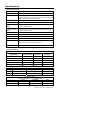
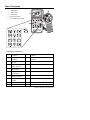
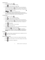
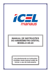
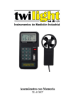
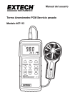
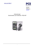
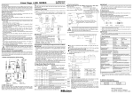
User's Guide
Vane Thermo-Anemometer Datalogger
Model 451126
Introduction
Congratulations on your purchase of Extech's Thermo-Anemometer Datalogger. This
Vane-type Anemometer can indicate Air Velocity in five units of measure: Feet per minute,
Meters per second, Miles per hour, Kilometers per hour, and Knots with Temperature
o
o
displayed in C or F units. The meter can also display air flow in CFM or CMM. The built-in
datalogger can record up to 2000 readings and the RS-232 interface provides PC data
transfer capability.
Specifications
General Specifications
Display
Dual 4-digit (9999 count) Multi-function LCD
Data hold
Locks latest reading on the LCD display
Sensor Structure
Air velocity sensor: Conventional twisted vane arm with low friction
(sapphire) ball bearing. Temperature sensor: K-type thermocouple
built into vane. 1/4" mounting nut provided
Memory Recall
Records Max/Min readings with push-key RECALL
Data Output
RS-232 PC serial interface
Operating conditions
(Meter)
Temperature: 32°F to 122°F (0°C to 50°C); Humidity: <80% RH;
Operating conditions
(Vane)
Temperature: 32°F to 140°F (0°C to 60°C); Humidity: <80% RH;
Pressure: 500mB to 2 Bar
Storage temperature
Temperature: -40°F to 140°F (-40°C to 60°C)
Power Supply
9V battery; Battery life: 50 hours typical
Power Consumption
Approx. 3 mA DC
Weight
0.77 lbs. (350g)
Dimensions
Meter: 3.46 x 6.61 x 1.03" (88 x 168 x 26.2mm);
Pressure: 500mB to 2 Bar
Vane: 2.6 x 5.22 x 1.15" (66 x 132 x 29.2mm)
Accessories
9V battery and carrying case
Range Specifications
Air Velocity
Measurement
Feet per Minute (ft/min)
Calibrated Range
60.0 to 8800
Display
Resolution
0.1
Accuracy
± (3% + 20 ft/min)
Meters per Second (m/s)
0.30 to 45.00
0.01
± (3% + 0.1 m/s)
Kilometers per Hour (km/hr)
1.00 to 140.0
0.01
± (3% + 0.4 km/hr)
Miles per Hour (mile/hr)
0.70 to 100.0
0.01
± (3% + 0.2 mile/hr)
0.60 - 88.0
0.01
± (3% + 0.2 knots)
Knots
Units
o
C
Range
o
o
0.0 C to 45.0 C
o
o
F
Temperature
Converter Resolution
o
0.2 C
o
o
32.0 F to 113.0 F
3
CFM (ft /min)
3
CMM (m /min)
0.4 F
Air Flow and Area
(CMM: 0 to 45.00 m/s; CFM: 0 to 8800 ft/min)
Range
Resolution
0 to 999900
0.001 to 100
0 to 999900
0.001 to 100
2
Accuracy
o
±1.0 C
o
±1.8 F
Area
0.001 to 9999
0.001 to 9999
Model 451126 Version 1.6 February 2004
Meter Description
1.
LCD Display
2.
Vane Sensor
3.
ON/OFF Key
4.
RS-232 Connector
5.
Function/Numeric Keypad
LCD Display Icon Definitions
AVE
Average reading mode
is selected
o
C
Temperature is displayed in degrees
centigrade
MIN
Minimum reading mode
is selected
o
F
Temperature is displayed in degrees
Fahrenheit
2/3V
2/3V Maximum mode is CFM
selected
Cubic feet per minute (ft /min)
MAX
Maximum reading
mode is selected
CMM
Cubic meters per minute (m /min)
VEL
Air Velocity
measurement
x100
Multiply reading by one hundred
READ
Recalling stored
measurements
X10
Multiply reading by ten
REC
Appears when
recording readings
m/s
Meters per second
ft/min
Feet per minute
RS-232 PC Interface is
activated
2
ft
2
m
3
3
Square feet
MPH
Miles per hour
Square meters
Km/h
Kilometers per hour
3
Model 451126 Version 1.6 February 2004
Operation
NOTE: For all air velocity or flow measurements, the air should pass through the vane
from back to front. The rear of the vane can be found by locating the mounting nut. The
front of the vane has the engraving "ANEMOMETER". For more accurate results, maintain
o
a 20 axis of air direction with the rear of the vane (refer to Fig.2).
Side view
of Vane
Air Velocity
1.
2.
Power the meter by pressing
.
20
Select Air Velocity measurement
function by pressing
o
Air direction
. VEL will
20
appear on the LCD.
o
Tripod mount
3.
Press
to select the desired unit
of measure (ft/min, mph, km/h, m/s or
knots)
4.
Place the vane in the air flow with the
Figure 2
air direction matching the direction of
the arrows printed on the inner walls
of the vane. If the unit does not have the printed arrows, have the tripod mount side
of the vane facing the air flow (see Fig.2).
5.
Air velocity will be displayed on the bottom line of the LCD.
Temperature
1.
When the meter is measuring Air Velocity, Temperature is simultaneously being
measured by the vane's built-in type-K thermocouple.
2.
Press
LCD.
to select °C or °F. Temperature is displayed on the upper line of the
Air Flow
1.
Power the meter by pressing
.
2.
Press
to select airflow. FLOW will display.
3.
Press
to select the desired unit of measure. (CFM, CMM).
4.
To enter the area value, press
. The lower display line will blank waiting for
the user to program new data. Use the numeric keys to enter a new area value in
square feet. (REMINDER: if measurement is taken in inches, divide by 144 to
obtain square feet). Press
when finished.
Airflow is based on the specific dimensions of the duct being measured. For the
meter to correctly measure CFM the user must input the area of the duct. Failing to
input the correct area dimensions will result in erroneous readings.
NOTE: If the AVE or the 2/3MAX display icons are displayed in the upper left hand
corner of the LCD, press
until they extinguish.
5.
6.
7.
Place the vane in the air flow (Fig.2).
Wait approximately 2 seconds for a stabilized Air Flow reading.
The equation below is used to calculate Air Flow:
AIR FLOW = (AIR VELOCITY) x (AREA)
4
Model 451126 Version 1.6 February 2004
2/3Vmax Air Flow
1.
Power the meter by pressing
2.
Press
to select Air Flow. FLOW will display.
3.
Press
to select the desired units (CFM, CMM).
4.
.
The previously stored area value will be displayed on the upper LCD display line.
To enter a new area value press
. The lower display line will blank waiting for
the user to program new data. Use the numeric keys to enter a new area value in
square feet. Press
when finished.
5.
Press
6.
Determine the direction of the air to be measured. Move the Vane around the
center of the area being measured to read the maximum air velocity. The meter will
use the maximum reading obtained to determine the 2/3MAX Air Flow.
until the 2/3V MAX icon appears on the LCD.
Average Air Flow
1.
Power the meter by pressing
2.
Press
to select Air Flow. FLOW will display.
3.
Press
to select the desired units (CFM, CMM).
4.
.
The previously stored area value will be displayed on the upper LCD display line.
To enter a new area value press
. The lower display line will blank waiting for
the user to program new data. Use the numeric keys to enter a new area value.
Press
when finished.
5.
Press
until AVE appears on the LCD display.
6.
Press
to clear the upper LCD.
7.
Select a measurement location. Once a point is selected and a flow measurement
is displayed, press
to average the flow reading.
8.
Select the next measurement location and press
again to average the
reading with previous readings. The value in the upper LCD line will increment for
each reading taken to show how many readings were averaged. The max is 12
readings.
Data Hold
Press
to freeze the reading. The display will hold and an 'H' will appear on the LCD.
Press
again to return to normal operation.
MAX and MIN Measurements
1. Press
to enter MAX mode. The meter will only display the highest reading.
2. Press
again to enter the MIN. The meter will only display the lowest reading.
3. Press
to exit the MAX or the MIN mode.
5
Model 451126 Version 1.6 February 2004
Datalogging
Instantaneous (One-Shot) Datalogging
To record one data point at any desired time, set the sampling rate = 0 by pressing
in the VEL mode. The previously stored reading will be displayed on the upper LCD line.
Enter a '0' sampling time and then press
. Now, each time
is pressed, the
present reading will be stored in non-volatile memory.
Automatic Datalogging
1. Set the Sampling rate for datalogging by pressing
. The previous sample
rate will appear.
2. Enter a value from 1 to 240 seconds using the numeric keypad. Press
when
done.
3. Press
to begin storing readings in non-volatile memory every n seconds (n =
the value entered in step 2. above).
4. The REC icon will appear on the LCD indicating that the datalogging mode is
activated.
5. The maximum number of readings that can be stored is 2000.
6. To stop datalogging, press
again. The datalogger will automatically stop
recording data when 2000 records have been stored.
See software section of this manual for instruction on viewing logged data.
IMPORTANT NOTE: If power is removed before datalogging is properly halted,
data will be lost.
Reading Stored Data Sequentially
Press
, the RECORD NUMBER will briefly display on the upper LCD line before
the measurement data appears. Press
to return to normal operation.
Reading Stored Data Randomly
1. Press
to enter the READ mode.
2. Press
and enter the number of the record in question.
3. Press
again and the desired data will be displayed.
4. Press
to return to normal operation.
Clearing Datalog Memory
Press and hold
memory.
while powering up the meter to clear the meter's datalog
6
Model 451126 Version 1.6 February 2004
Software
The 451126 software lets the user:
•
Download logged recordings from the meter’s memory
•
Record to the PC
•
Graphically display readings from the meter
System Requirements
Hardware Requirements: 486 PC or better with COM 1 and COM 2 Serial ports
Operating System Compatibility: Windows
TM
95/98/NT/2000/XP
Hardware Connection
The IR Thermometer connects to a PC with the supplied DB-9 to DB-9 interface cable.
Software Installation
The instructions on how to install the optional software are printed on the Software CD
label. After reading the label’s directions, load the software CD in the PC CD-ROM drive.
7
Model 451126 Version 1.6 February 2004
Starting the Software
1. Run the program by opening the program named “Flow
Anemometer”.
Flow Anemometer is in the programs folder of your
Windows software.
2. Wait for the program to initialize and select COM 1 or 2
as required.
The program will load and the main display will appear.
A red NO COM icon will flash on the bottom right hand
side of the display.
3. Press and hold
then power on the meter by
pressing
The RS232 icon will appear on the upper right hand side
display of the meter.
The NO COM icon will disappear.
Communications has been established.
Values will appear in the diplay.
8
Model 451126 Version 1.6 February 2004
Operating the Software
Graphical Display Mode
The display command offers 5 different displays.
Click Display on menu bar to select.
Click Option to set Upper and Lower Limits. The software will then flag readings exceeding
the limits.
Main Display
Digital Display
Click Reset button on main
display to clear Min/Max
Analog Display
Graphical Display
Click Scale in Graphical Mode
to change x and y axis scale.
List Display
9
Model 451126 Version 1.6 February 2004
Data Acquisition Mode
In data acquisition mode the meter is connected to a PC with the data being saved
directly to the PC’s memory.
1.
In the Flow Anemometer
program, click File, and then
click Name. Enter a file name
and click OK
2.
Click Option then Sample,
enter a sampling interval and
then click OK
3.
Click File then Start
Recording.
4.
To stop the meter click File
then click End Recording.
10
Model 451126 Version 1.6 February 2004
Viewing Files
Files can be view in table form or they can be plotted on a graph.
Viewing in a table:
5.
In the Flow Anemometer program, click File, and then click View File.
6.
When the View screen opens click File then click Open.
7.
In the Look in list, click the drive, folder, or Internet location that contains the file
you want to open.
8.
In the folder list, locate and
open the folder that contains
the file. The File will then
open. Click File then Print
to print records
Plotting a graph
1.
In the Flow Anemometer program, click File, and then click Plot Data from File.
2.
When the Plot Data screen opens click File then click Open.
3.
In the Look in list, click the drive, folder, or Internet location that contains the file
you want to open.
4.
In the folder list, locate and
open the folder that
contains the file. The File
will then open. Click Print
to print the graph. The
graph can also be
modified and manipulated
by using the graphing
commands.
11
Model 451126 Version 1.6 February 2004
Downloading Logged Data to the PC
Note: The RS232 communication symbol should NOT be displayed in the LCD when
downloading.
1.
Click Datalogger on the menu.
The Datalogger Anemometer
screen will open.
2.
Click the Download button. The
Log File screen will open.
Enter a File name and click OK
button.
The Status screen will open.
Status screen will count up the number of
readings being transferred.
3.
Press
to initiate data transfer from
the meter to the PC
4.
When transfer is completed click OK.
5.
The datalogger screen will appear
and display the number of records
and the sampling rate they were
taken at.
6.
Click File and Exit. Data can now be
viewed
12
Model 451126 Version 1.6 February 2004
Useful Equations and Conversions
Area equations
Circular Duct
Rectangular Duct H
Area = W x H
R
A= π R
(A= 3.14 x R x R)
2
W
Cubic equations
3
2
CFM (ft /min) = Air Velocity (ft/min) x Area (ft )
3
2
CMM (m /min) = Air Velocity (m/sec) x Area (m ) x 60
Units Conversion Table
1 m/s
m/s
ft/min
knots
km/hr
mph
1
196.87
1.944
3.6
2.24
1 ft/min
0.00508
1
0.00987
0.01829
0.01138
1 knot
0.5144
101.27
1
1.8519
1.1523
1 km/hr
0.2778
54.69
0.54
1
0.6222
1 mph
0.4464
87.89
0.8679
1.6071
1
13
Model 451126 Version 1.6 February 2004
Battery Replacement
The low battery indicator appears on the LCD display when it is time to replace the 9V
battery, which powers the meter.
To replace the battery:
a. Turn the meter off.
b. Remove the battery compartment screw and remove the battery compartment
cover.
c. Replace the 9V battery and reinstall the compartment cover.
d. Fasten the compartment screw
14
Model 451126 Version 1.6 February 2004
Appendix A: Real-time Datalog-to-PC transfer
Byte 1 0D (Hex)
Byte 9
Byte 2 bit4: Velocity OL, bit5 Area OL, bit 6:
Byte 10
Temp OL
Byte 3 0: m/s, 1: ft/min, 2: knots, 3: km/hr, 4: MPH Byte 11
Byte 4
bit2: MAX, bit3: MIN, bit4: 0:VEL 1:FLOW,
bit 5: 0: DEG C, 1:DEG F, bit7: RS-232
enabled
Byte 5 bit0: 0:CMM, 1: CFM, bit3: low batt, bit4:
Temp OL,
bit5: AVE, bit6: 2/3Vmax, bit7: Instant
Byte 6 Lower LCD decimal, bit0: x100, bit1: x10,
bit2: x1,
bit3: dp1 (rightmost), bit4: dp2, bit5: dp3
(leftmost)
Byte 7 Upper LCD decimal, bit2: x1, bit3: dp1
(rightmost),
bit4: dp2, bit5: dp3 (leftmost)
Byte 8 Digit 3 (MSD) in upper LCD
Appendix B: Transferring Logged Data to the PC
Byte 0
0D (hex)
Byte 772
Byte 12
Digit 2 in upper LCD
Digit 1 in upper LCD
Digit 0 (LSB) in upper
LCD
Digit 3 (MSB) in lower
LCD
Byte 13
Digit 2 in lower LCD
Byte 14
Digit 1 in lower LCD
Byte 15
Digit 0 (LSB) in lower
LCD
Digit 3 (MSB) in lower LCD
Byte 1
Calibration Data 0
Byte 773
Digit 0 (LSB) in upper LCD
Byte 2
Calibration Data 1
Byte 774
Digit 1 in upper LCD
Byte 3
Calibration Data 2
Byte 775
Digit 2 in upper LCD
Byte 4
Sampling time
Byte 776
Digit 3 (MSB) in upper LCD
Byte 5
Last record no. (low
byte)
Byte 777
Upper LCD decimal, bit2: x1,
bit3: dp1 (rightmost), bit4:
dp2, bit5: dp3 (leftmost)
Byte 6
Last record no. (high Byte 778
byte)
Lower LCD decimal, bit0:
x100, bit1: x10, bit2: x1, bit3:
dp1 (rightmost), bit4: dp2,
bit5: dp3 (leftmost)
Byte 7
Free area (low byte) Byte 779
bit0: 0:CMM, 1: CFM, bit3: low
batt, bit4: Temp OL, bit5:
AVE, bit6: 2/3Vmax, bit7:
Instant
Byte 8
Free area (high
byte)
bit2: MAX, bit3: MIN, bit4:
0:VEL 1:FLOW,
Byte 780
bit 5: 0: DEG C, 1:DEG F,
bit7: RS-232 enabled
Byte 9
Decimal pt. for area
(refer to byte 778)
Byte 781
0: m/s, 1: ft/min, 2: knots, 3:
km/hr, 4: MPH
Byte 10 - 768 Reserved
Byte 782
bit4: Velocity OL, bit5 Area
OL, bit 6: Temp OL
Byte 769
Digit 0 (LSB) in
lower LCD
Byte 783
Not used
Byte 770
Digit 1 in lower LCD
Byte 784
Not used
Byte 771
Digit 2 in lower LCD
Byte 785 32768
Record No. 2 to Record No.
2000
15
Model 451126 Version 1.6 February 2004
Warranty
EXTECH INSTRUMENTS CORPORATION warrants this instrument to be free of defects
in parts and workmanship for one year from date of shipment (a six month limited
warranty applies on sensors and cables). If it should become necessary to return the
instrument for service during or beyond the warranty period, contact the Customer
Service Department at (781) 890-7440 ext. 210 for authorization or visit our website at
www.extech.com (click on ‘Contact Extech’ and go to ‘Service Department’ to request an
RA number). A Return Authorization (RA) number must be issued before any product is
returned to Extech. The sender is responsible for shipping charges, freight, insurance
and proper packaging to prevent damage in transit. This warranty does not apply to
defects resulting from action of the user such as misuse, improper wiring, operation
outside of specification, improper maintenance or repair, or unauthorized modification.
Extech specifically disclaims any implied warranties or merchantability or fitness for a
specific purpose and will not be liable for any direct, indirect, incidental or consequential
damages. Extech's total liability is limited to repair or replacement of the product. The
warranty set forth above is inclusive and no other warranty, whether written or oral, is
expressed or implied.
Calibration and Repair Services
Extech offers repair and calibration services for the products we sell. Extech also provides
NIST certification for most products. Call the Customer Service Department for information
on calibration services available for this product. Extech recommends that annual
calibrations be performed to verify meter performance and accuracy.
Support Hotline (781) 890-7440
Tech support: Ext. 200; Email: [email protected]
Repair/Returns: Ext. 210; Email: [email protected]
Website: www.extech.com
Copyright © 2004 Extech Instruments Corporation
All rights reserved including the right of reproduction in whole or in part in any form.
16
Model 451126 Version 1.6 February 2004