Transcript
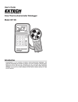
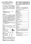
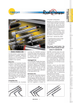
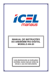
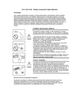
No.99MBC091B1
Series No. 575
Linear Gage LGS SERIES
Introduction
Tip
To obtain the highest performance and the longest service life from your
Linear Gage, carefully read this User’s Manual thoroughly prior to setup
and operation. After reading this manual keep it near the Linear Gage for
quick reference. The specifications of this gage and the description in this
manual are subject to change without prior notification.
The ABS origin point has been set near the lowest end of the stroke
before shipment.
15
1
7.5
・Example 1.
IMPORTANT
Please be careful enough when handling the knife edge or
blade type contact point, since there is a possibility of injury at
exchange and use.
Electromagnetic Compatibility(EMC)
This product complies with the EMC Directive. Note that in environments
where electromagnetic interference exceeds EMC requirements defined
in this directive, appropriate countermeasures are required to assure the
product performance.
1. Name and Dimension of Each Part
・REQ, ORIG
Vdd
4.5 drill, 7.5 countersink,
4.4 deep
cross section
φ 8H7
15
20
・Example 2.
φ
7.5
10
+0.015
10H7 0
φ 8H7
+0.015
0
Since the power voltage differs between the gage side and an
external device side, absolutely use an open collector or open
drain circuit. Do not use a CMOS output, etc.
15
1
cross section
IMPORTANT
d1
θ
• Avoid pressing the stem directly with set
screws. If the screws are fastened tightly, the
spindle will not slide properly.
• Mount the gage so that the spindle is directed
perpendicular to the measured surface. If the
gage is mounted at an oblique angle to the
measured surface, an error may be
generated in measurement results.
10
10
2
Signal
・Applicable receptacle on the external
device side
Sumitomo 3M:V Low-Proheader
Model:7610-5002XX or equivalent
In/Out
Description
1
GND
-
Signal ground
2
DATA
Out
Measurement data-output terminal
d8
Decimal point position
(0 to 5)
Example:0→000000.
1→00000.0
5→0.00000
as a BCD in positive logic (0 = L, 1 = H).
4) Timing chart
t5
t6
DATA
t2
t3
t4
t8
ACTIVE
t10
t11
Symbol
min.
max.
Symbol
*t1
30µs
95ms
*t7
t2
15µs
-
t3
100µs
-
*t11
Out
Synchronized clock-output terminal
t4
100µs
-
-
Unused
t5
0µs
-
5
REQ
In
*t6
-
100µs
In
N.C.
-
Absolute origin setup signal input terminal
Unused
* 8
N.C.
-
Unused
* 9
+5V
-
Power supply terminal(+5V±10%)・・・Note2
*10
GND(F.G.)
-
Frame ground
Note 1: * indicates pin assignment dedicated only to this instrument
Other pin assignments are based on specitications common to
Digimatic outputs(10-pin square connector specifications).
Note2: Consumption current of this instrument: ldd=20mA max.
t7
CK
CK
ORIG
b) Insert a rubber boot between the stem and contact point, directing the
greater inside diameter end to the stem.
c) Apply a small amount of silicone adhesive to the grooves (part A),
and seal both ends of the rubber boot.
If the adhesive is applied to the spindle slider, the spindle will not slide
properly. Great care must be exercised.
Order No.
Model
Measuring range
Resolution
Accuracy(at 20℃)※1
Stem diameter
Contact point
Protection level ※2
Measuring force
Contact point downward
Contact point horizontal
Contact point upward
Positional sensor
Response speed
REQ
t1
Rubber boot contact point
7. Specifications
is outputted sequentially from LSB to MSB.
N.C.
* 7
d10 d11 d12 d13
● Measurement data is outputted sequentially from MSB to LSD.
● A sign, measurement data, decimal point position, and unit are outputted
3
* 6
d9
Measured data
* 4
Input terminal for data transmission request
KeyWay
bits=1digit.
Absolute
origin set
operation
2
d7
● The data is outputted sequentially, starting from d1 to d13. Also, each digit
ORIG
1
d6
● Each piece of measurement data consists of 13 digits (52 bits) as 4
1) Pin assignments and signals
9
d5
Unit(mm:0、inch:1)
5. Gage Output Signal Specifications
9
d4
Sign(+:0、-:8)
• The output connector plug (counter side) is not protective structured.
Install the gage at a place where it is not splashed directly with water
or oil.
• If the cable covering is broken, liquid will penetrate into the gage inside
due to capillary phenomenon. This will cause damage to the gage.
• Be greatly careful not to damage the rubber boot due to chips, etc. If
the rubber boot is damaged, dust-proof and water-proof function will
be deteriorated. Immediately replace or repair the rubber boot.
• The materials including rubber which are used for the rubber boot and
other sealing parts are not universal against diversified coolants and
chemicals. If those parts deteriorate unusually, consult the nearest
Mitutoyo Service Center.
• Each part of the gage is sealed up, and therefore must not be
disassembled. If any part is disassembled, the rated performance will
not be obtained. Do not absolutely disassemble the gage.
1
d3
Error=L0-L1
From external device
With this absolute sensor, the origin point cannot be reset even if the
power is turned off. When the power is turned on, the sensor always
outputs its positional data relative to the origin point. For the detailed
method, refer to the User’s Manual for the using counter.
d2
All “F”
4. Precautions in Protecting the Gage from Dust and Water
IMPORTANT
(A)
IMPORTANT
3) Data format
Notch position
(90°with respect to tap)
Pin No.
2. ABS Origin point
Spindle
0
φ 10H7 -0.015
M4×0.7 thru
①
(A)
Stem
Tr
②Split bushing
①
②
Tr=NPN open collector or N-ch open drain(2SC2855, etc.)
"L" level output voltage:VOL=0.2Vmax.(at IOL=10mA)
"H"level leak current:ILK=2μAmax.(at VOH=5.5V)
R1
CMOS
input
+0.015
0
15
• Do not apply sudden shocks including a drop or excessive force to the
Linear Gage
• Do not disassemble or modify the gage.
• Do not use and store the gage at sites there it is exposed to direct
sunlight or at extremely hot or cold sites.
• To use the gage highly accurately, avoid sites where the temperature
will change abruptly.
• Absolutely do not apply an electric engraver to the gage. The high
voltage may damage electronic parts. Also, do not use the gage at
sites where it is subject to large electronic noises.
• Do not exert load on the spindle in the perpendicular direction and do
not twist the spindle.
• Do not clamp the stem too tightly, since the spindle will not move
smoothly.
• Do not apply excessive tension to the cable or do not bend it forcibly.
• Allow at least a few seconds after turning on the power.
• If the gage is used in combination with other instruments, the maximum
performance could not be obtained depending on environment and
operating conditions. Take those conditions into consideration prior to
use.
• The functions and performance will not be guaranteed, if the gage is
used in other conditions than those specified.
• Take sufficient damage-preventive processing (safety measures),
should the gage have been at fault.
unit:mm
7.5
15
Carefully avoid the following attempts to protect the instrument from
failure and malfunction.
16
M4×0.7 thru
Precautions for Use
6
To ensure operator safety, use the instrument in conformance with the
directions and specifications given in this manual.
(1) To mount the gage on another instrument or a fixture, clamp the ø8
stem
(2) It is recommended to use a slotted holder or a split bushing for the
mount structure. (Recommended tightening torque in Example 1: 4.0
to 5.0kgf·cm)
6
Safety Precautions
3. Mounting the Gage
2) Electrical specifications
IMPORTANT
●Output terminal type: CK, DATA ●Input terminal type: REQ、ORIG
If this linear gage is used with the gage cable close to the power lines of
Pull-up CMOS input
N-ch open drain
other devices, it will result in a gage malfunction. Be sure to separate
Internal power supply voltage:
Max. output current: 400µAmax
the gage cable from the power lines.
( At VoL = 0.4V )
Vdd=1.35 to 1.65V
Output withstand voltage:-0.3 to 7V Pull-up resistance:R1=10 to 100kΩ
6. Maintenance
"H" level input voltage: VIH=1.1Vmin.
"L" level input voltage:VIL=0.3Vmax. 1) Replacing the contact point
Detach or attach the contact point by pinching it with a key spanner, etc.
LG side
Recommended I/F on the external device
2) Replacing the rubber boot
Vcc
For Vcc=5V system
side
Preventive replacement before being damaged is recommendable.
・CK, DATA
R1、R2=22kΩ ±10%
R1
74HC14
(The rubber boot is available as an optional accessory.)
C=330pF±20%
a) Remove the old rubber boot, then eliminate the dust and dirt in the
等
R2
C
grooves (part A) or the stem and spindle.
min.
max.
100µs
-
*t8
-
30ms
*t10
1.5s
-
-
4s
Note1: * indicates a specification dedicated only to this instrument. All other
Digimatic output specifications are common to all models.
Note2: Read the data when the CK is at the L level.
Note3: While setting the absolute origin (during t11), do not input the REQ
signal.
Note4: If t5, t6 and t7 are satisfied and REQ is continuously input, an output is
obtained from LGD at intervals of approximately 95ms.
Note5: Start inputting the ORIG and REQ in approximately2 or 3 seconds
(estimated time for built-in circuitry/sensor stabilization) after turning
on the power.
575-303
LGS-1012P
12.7mm
0.01mm
0.015mm
φ8mm
φ3carbide ball
575-313
LGS-1012PE
.5”
.0005”
.0006”
φ9.52mm=3/8”DIA
φ3carbide ball
(Thread:M2.5x0.45)
(Thread:#4-48UNF)
IP66 (Apply only for gage head)
2N or less
1.8N or less
1.6N or less
Capacitance-type absolute linier encoder
Infinite; measurement by scanning can
not be performed
Digimatic output
Slide-bearing type
2m (directly wired from the gage)
±1count
0 to 40℃ (20 to 80%RH, with no condensation)
Output method
Bearing type
Output cable length
Quantizing error
Operating
temperature(Humidity)
Storage temperature(Humidity) -10 to 60℃ (20 to 80%RH, with no condensation)
Mass
190g
Standard accessory
No.99MBC091B (This instruction manual)
CE marking
EMC Directive:EN61326-1
Immunity test requirements: Clause 6.2 Tabel2
Emission limit: Class B
※1: Quantizing error is not included.
※2: IP(International Protection) is conformed to IEC60529/JIS C0920
The unit may not be able to maintain resistance to certain types of
liquids.
8. Optional Accessories
(must be purchased separately)
P ar t n am e
Rubber boot
Order No.
No.238774
Mitutoyo Corporation
20-1, Sakado 1-Chome, Takatsu-ku,
Kawasaki-shi, Kanagawa 213-8533, Japan