1
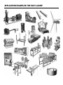
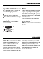
Manual
05-0100 Rev7
Display unit D279
D200 Sheave/Pulley Alignment
D450 Shaft Alignment
D505 Shaft Alignment
D525 Shaft Alignment
D600 Machine
D630 Extruder
D650 Linebore
D660 Turbine
D670 Parallelism
D800 Machine SpinLaserTechnology™
Damalini AB
Åbäcksgatan 6B
431 67 Mölndal, Sweden
Tel +46 31 708 63 00
Fax +46 31 708 63 50
e-mail: [email protected]
www.damalini.com
© 2005 Damalini AB. Changes may be made without further notice.
Windows®, Excel® and Works® are registered trademarks of the Microsoft Co.
Lotus® is a registered trademark of the Lotus Development Co.
APPLICATION EXAMPLES FOR EASY-LASER®
System
A
Handling
B
Programs
C
Applications
D
Basics
E
Appendix
F
TABLE OF CONTENTS
A. System
Complete systems ............................................. A2
Complete systems ............................................. A3
Complete systems ............................................. A4
Display unit D279 ............................................... A5
Spinning laser D23 ............................................. A6
Sviwelling laser D22 ........................................... A7
Laser D22 and D23: calibration of vials ............... A9
Spindle laser D146 ........................................... A11
Laser transmitter D75 ....................................... A13
Measuring units S, M: PSD 18x18 mm .............. A15
Measuring units S, M: PSD 10x10 mm .............. A17
Detector D5 ...................................................... A19
Detector D157 .................................................. A20
Detector D6 ...................................................... A21
Large target Base line, Tripod .......................... A22
90° Angular prism D46 ..................................... A23
90° Angular prism D46: calibration .................... A24
Shaft brackets ................................................... A25
Sliding bracket .................................................. A26
Magnet base D45, Cable support .................... A27
Accessory brackets .......................................... A28
Cardan brackets ............................................... A29
Turbine fixtures etc. .......................................... A30
Linebore system: coordinate hub ...................... A31
Linebore system: detector ................................. A32
Extruder fixtures etc. ......................................... A33
BTA Digital: laser transmitter .............................. A34
BTA Digital: detector unit .................................... A35
Printer Kyoline BAT .......................................... A36
Vibrometer Probe D283 .................................... A37
Instruction Tilting screws ................................... A38
B. Handling the display unit
Main menu ......................................................... B2
Help menus ........................................................ B3
Store measurement result ................................... B4
Restore and Delete measurement result .............. B5
Printouts and PC transmitting ............................... B6
EasyLink™ PC software for Windows ................. B7
Measurement value filter ................................... B19
Programming the laser (D22, D75, D146) ........ B20
C. The measurement programs
Introduction to shaft alignment .............................. C2
Mounting the measuring units .............................. C3
Rough alignment ................................................ C4
Shaft alignment: enter the distances ..................... C5
Program 11, Horizontal ....................................... C6
Measurement result for horizontal machines ........ C8
Tolerance Check ................................................ C9
Thermal Growth Compensation ........................ C10
Program 12, Easy-TurnTM. ............................... C12
Program 13, Softfoot ......................................... C15
Program 14, Cardan ........................................ C16
Program 15, Vertical ......................................... C20
TABLE OF CONTENTS
Program 16, Offset and Angle ........................... C22
Program 17, Values .......................................... C24
Program 18, Machine train ............................... C26
Program 19, Vibrometer ................................... C31
Program 21, Spindle ........................................ C36
Program 22, Straightness ................................. C39
Program 23, Center of Circle ............................ C42
Program 24, Flatness ....................................... C46
Program 25, Plumbline ..................................... C49
Program 26, Squareness ................................. C53
Program 27, Parallelism .................................... C55
Program 28, Flange ......................................... C58
Introduction to sheave alignment ....................... C60
Program 29, BTA Digital .................................... C61
Program 31, Half Circle .................................... C67
Program 34, Straightness Plus .......................... C71
Program 35, Center of Circle Plus ..................... C74
Program 36, Half Circle Plus ............................. C78
Program 38, Parallelism Plus ............................ C82
D. Measurement applications
Straightness ....................................................... D2
Flatnesss ............................................................ D3
Squareness measurement with indexing ............. D4
Straightness measurement with S- and M-unit ..... D5
Pointing direction ................................................ D6
Aligning of workpiece .......................................... D7
E. Measurement basics
Facts about laser ................................................ E2
Facts about PSD ................................................ E3
Divergence and Laser beam center .................... E4
Thermal gradients .............................................. E5
Measurement and alignment ............................... E6
Technical terms ................................................... E7
Conditions for shaft alignment .............................. E8
Shaft alignment methods .................................... E10
Mathematical principles of shaft alignment .......... E11
Center of rotation .............................................. E12
Angular deviation ............................................. E14
Measurement principles for geometry ................ E15
Straightness – reference points ......................... E16
F. Appendix
Tolerances for shaft alignment .......................... F2
Tolerances for sheave alignment ....................... F3
BTA Digital: calibration ...................................... F4
Checking the units ............................................. F5
Conversion tables .............................................. F6
Problem solver, Maintenance .............................. F7
Notes ................................................................. F8
DECLARATION OF CONFORMITY
Declaration of Conformity
Equipment:EASY-LASER® PRODUCT RANGE
Damalini AB declares that the Easy-Laser® product range is manufactured in conformity with
national and international regulations.
The system complies with, and has been tested according to the following requirements:
EMC Directive:
89/336/EEC
Low Voltage Directive: 73/23/EEC
including amendments by Directive 93/68/EEC.
Laser Classification:
EUROPE SS-EN-608 25-1-1994
USA
CFR 1040.10/11 - 1993
Year 2000 compliance:
The manufacturer declares that the equipment mentioned above including all software and
firmware delivered with the equipment complies with the Swedish IT Commissions Year 2000
definition.
1 February 2000, Damalini AB
Leif Törngren, Development
SAFETY PRECAUTIONS
Easy-Laser® is a laser instrument in laser class II
with an output power less than 1 mW, which only
requires the following safety precautions:
!
Never stare directly into the laser beam
Never aim the laser beam at anyone else’s eyes.
NOTE! Opening the laser units can result in
hazardous radiation, and will in validate the
manufacturer warranty.
Warning!
If starting the machine to be measured would result
in injuries, the possibility to unintentionally start it
must be disabled before mounting the equipment,
for example by locking the switch in the off position
or removing the fuses.
These safety precautions should remain in place
until the measurement equipment has been removed from the machine.
NOTE! The system should not be used in explosive
risk areas.
DISCLAIMER
Damalini AB and our authorized dealers will take
no responsibility for damage to machines and
plant as a result of the use of Easy-Laser®
measurement and alignment systems.
Even though great efforts are made to make the
information in this manual free from errors, and to
make the information complete for the user, there
could be things we have missed, because of the
large amount of information. As a result of this, we
might change and correct these things in later
issues without further information. Changes to the
Easy-Laser® equipment may also affect the
accuracy of the information.
DAMALINI AB
Easy-Laser®: measurement equipment for
your needs
Damalini develops and manufactures Easy-Laser®
for measurement and alignment of machinery and
plant. We have more than 20 years of experience
from measurement tasks in the field and product
development. We also provide measurement service, which means that we ourselves use the
equipment we develop, and continuously improve
it. Because of this we dare to call ourselves
measurement specialists.
Measurement service and training
Don not hesitate to contact us about your
measurement problems. Our expertise will help you
solve it in an easy way. For specific customer
applications we develop customized systems. For
the latest information, you are welcome to visit our
web site.
Easy-Laser® around the world
Damalini products are used in more than 40
countries around the world. This means that as a
user of Easy-Laser®, you have a lot of
companions. For us this is the best source for
improvements to the equipment. Wherever you
are, we look forward to helping you with your
measurement and alignment tasks!
Development department.
Measurement training.
Our products are used all around the world.
UPGRADABILITY
Systems and parts
The Easy-Laser® systems are designed to grow as the needs
increase. Measurement systems D450 and D505 have as standard when delivered only programs for shaft alignment, and all
other systems with Display unit D279 have all programs (see
next page). Starting with Display unit D279 you can measure
virtually anything by combining different fixtures, lasers,
measuring units and detectors, and also expand the
measurement software in some cases. You can start with a Shaft
alignment system, and then expand the system for geometry
measurements. In the same way you can start with a Geometry
system and expand it with equipment for shaft alignment.
Schematic picture of the parts included in the
Easy-Laser® measurement product range.
Measuring units
S-units
1-axis
1-axis, Inclinometer
2-axis, Inclinometer
Vibrometer probe
D283
M-units
1-axis
1-axis, Inclinometer
2-axis, Inclinometer
PC
Printer
Lasers
Spindle laser D146
Detector D157
Universal laser D75
Detector D5
Swivelling laser D22
Display unit D279
(Note! Depending on
software configuration.)
Angular prism D46
Tripod
Detector D6
Magnetic bases
SpinLaserTechnology
Brackets
Thin shaft brackets
Sliding brackets
Magnetic brackets
Standard shaft brackets
with chains
Cardan brackets
Laser transmitter
D23
SpinLaserTechnology
MEASUREMENT PROGRAMS
Measurement programs configurations
These pages describe which programs and functions the Display unit D279
has for the different measurement systems. There is also a brief description of
each program.
D525
D600
D630
D650
D660
D670
D800
D450
D505
Horizontal - For shaft alignment of horizontal machines with the 9-12-3 method.
X
X
X
Softfoot - With this program you can check that the machine is standing on all
feet. Displays which foot to correct.
X
X
X
EasyTurnTM - For shaft alignment of horizontal machines.
Requires only 20° between measurement points.
X
X
Cardan - Shows the angular misalignment and the adjustment value for
offset mounted machines.
X
X
Vertical - For measurement of vertical and flange mounted machines.
X
X
Machine train - For the alignment of two to ten machines in a row (nine
couplings). Shows the measurement values live during the alignment.
X
X
RefLock™ - Any two feet can be selected as references (locked).
Works as a sub function in the Machine train program.
X
X
Thermal growth compensation - Compensates for difference in thermal
growth between the machines. Works as a sub function in the Horizontal,
EasyTurn™ and Machine train program.
X
X
X
Tolerance check - Checks the offset and angle values towards selected
tolerance. Shows graphically when the alignment is within tolerance. Sub function.
X
X
X
X
X
X
X
X
Measurement Value Filter - Air with varying temperature may influence the
direction of the laser beam. The filter function produces stable readings also for
these conditions. Sub function in all programs except BTA Digital and Vibrometer.
Offset and Angle - This program displays the offset and the angular
misalignment between e.g. two shafts. Shows values from both 1-axis and 2axis measurement units. Also suitable for dynamic measurements.
MEASUREMENT PROGRAMS
D450
D505
D525
D600
D630
D650
D660
D670
D800
Values - This program displays the values from the detector in live mode, similar
to measurement with dial indicators. The values can be zeroed and halved. Up
to four units can be connected in series and can be zeroed individually.
X
X
Vibrometer - Shows vibration level in ”mm/s” or ”inch/s” and bearing condition
value in ”g”. The measurement complies with vibrations standard ISO10816-3.
X
X
BTA digital - For measurement and alignment of pulleys.
X
X
Straightness - For measurement of straightness on machine
foundations, shafts, bearing journals etc. Handles up to 150 measurement
points with two arbitrary zero points.
X
Straightness PLUS - Versatile program with advanced functions. Measurement points can be added, deleted or remeasured anytime during the measurement. The reference line can be offset set. For use as described above.
X
Flatness - Program for measurement of flatness/twist, for example on
machine foundations, machine tables etc. Handles up to 300 measurement
points with three zero points.
X
Squareness - For measurement of squareness in machinery and plant.
X
Parallelism - For measuring between rolls, machine sides etc. Handles
up to 150 rolls or other objects. Baseline or roll can be chosen as
reference. Each measurement object is given a specific name.
Parallelism PLUS - Versatile program with advanced functions. Measurement
objects can be added, deleted or remeasured anytime during the measurement.
Includes baseline measurement function. For use as described above.
X
X
Spindle - For measurement of centerline direction of machine spindles on
machine tools, drilling machines etc.
X
PlumbLine - With this program you measure plumbline and straightness
on turbine and generator shafts, for example.
X
Continued
➥
MEASUREMENT PROGRAMS
D450
D505
D525
D600
D630
D650
D660
D670
D800
Flange - For measurement of flatness on flanges and circular planes, for
example axial bearings. Up to 150 measurement points can be handled.
Three zero points with 120° in between are calculated by the system.
X
Center of circle - This program is used when measuring the
straightness of bearing journals. Allows varying diameters.
X
Center of circle PLUS - Versatile program with advanced functions. Measurement points can be added, deleted or remeasured anytime during the measurement. The reference line can be offset set. For use as described above.
X
Half-Circle - Measurement values are taken in the 9, 6 and 3 o’clock positions.
Allows varying diameters. To be used with the Turbine system.
X
Half-Circle PLUS - Versatile program with advanced functions. Measurement
points can be added, deleted or remeasured anytime during the measurement.
The reference line can be offset set. For use as described above.
X
Note! Display unit D279 can be upgraded and expanded with new software.
This means that above configurations is for standard systems.
X
X
X
GETTING STARTED
Manual
This manual describes in order:
The hardware parts:
Technical specifications and functions.
Handling the display unit:
Settings, button choices and measurement data handling.
Handling the measurement programs:
Measurement procedures step-by-step.
Measurement applications:
More examples of applications.
If you are unfamiliar with measurement and
alignment, we suggest that you first read the
chapter E- Measurement basics... before you start
using the system, and then go on from chapter A.
NOTE! In chapter C-Measurement programs
each step describes which button to press to
continue the measurement. Also there are
optional choices between brackets, for example:
[ Backstep
]
The basics of measurement and aligning:
The basics, technical terms etc.
Appendix:
Tolerances, Conversion tables, Problem solver.
Regarding the On/Off-button
:
When you are using a measurement program and
press the On/Off-button you will be directed to the
program menu again. You can now choose to
start another program and do another
measurement. If you will not use the display unit in
this mode it will automatically be shut down after
10 minutes. If you instead press the On/Off-button
again the display unit will be shut down
immediately.
(The display unit also has a general Auto-Off
function, see page B2.)
Continued
➥
GETTING STARTED
The picture shows two
measuring units (S, M)
connected to the display unit.
Shift to Program-menu page 2 by pressing
To get to the Main menu, press
Return to previous page by pressing the Menubutton once again.
(Possible in any situation, also during measurement.)
The first line of the Main menu says “Units found:”
shows whether the display unit is in contact with
all of the connected measuring units.
The measurement system
In the following way you connect the system to
learn how to handle it. For the description of each
laser, measuring unit etc, see chapter A.
1. Mount/place the equipment with suitable
fixtures on the measurement object.
2. Connect the cable to the display unit.
3. Connect the other end of the cable to any
measuring unit or detector. NOTE! You can use
any of the two connections on the units.
4. If you are using a shaft alignment system,
connect the other cable between the measuring
units S and M.
5. Start the display unit by pressing
. The first
thing displayed is the program menu. Start the
desired program by keying in the program number.
NOTE! If you connect two measuring units S and
M the laser lights up when a program is started. If
you have a detector and a separate laser transmitter you start the transmitter by pressing its Onbutton.
Rough alignment before measuring
6. Now aim the laser at the detector.
Start by aiming the laser at the closed target. (For
detailed description, see chapter C, “Rough
alignment” for shaft alignment, and each program
for other measurements.)
7. Open the target.
8. Enter the required distances as prompted by the
system.
9. Continue the measurement as described on the
display.
GETTING STARTED
10. After the measurement is finished you can do
the following; save the result in the display unit, if
you have a printer; connect this and make a
printout (see chapter B) or connect the display
unit to a PC and transmit the data (in this case
you first have to install the EasyLink™ software,
see chapter B.)
These are the basics for getting started with the
system. Easy-Laser® is easy to use, but as with
most things, practical training and experience are
needed to correctly and effectively carry out the
measurements.
Good luck, and thanks for chosing Easy-Laser®
measurement and alignment systems!
System
A. System
Complete systems ............................................... A2
Complete systems ............................................... A3
Complete systems ............................................... A4
Display unit D279 ............................................... A5
Spinning laser D23 ............................................. A6
Sviwelling laser D22 ........................................... A7
Laser D22 and D23: calibration of vials ............... A9
Spindle laser D146 ........................................... A11
Laser transmitter D75 ....................................... A13
Measuring units S, M: PSD 18x18 mm .............. A15
Measuring units S, M: PSD 10x10 mm .............. A17
Detector D5 ...................................................... A19
Detector D157 .................................................. A20
Detector D6 ...................................................... A21
Large target Base line, Tripod .......................... A22
90° Angular prism D46 ..................................... A23
90° Angular prism D46: calibration .................... A24
Shaft brackets ................................................... A25
Sliding bracket .................................................. A26
Magnet base D45, Cable support .................... A27
Accessory brackets .......................................... A28
Cardan brackets ............................................... A29
Turbine fixtures etc. .......................................... A30
Linebore system: coordinate hub ...................... A31
Linebore system: detector ................................. A32
Extruder fixtures etc. ......................................... A33
BTA Digital: laser transmitter .............................. A34
BTA Digital: detector unit .................................... A35
Printer Kyoline BAT .......................................... A36
Vibrometer Probe D283 .................................... A37
Instruction Tilting screws ................................... A38
A
COMPLETE SYSTEMS
Note! The Laser
transmitter plus
Detector unit can be
added separately as
accessories to all
systems using the
D279 Display unit with
BTA Digital software.
All systems:
D200 Sheave/Pulley alignment system
All systems are delivered in aluminium framed carrying
case with contoured foam insert. Size and design
depending on system. Always included:
1 Protective case for display unit
1 Measuring tape
1 Manual
1 EasyLink™ PC program+cable
1
1
1
1
Display unit D279 with 27 programs/functions
Cable with push-pull connectors
Detector unit D162
Laser transmitter D164
D505 Shaft Alignment system
D450 Shaft Alignment system
1
2
2
2
2
Display unit D279 with 5 programs/functions
Cables with push-pull connectors
Measuring units (S, M); PSD 10x10 mm
Shaft brackets with chains
Sets of extension rods
A2
1
2
2
2
2
2
2
2
Display unit D279 with 14 programs/functions
Cables with push-pull connectors
Measuring units (S, M), PSD 18x18 mm
Shaft brackets with chains
Sets of extension rods
Extension chains
Offset brackets
Magnetic bases
COMPLETE SYSTEMS
A
D525 Shaft Alignment system
D600 Machine (Basic)
1 Display unit D279 with 27 programs/functions
2 Cables with push-pull connectors
2 Measuring units (S, M), PSD 18x18 mm
2 Shaft brackets with chains
2 Sets of extension rods
2 Extension chains
2 Offset brackets
2 Magnetic bases
1 Display unit D279 with 27 programs/functions
2 Cables with push-pull connectors (2m, 5m)
1 Detector D5
1 Magnetic base with turnable head
2 Sets of extension rods
D630 Extruder system
1 Display unit D279 with 27 programs/functions
2 Cables withpush-pull connectors (2m, 5m)
1 Laser D75 with coordinate hub
1 Detector Linebore with offsethub
Arms for diameters 100–500 mm [4–20”].
1 Printer with cable and charger
1 Set of attachment items
For complete system add appropriate laser (D22, D146,
D75), angular prism D46 and other accessories.
D650 Linebore system
1
2
1
1
1
Display unit D279 with 27 programs/functions
Cables with push-pull connectors
Laser transmitter D75 with fixture
Detector D157 with adapter plates
Large target Extruder
A3
COMPLETE SYSTEMS
D660 Turbine system
D670 Parallelism system
1 Display unit D279 with 27 programs/functions
2 Cables with push-pull connectors
1 Laser transmitter D75 with offset hub
1 Detector unit D5
1 Detector fixture with magnet bases and extension
arms for diameters 150–1700 mm [5.90”–66.9”]
1 Set of probe extensions
1 Self centering target
1 Printer with cable and charger
1 Display unit D279 with 27 programs/functions
2 Cables with push-pull connectors
1 Detector D5
1 Magnet base D45 with turnable head
2 Sets of extension rods
1 Swiveling laser D22
1 Sliding table
2 Large targets Base line
1 Sliding bracket with turnable head
1 Angular prism D46
2 Carrying cases
2 Tripods
D800 Machine system
1 Display unit D279 with 27 programs/functions
1 Laser transmitter D23
2 Cables with push-pull connectors (2m, 5m)
1 Detector D6
1 Magnet base for laser transmitter
1 Magnet base D45 with turnable head
2 Sets of extension rods
A4
DISPLAY UNIT D279
Display unit D279: Different number of
measurement programs depending on which
system the display unit is included in (the
software can be expanded and upgraded through
the RS232 interface).
Battery operated unit that reads one to four
measuring units/detectors. Membrane keyboard
with 16 buttons and backlit LCD display.
Measurement data storage. Serial port for printer
and PC communication. With protective case for
rough environment.
The connectors between display
unit and detectors should be
connected as on the picture.
Serial port RS232
TECHNICAL SPECIFICATIONS
Housing material
Aluminum / ABS
Keyboard
16 membrane buttons
Display
Backlit 4.5” LCD
Battery type
4 x 1.5 V R14 (C)
Operating time
48 hrs continuously
24 hours with two measuring
units connected.
Displayed resolution Changeable, down to 0.001 mm
(0.05 mil)
Memory
Stores up to 1000 shaft alignments
or 7000 measurement points
Connections
Measuring units/Detectors/
Vibrometer probe and
serial port RS232, 9P
Dimensions
180x175x40 mm [7”x6 7/8”x1 9/16”]
Weight
1100 g [2.4 lbs]
(See back of
Display unit for
battery direction.)
Battery lid
A5
A
SPINNING LASER D23
Laser transmitter with motor-driven
rotating head (360°).
Pressing the On button once turns on the
laser, next press starts rotation.
On / Off
Vials (x3)
Rotating head
TECHNICAL SPECIFICATIONS
Laser diode
< 1 mW Class 2
Laser wavelength
635–670 nm
Laser beam diameter
6 mm [1/4”] at aperture
Range of measurement
40 meters [130´] radius
Battery type
2 x R14 (C)
Operating time / battery
appr. 15 hrs
+ 1.7o [ + 30 mm/m]
Leveling range
Vials scaling
4 arc sec. [0.02 mm/m]
Flatness of sweep
0.02 mm [20μ]
Housing material
Aluminum
Weight
5.8 lbs [2650 g]
A6
Battery lid
Important!
See page A38 for instructions
regarding the tilting screws.
SWIVELLING LASER D22
A
Laser transmitter with swivelling head for 360o
sweep of the laser beam (Alt. 1). The sweep can
be leveled to a horizontal or vertical plane.
The beam can be deflected 90° to the sweep (Alt. 2).
(See page B20 for more information on D22.)
Push here to switch the beam
perpendicular to the sweep.
Laser aperture Alt. 2
Laser aperture Alt. 1
Fine turning
Vials for horizontal sweep
Battery lid
Adj. screw for vials
Tilting screws:
Fine
Coarse
Locking
Adj. screws for vials
One of two 5/8 UNC
threads for mounting
on tripod.
4 x 10mm diameter holes
with locking screws for
mounting on risers.
Important!
See page A38 for instructions
regarding the tilting screws.
Vials for coarse levelling when
turning the laser head.
5/8 UNC diameter
20mm spindle.
Vial for vertical sweep
and horizontal beam.
Alternative mounting of the laser on the
levelling table using two M6 screws.
A7
SWIVELLING LASER D22: dimensions
TECHNICAL SPECIFICATIONS
Laser diode
< 1 mW Class 2
Laser wavelength
635–670 nm
Laser beam diameter
6 mm [1/4”] at aperture
Range of measurement
40 meters [130´] radius
Battery type
1 x R14 (C)
Operating time / battery
appr. 24 hrs
+ 1.7o [ + 30 mm/m]
Levelling range
Vial scaling
4 arc sec. [0.02 mm/m]
Perpendicularity
2 arc sec. [0.01 mm/m]
Flatness of sweep
0.02 mm [20μ]
Fine turning
20 arc sec. [0.1 mm/m]
Vial on head scaling
0.3o [5 mm/m]
Housing material
Aluminum
Weight
5.8 lbs [2650 g]
A8
LASER D22, D23: calibrating the vials
Here we describe how you calibrate the vials
on the D22 and D23. This is normally done at
delivery, but can be redone when necessary. The
vials are scaled to 0.02 mm/m [4 arc sec.].
Accurate levelling to the vials will achieve a
repeated levelling better than the scaling of the
vials, approximately 0.005 mm/m [1 arc sec.].
If the laser is to be used as a levelled reference
the vials must be calibrated to the laser beam.
That means that the vials are calibrated to the
laser beam, and not to the bottom of the laser
transmitter. Principle:
Let the laser beam pass through two fixed points,
at least 1 meter apart. Turn the laser transmitter
180° and tilt the beam to pass through the two
points again. Adjust the vials to half the travel.
One of the fixed points is the laser transmitter,
because the beam aperture is at the same height
the whole turn around. The other fixed point is a
detector with fixed position of the laser beam.
Use the progam Values during calibration. Long distance
to detector will get you a better result (at least 1 m). Turn
the laser 180° with the laser head at the centre and aim
the beam backwards within 1 mm in side direction (H-value).
A. Level according to vials.
B. Zero set on the display unit (press
).
C. Turn laser 180°.
C. Level according to vials.
D. Halve the displayed value (press
).
E. Level the V-value to zero.
F. Adjust the vial using a hexagon wrench.
G. Turn laser transmitter 90°.
G. Level the V-value to zero.
F. Adjust the second vial using a hexagon wrench.
Vials
A9
A
LASER D22, D23: calibrating the vials
When calibrating the single vial on lasertransmitter D22, the sweep of the laser can be
used. Place the detector in two positions, at least
1 m apart, and let the laser beam pass through
this from two directions.
Use the three point washers placed on the
magnets for proper elevation, and mount the
laser as shown on picture below.
1. Level according to vial at A.
2. Zero set display at B.
3. Note the value at C.
4. Move the laser to D and level according to vial.
5. Zero set display at E.
6. Note the value at F.
7. Add C- and F-value and divide by 2.
8. Level the laser to the result from point 7.
9. Adjust the vial using a hexagon wrench.
Self calibration of vials when high demands of horizontal
plane. The vials on laser D22 and D23 are normally calibrated
to the laser beam. Measurements that need an absolute
horizontal plane to be the reference will put great demands on
the calibration. Therefore any errors in the calibration are
measured and compensated for. The principle is the same as
for normal calibration, but can get you a better accuracy
because it is done during measurement.
1. Level according to vials.
A. Zero set value.
B. Read the value (for example 1.00)
2. Index the laser 180°, level according to vials.
C. Zero set value.
D. Read the value(for example 2.00)
3. E. Calculate the middle of B and D (in this case 1.50)
This shows the difference in level of the measurement points.
1.
A
B
2.
C
D
3.
E
B
Calculated value
D
A10
SPINDLE LASER D146
Laser transmitter D146 for measurement of
spindle direction and straightness. Attached to a
spindle it will project concentric circles when the
spindle is rotated. The centres of those circles are
the same as for the pointing direction of the
spindle. This allows measurement of the pointing
direction of the spindle relative to the movement
of the detector, as well as straightness along the
spindle direction. The clamping pin can be
mounted at both ends of the transmitter (Alt. 1 and
Alt. 2). Pins of different diameters can be used.
(See page B20 for more information on D146.)
Alt. 1
A
Battery cap
(use a coin to lock)
Alt. 2
On / Off
Laser
aperture
Laser aperture
Mounting plate and
clamping pin (changeable)
made of stainless steel.
Laser adjustment
screws
A11
35 [1.38”]
63 [2.48”]
SPINDLE LASER D146: technical specifications
M6-1 depth 6 [0.25”] 2x both sides
TECHNICAL SPECIFICATIONS
Housing material
Anodized aluminum
Laser diode
< 1mW, Class 2
Measurement distance 20 m [60´]
Battery type
1x R6 (AA)
Operating time
appr. 6 hours
Max. speed
2000 rpm
Clamping diameter* Adapted with pin
Weight
300 g [10.5 oz]
A12
54 [2.1”]
40 [1.58”]
Ø60 [2.36”]
9.53 [3/8”]*
LASER TRANSMITTER D75
The laser transmitter D75 is used for
measurement of straightness and spindle
direction. At the sides M6-threads allow
alternative mounting possibilities. This transmitter
comes as standard with the Extruder, Linebore
and Turbine system.
(See page B20 for more information on D22.)
Laser adjustment
Vertical:
Fine
Coarse
Locking
Battery cap (+ to outside)
A
Important!
See page A38 for instructions
regarding the tilting screws.
Laser adjustment
Horizontal
M6 threads (x6)
On / Off
Laser aperture
A13
LASER TRANSMITTER D75: technical specifications
TECHNICAL SPECIFICATIONS
Laser diode
< 1 mW Class 2
Laser wavelength
635–670 nm
Beam diameter
6 mm [1/4”] at aperture
Measurement distance 40 meter [130´]
Battery type
1 x 1.5 V R14 (C)
Operating time / battery >15 hrs
Laser adjustment
2 ways + 2° (+ 35 mm/m)
Housing material
Anodized aluminum
Dimensions
60x60x120 mm
[2 3/8”x2 3/8”x4 3/4”]
Weight
700 g [1.5 lb]
A14
MEASURING UNITS PSD 18x18mm
Measuring units with PSD detector (18x18 mm),
thermal sensor, electronic 360° inclinometer and
laser diode in one housing. The housing has a
number of threads and mounting holes, two vials
and target. Two alternative connections for display
unit and other measuring units. There are
versions with 2-axis detectors available (optional).
Delivered as a pair with S-unit and M-unit (for
Stationary and Movable machine).
A
Locking knobs (when mounted on risers)
Laser adjustment
Connections
Laser aperture
Sliding target
Detector aperture
MV +
R+
R+
MH +
Vials
SH +
SV +
Measurement values when moved according to arrows.
A15
MEASURING UNITS: dimensions, technical specifications
*Three threads on the
back allow a lot of
varying attachments for
other machines and new
applications.
*Centre of laser
*Centre of unit
*Centre of PSD
TECHNICAL SPECIFICATIONS
Detector type
1-axis alt. 2-axis PSD
Detector size
18x18 mm [3/4”x3/4”]
Linearity
Better than 1%
Laser diode
< 1 mW Class 2
Laser wavelength
635-670 nm
Beam diameter
3 mm [1/8”] at aperture
Vial scaling
5 mm/m [0.3o]
Inclinometer resolution
0.1°
+ 1° accuracy
Thermal sensors
Dimensions
60x60x50 mm
[2 3/8”x2 3/8”x2”]
Housing material
Aluminum
Weight
198 g [7oz]
A16
MEASURING UNITS PSD 10x10mm
Measuring units with PSD detector (10x10 mm),
and laser diode in one housing. The housing has
a number of threads and mounting holes, two
vials and target. Two alternative connections for
display unit and the other measuring unit.
Delivered as a pair with S-unit and M-unit (for
Stationary and Movable machine).
These are standard with the D450 system.
A
Locking knobs (when mounted on risers)
Laser adjustment
Connections
Laser aperture
Sliding target
Detector aperture
Vials
Three threads on the back allow a lot of
varying attachments for other machines
and new applications.
A17
MEASURING UNITS: dimensions, technical specifications
Centre of laser
Centre of unit
Centre of PSD
TECHNICAL SPECIFICATIONS
Detector type
1-axis PSD
Detector size
10x10 mm [3/8”x3/8”]
Linearity
Better than 1%
Laser diode
< 1 mW Class 2
Laser wavelength
635–670 nm
Beam diameter
3 mm [1/8”] at aperture
Vial scaling
5 mm/m [0.3o]
Dimensions
60x60x50 mm
[2 3/8”x2 3/8”x2”]
Housing material
Aluminum
Weight
198 g [7oz]
A18
DETECTOR D5
Detector that can read the position of a
laserbeam. Built-in electronic 360° inclinometer
and thermal sensor. A number of threads and
mounting holes allow varying attachment
possibilities. Vials and target for rough alignment.
Two alternative connections for display unit and
other detectors. Markings for measurement
directions.
V+
A
Locking knobs (when mounted on risers)
Connections on two sides
R+
H+
Facing towards the laser, movements of the detector to
the right will give positive H-values and moving upwards
will give positive V-values. Rotation anticlockwise around a horizontal axis will give positive angle values.
Vials
Detector aperture
Sliding target
TECHNICAL SPECIFICATIONS
Detector type
2-axis PSD
Detector size
18x18 mm [3/4”x3/4”]
Linearity
Better than 1%
Vials scaling
5 mm/m [0.3o]
Inclinometer resolution 0.1°
+ 1° accuracy
Thermal sensors
Dimensions
60x60x50 mm[2 3/8”x2 3/8”x2”]
Housing material
Aluminum
Weight
198 g [7oz]
A19
DETECTOR D157
Detector that can read the position of a laser
beam. Built-in electronic 360o inclinometer.
Housing with eight threads (M5) allow a varying
attachment possibilities. Two alternative
connections for display unit. Markings for
measurement directions.
Front
Back
M5 (x8)
Detector aperture
Connections (x2)
Facing towards the laser, movements of the
detector to the right will give positive H-values
and moving upwards will give positive V-values.
Rotation anticlockwise around a horizontal axis
will give positive angle values.
TECHNICAL SPECIFICATIONS
Detector type
2-axis PSD
Detector size
20x20 mm [0.79”x0.79”]
Linearity
Better than 1%
Inclinometer res. 0.1°
Dimensions
Ø40[1.58”], length 60 mm [2 3/8”]
Housing material Brass, stainless steel
Weight
198 g [7 oz]
A20
[mm]
DETECTOR D6
With SpinLaserTechnology™. Detector that can
read the position of a rotating laser beam from the
D23 laser transmitters. Two alternative
connections for display unit and other detectors.
A
Locking knobs (when mounted on risers)
Connections on two sides
V+
Marked center line
Facing towards the laser, moving
upwards will give positive V-values.
Detector aperture
TECHNICAL SPECIFICATIONS
Detector type
1-axis PSD
Detector size
18x18 mm [3/4”x3/4”]
Linearity
Better than 1%
Dimensions
60x60x50 mm[2 3/8”x2 3/8”x2”]
Housing material
Aluminum
Weight
190 g [7oz]
A21
LARGE TARGET BASE LINE
Target for datum line finding/setting. For use
on floor or at magnet base with rods. Instead of
a target, a detector can be mounted. Target
area: 200x200 mm [8x8”].
TRIPOD
Tripod for laser transmitter and angular prism.
Usable for example when measuring rolls for parallel.
Support
Vial
Guiding pin
Rod for optional
detector attachment
Leveling setting
TECHNICAL SPECIFICATIONS
Transport dim.
1110 mm [44”]
Weight
7,9 kg [17.4 lbs]
Min. – Max. height
500–2730 mm [19”–107”]
Mounting thread
5/8 UNC
A22
90 O ANGULAR PRISM D46
A
Vials for rough alignment
For measurement of squareness and parallelism.
A built-in penta prism deflects the laserbeam 90°. Locking knob for fine turning
To keep the accuracy of the prism when
Vertical adjustment
measuring, the prism should be aligned to the
center of and parallel to the laser beam. The
Fine turning screw
prism can be switched away to let the laser beam
hit a target that is used for alignment of the unit.
Vertical tilt
Horizontal tilt
Tilting plate
5/8 UNC and 2 pcs. M6
threads for mounting on
tripod or magnetic base.
Horizontal adjustment
Press here to switch
the prism away.
Sliding way for transversal
working range
A23
90 O ANGULAR PRISM: calibration, technical specifications
Laser beam out
Laser beam in
Target
Parallel alignment
Locking knob
(The 90° unit is shown mounted on tripod.)
5/8 UNC - M6 spindle for mounting on magnetic base
A24
1. Switch the prism away to let the beam hit the target.
2. Slide the prism toward A and adjust with B and C until
the target is concentric to the laser beam.
3. Slide the prism away from A and adjust with D and E
until the target is concentric to the laser beam.
4. Repeat 2 and 3.
5.Switch the prism in, tighten the locking knob and
measure.
Now the angular prism can be moved to a new position
on the sliding way to aim the laser beam to the detector.
TECHNICAL DATA
Deflection
Turning range
Fine turning
Sliding range
Horizontal range
Vertical range
Tilting range
Aperture size
Vials scaling
Threads
Housing material
Weight
2 arc sec. (+ 0,01 mm/m)
360°
0.1 mm/m [20 arc sec.]
+ 2” [+ 50 mm]
+ 3/16” [+ 5 mm]
+ 3/16” [+ 5 mm]
+ 2°
Ø 3/4” [Ø 20 mm]
0.3° [5 mm/m]
5/8 UNC and M6
Aluminum/steel
4 lbs [1800 g]
SHAFT BRACKETS
Thin shaft brackets.
W=Width: 12 mm [1/2”]. With chain and thin tool
for chain tensioning.
W
Standard Shaft brackets with chains.
For shafts Ø20–450 mm [3/4”–18”], width 20 mm
[3/4”]. Extension chain for shafts larger than
Ø150 mm [6”].
Magnetic brackets for axial mounting.
W=Width: 10 mm [3/8”]
W
Attachment to shaft
Chain tension knob
Radial support pins.
Tool for tightening
the rods
Offset brackets
Allows axial offset on brackets.
Hook for the chain
Offset bracket mounted to
magnetic base and shaft brackets.
A25
A
SLIDING BRACKETS
Brackets for use when turning of
shafts is not possible.
To be used with standard chains
or magnets and with or without
turnable head depending on
measurement application.
Turnable head
Magnet (x2)
Move the four supports to the inner threads when
measuring shafts Ø60–180 mm [2 3/8”–7”].
Laser D75 mounted to fixture for
measurement of e.g. straightness of shaft.
A26
The bracket assembled for
measurement of plumbline.
Bracket with standard chains.
MAGNET BASE D45
Magnet base with turnable head for detector
mounting, 90° angular prism or laser. On the
picture shown with risers mounted.
CABLE SUPPORT
Cable support for use for example when doing
flange flatness measurement on vertical flanges.
Minimises the risk of moving the detector out of
position, caused by a pull or a heavy load on the
cable.
Turnable head (360°)
Alternative
mounting threads
On / Off
V-shape allows
attachment to e.g. rolls.
TECHNICAL SPECIFICATIONS
Dimensions WxHxD 50x80x60 mm [2”x3 1/8”x2 3/8”]
Weight
1200 g [2.8 lbs]
Holding power
800 N
A27
A
ACCESSORY BRACKETS
Laser bracket (D75)
Laser bracket (D75)
For mounting on standard rods.
For mounting at shaft end.
Magnets (x3)
Side support for detector D5
Side support for laser D75
For straightness measurement.
For straightness measurement.
Support pins (x2)
Magnets (x2)
Support pins (x2)
A28
CARDAN BRACKET
A
Cardan bracket set
For measurement and alignment of offset mounted
machines. Largest offset 900 mm [3´].
2 Magnetic bases
2 Bracket arms
1 Bracket arm with swivel head
1 Turnable magnet bracket
Guiding pins: M12, M16, M20, M24, M30
4 pcs. T-bolts
4 pcs. Knobs
5 pcs. M6x30 screw
4 pcs. M8x20 screw
2 pcs. M8x16 screw
Hexagon wrench 5 mm
Hexagon wrench 6 mm
2 pcs. Large targets
Mounting of measuring unit
on turnable magnet bracket.
Picture of mounted equipment.
Bracket arms mounted on shaft flange.
A29
TURBINE; fixtures etc.
Detector fixture
Locking handle
Measuring probe
Detector slide
Magnet base (x2)
The design of the fixture allows for many different ways of
mounting the magnet bases and detector slide.
The fixture can easily be extended if needed (see pictures up to
the right).
A30
Instead of the pictured
probe standard rods
can be used to extend
the measuring range.
Note!
On special request we manufacture a measurement system
for turbines where the axial flange and the center line of the
turbine housing are the references to which the journals and
diapraghms are adjusted.
LINEBORE SYSTEM: coordinate hub
Coordinate hub with three arms and magnets
for mounting and parallel movement (adjustment
to centre) of the laser transmitter D75.
Vertical
parallel movement and
angular adjustment.
D75
Fastening screws
Horizontal adjustment
When mounting the laser on the coordinate hub,
screw the horizontal adjustment as far out as
possible so that the two fastening screws for the
laser can be reached.
Centre support
Horizontal
angular adjustment and
parallel movement.
Coordinate hub with laser and arms mounted.
TECHNICAL SPECIFICATIONS
Laser adjustment
±5 mm [3/16”] in 2 axis
Dimensions
Ø99x62 mm [3 7/8”x2 3/8”]
Housing material
Aluminum
Coordinate table weight 1 kg [2.2 lbs]
Arms for diameters
Ø100–500 mm [4–20”]
Weight
1.2 kg [2.6 lbs]
Measure and adjust the arms to the radius. Adjust the third
arm when the unit is in position in the measuring object.
Placing the laser in a bearing journal:
Alt. 1
Alt. 2. One of the arms mounted
downwards when the upper bearing
journal part is removed.
A31
A
LINEBORE SYSTEM: detector
Detector with offset hub. Built-in electronic 360°
inclinometer. Three adjustable arms for placing the
detector in circular measurement places.
Detector mounting for Ø150–500 mm
Eccentric-locking
Vials
Detector aperture
Sliding target
Measure and adjust the arms to the radius. The arm with
eccentric-locking should be adjusted in the measured object.
Arm
Foot
TECHNICAL SPECIFICATIONS
Detector type
2-axis PSD
Detector size
18x18 mm [3/4”x3/4”]
Linearity
Better than 1%
Vials scaling
5 mm/m [0.3°]
Inclinometer resolution 0.1°
Dimensions
Ø99x60 mm [3 7/8”x2 3/8”]
Housing material
Aluminum
Weight detector
400 g [14 oz]
Measuring diameters
Ø100–500 mm [4–20”]
Weight for set of arms 2.4 kg [5.3 lbs]
A32
Alternative arms
for Ø100–150 mm
Arms in vertical and
horizontal position
(measurement at bottom
and side).
EXTRUDER: fixtures etc.
A
Adapter plates (two) for Detector D157.
Manufactured to actual tube
diameter at order time.
Large target with adjustable
magnets. Transparent plastics.
Detector positioning rods
Max. length as standard 6 m.
Bracket for laser D75
Magnets (x3)
A33
BTA DIGITAL: laser transmitter D164
Laser transmitter with rotating beam
(180° aperture). Turnable arm with movable
attachment magnets. Battery operated.
Mainly used together with D162 for sheave
alignment.
Locking knob for attachment
magnets (3 pcs.)
Arm
On / Off
Laser aperture (180°)
TECHNICAL SPECIFICATIONS
Sheave diameters
Ø 60 mm and larger
Sheave width
Not depending on width
Laser aperture
180°
Measurement range 10 m radially
Battery type
1xR14 (C)
Operating time
15 hrs. continuously
Laser class
2
Output power
<1 mW
Laser wave length
635–670 nm
Housing material
Anodized aluminum
Dimensions
WxHxD: 300x60x65 mm
Weight
1.3 kg [2.9 lbs]
A34
Battery cap
Battery R14 (C).
Plus to the inside.
BTA DIGITAL; detector unit D162
Detector unit with two turnable PSD detector
housings. Three attachment magnets, connection to
display unit.
Detector arm
A
Marked centre line
Detector aperture
(two pcs.)
Detector housing, turnable + 135°
(two pcs.)
Connection to Display unit
Super magnet (x3)
M6, depth 8 mm, C–C 40 mm
(two pcs.)
TECHNICAL SPECIFICATIONS
Detectors
1 axis PSD (x2)
PSD range
±8 mm
Safety class
IP 65
Housing material
Anodized aluminum
Dimensions
WxHxD: 250x50x65 mm
Weight
600 g [21 oz]
A35
PRINTER KYOLINE BAT
Thermal printer for Easy-Laser® systems.
When the power is turned on, the printer performs many
internal tests and initializations. When the tests are
completed, the printing head moves. The indicator lights up,
and the printer is then ready for use.
Press and hold the round
button to advance the paper.
The red indicator shows the state of the printer:
Constant light – printer ready
Flashing slow, short lighting – memory full, wait to launch the
next printing
Flashing slow, short extinction – Battery charging in progress
Flashing fast – printing head jammed; turn the printer off,
remove the paper and replace it correctly.
No light – printer needs to be charged. (First check that
the printer is turned on.)
TECHNICAL SPECIFICATIONS
Interface
Serial RS232C, 9600 bauds
Power supply
Battery.
Operating conditions 5–35° C, 20–70% humidity
Dimensions
165x135x50 mm
Weight
560g [19 oz], with a 20 m paper roll
Roll paper
Thermal black printing,
Part No.03-0041
width 112 mm, length 20 m
diameter 42 mm.
Spare printer cable
Part No. 03-0241
A36
When replacing the paper roll, cut the paper straight.
VIBROMETER PROBE D283
A
Vibrometer probe D283: To use together with
the Vibrometer program in display unit D279.
Magnetic mounting
Gauge tip
TECHNICAL SPECIFICATIONS
(Instrument/Software)
Measurement range 0–50 mm/s [0–2 inch/s] RMS
Resolution
0.1 mm/s [0.01 inch/s]
Frequency range
Total level: 2–3200 Hz (Lp), 10–3200 Hz (Hp)
Bearing condition: 3200–20000 Hz
(Probe)
Sensitivity
100 mV/g +/-10%
Dimensions
Magnet: L=20 mm [4/5”], Ø=15 mm [19/32”]
Gauge tip: L=65 mm [2 1/2”9
A37
LASER TRANSMITTER D22, D23 and D75: tilting screws
The tilting screws on the levelling table of the
D22 and D23 lasertransmitter, and on the D75
transmitter have to be operated carefully and
according to instructions on this page.
Fine (C)
2.5 mm
Course (B)
Fig. 2. Nominal position
Visual rough alignment to (detector) target
Check the position of the fine adjustment screw (C). It
should be in its nominal position appr. 2.5 mm according to
the figure (Fig. 2).
1. Loosen the locking screw (A)
2. Adjust with the course screw (B) to wanted position.
3. Tighten the locking screw (A)
Digital fine adjustment to detector and read values
Important! The fine adjustment screw (C) must not exceed
its upper (Max.) position (Fig. 3). That might damage the
threads of the screw.
1. Check so that the locking screw (A) is tightened.
2. Adjust with the fine adjustment screw (C) to wanted value.
Max. 5.5 mm
Fig. 1
Fig. 3. Maximal adjustment
A38
Locking (A)