1
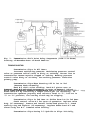
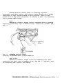
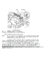
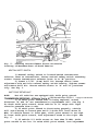
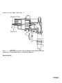
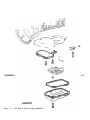
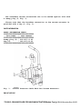
AUTO TRANS DIAGNOSIS - W4A020 & W4A040
Article Text
1994 Mercedes-Benz S320
For 1
Copyright © 1998 Mitchell Repair Information Company, LLC
Thursday, November 20, 2008 02:08PM
ARTICLE BEGINNING
AUTOMATIC TRANSMISSIONS
Mercedes-Benz W4A020 & W4A040
APPLICATION & IDENTIFICATION
Identification code is stamped on identification plate or
transmission housing. Use identification code when ordering parts.
TRANSMISSION APPLICATIONS
ÄÄÄÄÄÄÄÄÄÄÄÄÄÄÄÄÄÄÄÄÄÄÄÄÄÄÄÄÄÄÄÄÄÄÄÄÄÄÄÄÄÄÄÄÄ
Year/Vehicle
Application
Trans.
Model
1983
240D ..............................
300 Series ........................
380 Series ........................
W4A020
W4A040
W4A040
1984
240D ..............................
300 Series ........................
380 Series ........................
W4A020
W4A040
W4A040
1985
190
300
380
500
Series
Series
Series
Series
........................
........................
........................
........................
W4A020
W4A040
W4A040
W4A040
1986
190
300
380
500
Series
Series
Series
Series
........................
........................
........................
........................
W4A020
W4A040
W4A040
W4A040
1987
190
300
420
560
Series
Series
Series
Series
........................
........................
........................
........................
W4A020
W4A040
W4A040
W4A040
1988
190D (2.5L & 2.5L TD) .............
190E (2.3L,
2.3L-16V & 2.6L) .................
W4A020
W4A020
260E (2.6L) ........................
300E ..............................
300D ..............................
300SDL ............................
300TD .............................
420SEL ............................
560SEC ............................
560SEL ............................
560SL .............................
1989
190D (2.5L & 2.5L TD) .............
190E (2.3L,
2.3L-16V & 2.6L) .................
260E (2.6L) ........................
300E ..............................
300D ..............................
300SDL ............................
300TD .............................
420SEL ............................
560SEC ............................
560SEL ............................
560SL .............................
1990
190D (2.5L & 2.5L TD) .............
190E (2.3L,
2.3L-16V & 2.6L) .................
260E (2.6L) .......................
300E ..............................
300D ..............................
300SDL ............................
300TD .............................
420SEL ............................
560SEC ............................
560SEL ............................
560SL .............................
1991
190E (2.3L) ...............
190E (2.6L) ...............
300CE (3.0L) ..............
300D (2.5L Turbo) .........
300E (2.6L) ...............
300E & 300TE (3.0L) .......
300SE & 300SEL (3.0L) .....
350SD &
350SDL Turbo (3.5L) .....
722.408
722.409
722.359
722.418
722.409
722.358
722.351
W4A020
W4A040
W4A040
W4A040
W4A040
W4A040
W4A040
W4A040
W4A040
W4A020
W4A020
W4A020
W4A040
W4A040
W4A040
W4A040
W4A040
W4A040
W4A040
W4A040
W4A020
W4A020
W4A020
W4A040
W4A040
W4A040
W4A040
W4A040
W4A040
W4A040
W4A040
W4A020
W4A020
W4A040
W4A020
W4A020
W4A040
W4A040
722.361 W4A040AUTO TRANS DIAGNOSIS - W4A020 & W
420SEL (4.2L) .............
500SL (5.0L) ..............
560SEC & 560SEL (5.6L) ....
722.355 W4A040
722.353 W4A040
722.350 W4A040
1992
190E (2.3L) ...............
190E (2.6L) ...............
300CE (3.0L) ..............
300D (2.5L Turbo) .........
300E (2.6L) ...............
300E & 300TE (3.0L) .......
300SD Turbo (3.5L) ........
300SE & 300SEL (3.2L) .....
400E (4.2L) ...............
400SE (4.2L) ..............
500E (5.0L) ...............
500SEL (5.0L) .............
722.408
722.409
722.359
722.418
722.409
722.358
722.367
722.368
722.354
722.366
722.365
722.370
W4A020
W4A020
W4A040
W4A020
W4A020
W4A040
W4A040
W4A040
W4A040
W4A040
W4A040
W4A040
1993
190E (2.3L) ...............
190E (2.6L) ...............
300D (2.5L Turbo) .........
300E (2.8L) ...............
300E (3.2L) ...............
300SD (3.5L) ..............
400E (4.2L) ...............
400SEL (4.2L) .............
500E (5.0L) ...............
500SEL (5.0L) .............
722.408
722.409
722.418
722.433
722.369
722.367
722.354
722.366
722.365
722.370
W4A020
W4A020
W4A020
W4A020
W4A040
W4A040
W4A040
W4A040
W4A040
W4A040
1994
C220 (2.3L) ...............
C280 (2.8L) ...............
E320 (3.2L)
Cabriolet ...............
Coupe ...................
Sedan ...................
Wagon ...................
E420 (4.2L) ...............
E500 (5.0L) ...............
S350 (3.5L) ...............
S420 (4.2L) ...............
S500 (5.0L) ...............
722.423 W4A020
722.424 W4A020
722.369
722.369
722.369
722.369
722.366
722.370
722.367
722.366
722.370
W4A020
W4A020
W4A020
W4A020
W4A020
W4A040
W4A040
W4A040
W4A040
ÄÄÄÄÄÄÄÄÄÄÄÄÄÄÄÄÄÄÄÄÄÄÄÄÄÄÄÄÄÄÄÄÄÄÄÄÄÄÄÄÄÄÄÄÄ
DESCRIPTION
AUTO TRANS DIAGNOSIS - W4A020 & W
TRANSMISSION
This is a fully automatic 4-speed transmission consisting of
a 3-element welded torque converter, 2 compound planetary gear sets, 2
multiple-disc clutches, one overrunning clutch and 3 brake bands.
Brake bands control function of planetary gear sets. A hydraulic
system, pressurized by a primary gear type pump and a secondary piston
type pump provide working pressure required to operate friction
elements and automatic controls.
1st Gear
In 1st gear, brake band B-2 is applied and the one-way
converter clutch is locked. In selector lever position "2", clutch K-2
is also engaged. Both planetary gear sets are involved in gear
reduction.
2nd Gear
In 2nd gear, brake band B-1 and brake band B-2 are applied.
Both planetary gear sets are involved in gear reduction.
3rd Gear
In 3rd gear, brake band B-2 is applied and clutch K-1 is
engaged. Only the rear planetary gear set is involved in gear
reduction.
4th Gear
In 4th gear, clutch K-1 and clutch K-2 are applied. Both
planetary gear sets rotate as a locked unit.
Reverse Gear
In reverse, disc brake B-3 is applied, the one-way converter
clutch is locked, and clutch K-2 is engaged. Both planetary gear sets
are involved in gear reduction.
VALVE BODY
The valve body receives inputs from selector lever position,
mode selector switch, accelerator pedal position (control pressure),
engine torque (intake manifold vacuum), kick-down and vehicle speed.
Depending on operating conditions, the oil flow is controlled to
various points of demand in the transmission and the quality and
pressure level are adapted to requirements.
PRIMARY & SECONDARY PUMP
Primary Pump
The primary pump is housed in the front transmission cover
Mercedes-Benz
S320For 1
AUTOis
TRANS
DIAGNOSIS
W4A020through
& W4A040Article
Text (p.
4)1994of
and
driven
by the -engine
the drive
flange
the torque
Copyrig
converter. The primary pump operates as long as the engine is turning,
and supplies pressurized oil to the entire hydraulic system. The drive
of the secondary pump is switched off by the cut-off piston by means
of primary pump pressure.
Secondary Pump
The secondary pump is required only for towing and towstarting the vehicle. It is designed as an external gear pump and is
positioned in the rear section of the transmission. If needed, the
secondary pump is driven by the centrifugal governor shaft. The
secondary pump operates only if the engine is not running and the
vehicle is rolling (tow-starting procedure), while brake band B-2
slowly engages. Pump stops operating when vehicle comes to a stop or
if transmission has shifted into 4th gear (engine running).
OPERATING PRESSURES
The working pressure control valve, basic pressure control
valve, 2 two-way check balls, a modulating pressure relief valve, and
a non-return (one-way) valve and restriction form the working pressure
circuit. The working pressure circuit is influenced by position of
accelerator pedal, vehicle speed, selector lever position, and gear
engaged.
The working pressure, governed by working pressure circuit,
operates disc brake B-3, brake bands and clutches. The pressure level
is adapted to the particular operating condition, regardless of the
quantity of oil supplied from the primary pump or secondary pump. This
enables the primary pump capacity to be kept as low as possible and
achieve a high transmission efficiency.
The working pressure is always the highest pressure in the
hydraulic system. All other operating pressures are derived from this
maximum pressure and reduced by control valves to a lower pressure
level. The following governed pressures control the hydraulic system
and operate shift element.
*
*
*
*
*
*
*
*
*
*
Reduced Operating Pressure
Governor Pressure
Lubricating Pressure
Modulating Pressure (Vacuum Controlled)
Modulating Pressure (Governor Controlled)
Full Throttle Pressure
Load Dependent Control Pressure
Kick-Down Control Pressure
Boosted Governor Pressure
Shift Pressure
DAMPER SYSTEM
AUTO TRANS
The principal task of the hydraulic system (circuits)
consists of controlling the working pressure during gear changes
(shifts). During each gear shift transition, the engine speed
increases (during a downshift) or decreases (during an upshift). In
order to provide a smooth transition between gear shifts, 4
independent damper circuits are used.
The clutch K-1 damper circuit controls clutch K-1 during 2nd
to 3rd gear downshifts or upshifts. The clutch K-2 damper circuit
controls clutch K-2 during 3rd to 4th gear downshifts or upshifts. The
brake band B-1 damper circuit controls brake band B-1 during 1st to
2nd gear downshifts or upshifts.
The "engaging" damper circuit controls the engagement of the
clutches or brake bands, depending on selector lever position. When
selector lever is moved from "N" (Neutral) to "D" (Drive) or "3" (3rd
gear), brake bands B-1 and B-2 are controlled. When selector lever is
moved from "N" (Neutral) to "2" (2nd gear), clutch K-2 and brake band
B-2 are controlled. When selector lever is moved from "N" (Neutral) to
"R" (Reverse), clutch K-2 and disc brake B-3 are controlled.
The"engaging" damper controls the working pressure pattern after drive
positions "R", "D", "3" and "2" are engaged.
TRANSMISSION SHIFT POINT DELAY
The 2nd to 3rd gear upshift on some models is delayed 60-80
seconds to enable the catalytic converter to more rapidly reach its
operating temperature. The shift point retard solenoid is energized by
the CIS-E control unit or air mass sensor control unit through the
transmission shift point (upshift) retard relay.
Governor pressure is lowered through hydraulic line which is
bolted to the governor pressure test port. See Fig. 1. Under certain
operating conditions (coolant temperature, vehicle speed and time),
the solenoid valve is de-energized and the governor pressure is
dumped. The 2nd to 3rd gear upshift is delayed only when coolant
temperature is 0-140øF (0-60øC). The operating time is dependent on
coolant temperature when the engine is started, and is longest when
coolant temperature is 68-86øF (20-30øC).
AUTO TRANS DIAGNOSIS - W4A020 & W4A040Article Text (p. 6)1994 Mercedes-Benz S320For 1
Copyrig
Fig. 1: Transmission Shift Point Delay Components (190E 2.3L Shown)
Courtesy of Mercedes-Benz of North America.
TROUBLE SHOOTING
Transmission Slips In All Gears
Incorrect modulating pressure. Modulating pressure control
valve or pressure relief valve is dirty or sticking. Vacuum line to
transmission vacuum capsule clogged or leaking. Working pressure
control valve dirty or sticking. Low working pressure. Defective
primary pump.
Transmission Slips When Starting Off In 1st Or 2nd
(Reverse Works Normally)
Band B-2 shift valve sticking. Band B-2 piston worn or
damaged. Band B-2 adjusted incorrectly or worn or damaged. Adjust
1994 Mercedes-Benz S320For 1
AUTO TRANS
DIAGNOSIS
- W4A020 &a W4A040Article
Textpin
(p. 7)(if
brake
Band B-2
by installing
longer thrust
necessary). If
transmission operates properly with selector lever in "2", but not in
"3" or "D" position, the one-way clutch may be slipping.
Transmission Slips In 2nd Gear Or Shifts From 1st To 3rd Gear
Check control valve B-1 for ease of operation. Replace valve
body (if necessary). Remove and install brake band piston B-1, check
sealing ring and replace (if necessary). Replace brake band B-1 and
thrust body for B-1. Command valve binding.
Transmission Slips During 2-3 Upshift Or Slips Initially,
Copyrig
Then Grabs Hold
Check modulating pressure and adjust (if necessary). Check
for temperature throttle installation (if equipped). Valve body worn
or damaged. Replace valve body (if necessary). Replace inner plates of
clutch K-1 or recondition clutch (if necessary). Check Teflon ring of
front cover.
Transmission Slips During 3-4 Upshift
Check and adjust modulating pressure. Governor damaged or
working pressure incorrect. Valve body worn or damaged. Replace valve
body (if necessary) Check Teflon rings supporting clutch K-2. Replace
inner plates of clutch K-2 or recondition clutch (if necessary).
No Positive Engagement In Reverse
Check plates and sealing rings on disc brake B-3 piston.
Replace if necessary.
Harsh Engagement When Shifting Gears
Incorrect working pressure. Check and adjust modulating
pressure. Check vacuum line and connections for leaks. On diesel
engine equipped vehicles, check vacuum control valve. Coolant entering
transmission oil cooler and contamination transmission fluid. Replace
radiator. If necessary, replace all friction linings and/or replace
transmission.
Harsh Engagement When Selecting "D" Or "R"
Idle speed too high. Check pressure receiving (pick-up)
piston in valve body for ease of operation and correct installation.
Replace valve body (if necessary).
NOTE:
Pressure pick-up requires a running period of approximately
2 seconds. Harsh engagement may occur during repeated shifts
between "N" and "D". If harshness takes place within 2
seconds, condition is considered normal.
Harshness On 4-3 Downshift
Sealing ring on release end of band B-2 worn or damaged. Band
B-2 piston worn or damaged. Band B-2 thrust body damaged.
Chatter During Upshift
If upshift is not in proper order, repair or replace valve
body.
Will Not Upshift
Incorrect governor pressure. Defective governor assembly.
Check kickdown solenoid valve for a tendency to stick or for constant
voltage to solenoid caused by a defective fuel pump relay or sticking
AUTO TRANS
kickdown switch. Valve body dirty or valves sticking. Repair or
replace valve body.
Upshifts At Higher Speeds Than Specified
Check pressure control cable engagement, condition and
adjustment. Check kickdown solenoid valve for a tendency to stick or
for constant voltage to solenoid caused by a defective fuel pump relay
or sticking kickdown switch. Check governor pressure. If regulator
pressure is too low, replace centrifugal governor. Ensure control
pressure regulating valve is operable.
Upshifts At Lower Speeds Than Specified
Check pressure control cable engagement, condition and
adjustment. Check full throttle stop by accelerating engine and
ensuring that throttle valve rests against full throttle stop.
Readjust throttle stop (if necessary). Check governor pressure. If
governor pressure is too high, replace centrifugal governor. Repair or
replace valve body.
No Kickdown
Check throttle control and pressure control cable engagement,
condition and adjustment. Connect kickdown solenoid to battery and
check for proper operation. Replace solenoid (if necessary). Check
kickdown valve in valve body. Replace valve body (if necessary).
No Downshift (4-3 & 3-2)
Control pressure cable out of adjustment. Leaking vacuum
hoses and/or connections. Ensure brake shaft piston is operable.
Replace valve body (if necessary).
Uncontrolled Downshifts Outside Range Of Kickdown Switch
Remove kickdown solenoid valve. Check "O" ring on kickdown
solenoid valve for damage. Check kickdown switch for sticking in
pushed-in position. Replace switch (if necessary). Check for kickdown
solenoid valve stuck in opened position. Replace kickdown solenoid
valve (if necessary).
Poor Acceleration When Starting Off
Check stall speed. If stall speed is 400-700 RPM less than
specified value, one-way clutch in torque converter is slipping.
Replace torque converter (if necessary).
Parking Lock Will Not Engage
Check rear engine mount. Replace engine mount (if necessary).
Check adjustment of selector rod. Adjust selector rod (if necessary).
Selector Lever Cannot Engage "R" Or "P"
With engine running, clean centrifugal governor and ensure
correct operation. With engine not running, check operation of detent
AUTO TRANS DIA
piston in lower cover.
Engine Cannot Be Started In Selector Lever Position "P" & "N"
Adjust shift rod and starter lock-out switch. Replace starter
lock-out switch (if necessary).
Oil Loss With Smoke In Exhaust
Diaphragm in vacuum control unit defective. Transmission oil
is being drawn from engine through vacuum line. Replace vacuum control
unit (if necessary).
Oil Loss Between Torque Converter & Primary Pump
Seal torque converter oil drain plug. If leak continues,
replace radial sealing ring and "O" ring on primary pump. Check
primary pump "O" ring groove for porosity. Replace primary pump (if
necessary).
Howling Noise When Changing Gears (Under Full Load)
Replace transmission oil filter.
Howling Noise Which Increases As Engine RPM Increases
Check primary pump and replace if necessary.
1st Gear & Reverse Too Loud
Replace front planetary gear set. Reverse and 1st gear are
louder than forward (driving) gears due to gear reduction. If noise
seems too loud, or if in doubt, a similar vehicle should be used for
comparison.
3rd Gear Too Loud
Replace rear planetary gear set.
Rattling Noise at 1500 RPM In All Selector Lever Positions
Except "R"
Disc brake B-3 plates are vibrating in transmission housing.
Replace plates of disc brake B-3, install damper spring and set
release clearance to minimum value.
Light Grinding Noise In "P" & "N" Selector Lever Positions
This condition is normal if a "rolling" noise of front
planetary gear set is heard. If noise seems too loud, or if in doubt,
a similar vehicle should be used for comparison.
"Rolling" Noises When Driving In Reverse
Disc brake B-3 release clearance too great. Adjust release
clearance to 0.06-0.08" (1.5-2.0 mm) or replace disc brake plates.
Outside plate carrier of clutch K-1 contacts piston.
AUTO TR
Primary Pump Bushing Loosens After A Short Operating Period
Dowel pins for centering transmission to engine are not in
place.
TESTING
For vacuum control circuit tests, hydraulic pressure tests,
and road tests, see the AUTO TRANS OVERHAUL - W4A020 & W4A040 article
in the AUTO TRANS OVERHAUL section.
END OF ARTICLE
AUTO TRANS DIAGNOSIS - W4A020 & W4A040Article Text (p. 11)1994 Mercedes-Benz S320For 1
Copy
TRANSMISSION REMOVAL & INSTALLATION - A/T
Article Text
1994 Mercedes-Benz S320
For 1
Copyright © 1998 Mitchell Repair Information Company, LLC
Thursday, November 20, 2008 02:11PM
ARTICLE BEGINNING
1994 TRANSMISSION SERVICING
Mercedes-Benz Transmission Removal & Installation - Automatic
S320, S350, S420, S500
REMOVAL & INSTALLATION
CAUTION: If metal chips are present in transmission oil pan, torque
converter must be replaced. Flushing will not remove all
metal chips from a torque converter. Failure to replace
torque converter may result in future transmission failure.
S350, S420 & S500
Removal
1) Disconnect negative battery cable. Disconnect longitudinal
engine throttle control shaft. Disconnect control pressure cable.
Remove front crossmember assembly.
2) Remove transmission oil pan drain plug. Remove torque
converter drain plug. Drain transmission fluid. Remove starter. Remove
torque converter drive plate bolts (6 bolts) through starter opening.
Remove entire exhaust system assembly from exhaust manifold(s). Remove
rear crossmember with mount.
3) Release cable strap and unscrew cable on kickdown solenoid
valve. Unscrew retaining bolts for pulse generator. Remove pulse
generator. On V8 engines, disconnect shift point retard connector
located on right rear corner of engine.
4) On all models, loosen drive shaft center bearing bolts.
Loosen large clamping nut on drive shaft. Clamping nut is located near
center bearing. Remove drive shaft flange bolts. With clamping nut
loosened, push drive shaft as far back from transmission as possible.
5) Turn starter lockout switch locking element before
disconnecting starter lockout switch connector. Using 2 screwdrivers,
pry off starter lockout switch connector from transmission.
6) Disconnect shift rod from range selector lever. Disconnect
White vacuum line for vacuum box. Disconnect Red vacuum line for mode
program. Disconnect Black/Green vacuum line for shift point retard.
7) Disconnect transmission oil cooler feed and return lines.
Remove transmission dipstick tube bolt from transmission and cylinder
head. Remove transmission dipstick tube.
8) On V8 engines, remove transmission mounting bolts except 2
nuts on either side of transmission. Using a transmission jack, lift
transmission slightly. Remove 2 remaining transmission mounting nuts.
9) On 6-cylinder engines, remove transmission mounting bolts
except 2 bolts on either side of transmission. Using a transmission
jack, lift transmission slightly. Remove 2 remaining transmission
mounting bolts. On all vehicles, push transmission rearward and lower.
Ensure torque converter does not fall from transmission during
removal.
Installation
To install, reverse removal procedure. Tighten bolts and nuts
to specification. See TORQUE SPECIFICATIONS. Use NEW transmission oil
cooler feed and return line "O" rings. Adjust control pressure cable
and linkages as necessary. Fill transmission with fluid. See
TRANSMISSION SERVICING - A/T article in AUTOMATIC TRANSMISSION
SERVICING section.
S320
Removal
1) Disconnect negative battery cable. Remove transmission
dipstick tube bolt from transmission and cylinder head. Using pliers,
squeeze plastic clip together and pull out control pressure cable.
2) Remove transmission oil pan drain plug. Remove torque
converter drain plug. Drain transmission fluid. Remove plastic cover
to access torque converter drive plate bolts. Remove torque converter
drive plate bolts (6 bolts) through opening.
3) Remove crossmember with mount. Remove drive shaft flange
bolts. Disconnect oxygen sensor harness on tunnel and disconnect
mounting clips. Remove exhaust support bracket bolts from
transmission. Remove entire exhaust system assembly from exhaust
manifold.
4) Remove speedometer shaft. On vehicles equipped with an
electronic speedometer, unscrew pulse generator. On all vehicles,
disconnect shift point increase solenoid valve connector. Disconnect
transmission overload switch connector and pull off vacuum line.
5) Turn starter lockout switch locking element before
disconnecting starter lockout switch connector. Using 2 screwdrivers,
pry off starter lockout switch connector from transmission.
6) Disconnect shift rod from range selector lever. Disconnect
transmission oil cooler feed and return lines. Remove transmission
dipstick tube bolt from transmission. Remove transmission dipstick
tube. Ensure all electrical connections are disconnected from
transmission.
7) Install Retainer (126 589 01 62 00) through ventilation
grill cutout into torque converter drain plug. Remove transmission
mounting bolts except 2 bolts on either side of transmission. Using a
transmission jack, lift transmission slightly. Remove 2 remaining
transmission mounting bolts. Push transmission rearward and lower.
Installation
TRANSMISS
To install, reverse removal procedure. When installing torque
converter to transmission, apply a light coat of grease to torque
converter centering pin. Tighten bolts and nuts to specification. See
TORQUE SPECIFICATIONS. Adjust control pressure cable and linkages as
necessary. Fill transmission with fluid. See appropriate
TRANSMISSION SERVICING - A/T article in AUTOMATIC TRANSMISSION
SERVICING section.
TORQUE SPECIFICATIONS
TORQUE SPECIFICATIONS TABLE
ÄÄÄÄÄÄÄÄÄÄÄÄÄÄÄÄÄÄÄÄÄÄÄÄÄÄÄÄÄÄÄÄÄÄÄÄÄÄÄÄÄÄÄÄÄÄÄÄÄÄÄÄÄÄÄÄÄÄÄÄ
Application
Ft. Lbs. (N.m)
Drive Plate Bolt .................................
Front Crossmember Bolt (1) .......................
Drive Shaft Clamping Nut ................... 22-30
Transmission Mounting Bolt (2)
10-mm ..........................................
12-mm ..........................................
Transmission Oil Pan Drain Plug ..................
Torque Converter Drain Bolt ......................
31 (42)
33 (45)
(30-40)
41
48
10
12
(55)
(65)
(14)
(16)
(1) - Replace self-locking bolts.
(2) - V8 engines use 2 nuts, one on each side of
transmission.
ÄÄÄÄÄÄÄÄÄÄÄÄÄÄÄÄÄÄÄÄÄÄÄÄÄÄÄÄÄÄÄÄÄÄÄÄÄÄÄÄÄÄÄÄÄÄÄÄÄÄÄÄÄÄÄÄÄÄÄÄ
END OF ARTICLE
TRANSM
TRANSMISSION SERVICING - A/T
Article Text
1994 Mercedes-Benz S320
For 1
Copyright © 1998 Mitchell Repair Information Company, LLC
Thursday, November 20, 2008 02:12PM
ARTICLE BEGINNING
1994 TRANSMISSION SERVICING
Mercedes-Benz Transmission Servicing - Automatic
S320, S350, S420, S500
IDENTIFICATION
AUTOMATIC TRANSMISSION APPLICATIONS TABLE
ÄÄÄÄÄÄÄÄÄÄÄÄÄÄÄÄÄÄÄÄÄÄÄÄÄÄÄÄÄÄÄÄÄÄÄÄÄÄÄÄÄÄÄÄÄÄÄÄÄÄÄÄÄÄÄÄÄÄÄÄÄÄÄÄÄÄÄÄÄÄ
Model
S320
S350
S420
S500
Body
3.2L
3.5L
4.2L
5.0L
...................
...................
...................
...................
140.032
140.043
140.043
140.051
Transmission
....................
....................
....................
....................
722.508
722.367
722.366
722.370
ÄÄÄÄÄÄÄÄÄÄÄÄÄÄÄÄÄÄÄÄÄÄÄÄÄÄÄÄÄÄÄÄÄÄÄÄÄÄÄÄÄÄÄÄÄÄÄÄÄÄÄÄÄÄÄÄÄÄÄÄÄÄÄÄÄÄÄÄÄÄ
LUBRICATION
SERVICE INTERVALS
Check fluid level at first 800-1000 miles and every 15,000
miles afterward. Change fluid and filter every 30,000 miles. Under
severe service conditions, change fluid every 15,000 miles.
CHECKING FLUID LEVEL
With transmission fluid at normal operating temperature of
176øF (80øC), park vehicle on level surface. Place selector lever in
the "P" position and set parking brake. Allow engine to idle for 2
minutes. Measure fluid level with dipstick completely inserted and
locking lever released.
RECOMMENDED FLUID
Use Dexron-II ATF.
FLUID CAPACITIES
TRANSMISSION REFILL CAPACITIES TABLE
ÄÄÄÄÄÄÄÄÄÄÄÄÄÄÄÄÄÄÄÄÄÄÄÄÄÄÄÄÄÄÄÄÄÄÄÄÄÄÄÄÄÄÄÄÄÄÄÄÄÄÄÄÄÄÄÄÄÄÄÄÄÄÄÄÄÄÄÄÄÄ
Refill
Qts. (L)
Application
S320 & S350
................
6.6 (6.2)
Dry Fill
Qts. (L)
.................
7.7 (7.3)
S420 & S500
................
8.1 (7.7)
.................
9.1 (8.6)
ÄÄÄÄÄÄÄÄÄÄÄÄÄÄÄÄÄÄÄÄÄÄÄÄÄÄÄÄÄÄÄÄÄÄÄÄÄÄÄÄÄÄÄÄÄÄÄÄÄÄÄÄÄÄÄÄÄÄÄÄÄÄÄÄÄÄÄÄÄÄ
DRAINING & REFILLING
1) Disconnect filler tube from oil pan, and drain fluid.
Rotate engine until torque converter drain plug is at bottom of torque
converter housing. Remove plug and drain fluid. Install plug, using a
new sealing ring. Remove oil pan and filter.
2) Install filter and oil pan, using a new gasket. Attach
fill tube, using new sealing rings on hollow screw. Add about 3.2 qts.
(3L) of automatic transmission fluid.
3) Apply parking brake and start engine. Place selector lever
in the "P" position. Run engine at idle and gradually add fluid.
Momentarily place selector lever in each gear, and then return to "P"
position. Check fluid level and add if necessary. DO NOT overfill.
ADJUSTMENTS
SHIFT LINKAGE
Before adjusting shift linkage, make sure neutral safety
switch is properly adjusted. See NEUTRAL SAFETY SWITCH. To adjust
shift linkage, disconnect control rod from gear selector lever. Place
transmission lever in "N" (Neutral) position. Loosen lock nut at end
of control rod. Adjust rod length so clearance is .04" (1 mm) between
gear selector lever and "N" stop on gate plate. Connect control rod,
and secure and tighten lock nut. See Fig. 1.
Fig. 1: Adjusting Shift Linkage (722.4 Trans. Shown; Others Similar)
Courtesy of Mercedes-Benz of North America
CONTROL PRESSURE CABLE
S350
TRANSM
Ensure throttle control cable is correctly adjusted.
Disconnect cable ball socket. Pull control cable forward until slight
resistance is felt. Holding cable in this position, check if ball
socket fits on ball with no tension. If tension is felt, use adjusting
nut to change cable length.
S320
Remove air cleaner. Adjust control pressure cable by turning
adjusting screw until tips of needles align. Install air cleaner. See
Fig. 2.
Fig. 2: Aligning Needles (S320)
Courtesy of Mercedes-Benz of North America
S420 & S500
Remove air cleaner. Loosen 2 nuts on connecting rod. Turn
connecting rod until tips of needles align. See Fig. 3. Tighten 2 nuts
on connecting rod. Install air cleaner.
TRANSMISSION SERVICING - A/TArticle Text (p. 3)1994 Mercedes-Benz S320For 1
Co
Fig. 3: Aligning Needles (V8 Engine)
Courtesy of Mercedes-Benz of North America
CONTROL PRESSURE CABLE VACUUM ELEMENT
NOTE:
Not all vehicles are equipped with a control pressure cable
vacuum element. Only vehicles with dual shifting modes for
transmission may have this option.
1) Ensure control pressure cable is properly adjusted. See
CONTROL PRESSURE CABLE. Raise and support vehicle. Disconnect vacuum
hose from control pressure cable vacuum element. See Fig. 4.
2) Connect a vacuum supply to vacuum element. Pull control
pressure cable up to full load stop. Measure how far piston sticks out
of vacuum element (distance "A"). See Fig. 5. See VACUUM ELEMENT
PISTON PROTRUSION table. If vacuum element piston protrusion is not to
© 1998 Mitchell R
Mercedes-Benz
S320For
1 Copyright
TRANSMISSION
SERVICING
- A/TArticlescrew
Text (p.on
4)1994
specification,
turn adjustment
control
pressure
cable
vacuum
element. See Fig. 4.
Fig. 4: Connecting Vac. Hose To Control Pressure Cable Vac. Element
Courtesy of Mercedes-Benz of North America
VACUUM ELEMENT PISTON PROTRUSION TABLE
ÄÄÄÄÄÄÄÄÄÄÄÄÄÄÄÄÄÄÄÄÄÄÄÄÄÄÄÄÄÄÄÄÄÄÄÄÄÄÄÄÄÄÄÄÄÄÄÄÄÄÄÄÄÄÄÄÄÄÄÄÄÄÄÄÄÄÄÄÄÄ
Application
6-Cyl.
With
With
8-Cyl.
Engine
722.3 Transmission (1) ..............................
722.4 Transmission (1) ..............................
Engine ..............................................
In. (mm)
.28 (7)
.24 (6)
.24 (6)
(1) - See IDENTIFICATION for transmission application.
ÄÄÄÄÄÄÄÄÄÄÄÄÄÄÄÄÄÄÄÄÄÄÄÄÄÄÄÄÄÄÄÄÄÄÄÄÄÄÄÄÄÄÄÄÄÄÄÄÄÄÄÄÄÄÄÄÄÄÄÄÄÄÄÄÄÄÄÄÄÄ
TRANSMISSION SERVICING - A/TArticle Text (p. 5)1994 Mercedes-Benz S320For 1
Copyright © 1998 Mitchell R
Fig. 5: Checking Vacuum Element Piston Protrusion
Courtesy of Mercedes-Benz of North America
NEUTRAL SAFETY SWITCH
1) Neutral safety switch is located behind transmission
selector lever on transmission. Loosen neutral safety switch attaching
screws. Ensure transmission selector lever is in "N" position.
2) Insert a 5/32" (4 mm) drill bit through select lever
adjustment hole and into neutral safety switch housing. Tighten screws
and remove drill bit. Ensure vehicle starts in "P" and "N" positions
only. See Fig. 1.
SHIFT POINT RETARD UNIT
NOTE:
Not all vehicles are equipped with shift point retard.
TRANSMISSION SERVICING - A/TArticle Text (p. 6)1994 Mercedes-Benz S320For 1
Copyright © 1998 Mitchell R
1) If shift point retard unit is being replaced, ensure
distances "A" and "B" are transferred to replacement unit. See Fig. 6.
To check shift point retard, drive vehicle in "D" range with light
throttle pressure from a stop.
2) If shift point retard is functioning properly, vehicle
will start moving in second gear and 2-3 shift will occur above 30
MPH. If vehicle starts in first gear, shift point retard is too high.
To lower shift point retard, turn adjustment screw to the right. See
Fig. 6.
3) If vehicle 2-3 shift occurs at less than 30 MPH, shift
point retard is too low. To raise shift point retard, turn adjustment
screw to the left. See Fig. 6.
Fig. 6: Identifying Shift Point Retard Adjustment Screw
Courtesy of Mercedes-Benz of North America
END OF ARTICLE
TRANSM
FIXTURE FOR B-1 PISTON R & I - AUTO TRANS.722.3/4/5
Article Text
1994 Mercedes-Benz S320
For 1
Copyright © 1998 Mitchell Repair Information Company, LLC
Thursday, November 20, 2008 02:13PM
ARTICLE BEGINNING
TECHNICAL SERVICE BULLETIN
AUTOMATIC TRANSMISSIONS 722.3/4/5
FIXTURE FOR B-1 PISTON REMOVAL AND INSTALLATION
Model(s):
Group:
Bulletin No.:
Date:
All Mercedes-Benz Models With Auto. Trans. 722.3/4/5
27 - Automatic Transmission
MBNA 27/31, 58/84
August 1995
SERVICE INFORMATION
A new special tool has been developed for the removal and
installation of automatic transmission piston B-1 with the
transmission installed in the vehicle.
SPECIAL TOOL INFORMATION TABLE
ÄÄÄÄÄÄÄÄÄÄÄÄÄÄÄÄÄÂÄÄÄÄÄÄÄÄÄÄÄÄÄÄÄÄÄÄÄÄÄÄÄÄÄÄÄÄÄÄÄÄÂÄÄÄÄÄÄÄÄÄÄÄÄÄÄÄÄ
Part Number
Description
³
³ Group/Category
ÄÄÄÄÄÄÄÄÄÄÄÄÄÄÄÄÄÅÄÄÄÄÄÄÄÄÄÄÄÄÄÄÄÄÄÄÄÄÄÄÄÄÄÄÄÄÄÄÄÄÅÄÄÄÄÄÄÄÄÄÄÄÄÄÄÄÄ
900 589 27 23 00 ³ Fixture for B-1 piston removal ³ 27/B
³ and installation See Fig. 1. ³
ÄÄÄÄÄÄÄÄÄÄÄÄÄÄÄÄÄÁÄÄÄÄÄÄÄÄÄÄÄÄÄÄÄÄÄÄÄÄÄÄÄÄÄÄÄÄÄÄÄÄÁÄÄÄÄÄÄÄÄÄÄÄÄÄÄÄÄ
WORK INSTRUCTIONS FOR USE OF B-1 PISTON SPECIAL TOOL
1. Remove transmission oil pan and gasket, oil filter, valve body and
large intermediate plate. See Fig. 2. (SMS Job Nos. 27-400 and
27-430).
2. Loosen closing cover of reaction valve B-1 (33) or overload
protection switch S65 (33b) by approx. 3 - 4 turns. See Fig. 3.
* Tightening torque:
70 N.m.
3. Install special tool angled bracket to transmission housing using
three 8 mm hex bolts. See Fig. 4.
* Tightening torque:
13 N.m.
4. Mount special tool compressing lever to angled bracket at side
mounting eyelet that serves as pivot point. See Fig. 5.
5. Pull special tool compressing lever outward, in direction of
lower arrow to press in cover of piston B-1 allowing removal of
circlip. See Fig. 6.
6. Carefully release compressing lever inward, in direction of lower
arrow to remove piston B-1 from transmission housing. See Fig. 7.
7. Reassemble in reverse order.
CAUTION:
NOTE:
Fig. 1:
During reassembly, always observe critical attention to
correct installation position of B-1 piston return springs
and alignment of B-1 piston pin into band 1 socket.
An administrative message will be issued in the near future
regarding time allowance.
B-1 Piston Removal Fixture
FIXTURE FOR B
FIXTURE FOR B-1 PISTON R & I - AUTO TRANS.722.3/4/5Article Text (p. 3)1994 Mercedes-Benz S320F
Fig. 2:
Oil Pan & Valve Body Removal
Fig. 3:
Reaction Valve & Overload Protection Switch
Fig. 4:
Installing Angled Bracket
FIXTURE FOR B-1 PISTON R & I - AUTO TRANS.722.3/4/5Article Text (p. 4)1994 Mercedes-Benz S320F
Fig. 5:
Mounting Compressing Lever
FIXTURE FOR B-1 PISTON R & I - AUTO TRANS.722.3/4/5Article Text (p. 5)1994 Mercedes-Benz S320F
Fig. 6:
Compressing B-1 Piston Cover
Fig. 7:
Removing B-1 Piston
END OF ARTICLE
FIXTURE FOR B-1 PISTON R & I - AUTO TRANS.722.3/4/5Article Text (p. 6)1994 Mercedes-Benz S320F
722.3/4/5 - SEALING PLUGS FOR VACUUM ACTUATORS
Article Text
1994 Mercedes-Benz S320
For 1
Copyright © 1998 Mitchell Repair Information Company, LLC
Thursday, November 20, 2008 02:18PM
ARTICLE BEGINNING
TECHNICAL SERVICE BULLETIN
ALL MODELS WITH AUTOMATIC TRANSMISSION 722.3/4/5
SEALING PLUGS FOR VACUUM ACTUATORS
Model(s):
Group:
Bulletin No.:
Date:
1981
1981-83
1981-85
1982-83
1982-85
1984-85
1984-98
1984-93
1986-87
1986-89
1986-91
1986-93
1987
1987-89
1988-91
1988-93
1990-91
1990-93
Mercedes-Benz
Mercedes-Benz
Mercedes-Benz
Mercedes-Benz
Mercedes-Benz
Mercedes-Benz
Mercedes-Benz
Mercedes-Benz
Mercedes-Benz
Mercedes-Benz
Mercedes-Benz
Mercedes-Benz
Mercedes-Benz
Mercedes-Benz
Mercedes-Benz
Mercedes-Benz
Mercedes-Benz
Mercedes-Benz
380 SLC
380 SEL
300 TD, 300 SD, 380 SL
380 SEC
300 D, 300 CD
380 SE, 500 SEC, 500 SEL
190 D
190 E
300 SDL
560 SL
420 SEL, 560 SEC, 560 SEL
300 E
300 D, 300 TD
260 E
300 SEL
300 CE, 300 SE, 300 TE
350 SD, 350 SDL
300 D, 300 E 4MATIC,
300 TE 4MATIC, 300 SL, 500 SL
1992
Mercedes-Benz 400 SE
1992-93 Mercedes-Benz 300 SD, 400 E, 500 E, 500 SEL,
600 SEL
1993
Mercedes-Benz 400 SEL, 500 SEC, 600 SEC, 600 SL
1994-on Mercedes-Benz E 320, E 420, E 500, SL 320,
SL 500, SL 600. S 320, S 350,
S420, S 500, S 600, C 220, C 280
27 - Automatic Transmission
27/94
October 1993
SERVICE INFORMATION
To reduce the number of transmission variants, automatic
transmissions will be equipped in the future with a control pressure
cable of a standardized design that has two vacuum actuators.
The control pressure cable with two vacuum actuators in the plastic
housing is also used for transmissions which do not need either or
both of these vacuum actuators.
The redundant vacuum connections are to be sealed against dirt with
a dummy plug (5, Fig. 1).
Please note that the breather connection on the vacuum actuator is
provided with a cap (6, Fig. 1).
PARTS INFORMATION
PARTS INFORMATION TABLE
ÄÄÄÄÄÄÄÄÄÄÄÄÄÄÄÂÄÄÄÄÄÄÄÄÄÄÄÄÄÄÄ
Part Name
³ Part Number
ÄÄÄÄÄÄÄÄÄÄÄÄÄÄÄÅÄÄÄÄÄÄÄÄÄÄÄÄÄÄÄ
Dummy plug (5) ³ 000 987 11 45
Cap (6)
³ 140 997 00 20
ÄÄÄÄÄÄÄÄÄÄÄÄÄÄÄÁÄÄÄÄÄÄÄÄÄÄÄÄÄÄÄ
Fig. 1:
Control Pressure Cable With Two Vacuum Actuators
END OF ARTICLE
722.3/4/5 - SEALING PLUGS FOR VACUUM ACTUATORSArticle Text (p. 2)1994 Mercedes-Benz S320Fo
HAND-HELD TESTER MODULE UPDATES - NEW 4 MBYTE MODULE
Article Text
1994 Mercedes-Benz S320
For 1
Copyright © 1998 Mitchell Repair Information Company, LLC
Thursday, November 20, 2008 02:28PM
ARTICLE BEGINNING
TECHNICAL SERVICE BULLETIN
A. HAND-HELD TESTER (HHT) MODULE PLANNING OVERVIEW
B. INTRODUCTION OF 4 MBYTE MODULE
Model(s):
1986-93
1987
1987-89
1987-93
1990-93
Mercedes-Benz
Mercedes-Benz
Mercedes-Benz
Mercedes-Benz
Mercedes-Benz
1992
Mercedes-Benz
1992-93 Mercedes-Benz
1993
Mercedes-Benz
1994
Mercedes-Benz
1994-on Mercedes-Benz
Group:
Bulletin No.:
Date:
NOTE:
300 E
300 D, 300 TD
260 E
300 CE, 300 TE
300 D, 300 SL, 500 SL
300 E 4MATIC, 300 TE 4MATIC
400 SE
400 E, 500 E, 300 SD, 300 SE,
500 SEL, 600 SEL
400 SEL, 500 SEC, 600 SEC, 600 SL
E 500
E 320, E 420, SL 320, SL 500,
SL 600, S 320, S 350, S 420,
S 500, S 600, C 220, C 280
E 300, C 36
1995-on Mercedes-Benz
58 - Special Tools
99 - Service Literature
58/69B, 99/154B
January 1995
This bulletin supersedes Service Information No. MBNA 58/69A,
99/154A, dated June 1994.
A. HAND-HELD TESTER (HHT) MODULE PLANNING OVERVIEW
Periodic updates to HHT Modules and the introduction of new HHT
Modules ensure that the dealer technician is provided with the very
latest diagnostic information concurrent to production changes and the
introduction of new modules. Therefore, it is very important to use
the latest HHT Module available when performing diagnosis. The
following table provides an overview of HHT Module planning.
MODULE PLANNING OVERVIEW
ÄÄÄÄÄÄÂÄÄÄÄÄÄÄÄÄÄÄÄÄÂÄÄÄÄÄÄÄÄÄÄÄÄÄÄÄÄÄÄÄÄÄÄÄÄÄÄÄÄÄÄÄÄÄÄÄÄÄÄÄÄÄÄÄÄÄÄÄÄÄ
Issue ³
Model
Comments
³
³ Application ³
ÄÄÄÄÄÄÅÄÄÄÄÄÄÄÄÄÄÄÄÄÅÄÄÄÄÄÄÄÄÄÄÄÄÄÄÄÄÄÄÄÄÄÄÄÄÄÄÄÄÄÄÄÄÄÄÄÄÄÄÄÄÄÄÄÄÄÄÄÄÄ
1/94 ³ 124, 129
³ Obsolete (replaced by 12/94 issue, see below).
ÄÄÄÄÄÄÅÄÄÄÄÄÄÄÄÄÄÄÄÄÅÄÄÄÄÄÄÄÄÄÄÄÄÄÄÄÄÄÄÄÄÄÄÄÄÄÄÄÄÄÄÄÄÄÄÄÄÄÄÄÄÄÄÄÄÄÄÄÄÄ
3/94 ³ 140
³ Obsolete (replaced by 12/94 issue, see below).
ÄÄÄÄÄÄÅÄÄÄÄÄÄÄÄÄÄÄÄÄÅÄÄÄÄÄÄÄÄÄÄÄÄÄÄÄÄÄÄÄÄÄÄÄÄÄÄÄÄÄÄÄÄÄÄÄÄÄÄÄÄÄÄÄÄÄÄÄÄÄ
6/94 ³ 202
³ Obsolete (replaced by 12/94 issue, see below).
ÄÄÄÄÄÄÅÄÄÄÄÄÄÄÄÄÄÄÄÄÅÄÄÄÄÄÄÄÄÄÄÄÄÄÄÄÄÄÄÄÄÄÄÄÄÄÄÄÄÄÄÄÄÄÄÄÄÄÄÄÄÄÄÄÄÄÄÄÄÄ
12/94 ³ 124, 129,
³ New issue
³ 140, 202
³ (replacement for 1/94, 3/94, 6/94 issues).
ÄÄÄÄÄÄÁÄÄÄÄÄÄÄÄÄÄÄÄÄÁÄÄÄÄÄÄÄÄÄÄÄÄÄÄÄÄÄÄÄÄÄÄÄÄÄÄÄÄÄÄÄÄÄÄÄÄÄÄÄÄÄÄÄÄÄÄÄÄÄ
IMPORTANT NOTE:
Obsolete module 1/94, 3/94 and 6/94 are NOT to be
returned at this time. Please store these modules
with the new module in the HHT carrying case. Do not
discard these obsolete modules as you will forfeit
their core charge ($ 400.00 ea.)! Dealer will be
informed as to handling procedures regarding these
modules in the future.
For further details regarding the HHT Module Program Update Service,
please refer to S.I. MBNA 58/77A, 99/162A. January 1995.
B. INTRODUCTION OF 4 MBYTE MODULE
The release of the 12/94 HHT module marks the introduction of a 4
MByte module which provides diagnostic coverage for all models
including models 124, 129, 140 and 202. The integration of the three
previously valid modules into one module will allow the user to
quickly determine the status of modules on hand and will allow for
easier updating, currently planned to take place approx. 4 times per
year.
The past, often confusing practice of including updated diagnostic
information for a particular model on a module labeled for use only
with a different model should no longer occur.
The timeliness of future module updates is also scheduled for
improvement with the decision to perform the update service locally at
the Customer Assistance Center (CAC) in Montvale. New Jersey. Further
details regarding revisions to the update service will be released at
the modules next update.
END OF ARTICLE
HAND-HE


![Subject: [MB] 1987 W126 intermittent climate control](http://vs1.manualzilla.com/store/data/006030956_1-f014f75cb14526db0f9eb72ec9889b7e-150x150.png)