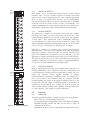
1
DSA250i & DSA230i LOUDSPEAKER
O W N E R ’S M A N U A L
DSAi Series Owner’s Manual
Congratulations on the purchase of your new EAW loudspeaker. You now own
one of the finest professional audio products available - the result of
exceptional engineering and meticulous craftsmanship. Please read these
instructions to get the maximum performance from your new loudspeaker.
SAFETY PRECAUTIONS - READ THIS FIRST
SAFETY INSTRUCTIONS
Read and heed all warnings and safety instructions in the accompanying "EAW
Loudspeaker Manual" before using this product. Failure to follow this precaution
may result in equipment damage, personal injury, or death.
WARNING: The loudspeaker is supplied with an ac mains power cable. Depending on
the voltage model ordered, this cable is configured with the most common ac mains
connector for that voltage. If the connector is not compatible with the local ac mains
receptacle, employ a licensed electrician to re-configure the cable with the proper
connector. Ensure that ac power supply has a properly grounded safety ground.
Failure to follow this warning could cause equipment damage, injury, or death.
CONSIGNES DE SÉCURITÉ - À LIRE EN PREMIER
INSTRUCTIONS RELATIVES À LA SÉCURITÉ
Lisez et respectez toutes les consignes de sécurité et les mises en garde fournies
dans le manuel des enceintes EAW avant d'utiliser ce produit. Le non-respect de
ces consignes et mises en garde peut entraîner des dommages aux équipements
et des accidents aux personnes pouvant être fatals.
ATTENTION: L'enceinte est fournie avec un cordon secteur. Selon la tension du
modèle commandé, ce câble est fourni avec la fiche la plus communément utilisée
avec cette tension. Si la fiche n'est pas compatible avec les prises secteur de votre
région, faites appel à un électricien agréé pour modifier le cordon secteur en fonction du format local. Vérifiez que la fiche secteur dispose d'une mise à la terre. Le
non-respect de la mise à la terre peut entraîner des dommages aux équipements et
des accidents aux personnes pouvant être fatals.
PRECAUZIONI DI SICUREZZA - DA LEGGERE PER PRIMO
NORME DI SICUREZZA
Prima di procedere con l'utilizzo del prodotto, leggere e rispettare ogni
avvertenza e norma di sicurezza riportata nel "Manuale EAW Loudspeaker". Il
mancato rispetto di ogni precauzione può causare danni all'apparecchiatura,
nonché infortuni alle persone o la morte.
i
ATTENZIONE: Il diffusore è completo di cavo d'alimentazione ac fornito in
dotazione. In base la voltaggio del modello di diffusore acquistato, il cavo è configurato con il connettore ac più adeguato. Nel caso in cui il connettore non sia compatibile con le prese di corrente adottate nell'area d'impiego, rivolgersi ad un elettricista qualificato per ri-configurare il cavo con il connettore più appropriato.
Assicurarsi che la presa di corrente sia adeguatamente collegata a terra. Il mancato
rispetto di tali norme può causare danni all'apparecchiatura, nonché infortuni alle
persone o la morte.
PRECAUCIONES DE SEGURIDAD - LEA ESTO PRIMERO
INSTRUCCIONES DE SEGURIDAD
Lea y observe todos los avisos e instrucciones de seguridad que aparecen en el
"Manual de altavoces EAW" adjunto antes de usar este aparato. El no observar
esta precaución puede dar lugar a averías en el aparato, daños en las personas o
incluso la muerte.
PRECAUCION: El altavoz viene de fábrica con un cable de corriente. Dependiendo
del voltaje que use el modelo solicitado, este cable estará configurado con el enchufe
más habitual para ese tipo de corriente. Si ese enchufe no es compatible con su salida de corriente, contacte con un electricista profesional para que cambie el enchufe
del cable por el tipo adecuado. Asegúrese de que la salida de corriente tenga una
conexión a tierra adecuada. El no observar esta advertencia puede dar lugar a
averías en el aparato, daños en las personas o incluso la muerte.
SICHERHEITSHINWEISE - LESEN SIE DIESEN ABSCHNITT ZUERST
SICHERHEITSANWEISUNGEN
Lesen und beachten Sie alle Warnungen und Sicherheitsanweisungen der
mitgelieferten "EAW Lautsprecher Bedienungsanleitung" vor der Benutzung des
Produkts. Nichtbeachtung dieser Hinweise können möglicherweise zu Schäden
am Equipment oder zu Verletzungen bzw. zum Tod von Personen führen.
WARNUNG: Der Lautsprecher wird mit einem Netzkabel geliefert. Abhängig von
der jeweiligen Netzspannung wird das Kabel mit dem für die jeweilige
Netzspannung gängigsten Netzstecker ausgeliefert. Sollte der Netzstecker nicht in
Ihre Netzsteckdose passen, dann lassen Sie von einem zugelassenen Elektrobetrieb
einen passenden Netzstecker montieren. Stellen Sie sicher, dass der Schutzkontakt
der Netzsteckdose einen guten Kontakt zur Erde hat. Nichtbeachtung dieser
Hinweise können möglicherweise zu Schäden am Equipment oder zu Verletzungen
bzw. zum Tod von Personen führen.
ii
EC DECLARATION OF CONFORMITY
Eastern Acoustic Works, as the manufacturer, hereby certifies that, in their
delivered versions,
Product Models:
DSA230i and DSA250i
Product Description: Self-powered loudspeaker
comply with the provisions of the standards listed below.
European Council Directive on Restriction of Hazardous Substances,
2002/95/EC
European Council Directive on Low Voltage, 73/23/EEC
European Council Directive on Electromagnetic Compatibility 89/336/EEC and
93/68/EEC
EN 50081-1:1992 Emissions limits for residential, commercial, and light
industrial equipment (generic standard)
EN 50082-1:1997 Immunity requirements for residential, commercial, and light
industrial equipment (generic standard)
Harmonized Standards:
EN55103-1 emissions
EN55103-2 immunity
EN60065 safety
The Technical Report/File is maintained at:
LOUD Technologies Inc. Worldwide Headquarters
16220 Wood-Red Road NE
Woodinville, WA 98072 USA
Tel: +1 425 892 6500
Tel: +1 866 858 5832
Fax: +1 425 487 4337
e-mail: [email protected]
Authorized Representative:
Kevin Cyrus
Director of Compliance
Loud Technologies, Inc.
Issued: April, 2006
iii
CONTENTS
Safety Precautions - Read This First . . . . . . . . . . . . . . . . . . . . . . . . . . . . . . . . . . .
EC Declaration of Conformity . . . . . . . . . . . . . . . . . . . . . . . . . . . . . . . . . . . . . . . .
Chapter 1
Introduction . . . . . . . . . . . . . . . . . . . . . . . . . . . . . . . . . . . . . . . . .
Chapter 2
Unpacking . . . . . . . . . . . . . . . . . . . . . . . . . . . . . . . . . . . . . . . . . . .
2.1
Contents . . . . . . . . . . . . . . . . . . . . . . . . . . . . . . . . . . . . . . . . . . . .
2.2
Shipping Damage . . . . . . . . . . . . . . . . . . . . . . . . . . . . . . . . . . . . .
2.3
Returning Products to EAW . . . . . . . . . . . . . . . . . . . . . . . . . . . . .
Chapter 3
Quick Start . . . . . . . . . . . . . . . . . . . . . . . . . . . . . . . . . . . . . . . . . .
3.1
Description . . . . . . . . . . . . . . . . . . . . . . . . . . . . . . . . . . . . . . . . . .
3.2
Audio Signal Connection . . . . . . . . . . . . . . . . . . . . . . . . . . . . . . .
3.3
Computer Control Connection . . . . . . . . . . . . . . . . . . . . . . . . . . .
3.4
Daisy Chaining Audio and Computer Signal
Between Modules . . . . . . . . . . . . . . . . . . . . . . . . . . . . . . . . . . . . .
3.5
AC Mains Installation . . . . . . . . . . . . . . . . . . . . . . . . . . . . . . . . . .
3.5.1 AC Mains Supply . . . . . . . . . . . . . . . . . . . . . . . . . . . . . . . . . . . . .
3.5.2 AC Mains Cable . . . . . . . . . . . . . . . . . . . . . . . . . . . . . . . . . . . . . .
3.6
Physical Installation . . . . . . . . . . . . . . . . . . . . . . . . . . . . . . . . . . .
3.6.1 Orientation . . . . . . . . . . . . . . . . . . . . . . . . . . . . . . . . . . . . . . . . . .
3.6.2 Mounting . . . . . . . . . . . . . . . . . . . . . . . . . . . . . . . . . . . . . . . . . . .
3.7
Signal Processing . . . . . . . . . . . . . . . . . . . . . . . . . . . . . . . . . . . . .
Chapter 4
Description . . . . . . . . . . . . . . . . . . . . . . . . . . . . . . . . . . . . . . . . . .
4.1
System Overview . . . . . . . . . . . . . . . . . . . . . . . . . . . . . . . . . . . . .
4.1.1 DSAi Series Models . . . . . . . . . . . . . . . . . . . . . . . . . . . . . . . . . . .
4.1.2 Acoustical Benefits . . . . . . . . . . . . . . . . . . . . . . . . . . . . . . . . . . . .
4.1.3 Physical Benefits . . . . . . . . . . . . . . . . . . . . . . . . . . . . . . . . . . . . .
4.1.4 Electrical Benefits . . . . . . . . . . . . . . . . . . . . . . . . . . . . . . . . . . . . .
4.2
Features . . . . . . . . . . . . . . . . . . . . . . . . . . . . . . . . . . . . . . . . . . . .
4.2.1 Acoustical . . . . . . . . . . . . . . . . . . . . . . . . . . . . . . . . . . . . . . . . . . .
4.2.2 Electronic . . . . . . . . . . . . . . . . . . . . . . . . . . . . . . . . . . . . . . . . . . .
4.2.3 Computer Control . . . . . . . . . . . . . . . . . . . . . . . . . . . . . . . . . . . . .
4.2.4 Networking . . . . . . . . . . . . . . . . . . . . . . . . . . . . . . . . . . . . . . . . . .
4.2.5 Physical . . . . . . . . . . . . . . . . . . . . . . . . . . . . . . . . . . . . . . . . . . . .
4.3
Applications . . . . . . . . . . . . . . . . . . . . . . . . . . . . . . . . . . . . . . . . .
4.4
Engineering Design . . . . . . . . . . . . . . . . . . . . . . . . . . . . . . . . . . . .
4.5
DSAPilot . . . . . . . . . . . . . . . . . . . . . . . . . . . . . . . . . . . . . . . . . . .
4.6
Low Frequency Performance . . . . . . . . . . . . . . . . . . . . . . . . . . . .
4.7
Comparison to Traditional Products . . . . . . . . . . . . . . . . . . . . . . .
4.8
Designing DSAi Systems . . . . . . . . . . . . . . . . . . . . . . . . . . . . . . .
Chapter 5
Installation . . . . . . . . . . . . . . . . . . . . . . . . . . . . . . . . . . . . . . . . . .
5.1
Analog Audio and EIA-485 Computer Control . . . . . . . . . . . . . . .
5.1.1 Cable Routing Considerations . . . . . . . . . . . . . . . . . . . . . . . . . . . .
5.1.2 Audio Signal Connection . . . . . . . . . . . . . . . . . . . . . . . . . . . . . . .
5.1.3 Computer Control Connection . . . . . . . . . . . . . . . . . . . . . . . . . . .
5.1.4 Daisy Chaining Computer and Audio Signals
Within Clusters with Multiple Modules . . . . . . . . . . . . . . . . . . . .
5.1.5 Daisy Chaining Computer and Audio Signals
Between Clusters . . . . . . . . . . . . . . . . . . . . . . . . . . . . . . . . . . . . .
5.1.6 EIA-485 Terminate Switch . . . . . . . . . . . . . . . . . . . . . . . . . . . . . .
5.2
CobraNet Audio and Computer Control . . . . . . . . . . . . . . . . . . . .
5.2.1 Description . . . . . . . . . . . . . . . . . . . . . . . . . . . . . . . . . . . . . . . . . .
5.2.2 CobraNet is Usually Desirable To Use When . . . . . . . . . . . . . . . .
5.2.3 Additional Equipment You Must Supply For CobraNet . . . . . . . . .
5.2.4 Cabling . . . . . . . . . . . . . . . . . . . . . . . . . . . . . . . . . . . . . . . . . . . . .
5.2.5 Audio/Computer Interface . . . . . . . . . . . . . . . . . . . . . . . . . . . . . . .
5.2.6 Module Interface . . . . . . . . . . . . . . . . . . . . . . . . . . . . . . . . . . . . . .
5.2.7 Multiple Modules . . . . . . . . . . . . . . . . . . . . . . . . . . . . . . . . . . . . .
5.2.8 Support For CobraNet/Ethernet . . . . . . . . . . . . . . . . . . . . . . . . . . .
5.3
Fault Detect - Supervisory Monitoring . . . . . . . . . . . . . . . . . . . . .
5.3.1 Fault Detect Relay Operation . . . . . . . . . . . . . . . . . . . . . . . . . . . .
5.3.2 Fault Detect Connections . . . . . . . . . . . . . . . . . . . . . . . . . . . . . . .
5.3.3 Supervisory Circuits . . . . . . . . . . . . . . . . . . . . . . . . . . . . . . . . . . .
5.4
AC Mains Power Connection . . . . . . . . . . . . . . . . . . . . . . . . . . . .
5.4.1 AC Mains Supply . . . . . . . . . . . . . . . . . . . . . . . . . . . . . . . . . . . . .
5.4.2 AC Mains Cable . . . . . . . . . . . . . . . . . . . . . . . . . . . . . . . . . . . . . .
i
iii
3
3
3
3
4
4
4
4
5
5
5
5
5
6
6
6
7
7
7
7
8
8
8
8
8
9
9
9
9
10
10
12
12
12
12
13
13
13
14
14
14
15
15
16
16
16
16
17
17
17
17
17
18
18
18
19
20
20
20
1
Chapter
Chapter
Chapter
Chapter
2
5.4.3
5.4.4
5.5
5.5.1
5.5.2
5.6
5.6.1
5.6.2
5.6.3
5.6.4
5.6.5
5.6.6
5.6.7
5.6.8
5.6.9
5.7
5.7.1
5.8
6
6.1
6.1.1
6.1.2
6.1.3
6.2
6.3
6.3.1
6.3.2
6.3.3
6.4
6.4.1
6.4.2
6.4.3
6.4.4
6.4.5
7
7.1
7.2
7.3
7.3.1
7.3.2
7.3.3
8
8.1
8.1.1
8.1.2
8.1.3
8.2
8.3
8.3.1
8.3.2
8.4
8.5
8.6
8.6.1
8.6.2
8.6.3
8.6.4
8.6.5
8.6.6
8.6.7
9
9.1
9.2
9.3
Power On/Off . . . . . . . . . . . . . . . . . . . . . . . . . . . . . . . . . . . . . . . .
AC Mains Fuse . . . . . . . . . . . . . . . . . . . . . . . . . . . . . . . . . . . . . . .
Grounding . . . . . . . . . . . . . . . . . . . . . . . . . . . . . . . . . . . . . . . . . . .
Electrical Ground . . . . . . . . . . . . . . . . . . . . . . . . . . . . . . . . . . . . .
Audio Ground . . . . . . . . . . . . . . . . . . . . . . . . . . . . . . . . . . . . . . . .
Physical Installation . . . . . . . . . . . . . . . . . . . . . . . . . . . . . . . . . . .
Installation Warnings . . . . . . . . . . . . . . . . . . . . . . . . . . . . . . . . . .
Physical Orientation - Signal End / Power End . . . . . . . . . . . . . . .
Multiple Modules and Cluster Configurations . . . . . . . . . . . . . . .
Installation Options . . . . . . . . . . . . . . . . . . . . . . . . . . . . . . . . . . . .
Angling Enclosures . . . . . . . . . . . . . . . . . . . . . . . . . . . . . . . . . . . .
Mounting Height . . . . . . . . . . . . . . . . . . . . . . . . . . . . . . . . . . . . . .
Wall Bracket Installation . . . . . . . . . . . . . . . . . . . . . . . . . . . . . . . .
Enclosure Bracket Installation . . . . . . . . . . . . . . . . . . . . . . . . . . .
Enclosure Installation . . . . . . . . . . . . . . . . . . . . . . . . . . . . . . . . . .
Initial Set-Up . . . . . . . . . . . . . . . . . . . . . . . . . . . . . . . . . . . . . . . .
Verify Module Orientation and Position . . . . . . . . . . . . . . . . . . . .
Acoustical Installation . . . . . . . . . . . . . . . . . . . . . . . . . . . . . . . . .
Operation . . . . . . . . . . . . . . . . . . . . . . . . . . . . . . . . . . . . . . . . . . .
Operational Functions . . . . . . . . . . . . . . . . . . . . . . . . . . . . . . . . . .
Power Management . . . . . . . . . . . . . . . . . . . . . . . . . . . . . . . . . . . .
LED Indicator . . . . . . . . . . . . . . . . . . . . . . . . . . . . . . . . . . . . . . . .
Signal Monitoring . . . . . . . . . . . . . . . . . . . . . . . . . . . . . . . . . . . . .
Operational Check List . . . . . . . . . . . . . . . . . . . . . . . . . . . . . . . . .
Normal Operation . . . . . . . . . . . . . . . . . . . . . . . . . . . . . . . . . . . . .
Powering Up . . . . . . . . . . . . . . . . . . . . . . . . . . . . . . . . . . . . . . . . .
Signal Processing Settings . . . . . . . . . . . . . . . . . . . . . . . . . . . . . .
Operation . . . . . . . . . . . . . . . . . . . . . . . . . . . . . . . . . . . . . . . . . . .
Operational `DOS’ and `DONT'S’ . . . . . . . . . . . . . . . . . . . . . . . . .
Equalization . . . . . . . . . . . . . . . . . . . . . . . . . . . . . . . . . . . . . . . . .
Maximum Output . . . . . . . . . . . . . . . . . . . . . . . . . . . . . . . . . . . . .
Frequency Content . . . . . . . . . . . . . . . . . . . . . . . . . . . . . . . . . . . .
Input Limiting . . . . . . . . . . . . . . . . . . . . . . . . . . . . . . . . . . . . . . . .
DSAPilot Adjustments . . . . . . . . . . . . . . . . . . . . . . . . . . . . . . . . .
Maintenance and Service . . . . . . . . . . . . . . . . . . . . . . . . . . . . . . .
Warranty . . . . . . . . . . . . . . . . . . . . . . . . . . . . . . . . . . . . . . . . . . . .
Service Items . . . . . . . . . . . . . . . . . . . . . . . . . . . . . . . . . . . . . . . .
How to Contact EAW . . . . . . . . . . . . . . . . . . . . . . . . . . . . . . . . . .
Operating Questions . . . . . . . . . . . . . . . . . . . . . . . . . . . . . . . . . . .
Service Information . . . . . . . . . . . . . . . . . . . . . . . . . . . . . . . . . . .
General . . . . . . . . . . . . . . . . . . . . . . . . . . . . . . . . . . . . . . . . . . . . .
Appendices . . . . . . . . . . . . . . . . . . . . . . . . . . . . . . . . . . . . . . . . . .
Inspections and Maintenance . . . . . . . . . . . . . . . . . . . . . . . . . . . .
Periodic Physical Inspections . . . . . . . . . . . . . . . . . . . . . . . . . . . .
Performance Testing . . . . . . . . . . . . . . . . . . . . . . . . . . . . . . . . . . .
Cleaning . . . . . . . . . . . . . . . . . . . . . . . . . . . . . . . . . . . . . . . . . . . .
Troubleshooting . . . . . . . . . . . . . . . . . . . . . . . . . . . . . . . . . . . . . .
EIA-485 Network Notes . . . . . . . . . . . . . . . . . . . . . . . . . . . . . . . .
Cabling Notes . . . . . . . . . . . . . . . . . . . . . . . . . . . . . . . . . . . . . . . .
Termination Notes . . . . . . . . . . . . . . . . . . . . . . . . . . . . . . . . . . . . .
Support For Ethernet . . . . . . . . . . . . . . . . . . . . . . . . . . . . . . . . . . .
Support For CobraNet . . . . . . . . . . . . . . . . . . . . . . . . . . . . . . . . . .
DSAi Connections . . . . . . . . . . . . . . . . . . . . . . . . . . . . . . . . . . . .
Background . . . . . . . . . . . . . . . . . . . . . . . . . . . . . . . . . . . . . . . . . .
DSAPilot Communications . . . . . . . . . . . . . . . . . . . . . . . . . . . . . .
EIA-485 . . . . . . . . . . . . . . . . . . . . . . . . . . . . . . . . . . . . . . . . . . . .
EIA-485 Considerations . . . . . . . . . . . . . . . . . . . . . . . . . . . . . . . .
Proper DSAi Installations . . . . . . . . . . . . . . . . . . . . . . . . . . . . . . .
Avoiding Communication Loops . . . . . . . . . . . . . . . . . . . . . . . . . .
Avoiding Stubs and Correct 120 ohm Termination . . . . . . . . . . . .
Mechanical Drawings . . . . . . . . . . . . . . . . . . . . . . . . . . . . . . . . . .
DSA230i . . . . . . . . . . . . . . . . . . . . . . . . . . . . . . . . . . . . . . . . . . . .
DSA250i . . . . . . . . . . . . . . . . . . . . . . . . . . . . . . . . . . . . . . . . . . . .
Wall Bracket . . . . . . . . . . . . . . . . . . . . . . . . . . . . . . . . . . . . . . . . .
20
21
21
21
21
22
22
22
23
24
24
25
25
26
26
27
27
27
28
28
28
28
29
30
30
30
30
30
31
31
31
31
31
31
32
32
32
32
32
32
32
33
33
33
33
33
34
36
36
37
37
37
38
38
38
39
39
40
41
43
44
44
45
46
Chapter 1
Introduction
The DSA250i full-range and DSA230i voice-only or low frequency system are
small format, column-type loudspeaker systems with a user-variable vertical
beamwidth. The loudspeakers, known as modules herein, can be used as singly or
combined in multiples as clusters. The easy-to-use DSAPilot software allows
accurate adjustment of a module's or a clusters's coverage area from a fixed,
vertical mounting location. In addition to excellent vocal performance, the DSAi
Series is fully capable of full-range music applications. With integral DSP
(digital signal processing) and amplification, DSAi modules are economical and
simple to use. Computer communications are via EIA-485 or optional
CobraNet™ network.
This manual provides information about the design, configuration, and operation
of DSAi Series modules. It is intended to be used in conjunction with the
DSAPilot Windows®-based software.
Chapter 2
2.1
Unpacking
Contents
QTY PART #
(1)
*
*
(1)
425017
(1)
RD0370
(1)
0005854
(1)
(4)
(2)
(2)
(2)
(2)
(2)
(2)
(1)
(1)
2.2
005085
0005850
0006118
102195
102035
105011
105004
0006119
0017797
RD0084
RD0085
DESCRIPTION
DSA230i or DSA250i loudspeaker
Part number varies with finish color and ac mains voltage
EAW Loudspeaker Owner’s Manual
DSAi Owner’s Manual
1 ft Cat-5 Signal Link Cable RJ-45 to RJ-45
(wired as a crossover cable)
Neutrik® PowerCon™ NAC3FA in-line plug
Phoenix Contact MSTB 2,5/3-STZ-5,08 3-pin in-line plug
Enclosure Bracket
3/8-16 x 2 in Enclosure Bracket Bolt
1/4-20 x 3 in Retainer Bolt
3/8 in Lock Washer
1/4 in Lock Washer
Wall Bracket
DSA CD-ROM containing DSAPilot and other documentation
DSA230 Series or
DSA250 Series Wall Bracket Mounting Template
(Printed on shipping carton)
Shipping Damage
After unpacking, if the loudspeaker is found to have shipping damage, save the
packing materials for the carrier’s inspection, notify the carrier immediately, and
file a shipping damage claim.
Although EAW will help in any way possible, it is always the responsibility of
the receiving party to file any shipping damage claim. The carrier will help
prepare and file this claim.
3
2.3
Returning Products to EAW
If the loudspeaker must be returned to EAW, contact the EAW Service
Department for a Return Authorization (See Chapter 7). Use the original
shipping carton and packing materials. If the shipping carton is lost or
damaged, contact EAW for a new carton, for which there will be a small
charge. EAW will not be responsible for damage caused by inadequate
packing when returning the loudspeaker for service.
All units returned must have a factory Return Authorization Number.
Any units received without a Return Authorization Number assigned and
written prominently on the outside of the carton will be refused.
Chapter 3
Quick Start
This section provides basic installation requirements. Refer to Chapter 5
for detailed instructions.
Module refers to either a DSA230i or DSA250i loudspeaker.
Cluster refers to any of the permissible arrangements of single or
multiple DSA230i or DSA250i modules as defined in DSAPilot.
Whether they consist of a single or multiple modules, all DSAi clusters
function as a single loudspeaker.
3.1
Description
DSAi modules are variable directivity, self-powered line arrays. EAW’s
easy-to-use DSAPilot provides computer control for the module’s vertical
beamwidth pattern. This allows customizing the coverage on-site to fit the
application. Modules are controlled via standard EIA-485* or optional
CobraNet™/Ethernet networking.
Figure 3.1 DSA230i & DSA250i
*Also known as RS-485 (Recommended Standard 485)
Model DSA250i is a full range module. Model DSA230i can be
employed as a voice-only module or as low frequency module to
supplement a DSA250i’s low frequency output and pattern control.
AUDIO –
AUDIO +
SHIELD
Figure 3.2 Audio Connector
3.2
Audio Signal Connection
NOTE: Using DSAPilot, the two input channels may be summed to
mono, used separately, or set up for a priority override function:
Audio B overrides Audio A. Equalization, compression, and level
are separately adjustable for each input. Overall signal delay for
each module and cluster is also provided.
Audio A and B (each): 2-conductor shielded audio cable/supplied
Phoenix Contact terminal block plug
4
3.3
Computer Control Connection
EIA-485 DATA A
NOTE: Set the EIA-485 Terminate Switch to “ON”. For multiple
modules, see Chapter 5.
EIA-485: 2-conductor shielded audio cable/supplied
Phoenix Contact terminal block plug
EIA-485 DATA B
SHIELD
Figure 3.3 EIA-485 Connector
3.4
Daisy Chaining Audio and Computer Signal
Between Modules
Distances up to 2 ft / 0.6 m are for connecting multiple modules in a
single cluster while distances over 2 ft / 0.6 m are for connecting
physically distributed clusters.
Up to 1 ft / 0.3 m: Supplied Cat-5 Signal Link Cable
Connect between Signal Link jacks (Neutrik® EtherCon®) on vertically
adjacent modules within a multi-module cluster.
Up to 2 ft / 0.6 m: User-supplied, Cat-5 Ethernet crossover cable
Connect between Signal Link jacks (Neutrik® EtherCon®) on
horizontally adjacent modules within a multi-module cluster.
LINK
CABLE
P/N
0005854
Figure 3.4a Signal Links < 1 ft / 0.3 m
EIA-485
AUDIO A
AUDIO B
Over 2 ft / 0.6 m: 2-conductor shielded audio cable / supplied Phoenix
Contact terminal block plugs
Connect Audio A, Audio B (if used), and EIA-485 in parallel daisy-chain
fashion between clusters.
3.5
AC Mains Installation
3.5.1
AC MAINS SUPPLY
Figure 3.4b Signal Links >2 ft / 0.6 m
Provide the module with a 50 Hz or 60 Hz ac mains circuit
capable of:
100 V to 120 V 220 V to 240 V
DSA230i and DSA250i
4A
4A
Before applying power, ensure that the ac mains voltage matches the
voltage rating on the module.
DANGER: DO NOT APPLY 230 V MAINS POWER IF THE VOLTAGE RATING ON THE MODULE IS 115 V. IMMEDIATE AND CATASTROPHIC
DAMAGE TO THE MODULE WILL RESULT AND MAY CAUSE A FIRE
HAZARD, SERIOUS PERSONAL INJURY, OR DEATH.
3.5.2
AC MAINS CABLE
Supply and connect #14 AWG / 2.5 mm power cable and appropriate ac
mains plug to the supplied Neutrik/PowerCon® connector.
Figure 3.5 Connecting AC Mains
5
LED INDICATOR
ON FRONT SURFACE
AC MAINS CONNECTOR
3.6
Physical Installation
3.6.1
ORIENTATION
1. When installing the enclosure, there is a correct “top”
and “bottom”. This cannot be assumed from the
physical appearance. Instead, orientation depends on
application and desired acoustical performance
determined using DSAPilot.
SIGNAL END
POWER END
Figure 3.6 Signal End / Power End
2X 3/8-16 X 2 LG
BLACK HEX HEAD
ENCLOSURE BRACKET
BOLT & LOCK WASHER
2X ENCLOSURE
BRACKET P/N 0006118
1/4-20 X 3 LG
HEX HEAD
RETAINER BOLT
& LOCK WASHER
2X WALL BRACKET
P/N 0006119
2. Ensure the enclosure is oriented correctly by
verifying which ends are supposed to be the top and
bottom for the intended application. The Signal End
is the end with the identification LED, visible on
one end of the front of the enclosure. The Power
End has the ac mains connector.
NOTE: The desired coverage cannot be achieved if the
enclosure is incorrectly oriented.
3.6.2
MOUNTING
WARNING: Comply with all installation warnings in Section 5.6.1.
The DSAi Series modules are normally intended to be flush-mounted
against a vertical surface capable of supporting their weight.
1. Using the template printed on the shipping box, locate and position
the supplied Wall Brackets to structure.
2. Attach the Wall Brackets to structure. You must provide attachment
hardware and ensure the attachment method and structure are capable
of supporting the intended load. Position the Wall Bracket weld nuts
left or right to allow clearance for later insertion of the Retainer Bolt.
3. Ensuring they are oriented properly, install the two Enclosure
Brackets on the module. Insert and hand-tighten the supplied 3/8-16
Enclosure Bracket Bolt and Lock Washer for each Enclosure
Bracket.
4. Lift the enclosure onto the installed Wall Brackets.
Figure 3.6.2a Bracket Installation
WARNING: Use at least two people for lifting enclosure onto the
brackets.
5. Insert and snugly tighten at least one of the supplied 1/4-20 Retainer
Bolt and Lock Washer through the side of either of the Wall and
Enclosure Brackets. This prevents the enclosure from being lifted off
the Wall Brackets.
Figure 3.6.2b Installed Bracket
6
6. Securely tighten each 3/8-16 Enclosure Bracket Bolt to lock the
enclosure at the desired horizontal angle.
3.7
Signal Processing
The vertical coverage is determined by programming the module’s
digital signal processing.
Use DSAPilot to determine the desired coverage. DSAPilot calculates and
optimizes the signal processing required to achieve the desired results.
High pass/low pass filters, parametric EQ, delay, and gain are user adjustable
for each of the two inputs.
Figure 3.7a DSAPilot Main
Figure 3.7c DSAPilot EQ / Monitor
Chapter 4
4.1
Figure 3.7b DSAPilot Steering
Description
System Overview
DSAi modules, are variable directivity, self-powered line arrays. Their
vertical beamwidth is determined by the settings of an internal DSP (digital
signal processor) and power amplifier for each transducer. This provides
complete, on-site control over the range of possible vertical beamwidth
patterns.
EAW’s Windows-based DSAPilot is used to set the coverage required for
each module or cluster. The user-friendly DSAPilot optimizes the required
signal processing for the design. This data is then uploaded to the DSAi
Series modules in the system. DSAPilot normally communicates with the
modules using EIA-485*. An optional CobraNet network interface is
available.
*Formerly known as RS-485 (Recommended Standard 485)
4.1.1
DSA i SERIES MODELS
DSA250i: Full range, 2-way, module
DSA230i: Low frequency and voice-only module
Figure 4.1.1 DSA250i & DSA230i
7
DSA250i
EIA-485
AUDIO A
INPUT DSP
AUDIO B
INPUT DSP
DSP
AMP
DSP
AMP
DSP
AMP
DSP
AMP
DSP
AMP
DSP
AMP
DSP
AMP
DSP
AMP
DSP
AMP
DSP
AMP
DSP
AMP
DSP
AMP
DSP
AMP
DSP
AMP
DSP
AMP
DSP
AMP
DSA230i
EIA-485
AUDIO A
INPUT DSP
AUDIO B
INPUT DSP
ACOUSTICAL BENEFITS
Each module can be electronically adjusted on-site to direct sound
primarily where needed. Unwanted sound reflections from room
surfaces can be reduced, improving the direct to reverberant sound ratio.
This, in turn, can significantly increase speech intelligibility.
Asymmetrical pattern control can provide consistent SPL in situations
with high near-to-far listener distance ratios. User-adjustable level
control, equalization, and compression are provided on each of the two
audio inputs. Signal delay is provided for multiple module locations.
4.1.3
PHYSICAL BENEFITS
The DSAi Series modules are physically narrow and quite shallow,
providing a low profile to reduce their impact on architecture. Their
normal mounting position is specifically designed to be flat against a
vertical surface. This considerably reduces installation complexity.
Several modules to be easily arrayed in one location as a cluster. This
affords additional capabilities including higher output, extremely narrow
vertical coverage, extended pattern control, greater LF output.
DSAi Series enclosures are constructed of a powder-coated, extruded
aluminum body (also used as the amplifier heat sink), high-impact
polystyrene end caps, a thick PVC baffle, and a finely perforated steel
grille. This construction is designed for years of trouble-free use. The
appearance is designed to blend attractively with a variety of architecture.
The grille is powder-coated steel, with a perforation style that appears
similar to a cloth grille at typical in-use distances. Installation hardware
is included to facilitate installation in most applications.
4.1.4
ELECTRICAL BENEFITS
Built in digital signal processing, power amplification, and protective
limiting significantly reduces equipment costs, space, installation, and
set-up adjustments. Cabling is limited to providing ac mains, line level
audio, and computer control signals. EIA-485 or optional
CobraNet/Ethernet networking technology allows all modules in a
project to be adjusted and controlled from one computer. EIA-485
network topology was chosen as the supplied default because it is easy
to implement. It is also unique in allowing multiple network nodes to
communicate bi-directionally over a single pair of twisted wires. No
other network standard combines this capability with equivalent noise
rejection, data rate, cable length, and general robustness.
DSP
AMP
DSP
AMP
DSP
AMP
DSP
AMP
DSP
AMP
4.2
Features
DSP
AMP
4.2.1
ACOUSTICAL
DSP
AMP
DSP
AMP
Figure 4.1.4 DSAi Block Diagrams
8
4.1.2
Vertical beamwidth is software controlled on-site to fit the application
· Wide 120 degree fixed horizontal beamwidth.
· Pre-determined cluster configurations provide a wide range of capabilities.
· DSA250i full-range module has eight 4 in LF drivers, eight 1 in
horn-loaded HF drivers.
· DSA230i low frequency or voice-only module has eight 4 in LF drivers.
· Full frequency response and high output for music applications.
· Extended pattern control and higher outputs at lower frequencies
using additional DSA230is.
· Exceptional intelligibility for reverberant rooms.
4.2.2
ELECTRONIC
· Self-powered requiring wiring for ac power, line level audio, and
computer control.
· No amplifier or processing racks needed, reducing space and cost.
· Individual amplifier and DSP for each transducer.
· Convection cooled electronics eliminates noisy cooling fans.
· Built-in driver protection provides high reliability.
· Two audio inputs allow summed stereo or priority announcement
override capability.
· Electronically balanced inputs maximize the signal to noise ratio.
4.2.3
COMPUTER CONTROL
· User-friendly DSAPilot software easily creates desired vertical
coverage patterns.
· DSP adjusted and optimized by DSAPilot for plug and play setup.
· User adjustable input EQ, signal delay, level, HPF/LPF, and
compression for each cluster.
· Computer can be disconnected for no-tamper operation.
· Computer can be left connected for monitoring purposes.
4.2.4
NETWORKING
· EIA-485 network for remote PC operation and computer control.
· Analog audio and control signals can be daisy-chained to multiple
modules.
· Cat-5 Link Cable links adjacent modules.
· Optional CobraNet interface for digital distribution of audio and
computer control via Ethernet.
· Provision for back up audio/computer communications using a
redundant Ethernet network, when using CobraNet.
4.2.5
PHYSICAL
· Phoenix Contact and Neutrik EtherCon and PowerCon connectors
for reliable connections.
· Low weight (<100 lb / 45 kg) reduces structural mounting
requirements.
· Mount vertically while providing asymmetrical down-angle
coverage
· Brackets supplied for mounting to vertical surfaces.
· Mounting allows +/-15 degree horizontal rotation of the enclosure.
· Optional hardware for suspending enclosures
·Elegant enclosure design and neutral color blends with a variety
of architecture.
·Rear enclosure extrusion channels can be used to route cabling.
9
4.3
Applications
The DSAi Series provides a significant advance for cost-effective
implementation of line array technology in a variety of applications. As
is typical for line arrays, the DSAi Series is an excellent choice for voiceonly applications. However, unlike typical voice-only line arrays, the
DSAi Series can also provide the wide frequency range, fidelity, and
output levels needed for excellent music reproduction. This significantly
extends its range of applications to a wide range of venue types including
theaters, theme parks, retail spaces, and government facilities. Its unique
capabilities, however, make it particularly well suited to applications that
present a challenging acoustical, physical, or aesthetic environment.
The DSAi Series is ideal for a variety of venues where achieving good
vocal intelligibility is critical. These include theatres, auditoria, houses
of worship, theme parks, retail spaces, government facilities, lecture
halls, large conference rooms, museums, and shopping malls. It can solve
acoustically difficult challenges in reverberant environments such as
cathedrals, concert halls, ballrooms, rail/air/sea terminals, large lobbies,
and athletic buildings. Its low profile further enhances its applicability in
aesthetically sensitive environments.
Designers can use DSAi modules in a variety of factory-supported DSAi
cluster configurations to meet specific output or directivity needs. For
voice-only applications, single DSA250i modules can be placed to
provide adequate output and horizontal coverage. In these cases,
designers enjoy control of the vertical pattern throughout the vocal
range. For broadband music reproduction, the addition of a DSA230i to
each DSA250i will extend pattern control well into the LF range and
provide additional LF output.
Each DSAi module has a FAULT DETECT interface allowing an external
supervisory circuit to monitor the module's operational status. Multiple
DSAi modules can be connected to a single supervisory circuit so that
any one module will trigger the supervisory circuit's fault alarm.
4.4
Engineering Design
The core acoustical design of the DSAi Series dates back to the late
1930s in Harry Olson’s book, “Acoustical Engineering”. He showed
that, by using different signal delays on the input to each transducer in a
simple line array, the array’s main output lobe could be effectively
“steered”. While this concept has certainly been used before, the design
of the DSAi Series goes far beyond this simple concept.
Rather than simply steering the vertical lobe, the shape of this lobe in the
vertical plane is also made variable. This allows changing the depth of
the coverage to precisely fit the listening area thereby reducing
troublesome near-to-far SPL differences.
10
The digital signal processing involves parametric equalization, micro
signal delays, sophisticated frequency filtering, gain, and limiting. These
parameters are individually adjusted by DSAPilot for each transducer in
each module. The available DSP resources provide a broad range of
possible coverage patterns and SPL control over distance as well as the
voicing required for exceptional music reproduction.
Multiple DSAi modules arrayed as a cluster at a single location allows a
greater range of beamwidths, SPL, pattern control, and low frequency
output than a single DSAi module can provide. DSAPilot treats the
cluster as if it were a single loudspeaker, precluding the complexities
normally associated with designing and tuning clusters.
The major advantage of DSAi its radiation pattern which is quite
different than simply angling down a loudspeaker with the same
horizontal and vertical beamwidths. The example EASE plots illustrate
the differences. While the angled loudspeaker is a line array, the
behavior of a conventional horn would be quite similar.
The radiation pattern of the angled loudspeaker has several problems that
would reduce intelligibility. There is inadequate coverage across the front
area of the room and it focuses a distinct line of energy along the front and
side walls at nearly the same loudness as the floor seating area. The energy
reflecting off these surfaces would arrive at many listeners late enough to
impair intelligibility. It would also be reflected around to other surfaces,
energizing the reverberant field and decreasing the direct-to-reverberant
ratio. Some of these reflections add to the direct sound causing the highest
intensity sound to be at the rear, even though further from the loudspeaker.
By contrast, the radiation pattern of the electronically steered DSAi is
far more consistent across the entire floor area. Not only is less energy
directed at the walls, but the reflection pattern would be quite different,
primarily directed down towards floor or to nearby listeners, arriving
early enough to actually enhance intelligibility.
DSAi’s steering algorithms are also designed to provide a smooth offaxis pattern instead of the distinct and undesirable off-axis lobes
characteristic of line arrays. Such lobes can be seen in the conventional
line array as the V-shaped pattern of spots in front of the stage.
Ver: 30° Hor: 120°
Lspk: S1
Project: DSAMultipurpose-Tilt
Map: Direct SPL
Freq: 5000 Hz
[Third Octave Average]
Shadow Cast: No
Resolution = 1.0 m
Figure 4.4a Angled Radiation Pattern
Ver: 30° Hor: 120°
Lspk: S1
Project: DSAMultipurpose-Steer
Map: Direct SPL
Freq: 5000 Hz
[Third Octave Average]
Shadow Cast: No
Resolution = 1.0 m
Figure 4.4b DSAi Steered Radiation Pattern
11
4.5
DSAPilot
DSAPilot, used to set the module signal processing parameters, is based
on software originally developed by EAW engineers for the KF750,
KF760, and, in particular, the KF900 Series products. These products
required precise but variable pattern control and a high degree of fidelity
for speech and music in projects that range from small houses of worship
to the newest super-stadiums. Sophisticated mathematical algorithms
were developed to calculate the signal processing to achieve these
results for both multiple transducers and multiple module clusters.
Thoroughly tested and refined in successful, real-world applications,
these techniques have been applied to the DSAi Series to achieve the
same high degree of pattern control, musicality, and ease of setup.
Though highly complex, DSAPilot’s mathematics work behind the
scenes. DSAPilot is highly user-friendly, making the signal processing
adjustments deceptively simple. In fact, no acoustical knowledge is
required to set up and adjust DSAi Series modules. The only information
needed for DSAPilot to perform its magic is the module mounting
location, and desired coverage area.
4.6
Low Frequency Performance
While the DSA250i is designed as a full-range module, addition of the
companion DSA230i increases directionality and output at lower
frequencies. Directional control is increased in classical line array
fashion by extending the length of the overall array by mounting the
DSA230i in line with a DSA250i to form a longer line of low frequency
transducers. In addition, the increased number of low frequency
transducers couple to increase the low frequency output capability.
4.7
Comparison to Traditional Products
A major benefit of the DSAi Series is achieving desired down angle
coverage from a line source that is mounted flat to a vertical surface. The
inclusion of power amplifiers and dedicated signal processing to each
transducer provide the DSAi Series with performance and capabilities
well beyond those of typical multi-way loudspeakers and traditional,
voice-range line arrays. The DSAi Series can provide much better
directional control, higher output, and wider frequency response.
Significantly smaller sizes and weights, plus straightforward mounting
and wiring options pay additional benefits in reduced installation costs
and operation. The flexibility of DSAPilot to automatically optimize the
acoustical performance for multiple DSAi Series modules in a single
larger space further enhances their advantage over traditional solutions.
4.8
Designing DSAi Systems
DSAi modules can be used individually, in multiples, or in various cluster
configurations to satisfy a wide range of design requirements. By using
different configurations, DSAi performance can be varied according to
the type of audio program, the frequency range for the vertical control
desired, the maximum output levels, the audience location relative to the
module, and for meeting the requirements for special applications.
12
Chapter 5
Installation
This chapter details the requirements for installation. Specific details
may require some variation depending on the particular situation.
However, the basic requirements are the same in all cases.
Module refers to either a DSA230i or DSA250i. Cluster refers to any of
the permissible arrangements of single or multiple DSA230i or DSA250i
modules as defined in DSAPilot. Whether they consist of a single or
multiple modules, all DSAi clusters function as a single loudspeaker.
5.1
Analog Audio and EIA-485 Computer Control
This section details the electrical requirements for
installing the module. Specific cabling details may require
some variation depending on the particular situation.
However, the basic requirements are the same in all cases.
Basic electrical installation tasks include:
Audio signal connection:
This can be standard analog (Section 5.1.2) or
digital using CobraNet[TM] (Section 5.2)
AUDIO A CABLE*
LINE LEVEL
AUDIO
AUDIO B CABLE (IF USED)*
SOURCE(S)*
SIGNAL LINK CABLE TO
ADJACENT DSA
MODULES
RS-232
EIA-485*
TO EIA-485 CABLE
CONVERTER*
DAISY-CHAIN
CABLE TO DSA
MODULES
DSA
PC*
*SUPPLIED BY THE USER
AC MAINS*
(115V OR 230V)
FAULT DETECT CIRCUIT
Computer control connection:
This can be EIA-485 (Section 5.1.3) or CobraNet (Section 5.2)
SIGNAL LINK
CABLE TO
ADJACENT DSA
MODULES
DAISY-CHAIN
CABLE TO DSA MODULES
Figure 5.1 Electrical Block Diagram
Supervisory relay connection:
As required to monitor the module status
There are several possible types and combinations for the audio and
computer control connections. This and the following section cover the
most common connections. For other combinations and details about
multiple module wiring configurations see Appendix 8.6.
5.1.1
CABLE ROUTING CONSIDERATIONS
The configuration and orientation of the modules will determine where
signal, computer, and ac mains cabling must be connected to the
modules. For certain cluster configurations it may be necessary to route
cabling from one end of a module to another.
CABLE CHANNELS
The main cable routing method is to use the channels in the heat sink
extrusion that forms the rear of the DSA250i and DSA230i enclosures.
These channels are intended to be used to route and conceal cabling the
length of the enclosure as required. In this way, single wall outlet
locations for audio, computer, and ac mains can easily service a single
module or cluster.
To facilitate cable routing, clusters have been arranged, where possible,
so the Power Ends of the enclosures are adjacent. This minimizes the
routing of ac mains cables, which are typically larger and may be more
difficult to thread into the extrusion than signal cables.
Figure 5.1.1 Cable Channels
13
5.1.2
AUDIO SIGNAL CONNECTION
See Appendix 8.6 for details about multiple module wiring
configurations.
CobraNet:
Skip to Section 5.2 if using CobraNet for
distribution of the audio and control signals.
Audio A
or
Audio B:
2-conductor twisted pair, shielded, audio cable
connected to supplied 3-pin Phoenix Contact Terminal
Plug and to the line level audio signal source.
Nominal level: 0 dBu / 0.775 V rms.
Recommended Conductor Gauge:
24 AWG to 18 AWG / 0.2 mm to 1 mm
AUDIO –
AUDIO +
SHIELD
Figure 5.1.2 Audio A & Audio B
Audio A
and
Audio B:
5.1.3
COMPUTER CONTROL CONNECTION
CobraNet:
Skip to Section 5.2 if using CobraNet for
distribution of the audio and control signals.
EIA-485
(formerly
RS-485):
2-conductor twisted pair, shielded, cable connected
to supplied 3-pin Phoenix Contact Terminal Plug
and to EIA-485 port for the computer.
Recommended Conductor Gauge:
24 AWG to 18 AWG / 0.2 mm to 1 mm
EIA-485 DATA A
EIA-485 DATA B
SHIELD
Figure 5.1.3 EIA-485 Connector
As above but 4-conductor twisted pairs
NOTES:
1. Do not combine EIA-485 and audio signals in the same cable.
2. An EIA-485 converter is required to convert a PC’s RS-232 or USB
port to a 2-wire EIA-485 port. While there are many converter
products available, contact EAW’s Application Support Group (See
Section 7.3) for recommendations about suitable models.
3. EIA-485 cabling has special requirements and limitations. See
Appendix 8.3 for details.
5.1.4
LINK CABLE
P/N 0005854
Figure 5.1.4 Linking < 1 ft / 0.3 m
14
DAISY CHAINING COMPUTER AND AUDIO SIGNALS WITHIN
CLUSTERS WITH MULTIPLE MODULES
NOTE: The Signal Link jacks carry both computer and audio signals.
The cable between the Signal Link jacks must be wired as a standard
Ethernet crossover cable. A cable wired as a standard Ethernet
straight through cable will not work.
1. Up to 1 ft / 0.3 m between adjacent over/under modules in a
cluster:
Supplied Cat-5 Signal Link Cable
Connect between unused Signal Link jacks (Neutrik EtherCon) on
vertically adjacent ends of the modules.
2. Up to 2 ft / 0.6 m between adjacent side-by-side modules in a
cluster
User-supplied Cat-5 crossover cable.
Connect between unused Signal Link jacks (Neutrik EtherCon) on
horizontally adjacent ends of the modules.
Crossover Cable Wiring
STANDARD END PINS
1 2 3 4 5 6 7 8
CROSSOVER END PINS 3 6 1 4 5 2 7 8
5.1.5
EIA-485
AUDIO A
AUDIO B
DAISY CHAINING COMPUTER AND AUDIO SIGNALS BETWEEN
CLUSTERS
Any distance (within EIA-485 limitations) between clusters:
2-conductor shielded cable
Audio A, Audio B, and EIA-485
Connect in parallel to the incoming signal cables on one module
in the first cluster and connect to the same signal ports on one
module in the next cluster. Use the supplied 3-pin Phoenix
Contact terminal plugs.
Figure 5.1.5 Linking > 2 ft / 0.6 m
EIA-485 TERMINATE SWITCH
Recommended Conductor Gauge:
24 AWG to 18 AWG / 0.2 mm to 1 mm
5.1.6
ON
EIA-485 TERMINATE SWITCH
TE EIA
RM -48 OFF
INA 5
TE
GRAUD
OU IO
N
LIF D
T
LI
FT
EIA-485 termination has special requirements and limitations. See
Appendix 8.3 for details.
Single Cluster:
Set the EIA-485 Terminate Switch on the module (connected via
Figure 5.1.6a EIA-485 Terminate Switch
the Phoenix connector) to “ON”.
Multiple Clusters:
Set the EIA-485 Terminate Switch to “ON” ONLY on the
module (connected via the Phoenix connector) at the end of
the EIA-485 cable run furthest from the computer. Set all
other Terminate Switches to “OFF”.
CAUTION: Engaging the EIA-485 Terminate Switch on more
than one module on the EIA-485 cable run can cause intermittent
or nonexistent communications.
DSA
CLUSTERS
RS-232
OR USB
TO EIA-485
CONVERTER
PC
TERMINATE
SWITCH "OFF"
TERMINATE
SWITCH "OFF"
TERMINATE
SWITCH "ON"
Figure 5.1.6b EIA-485 Network Diagram
15
5.2
CobraNet™ Audio and Computer Control
See Appendix 8.6 for details about multiple module wiring configurations.
This section provides details about using the optional CobraNet
technology for distribution of audio and computer control signals.
5.2.1
DESCRIPTION
CobraNet is a combination software, hardware, and network protocol that
can replace the audio or both the audio and computer connections described
in Section 5.1. Digitized audio and computer control is distributed by a CAT5 (or better) cable to each module. The network infrastructure must be
designed using standard IEEE 802.3u 100BASE-T Fast Ethernet hardware.
The network will not function properly using 10BASE-T technology.
DSAi requires that CobraNet be set to use multicast bundles. The
DSAPilot Help file details how to set the DSAi bundle and channel
number for each DSAi cluster.
NOTE: If using CobraNet audio with EIA-485 computer control, use
DSAPilot to configure the CobraNet options to CobraNet for Audio
only. This disables the connection from the CobraNet card to the
EIA-485 bus, thus preventing a control loop through the CobraNet
connections.
5.2.2
·
·
·
·
·
·
·
LINE LEVEL
AUDIO
SOURCE(S)
PC
AUDIO/COMPUTER
INTERFACE
CAT-5
CABLES
MAX 328
ft/100 m
Figure 5.2.3 Basic CobraNet Diagram
16
A star cable configuration is easier to implement for multiple modules
Audio is provided via CobraNet and computer control via EIA-485
A high degree of noise immunity is needed for the audio
Future system expansion is likely
Long cable runs that permit fiber optic cabling
Other CobraNet-capable products are used in the same installation
The number of modules and clusters exceeds 32
· The audio source(s) have digital outputs
DSA
LOUDSPEAKERS
WITH
OPTIONAL
CM-1 CARD
100BASE-T
NETWORK
SWITCH
COBRANET IS USUALLY DESIRABLE TO USE WHEN
5.2.3 ADDITIONAL EQUIPMENT YOU MUST SUPPLY FOR COBRANET
· Module interface:
EAW CM-1 CobraNet Interface Card (P/N 0005987)
for each DSAi Series module and each module within a
DSAi cluster
· Audio/Computer interface:
Converts signals to CobraNet protocol
· Ethernet switch or hub:
For networking multiple modules over Ethernet
5.2.4
CABLING
A CAT-5 or better cable with RJ-45-compatible connectors is required
for each module.
NOTE: Ethernet cable length is limited by specification to 328 ft /
100 m. Longer runs are possible using network hubs or switches as
repeaters or by conversion to fiber optic cable.
5.2.5
AUDIO/COMPUTER INTERFACE
Audio and RS-232 (for DSAPilot control signals) must be converted to
the CobraNet protocol and connected to the network via an RJ-45
Ethernet port. Products that do this are available from several
manufacturers. Your choice will depend, in part, on how many and what
form of audio signals (digital or analog) you need to distribute.
Manufacturers of converters include:
Peavey, QSC, Rane, Symetrix, Whirlwind, and Yamaha.
5.2.6
MODULE INTERFACE
An optional EAW CM-1 CobraNet Interface Card must be installed in
the slot provided in the module. To do this, see installation instructions
that accompany the CM-1.
4X FLAT
HEAD
SCREWS
CM-1 INTERFACE CARD
Connect the PRIMARY RJ-45 Ethernet connector to the Ethernet cable.
The SECONDARY RJ-45 Ethernet connector on the CM-1 is for
connecting to a second, redundant Ethernet network. This would be
designed as a back-up network that automatically takes over in the event
of failure in the primary network.
The digital audio received by the CM-1 connects directly to the loudspeaker’s digital signal processing. It is converted back to analog at the
inputs to the internal power amplifiers.
5.2.7
Figure 5.2.6 CM-1 Interface Card
(See Installation Instructions with Card)
MULTIPLE MODULES
To connect multiple modules to the network, the Ethernet output on the
audio/computer interface must connect to a network switch or hub. A
network switch is normally recommended. The switch must have an
Ethernet port for each module which also means each module in a DSAi
cluster.
A CAT-5 cable is required from the Ethernet port on the CM-1 Interface
Card in each module to its port on the network switch. For networks
requiring cable runs longer than 328 ft / 100 m, a repeater network or
fiber optic cabling is recommended. Do NOT mix hubs and switches on
a repeater network. Network switches and hubs are available through
most computer retailers.
5.2.8
SUPPORT FOR COBRANET / ETHERNET
See Sections 8.4 and 8.5 for support information for Ethernet and CobraNet.
17
5.3
Fault Detect - Supervisory Monitoring
This section details how to remotely monitor the operating status of a
DSAi module. This is done by connecting a monitoring circuit, better
known in the trade as a supervisory circuit, to the FAULT DETECT
Form C relay integral to each DSAi module. The power to the FAULT
DETECT relay coil is controlled by monitoring circuits that report the
operating status of several critical DSAi functions. When any one of the
monitoring circuits reports an out of tolerance operating status, the
FAULT DETECT relay is powered off. The SPDT (single-pole, double
throw) dry contacts are normally used to make or break power to an
annunciator.
When a fault occurs, use DSAPilot's "Diagnostics" function to help
determine the specific problem. See the DSAPilot Help file for
information about Diagnostics.
IMPORTANT: Fault conditions are determined independently within
each DSAi module. Therefore, a supervisory circuit must connect to
each individual module, including each module within a DSAi Cluster.
5.3.1
FAULT DETECT RELAY CONNECTOR
POWER END
NC (NORMALLY CLOSED)
COM (COMMON)
NO (NORMALY OPEN)
NOTE: Normally only 2 terminals are used (COM & NO or NC)
Figure 5.3.2 Fault Detect Connection
18
FAULT DETECT RELAY OPERATION
The status of critical operating functions is continually monitored within
each DSAi module. When a fault condition is detected for any of these
functions within a DSAi module, its FAULT DETECT relay is powered
off. After a fault is detected, it takes the monitoring circuitry
approximately 2 seconds to power down the relay.
• Excessive Amplifier Temperature: Above 167° F / 75° C.
• Bad Amplifier Channel: Any amplifier channel reports its status as
bad.
• Low Battery: The backup battery reports its status as low. This
could lead to a potential loss of the modules DSP settings.
• Bad DSP: The DSP reports failure for any reason that interrupts
the audio signal.
• No ac mains: The ac mains power is disconnected or lost.
5.3.2 FAULT DETECT CONNECTIONS
The FAULT DETECT is a Form C relay, the terminals defined by their
state when the DSAi is powered off:
NO (Normally Open)
COM (Common)
NC (Normally Closed).
Maximum ac and dc relay contact rating:
1 A @ 30 V
Conductor Gauge:
24 AWG to 18 AWG / 0.2 mm to 1 mm
The type of wiring or cable required will depend on the supervisory
circuit requirements.
5.3.3
SUPERVISORY CIRCUITS
While there are a number of possible supervisory circuits, the normal
method is to use the relay contacts to connect or disconnect power to an
annunciator. This can be a light, audible alarm, computer interface, or
other indicator. A light is used in the example diagrams.
1. Single DSAi module or individually monitored modules:
Annunciator ON for a fault condition:
Connect to the NC and COM terminals.
LIGHT
ON
NO
AC/DC
MAX
30 V, 1 A
COM
NC
SINGLE DSA
A FAULT TURNS THE LIGHT ON
Figure 5.3.3a Single DSAi Fault ON
LIGHT
OFF
Annunciator OFF for a fault condition:
Connect to the NO and COM terminals
AC/DC
MAX
30 V, 1 A
NO
COM
NC
SINGLE DSA
A FAULT TURNS THE LIGHT OFF
Figure 5.3.3b Single DSAi Fault OFF
2. Multiple DSAi modules:
LIGHT
ON
AC/DC
MAX
30 V, 1 A
Annunciator ON for a fault condition:
Connect to the NC and COM terminals.
The terminals are wired in parallel to each module.
LIGHT
OFF
AC/DC
MAX
30 V, 1 A
COM
NC
MULTIPLE DSA
PARALLEL WIRING
A FAULT IN ANY DSA MODULE
TURNS THE LIGHT ON
(LOWER RELAY SHOWN
ENERGIZED)
NO
COM
NC
NO
COM
TO ADDITIONAL
DSA MODULES
(DSA2 TO DSAn)
NO
TO ADDITIONAL DSA MODULES
(DSA2 TO DSAn)
NC
NO
COM
Figure 5.3.3c Multiple DSAi Fault ON
Annunciator OFF for a fault condition:
Connect to the NO and COM terminals.
The terminals are wired in series to each module.
MULTIPLE DSA
NC
SERIES WIRING
A FAULT IN ANY DSA MODULE
TURNS THE LIGHT OFF
(LOWER RELAY SHOWN ENERGIZED)
Figure 5.3.3d Multiple DSAi Fault OFF
19
5.4
AC Mains Power Connection
This section details the requirements for the ac mains which is the ac
power connection required by each DSAi module.
5.4.1
AC MAINS SUPPLY
WARNING: Read WARNING under SAFETY INSTRUCTIONS on Page 2.
Each DSAi Series module is rated for a particular nominal ac mains
voltage: 115 V or 230 V. Provide the module with 50 Hz or 60 Hz ac
mains circuit capable of:
100 V to 120 V
220 V to 240 V
DSA230i and DSA250i
4A
4A
Before applying power, ensure that the ac mains voltage matches the
voltage rating on the module.
DANGER: DO NOT APPLY 230 V MAINS POWER IF THE VOLTAGE
RATING ON THE MODULE IS 115 V. IMMEDIATE AND CATASTROPHIC
DAMAGE TO THE MODULE WILL RESULT AND MAY CAUSE A FIRE
HAZARD, SERIOUS PERSONAL INJURY, OR DEATH.
5.4.2
GROUND
L
N
NEUTRIK
POWERCON
PLUG NAC3FCA
Figure 5.4.2 PowerCon Plug
AC MAINS CABLE
The supplied Neutrik PowerCon NAC3FCA plug mates with the Neutrik
PowerCon NAC3MPA AC MAINS jack on the module. Because of both
varying installation and electrical code requirements, neither an ac
mains cable nor ac mains supply connection are supplied.
1. Supply and connect a 3-conductor power cable to the supplied
PowerCon plug, ensuring a proper ground connection.
2. Supply and attach an appropriate connector for the ac mains
connection at the other end.
Recommended Power Cable
Conductor Gauge:
14 AWG / 2.5 mm (limited by PowerCon design)
Cable O.D.:
5 mm to 15 mm (limited by PowerCon design)
Recommended length: Maximum 25 ft / 8 m (for <2% voltage drop at
peak input power)
NOTE: If the power cable is longer than 25 ft / 8 m the voltage drop will
increase.
5.4.3
Figure 5.4.3 Connecting AC Mains
20
POWER ON / OFF
There is NO power on/off switch on DSAi Series modules. A module will
be powered on (energized) when connected to an ac mains supply. For
about 3 seconds when first powered on, the LED on the Signal End will
flash rapidly and the FAULT DETECT relay in the Power End cap will
click on and off. This is normal and indicates the electronics are being
initialized. The LED should then go off. See Section 6.1.2 for other LED
indications.
If it is desired to completely power off (de-energize) the module, a
conveniently located ac mains disconnect must be supplied or the power
cable must be unplugged from the module or the ac mains supply.
The PowerCon connector is a locking connecter. To lock, twist 1/4 turn
clockwise after fully inserting into the jack. It is recommended the
connection be made at the module before connection to the ac mains supply.
5.4.4
AC MAINS FUSE
CAP
FUSE
If excessive ac mains input current is detected, an internal fuse can blow.
This can occur for a variety of reasons, such as internal failure,
excessive ac mains voltage, or excessive amplifier output levels.
HOUSING
If the fuse blows, the fuse must be replaced with a fuse of the correct
type and rating as listed below. In the unlikely event the fuse blows
again, internal failure is indicated. This will require troubleshooting and
repair by a qualified service technician. Do not attempt further use of the
module until such repairs are made. See Section 8.2 “Troubleshooting”.
Fuse Type:
Amperage
POWER END
AG (0.25 in x 1.25 in) slow-blow
4A
5.5
Grounding
5.5.1
ELECTRICAL GROUND
Figure 5.4.4 Fuse
GROUND
LIFT
SWITCH
ON
Ensure that the ac mains grounding conductor in the power cable is
properly grounded in accordance with applicable electrical codes.
AUDIO GROUND
The Audio Ground Lift switch may help isolate audio ground loops.
This dip switch disconnects the internal audio ground from the chassis.
Use this switch as needed for reducing ground loop noise.
LIF
T
SIGNAL END
Figure 5.5.2a Ground Lift Switch
2X
AUDIO
SHIELD
PINS
PHOENIX
CONNECTORS
5.5.2
TE EIA
RM -48 OFF
INA 5
TE
GRAUD
OU IO
ND
LIF
T
AUDIO A
EMI
FILTER
AUDIO B
EMI
FILTER
AUDIO
GROUND
LIFT
SWITCH
LIFT
CHASSIS/MAINS
AUDIO
GROUND
GROUND
Figure 5.5.2b Ground Lift Function
21
5.6
Physical Installation
This section details the physical requirements and methods for installing
the module. Specific mounting procedures detailed herein may require
some variation depending on the particular situation. However, the basic
methodology is the same in all cases.
Basic installation tasks include:
Installing the Enclosure and Wall Brackets
Mounting the module
5.6.1
INSTALLATION WARNINGS
DANGER: DSAi SERIES MODULES MUST BE SECURELY MOUNTED TO
STRUCTURE CAPABLE OF SUPPORTING THEIR WEIGHT. THE USER IS
RESPONSIBLE FOR PROVIDING PROPERLY ENGINEERED ATTACHMENT OF THE SUPPLIED WALL BRACKETS TO STRUCTURE, USING
HARDWARE RATED FOR THE LOAD. FAILURE TO FOLLOW THIS
WARNING MAY RESULT IN FAILURE OF THE MOUNTING CAUSING
THE MODULE TO FALL DOWN, WITH POSSIBLE EQUIPMENT DAMAGE, INJURY, OR DEATH.
LED INDICATOR
ON FRONT SURFACE
DANGER: ONLY PERSONS WITH THE KNOWLEDGE OF PROPER
HARDWARE AND INSTALLATION TECHNIQUES REQUIRED SHOULD
ATTEMPT TO INSTALL DSAi SERIES MODULES OVERHEAD. FAILURE
TO FOLLOW THIS PRECAUTION MAY RESULT IN DAMAGE TO THE
EQUIPMENT, INJURY, OR DEATH.
CAUTION: The actual coverage provided by a DSAi Series module will be
largely determined by DSAPilot adjusting its signal processing settings.
However, the module must still be positioned in a location that is within the
possible adjustment range for the desired coverage.
CAUTION: It is physically possible to mount a DSAi Series module either
end up. Because of the transducer-specific signal processing, it will NOT
provide the desired performance if installed upside down in its intended
application.
SIGNAL END
AC MAINS CONNECTOR
CAUTION: For DSAi Clusters with two or more modules mounted one over
the other, it is recommended to make all cable connections before lifting
each module onto the wall brackets. See Sections 5.2 through 5.6. Once the
modules are mounted, access to the connectors may be difficult.
5.6.2
PHYSICAL ORIENTATION – SIGNAL END / POWER END
The directionality of the DSAi Series modules partly depends on using
specific signal delays to each transducer to control its sound arrival to
the listeners. As such, DSAPilot makes assumptions about the physical
location of each transducer in the enclosure. This means there is a
correct “top” and “bottom” to each enclosure that is specific to each
application.
POWER END
Figure 5.6.2 Signal End / Power End
22
The two ends of DSAi modules are referred to as the Signal End and
Power End. In addition to this physical difference, there is a built-in
LED indicator on the front of the Signal End of each module.
The orientations are shown in the DSAPilot graphics. When activated by
the DSAPilot software, this LED can be used to verify both the correct
up-down orientation and, when multiple modules are used, the correct
location of each. For the DSA250i, the Power End is the end with the HF
subsystem and Signal End is the end with the LF subsystem.
5.6.3
MULTIPLE MODULES AND CLUSTER CONFIGURATIONS
CAUTION: Only clusters included in DSAPilot may be used. Any other
configurations will result in poor to unusable performance.
Several cluster configurations are shown in Figure 5.6.3. In some
applications, tighter pattern control, higher output, or narrower vertical
coverage may be desirable. Because of these and other possible
requirements, DSAPilot allows several cluster configurations to be used
in a single or in multiple locations to achieve various coverage and
output results.
1A
1B
2A
2C
1C
2D
2F
2H
3A
3T
Figure 5.6.3 DSAi Cluster Configurations
23
5.6.4
WALL
Normal Method:
This method is for installing DSAi modules flush-mounted to a vertical
wall surface using the supplied brackets. The installation instructions
herein apply to this installation method.
DSA
SUPPLIED
WALL
BRACKETS
Figure 5.6.4a Wall Mounted
USER-SUPPLIED
SUSPENSION
HARDWARE
In all cases, orient each enclosure in the cluster as shown in the DSAPilot
diagrams according to the location of the Signal End with the LED.
DSA
5.6.5
OPTIONAL
ENCLOSURE
CONNECTING
KIT
ANGLING ENCLOSURES
1. Vertical Angle: Normally, the DSAi Series enclosures are designed
to be mounted flat to a vertical surface.
2. Horizontal Angle Single Modules: When mounted flat to a vertical
surface, the mounting hardware allows the enclosures to be rotated
up to +/-15° degrees horizontally, 0° being perpendicular to the wall
surface. This allows directing its fixed 120° horizontal coverage
anywhere within a 150° arc around the front of the module.
DSA
Figure 5.6.4b Suspended
0
15
WALL
Figure 5.6.5a Horizontal Rotation
Single Module
24
Optional Normal Method:
This method is for suspending DSA modules. The optional DSAi FlyBar Kit is required for suspension. For suspending more than one
module from a single Fly-Bar, the optional Enclosure Connecting Kit is
also required. These accessories are supplied with complete instructions
for their use.
Alternate Methods:
In some applications, the DSAi modules may require other methods of
installation. Please contact EAW for assistance when the normal
methods cannot be used. (See Section 7.3)
OPTIONAL
FLY-BAR KIT
15
I N S TA L L AT I O N O P T I O N S
3. Horizontal Angle Over/Under Modules: Always align over/under
enclosures so they are aimed in the same direction.
4. Horizontal Angle Side-by-Side Modules: These clusters cannot be
rotated horizontally. Always position the DSA250i and DSA230i
modules for these clusters so that their aiming axes are
perpendicular to the mounting surface.
GOOD
BAD
Figure 5.6.5b Horizontal Rotation
Over/Under Modules
GOOD
BAD
Figure 5.6.5c Horizontal Rotation
Side-by-Side Modules
5.6.6
MOUNTING HEIGHT
The elevation entered into DSAPilot refers to distance from the bottom
of the module’s enclosure or the bottom of the lowest module’s
enclosure in a multi-module cluster to the floor below. Thus, the
mounting height is the same as the elevation in DSAPilot.
5.6.7
ACOUSTICAL
REFERRENCE
POINT
("ON AXIS" )
CL
WALL BRACKET INSTALLATION
DANGER: ONLY PERSONS WITH THE KNOWLEDGE OF PROPER
HARDWARE AND INSTALLATION TECHNIQUES REQUIRED SHOULD
ATTEMPT TO INSTALL DSAi SERIES MODULES OVERHEAD. FAILURE
TO FOLLOW THIS PRECAUTION MAY RESULT IN DAMAGE TO THE
EQUIPMENT, INJURY, OR DEATH.
MOUNTING
HEIGHT
FLOOR
The supplied Wall Brackets are designed for attachment of the module
enclosure to a wall or other vertical surface. Ensure both the hardware used
to attach to structure and the structure itself are capable of supporting the
load with a design factor that meets applicable building codes.
Figure 5.6.6 Mounting Height
8.5 in M
INIMUM
TO CEIL
IN
G
See Mechanical Drawings in Chapter 9 for weights.
Using the supplied Wall Bracket Mounting Template or exact
measurements, locate the four mounting points required to attach each
supplied Wall Bracket to the supporting structure. Mounting templates
are provided on the shipping-carton and CD-ROM. A bracket template is
shown in chapter 9. Ensure that these mounting points are plumb and
square to each other so the enclosure will be exactly vertical when
installed. Out of plumb and/or square Wall Brackets can prevent proper
engagement with the Enclosure Brackets.
Critical Dimensions:
1. Spacing between the Wall Brackets for a single module must be
within 0.1 in / 3 mm of the dimensions in Figure 5.6.7a. In order to
lift a module onto its wall brackets, spacing between the top wall
bracket and ceiling, or other overhead obstruction, must be 8.5
inches minimum.
NOTE: 8.5 inches allows only 0.25 inches extra clearance.
DSA250i
38.1 in
968.3 mm
DSA230i
23.9 in
606.3 mm
Figure 5.6.7a Wall Bracket
2. Spacing between the Wall Brackets for modules mounted overunder fashion must be 4.9 inches.
3. Spacing between the Wall Brackets for modules mounted side by
side must be 5.4 inches.
4.9 in
123.9 mm
5.4 in
136.6 mm
Figure 5.6.7c Side-By-Side Spacing
Figure 5.6.7b Over-Under Spacing
25
4. Provide attachment hardware and secure the supplied Wall Brackets
to the mounting structure, complying with all Danger and Caution
notes in Section 5.6.1.
USER SUPPLIED
ATTACHMENT
HARDWARE
Ø 0.39 in
Ø 9.9 mm
Figure 5.6.7d Wall Bracket Attachment
(For illustration purpose only.
Attachment hardware selection is
installer’s responsibility.)
NOTE: The Wall Brackets have a weld nut on one side. Be sure to
locate this weld nut to the right or left such that the Retainer Bolt can
be inserted into the opposite side of the Wall Bracket after the
module is mounted.
5.6.8
ENCLOSURE BRACKET INSTALLATION
Insert each supplied Enclosure Bracket into its slot near each end of the
enclosure, verifying the proper orientation of the enclosure. Insert a
supplied 3/8-16 x 2 in Enclosure Bracket Bolt with its lock washer into
each bracket bolt hole in the enclosure. Thread each bolt into the weld
nut on its Enclosure Bracket and hand-tighten.
Caution: Make sure the brackets are installed so the enclosure orientation
will be correct when the enclosure is mounted.
5.6.9
2X ENCLOSURE
MOUNTING
BRACKET
P/N 0006118
2X 3/8-16 X 2 LG
HEX HEAD SCREWS
& LOCK WASHERS
ENCLOSURE INSTALLATION
1. Lift the enclosure onto the structure-mounted Wall Brackets
2X WALL
MOUNTING
BRACKET
P/N 0006119
Figure 5.6.8 Enclosure Bracket
Installation
DANGER: IT IS RECOMMENDED
THAT LIFTING THE ENCLOSURE IN
PLACE BE PERFORMED BY AT LEAST
TWO PEOPLE TO PREVENT IT FROM
FALLING DURING ITS INSTALLATION
AND CAUSING POSSIBLE EQUIPMENT DAMAGE, INJURY, OR DEATH.
CAUTION: For DSAi Clusters with two
or more modules mounted one over the
other, it is recommended to make all
cable connections before lifting the modules onto the wall brackets. See Sections
5.2 through 5.5. Once the modules are
mounted, access to the connectors may
be difficult.
IMPORTANT: When installing modules
mounted vertically end to end, install the
lower module first.
Figure 5.6.9a Enclosure Installation
26
2. Install at least one of the supplied 1/4-20 X 3 in Retainer Bolts with
its lock washer through the side of either the top or bottom
Wall/Enclosure Bracket and snugly tighten. The bolt threads into a weld
nut on the side of the Wall Bracket. This Retainer Bolt prevents the
enclosure from being lifted off the Wall Brackets without first removing
the bolt. Note that the Retainer Bolt does not “clamp” or support
anything. It serves only to retain the enclosure on the wall brackets, not
to lock it into position.
CABLE CHANNELS
1/4-20 X 3 LG
HEX HEAD SCREW
& LOCK WASHER
1/4-20 WELD NUT
Figure 5.6.9b Retainer Bolt Installation
3. Route cabling as required using the rear
channels in the enclosure’s extrusion.
ENCLOSURE BRACKET BOLT
Figure 5.6.9c Cable Routing
4. Rotate the enclosure to the desired
horizontal angle. Firmly tighten each
Enclosure Bracket Bolt to secure the
enclosure in the desired position.
5.7
Initial Set-Up
5.7.1
VERIFY MODULE ORIENTATION AND POSITION
Figure 5.6.9d Secure the Enclosure Position
Using DSAPilot and with communications established with the modules,
click on each module in DSAPilot. The LED in both the DSAPilot
graphic and on the actual module will illuminate. Ensure it is the correct
module and that its physical orientation, and, if applicable, its position
in a cluster corresponds to that shown in the DSAPilot graphic. See the
DSAPilot help file for further information.
LED INDICATOR
CAUTION: Incorrect orientation or cluster position will result in poor to
unusable performance.
5.8
Acoustical Installation
Figure 5.7.1 Identification LED
Adjustment of the signal processing and thus the acoustical performance
for each DSAi Cluster is accomplished using the DSAPilot software.
Complete instructions for its use can be found in the DSAPilot Help file.
These are the basic tasks that need to be done using DSAPilot:
1. Select each cluster configuration used in the system design.
2. Assign the installed clusters to those selected in DSAPilot.
3. Set the Steering parameters for each cluster.
4. Configure the audio input routing for each cluster.
5..Set the user-adjustable gain, EQ, compression, or signal delay for
the inputs.
6. Set the desired Power Saving operation.
7. Save the final signal processing settings for the system to a file.
27
Chapter 6
Operation
This section provides details about DSAi operation. The general
operation of a DSAi module is similar to the operation of most
loudspeakers. Initial system set-up and overall tuning adjustments
detailed in this Chapter must be made using DSAPilot. For details about
using DSAPilot functions refer to the DSAPilot Help File. Operation is
largely concerned with adjusting the operating levels, avoiding
excessive input signals and, if needed, making in-performance “voicing”
adjustments using external equalization.
These operation instructions assume that the module has ac mains, audio
signal, and computer control lines properly connected, and that they are
passing signals correctly.
6.1
Operational Functions
There are several, unique functions that affect and enhance operation.
These include Power Management, LED Indicator, and signal
Monitoring.
6.1.1
POWER MANAGEMENT
The Power Management feature is a power saving function that
improves energy efficiency. This feature automatically puts the DSAi
amplifiers into stand-by mode similar to a computer monitor. The
initiation of this mode occurs after the input signal is absent for a period
of time.
Enable or disable this function using DSAPilot. If enabled, the period of
time the input signal must be absent before entering stand-by is
adjustable. In addition, DSAPilot allows forcing the standby condition
should the need arise to de-activate the amplifiers without disconnecting
the ac mains.
6.1.2
LED INDICATOR
The LED Indicator located on the front of a DSAi module at the
“Signal End” can be set to indicate the status of several operating
conditions. Enable or disable each indication using DSAPilot. The actual
conditions monitored by the LED are not affected by enabling or
disabling the LED indication.
1 Initialization: The LED on the “Signal End” will flash rapidly for
about 3 seconds when first powered on. This is normal and indicates
the electronics are being initialized. The LED should then go off.
This indication is permanently enabled.
2. Input Clip: If this indication is enabled, random flashing shows that
the audio input signal is clipping the A to D converters at the input.
To correct this condition, reduce the input signal level at the source.
Because the input gain is after the A to D converters, the DSAi input
gain adjustment will have no effect on this condition.
28
NOTE: This is likely an unusual condition because the LED
will respond only if the input signal levels are greater than
+24dBu. It is recommended that this function normally be
disabled.
3. Output Compressor/Limiter Active: If this indication is enabled,
random flashing shows that the amplifier output compressor/limiters
have been activated. Occasional flashing is acceptable. Flashing
more than once every few seconds means the input signal level is
too high. To correct this condition during a performance, reduce
the input signal level at the signal source. If the source levels
must normally be run at such levels, then reduce the DSAi input
gain using DSAPilot. Because of possible audio artifacts, this
latter adjustment should not be done during a performance.
NOTE: It may be desirable to disable this indication to avoid
the audience seeing flashing LEDs, particularly on dynamic
program. In
this case, determine the source level that
triggers the Output Compressor/Limiters. Monitor and control
the source level so as not to exceed this pre-determined trigger
level. This will help prevent the DSAi Output
Compressor/Limiters from activating more than occasionally.
4. System Fault: If this indication is enabled, flashing at regular
intervals indicates a fault in the DSAi’s electronics. Faults
include malfunctioning amplifiers or DSPs, over temperature, and
low battery. If a fault is indicated, use DSAPilot to determine the
exact problem. See Section 5.3 for information about monitoring
system faults.
NOTE: A battery is used to retain the DSAi module’s settings
when disconnected from the ac mains. A low battery requires
replacement by the EAW Service Department or the service
department of the EAW Distributor for your country. Expected
battery life is 10 years without being connected to the ac
mains.
5. Identification: Using DSAPilot during initial system set-up,
this function is used to physically identify with which cluster
DSAPilot is communicating. Selecting a cluster or an individual
module within a cluster in DSAPilot will turn on the LEDs in the
corresponding enclosures.
6.1.3
SIGNAL MONITORING
Real-time Input and output signal levels can be monitored using
DSAPilot.
29
6.2
Operational Check List
To operate a DSAi module, pre-performances checks and adjustments
should be made. In typical permanently installed applications, these
checks would normally be one-time, set-up adjustments that may only
need to be periodically verified. All of these steps require using
DSAPilot.
1. Set the Power Management function as appropriate for your
application.
2. Select each cluster in the DSAPilot design and verify the LED
indicator illuminates on the corresponding physical cluster.
3. Verify that the LED indicator on each enclosure is at the top or
bottom as shown in DSAPilot.
4. Adjust the input gain for each cluster for the desired nominal output
level for the expected input signal levels.
5. Adjust the input EQ for each cluster for the desired voicing to
accommodate room acoustics, program content, or personal taste.
6. Adjust the input Limiting for each cluster to prevent higher than
desired output SPLs.
6.3
Normal Operation
6.3.1
POWERING UP
Power is applied to DSAi in one of three ways:
1. Always On: Connect the module to a continuously powered ac
mains supply. The module is always ready for use. For this mode,
disable the Power Management function.
2. Off/On: Connect the module to an ac mains supply which is
switched on and off between uses. The ac mains must be switched
on for each use. For this mode, disable the Power Management
function.
3. Standby/On: Connect the module to a continuously powered ac
mains supply. The module will be ready when input signal is
applied. For this mode, enable the Power Management function.
6.3.2
SIGNAL PROCESSING SETTINGS
When powered up, the signal processing in each module will be set to
what it was for the previous use. The signal processing settings are
retained by non-volatile memory in each module. This memory will last
indefinitely when connected to the ac mains. When disconnected from ac
mains, a battery supplies power to this memory. The expected battery life
without being connected to the ac mains is 10 years.
6.3.3
OPERATION
Operate DSAi similarly to any other loudspeaker. This normally involves
setting the source levels to achieve the desired output as well as applying
external equalization or other signal processing to achieve certain
desired results. DSA’s internal user signal processing, set using
DSAPilot, should not be used for in performance adjustments.
30
6.4
Operational ‘DOS’ and ‘DONT'S’
6.4.1
EQUALIZATION
If equalization is required for tailoring the frequency response during
performances, use an external equalizer such as a good quality 1/3
octave graphic equalizer, for this purpose. Connect the equalizer inline
with the DSAi input signal. DSA’s user input equalization, adjusted via
DSAPilot, should be used only for overall tuning adjustments made
during initial system set-up.
6.4.2
MAXIMUM OUTPUT
At the highest usable operating levels, the LED Indicator on the module
and in the level meters in DSAPilot should show no more than
occasional clipping. Occasional clipping means the LED indicator, if
enabled, and DSAPilot meter will indicate clipping at most once every
few seconds.
6.4.3
FREQUENCY CONTENT
Do not attempt to boost low frequencies below about 100 Hz. The 4 in
drivers DSAi module are not designed to replace subwoofers if strong,
very low frequency response is needed. Boosts below 100 Hz can greatly
increase the cone excursion and can use up much of the amplifier power
available. These conditions can significantly reduce the overall
maximum output.
6.4.4
INPUT LIMITING
The input limiting should not be used for driver protection. There is
fixed, internal compression and limiting to help prevent driver damage
from excessive amplifier output levels. These limiters will automatically
activate in the presence of excessive signals. The LED indicator can be
enabled to indicate activation of the protection circuits. See Section
6.1.2.
6.4.5
DSAPILOT ADJUSTMENTS
Do not make adjustments using DSAPilot during normal operation. The
reason is that changes to the DSAi module’s electronics requires
successively updating all internal parameters. Because there is a
complete DSP engine for each transducer, updates can take a noticeable
amount of time. Depending on the magnitude of any changes, sonic
artifacts may result while the updates are taking place.
31
Chapter 7
Maintenance and Service
This chapter provides information about warranty coverage and service.
7.1
Warranty
See the supplied warranty card for warranty details.
7.2
Service Items
There are no field serviceable parts for the DSA250i or DSA230i. Service and repair information must be
obtained by contacting the EAW Service Department or the service department of the EAW Distributor for
your country. See Section 7.3 for contact information.
7.3
How to Contact EAW
We have attempted to answer any questions you may have about the DSAi Series in this manual and the
associated guides. Should you need further assistance, you can contact us in several different ways.
7.3.1
OPERATING QUESTIONS
For questions about configuring or operating the modules, contact:
EAW Application Support Group
Tel
800 992 5013
Tel
+1 508 234 6158
Fax
+1 508 234 8251
e-mail
[email protected]
7.3.2
SERVICE INFORMATION
For questions about troubleshooting or servicing a DSAi Series module, contact:
EAW Service Department
One Main Street, Whitinsville, MA 01588 USA
Tel
800 992 6001
Tel
+1 508 234 6001
Fax
+1 508 234 3776
e-mail [email protected]
7.3.3
GENERAL
For all other information:
Eastern Acoustic Works
One Main Street, Whitinsville, MA 01588 USA
Toll Free
800 992 5013
Phone
+1 508 234 6158
Fax
+1 508 234 8251
Web Site http://www.eaw.com
e-mail
[email protected]
32
Chapter 8
Appendices
8.1
Inspections and Maintenance
8.1.1
PERIODIC PHYSICAL INSPECTIONS
Complete and thorough inspections should be done on a routine, periodic basis. The interval between
inspections and scope of the inspections will depend on the conditions of use. This interval must not exceed
1 year.
All mountings and enclosures should be visually examined for any condition that may affect mounting
integrity. A complete inspection should include, but not be limited to, looking for these types of damage to
DSAi Series modules and parts:
bends
breaks
broken parts
corrosion
cracks
cracks in welded joints
deformation
DANGER: Should any of the above listed types of damage exist, immediately remove the affected part from service for repair or replacement. If there is any question about the integrity or capability of any mounting or rigging
part to perform its intended function, it must be immediately removed from service for repair or replacement.
8.1.2
PERFORMANCE TESTING
Listening tests and/or formal measurements should be done periodically. The interval between such tests will
depend on the frequency of system usage and the conditions of use. All transducers should be tested for
functionality and proper performance.
Careful listening will usually reveal transducer and/or enclosure problems in the form of distortion, buzzes,
rattles, or non-function.
8.1.3
CLEANING
The sides and rear of the enclosure function as a heat sink for the internal amplifiers. Because of this, they
must remain relatively free of dust and dirt to ensure good heat transfer to the surrounding air. If these
surfaces need cleaning, use a vacuum and/or damp cloth to remove any dust or dirt.
CAUTION: To avoid damaging the exterior finishes do not use cleaning solvents or abrasives.
33
8.2
Troubleshooting
This troubleshooting table addresses some common faults. For other difficulties not listed, contact the EAW
Service Department.
SYMPTOM
DSA250i Only:
No HF output
POSSIBLE CAUSE
SOLUTION
Failed internal component
Module needs service.
Failed internal component
Module needs service.
Supplied Link Cable
is faulty
Check link cable for proper operation
and ensure the RJ-45 connectors are
fully engaged when inserted.
Modules connected within
a cluster by the Signal Link
jacks do not function
User-supplied link
cable is incorrect
Ensure link cable is wired as a
standard Ethernet crossover cable
and is less than 2 ft / 0.6 m long
No LF output
Failed internal component
Module needs service.
No LF output from one
or more drivers
Failed internal component
Module needs service.
No output
Incorrect connections
Check that input cabling to the
module is wired correctly for the
+/- signal wires and cable shield.
No output
Module is off
Check that power is supplied to the
module power cable and that the
cable is connected to the module.
No output
Module is off
Check the fuse on the power
end of the module. Replace if
blown. If the fuse blows again,
the module requires service.
No output
Amplifier is off
Using DSAPilot, check that
the power management functions
are set correctly.
No output
No input signal
Using DSAPilot monitoring
function, check that there is signal
at the input. If not, disconnect
and check for signal on the audio
input cable to the module.
No or low output
Input level is not set correctly Using DSAPilot, check that the
gains for the input(s) being used are
set properly.
No HF output from
one or more drivers
DSA250i and DSA230i:
Modules connected within a
cluster by the Signal Link
jacks do not function
34
Coverage is incorrect
Improper set-up
Using DSAPilot, ensure the
desired beamwidth and aiming
angle are correct.
Coverage is incorrect
Module upside down
Using DSAPilot to active the
module’s LED indicator, ensure
the up/down enclosure orientation
is correct for the application.
Distorted sound
Failed internal component(s)
Using DSAPilot’s Service
Mode, check the operation of each
amplifier and driver.
Distorted sound
Excessive levels
Using DSAPilot, monitor the
DSAi signal path to check for
clipping at all monitoring points.
Distorted sound
Bad input signal
Use a substitute amplifier and
module to check the quality
of the input signal to the DSAi
Series module.
EIA-485
No computer communication
Incorrect PC set-up
Follow the instructions in the
DSAPilot Help File for configuring
PC communications for DSAPilot.
No computer communication
Incorrect connections
Check that EIA-485 cabling to
both the computer and the module
is wired correctly for the +/- signal
wires and cable shield.
No computer communication
Incorrect termination
Ensure that a termination is
engaged at the EIA-485 port at the
computer and the Terminate Switch
is “ON” at the module at the
farthest end of the EIA-485 cable
run. All other Terminate Switches
should be “OFF”.
No computer communication
Module is powered off
Ensure the module is powered on.
No computer communication or
only with some modules
Improper network
configuration
Ensure the EIA-485 cabling and
termination conforms to the notes
in Section 8.3.
No computer communication
Improper link connections
Ensure the EIA-485 only cabling
with some modules between
modules and/or the supplied RJ-45
Signal Link Cables are connected
between modules as detailed in this
manual.
35
CobraNet
Audio signal or computer
communication not functioning
or not functioning correctly
Network cabling does
not meet specification
Ensure Ethernet cabling meets
IEEE 802.3u specifications for
100BASE-T networking.
Audio signal or computer
communication not functioning
or not functioning correctly
CM-1 Interface Card
malfunctioning
Replace with a known good CM-1
Interface Card to determine if the
removed card is faulty.
Other CobraNet problems
Network or digital audio
Refer to either IEEE 100BASE-T or
not properly implemented Peak Audio
documentation to troubleshoot
network or digital audio difficulties.
8.3
EIA-485 Network Notes
EIA-485 network cabling has certain limitations that these notes summarize. Improper set-up of an EIA-485
network can result in faulty or no operation. To use EIA-485 network configurations or cabling schemes not
addressed in this manual, consult a qualified network professional.
8.3.1
CABLING NOTES:
1. Single Module or module cluster:
One end of the EIA-485 cable is connected to the computer’s EIA-485 port and the other to the EIA485 connector on the module or on one of the modules in a cluster.
2. Multiple Modules:
One end of the EIA-485 cable is connected to the computer’s EIA-485 port. The cable is then
connected daisy-chain fashion to multiple modules or clusters. This means to connect the EIA-485
cable from the computer to a module or cluster, then to loop it to additional modules or clusters. Use
the supplied RJ-45 Signal Link Cables to link modules within a cluster using the Signal Link jacks.
This cable also interconnects the audio between the modules.
3. DO use an EIA-485 hub when separate EIA-485 home runs to the computer are needed because of cable
routing constraints. Note: EIA-485 hubs often contain an RS-232 to EIA-485 converter.
4. DO use an EIA-485 hub to extend the length of the EIA-485 cabling beyond 1000 ft / 300 m.
Literature about EIA-485 claims maximum cable lengths of 4,000 ft. However, the fastest data rates
for a DSAi network, assuming ideal network conditions, limit the maximum to 2,800 ft / 850 m.
Performance variations for the network cable, connectors, EIA-485 drivers, and several other
variables can and often do further reduce this length. Therefore, this is the maximum recommended
length to ensure reliable communications.
5. DO use an EIA-485 hub to connect the EIA-485 network to more than 31 DSAi Clusters.
Each module within a multi module DSAi Cluster counts as one DSAi Cluster if they are all
connected DIRECTLY to the EIA-485 network using the EIA-485 Phoenix connectors. If the
modules within a multi-module DSAi Cluster are inter-connected via the Signal Link connectors, and
thus only one is connected directly to the EIA-485 network, then this counts as only one DSAi
cluster.
6. DO NOT connect the EIA-485 cabling to the modules in a star fashion.
This means do not home-run an EIA-485 cable from each module or cluster to the computer.
7. DO NOT connect the EIA-485 cabling between modules in a star fashion.
This means do not run an EIA-485 cable from one module or cluster to more than one other module
or cluster.
36
8. DO NOT connect modules or clusters in a “stub” fashion.
This means do not connect a branch cable off an EIA-485 cable to run to a module or cluster.
9. DO NOT connect the far end of the EIA-485 cable back to the computer.
This means do not make an electrically closed loop for the EIA-485 cabling.
8.3.2
TERMINATION NOTES:
1. The DSAi Terminate Switch connects a 120 ohm resistor as a load on the EIA-485 cabling.
2. Normally, USB to EIA-485 or RS-232 to EIA-485 converters also have a termination resistor connected
as a load on the computer end of the EIA-485 cabling. If optional, this termination should be switched on.
Both this termination resistor and the one in the module at the far end of the EIA-485 cabling from the
computer are required to ensure proper network operation.
3. Due to inherent current limitations, the load resistance on EIA-485 hardware must be greater than 50
ohm. This means only ONE module Terminate Switch can be “ON” on the EIA-485 network along with
the converter’s termination resistor. If more than one module Terminate Switch is “ON”, the network can
experience intermittent or non-existent communications. Additional terminations needlessly draw more
power from the RS-485 converters, reducing signal strength.
4. The Terminate Switch only works for the EIA-485 cable connection at the Phoenix Contact connector.
The Terminate Switch does not work for EIA-485 connections between modules using the Signal Link
connectors. Therefore, use the Terminate Switch only on the module within a cluster that is connected
to the network via the Phoenix connector.
8.4
Suppor t For Ethernet
The infrastructure for a CobraNet network must be designed and built using standard IEEE 802.3u 100BASE-T
Ethernet network hardware. As this is a standardized technology, EAW does not provide technical support for
Ethernet networking. Standards and technical documentation for the design, set-up, operation, and troubleshooting
of 100BASE-T Ethernet networks are available from a variety of sources on the Internet.
8.5
Suppor t For CobraNet
CobraNet technology relies on specific and exacting network timing issues to deliver digital audio to its
destination intact and with no dropouts. As such, there are certain limitations to how an Ethernet network for
CobraNet can be designed. DSAi requires that CobraNet be set to use multicast bundles. For specific
information about designing a CobraNet-compliant network, contact:
Peak Audio (A Division of Cirrus Logic)
305 Interlocken Parkway
Broomfield, CO 80021-3484
Phone: 303-466-5228
Fax: 303-464-6776
e-Mail: [email protected]
Web: http://www.peakaudio.com
NOTE: Peak Audio’s web site provides, on-line information about designing an Ethernet network that
complies with CobraNet requirements. It also provides links to information about Ethernet technology.
37
8.6
DSAi CONNECTIONS
This appendix discusses the operation of the DSA's communications system, some additional connection
configurations, and why things go wrong if not connected properly.
8.6.1
BACKGROUND
Phoenix Audio Connectors: The two balanced Phoenix audio connectors are for standard, line level, analog
audio signals. This analog audio is converted to digital in each DSAi unit. The audio connections to the Link
Port connectors are made by the firmware.
CobraNet Audio: The DSAi implements CobraNet Audio using the multicast bundles 1-255. The
communication is implemented using the serial bridge feature. All communications sent through CobraNet is
received by all other CobraNet cards on the network. The digital audio from the optional CM-1 CobraNet
card is connected to a digital input within the module. Because there is no digital to analog conversion, there
is no audio signal at the Link Ports.
EIA-485 port: This Phoenix connector is for control data sent over an EIA-485 bus from the computer. It
provides a 115200 bps, dc-isolated connection with a selectable 120 ohm termination. This connector is
directly wired internally to the Link Port connectors and, via an option in DSAPilot, to the CobraNet port.
CobraNet Slot with CM-1 Card: The DSAi communicates over the CobraNet card using the serial bridge
interface. All audio and control data sent over the serial bridge is received by all other CobraNet devices on
the network. Control data communicated over EIA-485 can be connected, via an option in DSAPilot, to the
CobraNet Slot.
Link Ports: The link ports carry balanced audio from the Phoenix Audio connectors as well as control data
from the Phoenix EIA-485 connectors and CobraNet card, if installed. These connections are made by the
firmware.
8.6.2
DSAPILOT COMMUNICATIONS
Each DSAi module has four ports through which it can communicate with DSAPilot:
- EIA-485
- CobraNet Card Slot
(requires the optional CobraNet CM-1 Card)
- Signal End Link Port (SLink) in the end cap with the LED
- Power End Link Port (PLink) in the opposite end cap
Each DSAi module has a unique address, even if it is one of two or more in a multiple module DSAi cluster.
In DSAPilot, individual module addresses in a cluster are grouped so that the cluster appears as one larger
loudspeaker to the user. Behind the user interface, the communication is with either individual module
addresses or a global address, to which all modules and clusters in a system respond. An example of the latter
is setting the LED Functions.
38
8.6.3
EIA-485
Figure 8.6.3a is the simplest setup with an EIA-485 bus connection to
DSAi module "A" and with a Link Ports connection to DSAi module
"B". These modules could be operating individually or as part of a
cluster.
PC
DSA
PILOT
485
CM1
SLink
DSA “A”
PLink
Only the "A" module EIA-485 port is connected to the PC and there is
a Link Port connection between the "A" PLink and the "B" SLink.
485
When a DSAi module receives a message (the source is not important)
it checks the message address to see if it matches its own address. If it
matches, the module will use the message.
CM1
SLink
DSA “B”
PLink
In the example Figure 8.6.3a, the PC is sending a message to module "A".
The message address matches its own address so it uses the message
Figure 8.6.3a EIA-485
Figure 8.6.3b illustrates what happens when the message is for another
module, in this case module "B". If the message address does not match,
DSAi module “A” will repeat the message out of all its communication
ports except for the one where the message was received. As shown in
Figure 8.6.3b, module "B" would get the message through the Link Ports.
PC
DSA
PILOT
485
MESSAGE
FOR "B"
SLink
DSA "A"
NO MATCH,
RESEND
The reason module “A” blindly repeats the message like this is that it
does not know which communication port is connected to module "B"
or to any other modules.
If it received the message through the EIA-485 port, it would repeat the
message to the SLink, the PLink and to the CobraNet CM-1 card, if
installed.
CM1
PLink
485
CM1
SLink
DSA "B"
This communication method of blindly passing on control messages is
the basic principle behind the DSAi communication system. It is simple
and works well. However, incorrectly configured control data wiring
will lead to communication loops. Communication loops mean that
communications will fail, often randomly.
8.6.4
ADDRESS MATCHES,
USE IT
PLink
Figure 8.6.3b EIA-485
EIA-485 CONSIDERATIONS
The EIA-485 connection is very durable when used correctly. It is capable of controlling many devices over
very long distances. It is important to understand the limitations of this networking bus to avoid loss of
communication. Three things are of primary importance.
1. Avoid T-branches: these will invariably cause loops somewhere in the system.
2. Avoid stubs or branches: these will disturb the bus impedance causing signal reflections and resulting
data corruption.
3. Ensure the 120 ohm end of line termination is configured correctly. Incorrect termination means the same
problem and results as in #2.
In the examples below, it does not matter if the modules in the system are configured into clusters or operated
individually. Because of their length restrictions, where Link cables are shown, the modules so connected
would be in close physical proximity.
39
8.6.5
PROPER DSAI INSTALLATIONS
Here are some examples of DSAi installations that will work reliably, both avoiding loops and keeping EIA485 running well. These can be used as a basis for larger and more complex installations.
PC
DSA
PILOT
485
CM1
485
485
SLink
CM1
DSA "A"
DSA "C"
PLink
PLink
CM1
485
SLink
CM1
DSA "B"
DSA "D"
PLink
PLink
SLink
SLink
EXAMPLE 1:
This is a simple EIA-485 network
connected directly from the PC, which runs
DSAPilot, to DSAi "A" and then daisychain fashion to "C". Because they are in
close physical proximity, Link cables are
used to connect the control data and audio
to "B" and "D". The termination switch for
"C" is on. The termination switch should be
off on all the other modules.
Figure 8.6.5a Example 1
Cobranet
Unit
485
PC
DSA
PILOT
485
Figure 8.6.5b Example 2
40
CM1
SLink
Ethernet
Switch
485
CM1
DSA "A"
DSA "C"
PLink
PLink
CM1
SLink
485
CM1
DSA "B"
DSA "D"
PLink
PLink
SLink
SLink
EXAMPLE 2:
This is a standard CobraNet connection.
Just like computers connected using
Ethernet, each module, whether used singly
or in a cluster, requires its own a connection
to a network switch. No Link cables are
used. The DSAPilot PC communicates to all
DSAi modules through the serial bridge in
the CobraNet Unit.
EXAMPLE 3:
Should you be working with a CobraNet Audio
source that does not support the serial bridge
feature, you can follow this next connection
scheme. The DSAPilot PC is connected to DSAi
module "A" using an EIA-485 link. "A"
communicates the data to the other modules
over the CobraNet serial bridge through DSAi
module "A".
COBRANET
AUDIO
SOURCE
PC
DSA
PILOT
ETHERNET
SWITCH
485
485
CM1
485
SLink
CM1
SLink
DSA "A"
DSA "C"
PLink
PLink
CM1
485
SLink
CM1
SLink
DSA "B"
DSA "D"
PLink
PLink
Figure 8.6.5c Example 3
EXAMPLE 4:
This is a more complex configuration where both
analog and CobraNet digital audio are required
to be connected to the modules. It is important
that you do not use the link connectors. Doing
this would cause a communication loop through
the link connector and the CobraNet interface.
Cobranet
Audio
Source
PC
DSA
PILOT
ETHERNET
SWITCH
485
CM1
SLink
485
DSA "A"
DSA "C"
Phoenix
Connector PLink
485
CM1
SLink
CM1
Phoenix
Connector PLink
485
SLink
DSA "B"
SLink
CM1
DSA "D"
Phoenix
Connector PLink
Phoenix
Connector PLink
Analog
Audio
Souce
Figure 8.6.5d Example 4
8.6.6
AVOIDING COMMUNICATION LOOPS
Communication loops will occur if a computer control message can find more then one path to a DSAi
module. The consequence of this is that the network can quickly become overloaded with likely intermittent
and/or faulty communication. When determining your system connections, draw it out and see if a loop will
be created. Just follow the arrows. Here are some examples to NEVER repeat.
41
EXAMPLE 1: (no figure shown)
One cabling configuration that you should NEVER make is to daisy-chain the EIA-485 cabling from module
to module then home run a cable from the last module back to the PC to create a closed loop. This may seem
like a good idea because, if there is a break anywhere in the cable, there will still be a connection back to the
PC. The key words here are that this will CREATE A LOOP and loops are bad.
MESSAGE
FOR "B"
PC
DSA
PILOT
485
CM1
SLink
EXAMPLE 2:
Here, DSAPilot sends a message to "B". This message
requires a response from "B". Just like each DSAi modules,
the PC has a unique address.
DSA "A"
NO MATCH,
RESEND
"B" will get the message from both the EIA-485
connection, and the PLink to SLink connection. Should "B"
be required to respond to the message from the PC it will
do so through the port or ports through which it received
the message.
PLink
One path was to the EIA-485 port. So when "B" responds,
back through this port, the PC gets the message but so does
"A" through its EIA-485 port. "A"'s address won't match
DSA "B"
ADDRESS MATCHES,
the PC address and so will forward it out its other ports thus
USE IT, REPLY TO PC
sending the message back to "B" through the PLink to Slink
connection. "B" will respond again this time sending it out
PLink
its SLink port to "A". As the message is not for "A", "A"
sends it out its EIA-485 port to the PC and "B" again. It
responds through the receiving port, now the EIA-485,
back to the PC and "A" again.
485
Figure 8.6.6a Example 2
CM1
SLink
The other path for the message was to the SLink where "A" forwarded it. So "B" would also respond through
that port and "A" would forward it out the EIA-485 port back to "B", and so on. The network will rapidly
become saturated and from DSAPilot's point of view, very intermittent.
CobraNet
Source
PC
DSA PILOT
ETHERNET
SWITCH
485
CM1
SLink
485
CM1
DSA "A"
DSA "B"
PLink
PLink
SLink
EXAMPLE 3:
Here is another connection topology using
CobraNet audio and EIA-485 computer
control with a loop. Looping occurs through
the RS485 and CobraNet. Just follow the
arrows.
Figure 8.6.6b Example 3
NOTE: See Example 4 in Section 8.6.5 to properly configure this topology or use DSAPilot to configure the
Com Settings for Network audio and EIA-485 control. This disables the control connection from the
CobraNet card to the EIA-485 bus, thus preventing a control loop through the CobraNet interface.
42
EXAMPLE 4:
Looping occurs between both the Link and
CobraNet connections.
ETHERNET
SWITCH
CobraNet
Source
PC
DSA PILOT
485
485
CM1
SLink
485
CM1
DSA "A"
DSA "C"
PLink
PLink
CM1
SLink
485
CM1
DSA "B"
DSA "D"
PLink
PLink
SLink
SLink
Figure 8.6.6c Example 4
8.6.7
AVOIDING STUBS AND CORRECT 120 OHM TERMINATION
A long stub or branch off of an EIA-485 bus can cause a significant impedance mismatch and thus reflections
and degradation of the computer control signals. Stubs of several feet / 1 m or more are considered "long."
Avoid using stubs. If a stub is necessary, keep it as short as possible to avoid communication problems.
Rule-of-thumb
You can avoid stub and termination issues by connecting no more than two EIA-485 cables at any one
module. Turn on the termination switch only for the module with one EIA-485 cable connected to it. This
will, by definition, be the one at the end of the cabling.
EXAMPLE:
This installation may have problems with the
EIA-485 branch from DSAi "A" down to "B". If
in close physical proximity, this cable can be
replaced with a Link cable connection from "A"
to "B". If this is a long distance, connect "C" to
"B" instead of "A", as shown by the dotted line.
For either condition, the end of line termination
is turned on only for "D". This is because "D" is
at the opposite end of the daisy-chained EIA-485
cabling from the PC.
PC
DSA PILOT
485
485
CM1
SLink
485
CM1
DSA "A"
DSA "C"
PLink
PLink
CM1
SLink
485
CM1
DSA "B"
DSA "D"
PLink
PLink
SLink
SLink
Figure 8.6.7 Example
43
Chapter 9
9.1
Mechanical Drawings
DSA230i
4.75
9.34
TOP
9.32
NOTES:
1. SYMBOL
INDICATES CENTER OF BALANCE.
2. WEIGHT APPROX. 62 LB.
3. SHIPPING WEIGHT APPROX. 76 LB.
INPUT PANEL
POWER END
2X 14°
2X 20°
36.51
18.00
LED
GRILLE PARTIALLY SHOWN
FRONT
RIGHT SIDE
BACK
DIMENSIONS APPLY
TO BOTH SIDES
DESCRIPTION
VOLTAGE
DRAWING NO.
0015159-00
115 V
CABINET/FINISHED/WHITE/DSA230i/115 V
CABINET/FINISHED/WHITE/DSA230i/230 V
0015159-01
230 V
BOTTOM
INPUT PANEL
SIGNAL END
DSA230i
PRODUCTION
44
EASTERN ACOUSTIC WORKS
9.2
DSA250i
5.88
C
L
NOTES:
1. SYMBOL
INDICATES CENTER OF BALANCE.
2. WEIGHT APPROX. 84 LB.
3. SHIPPING WEIGHT APPROX. 100 LB.
INPUT PANEL
SIGNAL END
TOP
LED
2X 14°
2X 20°
50.80
26.00
GRILLE PARTIALLY SHOWN
FRONT
BACK
RIGHT SIDE
DIMENSIONS APPLY
TO BOTH SIDES
DRAWING NO.
0015158-00
0015158-01
9.32
DESCRIPTION
CABINET/FINISHED/WHITE/DSA250i/115 V
CABINET/FINISHED/WHITE/DSA250i/230 V
VOLTAGE
115 V
230 V
9.34
BOTTOM
DSA250i
INPUT PANEL
POWER END
PRODUCTION
EASTERN ACOUSTIC WORKS
45
9.3
Wall Bracket
See Section 5.6.7 for Mounting Instructions.
4.22 in
(107.3 mm )
3.47 in
(88.3 mm)
0.38 in
(9.7 mm)
0.38 in
(9.7 mm)
0.62 in
(15.8 mm)
4.00 in
(101.5 mm )
2.76 in
(70.0 mm)
4X Ø 0.38 in
(9.65 mm)
0.62 in
(15.8 mm)
FULL SCALE
46
3.0 inch standard
(76.2 mm)
Verify this dimension before using this template.
When printing this PDF template make
sure to deselect "Fit to page" option.
47
The Laws of Physics |
One Main Street, Whitinsville, MA 01588
RD0370 (A) February 2007
The Art of Listening
tel: 800 992 5013 +1 508 234 6158
fax: +1 508 234 8251
web: www.eaw.com
EAW is the worldwide technological and market leader in the design and manufacture of high-performance professional loudspeaker systems.