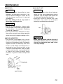
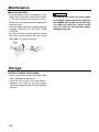
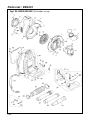
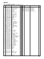
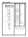
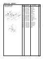
1
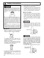
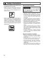
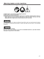
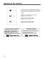
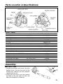
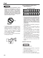
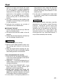
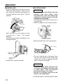
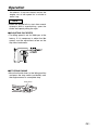
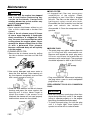
848L3A93A0 (309) OWNER / OPERATOR MANUAL BACKPACK BLOWER EB4401 WARNING The engine exhaust from this product contains chemicals known to the State of California to cause cancer, birth defects or other reproductive harm. APPLICABLE SERIAL NUMBERS : Thank you for purchasing a RedMax product. Before using our blower, please read this manual carefully to understand the proper use of your unit. 310001 and up Read this manual carefully to understand all safety precautions, controls, proper operation and maintenance of your RedMax blower. Failure to do so could result in serious injury. SAFETY FIRST Instructions contained in warnings within this manual and warning seals marked with a symbol on the blower concern critical points which must be taken into consideration to prevent possible serious bodily injury, and for this reason you are requested to read all such instructions carefully and follow them without fail. Note that there may be times when warning seals peel off or become soiled and impossible to read. If this happens, you should contact the dealer from which you purchased the product to order new seals and affix the new seal(s) in the required location(s). ■ Notes on types of warnings WARNING IMPORTANT NOTE Instructions labeled as shown at left, concern critical steps or procedures which must be followed in order to prevent accidents which could lead to serious bodily injury or death.This mark is used to indicate instructions which must be followed without exception. Instructions labeled as shown at left concern steps or procedures which, if not followed correctly, could lead to mechanical failure, breakdown, or damage. Used to label supplementary instructions designed to provide hints or directions useful in the use of the product. CONTENTS SAFETY PRECAUTIONS·······························································4 OPERATOR USE OF BLOWER FUEL WORKING CONDITION AVOID NOISE PROBLEM AVOID CHANCES OF DAMAGE WARNING LABELS ON THE MACHINE·······································7 SYMBOLS ON THE MACHINE······················································8 PARTS LOCATION & SPECIFICATIONS ······································9 ASSEMBLY ····················································································9 BLOWER TUBE FUEL·····························································································10 HOW TO MIX FUEL FUELING THE UNIT OPERATION·················································································12 CONTROL ARM STARTING ENGINE ADJUSTING IDLE SPEED STOPPING ENGINE MAINTENANCE ···········································································14 AIR CLEANER FUEL FILTER SPARK PLUG MUFFLER SPARK ARRESTER AIR INLET NET SHOULDER STRAP STORAGE ····················································································16 PARTS LIST ·················································································17 Safety Precautions WARNING • Read this Blower Owner/Operator Manual carefully. Be sure you understand how to operate this unit properly before you use it. Failure to do so could result in serious injury. • Be sure to keep this manual handy so that you may refer to it later whenever any questions arise. Also note that you are requested to contact the dealer from whom you purchased the product for assistance the event that you have any questions which cannot be answered herein. • Always be sure to include this manual when selling, lending, or otherwise transferring the ownership of this product. some other form of anti-slip protection to help protect you against falling. • To reduce the risk of injury associated with objects being drawn into rotating parts, do not wear loose clothing, scarves, neck chains, unconfined long hair, and the like. ■ USE OF BLOWER • Each time before starting the engine, inspect the entire unit to see if every part is in good order and is securely tightened in place. If any damage is found in the fuel line, the exhaust line, or the ignition wiring, do not use the blower until it has been repaired. IMPORTANT • Before starting operation, always make sure to check if any obstacles are left inside the volute case. The obstacles may cause damage on fan and volute case and serious injury. ■ OPERATOR • Refrain from operating the blower if you are tired, ill, or upset, or if you are under the influence of alcohol, drugs or medication. WARNING • To reduce the risk of hearing loss associated with sound level(s), hearing protection is required. • Always wear eye protection and foot protection. Eye protection should meet the requirements of ANSI Z87.1. • To reduce the risk of injury associated with the inhalation of dust, use a face filter mask in dusty conditions. • Wear rubber-soled shoes or shoes with 4 Check to see if the shock-absorbing rubber mount has become cracked or otherwise damaged. Note that failing to replace this rubber mount when it has become cracked or damaged may cause the engine to come loose from its frame during use, thus resulting in possible serious bodily injury. • If cracked, be sure to replace without delay. Safety Precautions WARNING • To reduce the risk of injury associated with contacting rotating parts, stop the engine before installing or removing attachments. Do not operate without net in place. Always disconnect the spark plug before performing maintenance or accessing movable parts. • Do not allow children to use blower. Make sure that each person you authorize to operate the blower understands all of the safety rules in this manual. • Avoid using any accessory or attachment other than those bearing the RedMax mark for use with the blower. • Drain the fuel from the fuel tank before transporting or storing the blower. • When storing the blower, choose a space indoors free from moisture and out of the reach of children. • Examine the blower at intervals for loose fasteners and rusted or damaged parts. Use special care around the fuel line, the muffler, and the ignition wiring. • All engine service except for those described in this manual should be performed by competent service personnel. Improper service to the blower fan and muffler could cause a hazardous failure. ■ FUEL WARNING To reduce the risk of fire and burn injury: • Handle fuel with care. It is highly flammable. • Do not smoke while handing fuel. • Do not refuel a hot engine. • Do not refuel a running engine. • Avoid spilling fuel or oil. Always wipe unit dry before using. • Move at least 10 ft. (3 meters) away from the fueling point before starting engine. • Always store gasoline in a container approved for flammable liquids. • Make sure the unit is properly assembled and in good operating condition. ■ WORKING CONDITION • Check the work area that the blower will be used in and remove or cover all valuables that may be damaged by the air blast or thrown debris. • To reduce the risk of injury associated with exhaust fume inhalation, do not operate in unventilated area. The exhaust gases contain harmful carbon monoxide. • Do not allow bystanders in work area. • Do not point the blower nozzle in the direction of people or pets. 5 Safety Precautions • Avoid using the blower where stable footing and balance are not assured. • Never to touch the spark plug or plug cord while the engine is in operation. Doing so may result in being subjected to an electrical shock. • Never to touch the muffler, spark plug, or other metallic parts of the engine while the engine is in operation or immediately after shutting down the engine. These metallic parts reach high temperatures during operation and doing so could result in serious burns. ■ AVOID NOISE PROBLEM NOTE Check and follow the local regulations as to sound level and hours of operations for blower. • Operate power equipment only at reasonable hours-not early in the morning or late at night when people might be disturbed. Comply with times listed in local ordinances. • To reduce sound levels, limit the number of pieces of equipment used at any one time. • Operate power blowers at the lowest possible throttle speed to do the job. • Check your equipment before operation, especially the muffler, air intakes and air filters. • Loosen compacted leaves, grass or debris with a rake or broom beforehand, so that the lowest possible throttle setting would get the job done. • In dusty conditions, slightly dampen surfaces or use mister attachment when water is available. ■ AVOID CHANCES OF DAMAGE • Watch out for children, pets, open windows or freshly washed cars, and blow debris safely away. • Use the full blower nozzle extension so the air stream can work close to the ground. • After using blowers and other equipment, CLEAN UP! Dispose of debris in trash receptacles. • Always check to be sure that no debris has been blown onto someone else’s property. 6 Warning labels on the machine (1) Read owner's manual before operating this machine. (2) Wear head, eye and ear protection. (3) Handling this machine improperly could result in accidents causing serious injury or death. Read this manual carefully and practice using the blower until you are fully acquainted with all operations and have learned to use it correctly. IMPORTANT If warning label peel off or become soiled and impossible to read, you should contact the dealer from which you purchased the product to order new labels and affix them in the required location(s). WARNING Never modify your machine. We won't warrant the machine, if you use the remodeled machine or you don't observe the proper usage written in the manual. 7 Symbols on the machine For safe operation and maintenance, symbols are carved in relief on the machine. According to these indications, please be careful not to make a mistake. (a) The port to refuel the "MIX GASOLINE" Position: FUEL TANK CAP (b) The direction to close the choke Position: AIR CLEANER COVER (c) The direction to open the choke Position: AIR CLEANER COVER IMPORTANT ENGINE INFORMATION THIS ENGINE CONFORMS TO US EPA PH1 AND 1995-1999 CALIFORNIA EMISSION REGULATIONS FOR ULGE ENGINES. ENGINE FAMILY : WKZXS. 0424ST ; EM ENGINE DISPLACEMENT : 41.5cc REFER TO OWNER'S MANUMAL FOR MAINTENANCE SPECIFICATIONS AND ADJUSTMENTS. MANUFACTURED : RedMax 8 Made in Japan INFORMATION IMPORTANTE CONCERNANT LE MOTEUR Ce moteur conformc aux normcs U.S. EPA PH1 et 1995-1999 de la régulementation concernant la pollution de l'air pour les petits moteurs tout-terrain. Type de moteur : WKZXS. 0424ST ; EM Cylindrée du moteur : 41,5cc Se référer au Manuel de l'utilisateur pour les spécifications d'entretien et les réglages. Manufacturé : RedMax Made in Japan Parts Location & Specifications MODEL EB4401 Dimensions ( L x W x H ) Dry Weight Fuel Tank Capacity Engine Type Piston Displacement Air Filter Carburetor ( Diaphragm ) Ignition System Spark Plug Muffler Durability Period Operating Engine Speed PIPE END Fuel Consumption Air Volume Air Volume (w/o Pipes) Air Velocity Noise Level mm ( in ) kg ( lbs ) liter ( fl. oz ) cc ( cu. in ) valve type hrs rpm liter/h ( fl. oz/h ) cu. m/min ( cfm ) cu. m/min ( cfm ) m/sec ( mph ) dB(A) 480 x 535 x 495 (189 x 211 x 195) 8.8 (19.3) 2.0 (67.6) Air cooled 2-cycle gasoline engine 41.5 (2.53) Regular size Rotary C.D.I Champion RJ6C (Noise-proof) Spark arrester equipped 300 2,000 to 6,500 ø57 1.7 (57.5) 11 (388) 18 (636) 72 (161) 72 Assembly ■ BLOWER TUBES 1.Connect the blower and swivel joint with flexible hose. Clamp both ends of the flexible hose securely with the hardware supplied with the unit. 2.Align the protrusion and the groove provided on the tube ends and twist the tube until connection is locked up. 9 Fuel WARNING • Gasoline is very flammable. Avoid smoking or bringing any flame or sparks near fuel. Make sure to stop the engine and allow it cool before refueling the unit. Select outdoor bare ground for fueling and move at least 3m (10ft) away from the fueling point before starting the engine. • The RedMax engines are lubricated by oil specially formulated for air-cooled 2-cycle gasoline engine use. If RedMax oil is not available, use an anti-oxidant added quality oil expressly labeled for air-cooled 2-cycle engine use. (JASO FC GRADE OIL or ISO EGC GRADE) • Do not use BIA or TCW (2-stroke watercooling type) mixed oil. ■ RECOMMENDED MIXING RATIO GASOLINE 50:OIL 1 50:1 MIXING CHART GASOLINE gal. 1 2 3 4 5 2-CYCLE OIL fl.oz 2.6 5.2 7.8 10.4 13 GASOLINE liter 2-CYCLE OIL ml 1 20 2 40 3 60 4 80 5 100 • Exhaust emission are controlled by the fundamental engine parameters and components(eq., carburation, ignition timing and port timing) without addition of any major hardware or the introduction of an inert material during combustion. • These engines are certified to operate on unleaded gasoline. • Make sure to use gasoline with a minimum octane number of 89 RON (USA/Canada: 87AL) • If you use a gasoline of a lower octane value than prescribed, there is a danger that the engine temperature may rise and an engine problem such as piston seizing may consequently occur. • Unleaded gasoline is recommended to reduce the contamination of the air for the sake of your health and the environment. • Poor quality gasolines or oils may damage sealing rings, fuel lines or fuel tank of the engine. ■ HOW TO MIX FUEL IMPORTANT Pay attention to agitation. 1. Measure out the quantities of gasoline and oil to be mixed. 2. Put some of the gasoline into a clean, approved fuel container. 3. Pour in all of the oil and agitate well. 4. Pour In the rest of gasoline and agitate 10 Fuel again for at least one minute. As some oils may be difficult to agitate depending on oil ingredients, sufficient agitation is necessary for the engine to last long. Be careful that, if the agitation is insufficient, there is an increased danger of early piston seizing due to abnormally lean mixture. 5. Put a clear indication on the outside of the container to avoid mixing up with gasoline or other containers. 6. Indicate the contents on outside of container for easy identification. ■ FUELING THE UNIT 1. Untwist and remove the fuel cap. Rest the cap on a dustless place. 2. Put fuel into the fuel tank to 80% of the full capacity. 3. Fasten the fuel cap securely and wipe up any fuel spillage around the unit. long period of time, clean the fuel tank after rendering it empty. Next, activate the engine and empty the carburetor of the composite fuel. 6. In the case of scrapping the used mixed oil container, scrap it only at an authorized repository site. NOTE As lot details of quality assurance, read the description in the section Limited Warranty carefully. Moreover, normal wear and change in product with no functional influence are not covered by the warranty. Also, be careful that, if the usage in the instruction manual is not observed as to fhe mixed gasoline, etc. described therein, if may not be covered by the warranty. WARNING 1. Select bare ground for fueling. 2. Move at least 10feet (3meters) away from the fueling point before starting the engine. 3. Stop the engine before refueling the unit. At that time, be sure to sufficiently agitate the mixed gasoline in the container. FOR YOUR ENGINE LIFE, AVOID; 1. FUEL WITH NO OIL(RAW GASOLINE) – It will cause severe damage to the internal engine parts very quickly. 2. GASOHOL – It can cause deterioration of rubber and/or plastic parts and disruption of engine lubrication. 3. OIL FOR 4-CYCLE ENGINE USE – It can cause spark plug fouling, exhaust port blocking, or piston ring sticking. 4. Mixed fuels which have been left unused for a period of one month or more may clog the carburetor and result in the engine failing to operate properly. 5. In the case of storing the product for a 11 Operation ■ CONTROL ARM 1.Hold the upper end of the control arm in hand and, while pulling it away from the unit, rotate arm forward (anti-clockwise as the arrow direction) until it clicks. (The first position) ■ STARTING ENGINE IMPORTANT • Avoid operating the blower with the flexible tube and swivel joint disconnected. That will reduce the cooling air and the engine could be damaged by overheating. 1.Push the primer bulb until fuel flows out in the clear tube. 2.When the engine is cool, close the choke. And if you want, you can rotate arm more forward until it clicks. (The second position) Choose the arm position according to your working condition. 3.Set the throttle lever in 1/3 open position. Full Throttle About 1/3 Open Idling To fold the arm, reverse the order. 4.To start, hold the top of the blower firmly with your left hand. Pull the starter knob slowly until you feel it engage and then give it a vigorous strong pull. IMPORTANT • Avoid pulling the starter rope out to its full extent and allowing the starter rope to snap back. This will prevent premature damage to the starter. • Do not let a person stand near the blower or the exhaust port. 5.Once the engine is running, gradually open 12 Operation the choke if it was set closed, and let the engine run at idle speed for a minute to warm it up. NOTE • When the engine fails to start after several attempts due to overchoking, open the choke and repeat pulling the rope. ■ ADJUSTING IDLE SPEED • The idling speed is set for 2000 rpm at the factory. If it is necessary to adjust the idle speed, use the adjustment screw on the top side of carburetor. ■ STOPPING ENGINE • Move the throttle lever to the idling position and press the stop switch (red button) until the engine comes to a complete stop. Stop Switch 13 Maintenance WARNING • Make sure that the engine has stopped and is cool before performing any service to the blower. Contact with rotating blower fan or hot muffler may result in a personal injury. ■ AIR CLEANER • Never operate the blower without an air filter or with a deformed or broken filter element. • C h e c k the air cleaner every 25 hours of use or more frequently if used under dusty conditions. A clogged air filter may increase fuel consumption while cutting down the engine power. Never operate the blower without the air filter or with a deformed filter element because unfiltered dusty air will quickly ruin the engine. CLEANING AIR FILTER: 1.Remove the air cleaner cover by pulling the tab on bottom and take out the filter element. 2.Use neutral detergent and warm water to clean the filter element. After cleaning, air dry the element completely and moisten with a small amount of motor oil. ■ FUEL FILTER • A clogged fuel filter may cause poor acceleration of the engine. Check periodically to see if the filter is clogged with dirt. The filter can be taken out of the fueling port using a small wire hook. Disconnect the filter assembly from the fuel pipe and unhook the retainer to disassemble it. Clean the components with gasoline. ■ SPARK PLUG • The spark plug may gather carbon deposits on its firing end with reasonable use. Remove and inspect the spark plug every 25 hours and clean the electrodes as necessary with a wire brush. The spark gap should be adjusted to .025 in (0.6~0.7mm). • Plug manufacturers recommend replacing the plug twice a year to avoid unexpected plug failure in a job. REPLACEMENT PLUG IS A CHAMPION RJ6C. 3.Place the filter element into the air cleaner housing and press the cover against the housing until it clicks. Never forget to attach the screen. If the screen is not attached, the cleaner will not seal properly and the dusts come into the cylinder. 14 IMPORTANT • Note that using any spark plugs other than those designated may result in the engine failing to operate properly or in the engine becoming overheated and damaged. • To install the spark plug, first turn the plug until it is finger tight, then tighten it a quarter turn more with a socket wrench. Maintenance ■ MUFFLER WARNING • Inspect periodically, the muffler for loose fasteners, any damage or corrosion. If any sign of exhaust leakage is found, do not use the blower and have it repaired immediately. • Note that failing to do so may result in the engine catching on fire. ■ AIR INLET NET IMPORTANT • Blowing air is taken in from the air inlet net. When air flow has dropped down during operation, stop the engine and inspect the air inlet net for blocking by obstacles. • Note that failure to remove any such obstacles may result in the engine becoming overheated and damaged. IMPORTANT • Before starting operation, always make sure to check if the muffler is properly held by three bolts to the cylinder. (Fastening Torque : 80~120kg·cm) • Even if one bolt out of three bolts is loose, the muffler may get loose during operation which may result in engine catching on fire. ■ SPARK ARRESTER • The muffler is equipped with a spark arrester to prevent red hot carbon from flying out of the exhaust outlet. Periodically inspect and clean as necessary with a wire brush. In the State of California it is required by law (Section 4442 of the California Public Resources Code) to equip a spark arrester when a gas powered tool is used in any forest covered, brush covered, or grass covered unimproved land. WARNING • Never use the blower without the net of the blower. Before each use, check that the net is attached in place and is free from any damage. 15 Maintenance ■ SHOULDER STRAP • If the shoulder strap is damaged it may break during use, thus causing the product to fall and resulting in personal injury. Follow the instructions below to replace the shoulder strap. • Pass the upper end of the strap through the hanger, making the FLAPPED SIDE OUTSIDE. • Put the end of the strap through the ring on the strap, and then push the ring toward the hanger as close as possible. Storage BEFORE STORING THE BLOWER: 1.Drain a fuel tank and push the primer bulb until it becomes empty of fuel. 2.Remove the spark plug and drop a spoonful of 2-cycle oil into the cylider. Crank the engine several time and replace the plug. 16 WARNING • The flap on the end of the strap works as a stopper. Never install the strap with the flapped side inside, or the unit may fall from the operator, which could result in injury to the operator and/or damage to the unit. Parts List BACKPACK BLOWER EB4401 NOTE : 1. Use KOMATSU ZENOAH genuine parts as specified in the parts list for repair and/or replacement. 2. KOMATSU ZENOAH does not warrant the machines, which have been damaged by the use of any parts other than those specified by the company. 3. When placing parts orders for repair and/or replacement, check if the model name and the serial number are applicable to those specified in the parts list, then use parts number described in the parts list. 4. The contents described in the parts list may change due to improvement. 5. The parts for the machine shall be supplied seven (7) years after the machine is discontinued. [It is possible that some specific parts may be subject to change of their delivery term and list price within the limit of seven (7) years after the machine is discontinued. It is also possible that some parts may be available even after the limit of seven (7) years.] APPLICABLE SERIAL NUMBERS : 310001 and up 17 Parts List : EB4401 Fig.1 BLOWER GROUP (S/N 310001 and up) 18 EB4401 Fig.1 BLOWER GROUP (S/N 310001 and up) Key# Part Number Description Q'ty Key# 1 2 3 4 5 6 7 8 9 10 11 12 13 14 15 16 17 18 19 20 21 22 23 24 25 26 27 28 29 30 31 32 33 34 35 36 37 38 39 40 41 42 43 44 2750-31111 2750-31212 2750-31150 3490-11150 07000-02095 2750-31420 3310-53331 T4012-31310 2750-31150 1140-72231 3407-16120 2750-31290 2750-31911 T4012-32610 2750-31510 3407-12210 2750-31612 2750-31150 2750-72230 T4012-32002 T4012-32101 3490-21121 3460-21311 3495-21320 2756-32300 T4012-32500 1480-74710 2750-32510 2750-32520 2750-32530 2750-32541 2750-32610 2750-32620 2756-85102 T1015-85202 4500-85300 4500-85220 5601-85260 4820-85260 2756-85300 3302-85400 1260-85460 3407-23610 1100-86120 VOLUTE CASE VOLUTE COVER SCREW M5x25 ELBOW O-RING SCREW M5x70 NUT COVER INLET SCREW M5x25 CLAMP SCREW M5x14 TUBE LABEL LABEL, net FAN BOLT M5x40 ENGINE COVER SCREW M5x25 CLAMP FRAME ASSY • FRAME COMP • RING PAD CLIP BAND ASSY NET COMP CLIP DAMPER,UPPER WASHER SCREW M5x40 BOLT M5x16 (Large Washer) DAMPER,LOWER NUT M6 TANK ASSY • CAP ASSY • • HOLDER ASSY • • PACKING • • FILTER • • STOPPER • PIPE COMP • FILTER • CLIP SCREW CLIP 1 1 9 1 1 2 2 1 3 1 1 1 1 1 1 4 1 4 1 1 1 2 1 4 2 1 4 1 1 1 2 2 2 1 1 1 1 1 1 1 1 1 2 1 66 67 68 69 70 61 62 63 T4017-51110 2750-51201 6811-51211 HOSE SWIVEL JOINT PIPE, straight 1 1 1 65 2756-51510 CLAMP 1 Part Number 2756-51520 3407-91000 3540-91120 3407-91130 2756-51220 Description CLAMP TOOL SET • SPANNER • SOCKET PIPE, end ø57 Q'ty 1 1 1 1 1 19 Parts List : EB4401 Fig.2 ENGINE GROUP (S/N 310001 and up) 20 EB4401 Fig.2 ENGINE GROUP (S/N 310001 and up) Key# Part Number 1 2 3 4 5 6 7 8 9 10 11 12 13 14 15 16 17 18 19 20 21 22 23 24 25 26 27 28 29 30 31 32 33 34 35 36 37 38 39 40 1490-12114 2756-12210 1850-12130 1484-13161 2756-13120 2756-13130 1484-13170 1491-32110 2750-12520 2756-15100 1421-15120 2750-15210 2750-15160 2750-15170 2756-21100 2756-21140 T4012-21240 T4019-21210 T1108-21220 01252-30530 04065-03515 2750-21211 1565-72211 1483-41111 1400-41220 1490-41310 3350-41320 1400-41410 2616-41510 2756-42000 1300-42410 1400-43230 1000-43240 2750-71111 2750-71200 3350-14150 1900-72112 1900-72120 5500-72130 1497-73110 41 42 43 44 45 2756-71220 2756-73200 1487-75101 1180-75221 1487-75120 Description Cylinder Gasket, base Bolt M5x20 Insulator Gasket Gasket Bolt Cover Bolt M5x10 Muffler ass’y • Arrester Gasket Bolt M6x70 Bolt M6x12 Crankcase comp Gasket Bearing 15x35x11 Oil seal 15x25x7 Oil seal 15x35x6 Bolt Snap ring Cover Bolt M4x16 Piston φ40 Ring Piston pin Snap ring Bearing Washer Crankshaft comp Shim Nut M10(P=1.0) Key Rotor Coil ass’y Bolt M4x20 Cap Spring Grommet Spark plug (Champion RJ6C) Cap Cord comp Recoil ass’y • Spring • Reel Q'ty Key# Part Number Description Q'ty 1 1 4 1 1 1 2 1 2 1 1 1 2 1 1 1 3 1 1 4 1 1 1 1 2 1 2 1 2 1 0~1 2 1 1 1 2 1 1 1 1 46 47 48 49 50 51 52 53 54 55 56 57 58 59 60 61 62 63 64 65 66 67 68 69 70 1487-75140 1861-75150 1483-75270 1487-75160 1487-75170 1400-75160 1400-75170 1487-75211 3460-75510 848L3A90C0 3407-81000 3407-82102 3407-82130 3407-82140 2630-33610 1487-82201 1487-82210 5500-82230 1491-82311 1484-82510 0263-90560 1491-82352 1491-82360 1133-82060 2750-21510 • Dog • Washer • Screw • Retainer • Washer • Rope • Knob Pulley Bolt M5x20 Label Carburetor (WYK-67) Body ass’y • Plate • Lever • Screw Cover ass’y • Knob • Ring Element Plate Screw Screen Screw, Tapping φ5x6 Label Bolt M6x40 1 1 1 1 1 1 1 1 4 1 1 1 1 1 1 1 1 1 1 1 2 1 1 1 6 101 102 103 104 105 106 2756-05011 2756-06010 2750-96100 3350-96220 3350-96230 2750-96240 Short block Gasket kit Puller ass’y Stopper Guide Gauge OP OP OP OP OP OP 1 1 1 1 1 21 Parts List : EB4401 Fig.3 CARBURETOR COMPONENTS (S/N 310001 and up) Carburetor Ass’y (WYK-67) P/NO. 3407-81000 Key# Part Number Description Q'ty 1 2 3 4 5 6 7 8 9 10 11 12 13 14 15 16 17 18 19 20 21 22 23 24 25 26* 27* 28 1850-81450 ————— ————— ————— ————— ————— ————— 1850-81490 1850-81520 1751-81510 5500-81160 1881-81140 1751-81130 ————— ————— ————— ————— 1752-81110 5500-81120 1751-81180 1918-81170 1881-81130 1850-81530 3407-81250 1751-81240 ————— ————— 5602-06020 1 1 1 1 1 1 1 1 1 1 1 1 1 1 1 1 1 2 1 1 1 1 4 1 1 1 1 OP 29 5602-06030 Body ass’y Screen Valve Spring Screw Pin Lever Body Cover Pump Washer Swivel Ring Gasket Diaphragm Gasket Diaphragm Screw Bracket Nut Screw Ring Screw Jet O-Ring Body Valve ass’y Gasket Kit (Key# 14,15,16,17) Rebuild Kit (Gasket Kit + Key# 1) OP [NOTE] • 26*-Body and 27*-Valve ass’y are not supplied as an individual part respectively, but supplied as a carburetor ass’y (P/NO. 3407-81000). 22 Parts List : EB4401 Fig.4 LEVER SET (S/N 310001 and up) Key# Part Number 1 2 3 4 5 6 7 8 9 10 11 12 13 14 15 16 17 18 19 20 21 T4012-25001 T4012-25100 3310-53331 01642-20508 T4012-25211 T4012-25311 3495-25410 3495-25420 3495-25440 01584-00605 3495-25450 T4012-25511 T4012-83110 T4012-25610 1601-72411 2750-51501 2750-51520 3495-51430 3238-15230 2750-51540 2750-32541 Description LEVER SET • LEVER • NUT M5 • WASHER • ARM • BRACKET • BOLT • SPRING • WASHER • NUT • WASHER • SWITCH • CABLE COMP • TUBE • CAP GRIP ASSY • WING BOLT • WING NUT • WASHER • NUT BOLT Q'ty 1 1 1 1 1 1 1 1 1 1 2 1 1 1 1 1 1 1 2 1 2 23 CALIFORNIA EMISSION CONTROL WARRANTY STATEMENT YOUR WARRANTY RIGHTS AND OBLIGATIONS The California Air Resources Board and KOMATSU ZENOAH are pleased to explain the emission control system warranty on your 1995 and later small off-road engine. In California, new small off-road engines must be designed, built and equipped to meet the state’s stringent anti-smog standards. KOMATSU ZENOAH must warrant the emission control system on your small off-road engine for the periods of time listed below provided there has been no abuse, neglect or improper maintenance of your small off-road engine. Your emission control system may include parts such as the carburetor and the ignition system. Where a warrantable condition exists, KOMATSU ZENOAH will repair your small off-road engine at no cost to you including diagnosis, parts and labor. Manufacturer’s warranty coverage: The 1995 and later small off-road engines are warranted for two years. If any emissionrelated part on your engine is defective, the part will be repaired or replaced by KOMATSU ZENOAH. Owner’s warranty responsibilities: – As the small off-road engine owner, you are responsible for the performance of the required maintenance listed in your owner’s manual. KOMATSU ZENOAH recommends that you retain all receipts covering maintenance on your small off-road engine, but KOMATSU ZENOAH can not deny warranty solely for the lack of receipts or for your failure to ensure the performance of all scheduled maintenance. – As the small off-road engine owner, you should be aware, however, that KOMATSU ZENOAH may deny you warranty coverage if your small off-road engine or a part has failed due to abuse, neglect, improper maintenance or unapproved modification. – You are responsible for presenting your small off-road engine to a KOMATSU ZENOAH distribution center as soon as a problem exists. The warranty repairs should be completed in e reasonable amount of time, not to exceed 30 days. If you have any questions regarding your warranty rights and responsibilities, you should contact KOMATSU ZENOAH AMERICA INC. at (770)-381-5147 or you can write to KOMATSU ZENOAH AMERICA INC. 4344 Shackleford Road Suite 500 Norcross, Georgia 30093 RedMax LIMITED WARRANTY EMISSION-RELATED PARTS, FOR TWO (2) YEARS FROM THE DATE OF ORIGINAL DELIVERY OF THE UNIT, KOMATSU ZENOAH AMERICA INC. (THE COMPANY), THROUGH ANY RedMax DEALER, WILL REPAIR OR REPLACE, FREE OF CHARGE, FOR THE ORIGINAL AND EACH SUBSEQUENT PURCHASER, ANY PART OR PARTS FOUND TO BE DEFECTIVE IN MATERIAL AND/OR WORKMANSHIP. EMISSION-RELATED PARTS ARE: THE CARBURETOR ASSY, COIL ASSY, ROTOR, SPARKPLUG, AIR FILTER, FUEL FILTER, INTAKE MANIFOLD, AND THE GASKETS ALL OTHER PARTS EXCEPT ABOVE PARTS, FOR TWO (2) YEARS OF USE, 90 DAYS FOR RENTAL USE, FROM THE DATE OF ORIGINAL PURCHASE, THE COMPANY, THROUGH ANY RedMax DEALER, WILL REPAIR OR REPLACE, FREE OF CHARGE, FOR THE ORIGINAL PURCHASER, ANY PART OF PARTS FOUND TO BE DEFECTIVE IN MATERIAL AND/OR WORKMANSHIP. THIS IS THE EXCLUSIVE REMEDY. THE PURCHASER SHALL BEAR COSTS OF TRANSPORTING THE UNIT TO AND FROM THE RedMax DEALER. THE PURCHASER SHALL NOT BE CHARGED FOR DIAGNOSTIC LABOR WHICH LEADS TO THE DETERMINATION THAT A WARRANTED PART IS DEFECTIVE, IF THE DIAGNOSTIC WORK IS PERFORMED AT THE RedMax DEALER. THE PURCHASER OR OWNER IS RESPONSIBLE FOR THE PERFORMANCE OF THE REQUIRED MAINTENANCE AS DEFINED BY THE MANUFACTURER IN THE OWNER/OPERATOR MANUAL. ANY WARRANTED PART WHICH IS NOT SCHEDULED FOR REPLACEMENT AS REQUIRED MAINTENANCE, OR WHICH IS SCHEDULED ONLY FOR REGULAR INSPECTION TO THE EFFECT OF "REPAIR OR REPLACE AS NECESSARY" SHALL BE WARRANTED FOR THE WARRANTY PERIOD.ANY WARRANTED PART WHICH IS SCHEDULED FOR REPLACEMENT AS REQUIRED MAINTENANCE SHALL BE WARRANTED FOR THE PERIOD OF TIME UP TO THE FIRST SCHEDULED REPLACEMNET POINT FOR THE PART. ANY REPLACEMENT PART THAT IS EQUIVALENT IN PERFORMANCE AND DULABILITY MAY BE USED IN NONWARRANTY MAINTENANCE OR REPAIRS, AND SHALL NOT REDUCE THE WARRANTY OBLIGATION OF THE COMPANY. THE COMPANY IS LIABLE FOR DAMAGES TO OTHER ENGINE COMPONENTS CAUSED BY THE FAIRURE OF A WARRANTED PARTS STILL UNDER WARRANTY. THE WARRANTY DOES NOT APPLY TO THOSE UNITS WHICH HAVE BEEN DAMAGED BY NEGLIGENCE OF INSTRUCTION LISTED IN THE OWNER/OPERATOR MANUAL FOR PROPER USE AND MAINTENANCE OF THE UNITS, ACCIDENT MISHANDLING, ALTERATION, ABUSE, IMPROPER LUBULICATION, USE OF ANY PARTS OR ACCESSARIES OTHER THAN THOSE SPECIFIED BY THE COMPANY, OR OTHER CAUSES BEYOND THE CONPANY'S CONTROL. THIS WARRANTY DOES NOT COVER THOSE PARTS REPLACED BY NORMAL WEAR OR HARMLESS CHANGES IN THEIR APPEARANCE. THERE ARE NO OTHER EXPRESS WARRANTIES. IMPLIED WARRANTIES INCLUDING THOSE OF MERCHANTABILITY AND FITNESS FOR A PARTICULAR PURPOSE ARE LIMITED TO TWO (2) YEARS OF USE FROM THE ORIGINAL DELIVERY DATE. LIABILITIES FOR INCIDENTAL OR CONSEQUENTIAL DAMAGE UNDER ANY AND ALL WARRANTIES ARE EXCLUDED. SOME STATES DO NOT ALLOW LIMITATION ON HOW LONG AN IMPLIED WARRANTY LASTS OR EXCLUSION OR LIMITATION OF INCIDENTAL OR CONSEQUENTIAL DAMAGES, SO THE ABOVE LIMINATION OR EXCLUSION MAY NOT APPLY TO YOU. THIS WARRANTY GIVES YOU SPECIFIC LEGAL RIGHTS, AND YOU MAY ALSO HAVE OTHER RIGHTS WHICH VARY FROM STATE TO STATE. IF YOU NEED TO OBTAIN INFORMATION ABOUT THE NEAREST SERVICE CENTER, PLEASE CALL KOMATSU ZENOAH AMERICA INC. AT (770)-381-5147. IMPORTANT: YOU WILL RECEIVE A WARRANTY REGISTRATION CARD AT TIME OF PURCHASE.PLEASE FILL OUT THE CARD AND SEND IT TO RedMax / KOMATSU ZENOA AMERICA WITHIN SEVEN (7) DAYS.BE SURE TO KEEP A COPY FOR YOUR RECORDS. KOMATSU ZENOAH AMERICA INC. 4344 Shackleford Road Suite 500 Norcross, Georgia 30093 RedMax Garantie limitée Pièces en rapport avec les émissions de gaz d'échappement : KOMATSU ZENOAH AMERICA INC., par l'intermédiaire de n'importe quel revendeur RedMax, réparera gratuitement ou remplacera gratuitement pour l'acheteur initial et chaque acheteur successif toute(s) pièce(s) se révélant de constitution et/ou de montage défectueux pendant deux (2) ans à compter de la date initiale de livraison d’une unité. Les pièces en rapport avec les émissions de gaz d'échappement sont: l'assemblage carburateur, l'assemblage bobine, le rotor, la bougie, le filtre à air, le filtre à carburant, la tubulure d'admission et les joints Toutes les pièces autres que celles mentionnées ci-dessus, deux (2) ans d’utilisation, 90 jours pour la location, à compter de la date d’achat initial. La société, par l’intermédiaire d’un distributeur RedMax, réparera ou remplacera toute(s) pièce(s), sans frais et au bénéfice de l’acheteur original, en prenant en charge les frais de pièces et/ou de main d’œuvre. Telles sont les limites de la garantie. Le coût du transport de l'unité jusqu'au revendeur RedMax et depuis celui-ci sera à la charge de l'acheteur. L'acheteur ne supportera pas le coût de main d'oeuvre du diagnostic qui amène à la conclusion qu'une pièce garantie est défectueuse, si ce diagnostic est effectué chez le revendeur RedMax. L’acheteur ou propriétaire a pour responsabilité d’effectuer l’entretien obligatoire tel que défini par le fabricant dans le manuel du propriétaire/de l'utilisateur. Toute pièce garantie dont le remplacement n'est pas prévu dans le cadre de l’entretien obligatoire, ou pour laquelle est seulement prévue une inspection périodique pour "remplacement ou réparation si nécessaire" sera garantie pour la période de garantie. Toute pièce garantie arrivée à l’échéance de son premier remplacement prévu sera garantie jusqu’à celui-ci. Toute pièce de rechange équivalente en performance ou en durabilité peut être utilisée pour l’entretien hors-garantie ou les réparations hors-garantie, et ce sans réduire l’obligation de garantie incombant à la société. La société sera tenue responsable des dommages aux autres composants du moteur causés par la défaillance de pièce(s) garantie(s) en période de garantie. La garantie ne s'applique pas aux unités endommagées par suite de: négligence dans la mise en oeuvre des instructions spécifiées dans le manuel du propriétaire/de l'utilisateur en vue d’une utilisation et d’un entretien correct, fausse manœuvre accidentelle, modification, utilisation abusive, lubrification incorrecte, utilisation de pièces ou d’accessoires autres que ceux spécifiés par la société, ou autres causes hors du contrôle de la société. Cette garantie ne couvre pas les pièces remplacées en raison de leur usure normale ou de changements d’apparence sans effets. Il n'existe aucune autre garantie explicite. Les garanties implicites, y compris la valeur marchande et la valeur d’usage pour une utilisation particulière, sont limitées à deux (2) ans d’utilisation à compter de la date originale de livraison. Les responsabilités pour les dommage conséquents ou incidents sont exclues de toutes les garanties. Certaines provinces n'autorisant pas les limitations à la durée des garanties implicites, ou les exclusions ou limitations relatives aux dommages incidents ou conséquents, la limitation indiquée ci-dessus peut ne pas vous être applicable. Cette garantie vous donne des droits juridiques spécifiques, et vous pouvez également jouir d’autres droits variant d'une province à l'autre. Si vous désirez obtenir des informations sur le centre de service le plus proche, veuillez appeler KOMATSU ZENOAH AMERICA INC. au (770)-381-5147 Note importante: vous recevrez une carte d'enregistrement de garantie au moment de l'achat. Veuillez la remplir et l'adresser à RedMax / KOMATSU ZENOAH AMERICA sous sept (7) jours en prenant soin de conserver une copie pour vous. KOMATSU ZENOAH AMERICA INC. 4344 Shackleford Road Suite 500 Norcross, Georgia 30093 KOMATSU ZENOAH AMERICA INC. 4344 Shackleford Road Suite 500 Norcross, Georgia 30093