1
LC-15A2U
SERVICE MANUAL
S60B6LC-15A2U
SERVICE MANUAL
LCD COLOR TELEVISION
MODEL
LC-15A2U
LCD COLOR TELEVISION
In the interests of user-safety (Required by safety regulations in some countries) the set should be restored to its
original condition and only parts identical to those specified
be used.
CONTENTS
MODEL LC-15A2U
Page
IMPORTANT SERVICE SAFETY PRECAUTION ................................................................................. 2
ELECTRICAL SPECIFICATIONS ......................................................................................................... 4
OPERATION MANUAL ......................................................................................................................... 5
SUPPLIED ACCESSORIES ................................................................................................................. 6
OUTLINE DIMENSION FIGURE .......................................................................................................... 7
DISASSEMBLY OF THE SET ............................................................................................................... 8
ADJUSTING PROCEDURE OF EACH SECTION ............................................................................... 9
TROUBLE SHOOTING TABLE ........................................................................................................... 11
CHASSIS LAYOUT ............................................................................................................................. 14
BLOCK DIAGRAM .............................................................................................................................. 16
DESCRIPTION OF SCHEMATIC DIAGRAM ..................................................................................... 18
SCHEMATIC DIAGRAM ..................................................................................................................... 19
PRINTED WIRING BOARD ASSEMBLIES ........................................................................................ 26
PARTS LIST
Ë ELECTRICAL PARTS ..................................................................................................................... 31
MAIN UNIT ..................................................................................................................................... 31
TERMINAL UNIT ............................................................................................................................ 36
SWITCH UNIT ................................................................................................................................ 37
R/C UNIT ........................................................................................................................................ 37
Ë ACCESSORIES PARTS ................................................................................................................. 37
Ë PACKING PARTS ........................................................................................................................... 37
Ë CABINET PARTS LIST ................................................................................................................... 38
Ë CABINET AND MECHANICAL PARTS .......................................................................................... 39
» PACKING OF THE SET ...................................................................................................................... 40
»
»
»
»
»
»
»
»
»
»
»
»
»
»
SHARP CORPORATION
This document has been published to be used for
after sales service only.
The contents are subject to change without notice.
1
LC-15A2U
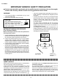
IMPORTANT SERVICE SAFETY PRECAUTION
Ë
Service work should be perfomed only by qualified service technicians who are thoroughly
familiar with all safety checks and the servicing guidelines which follow:
WARNING
•
1. For continued safety, no modification of any circuit
should be attempted.
2. Disconnect AC power before servicing.
•
CAUTION
FOR CONTINUED PROTECTION
AGAINST A RISK OF FIRE REPLACE
A
ONLY WITH SAME TYPE FUSE.
F3701 (1.6A, 125V), F3702 (1.6A, 125V), F3751
(2.5A, 125V) FUSE.
V
BEFORE RETURNING THE RECEIVER
(Fire & Shock Hazard)
Use an AC voltmeter having with 5000 ohm per volt, or
higher, sensitivity or measure the AC voltage drop across
the resisor.
Connect the resistor connection to all exposed metal
parts having a return to the chassis (antenna, metal
cabinet, screw heads, knobs and control shafts,
escutcheon and etc.) and measure the AC voltage drop
across the resistor.
All checks must be repeated with the AC cord plug
connection reversed. (If necessary, a nonpolarized
adaptor plug must be used only for the purpose of
completing these checks.)
Any reading of 0.75V peak (this corresponds to 0.5
milliamp. peak AC.) or more is excessive and indicates
a potential shock hazard which must be corrected before
returning the monitor to the owner.
Before returning the receiver to the user, perform the
following safety checks:
1. Inspect all lead dress to make certain that leads are not
pinched, and check that hardware is not lodged between
the chassis and other metal parts in the receiver.
2. Inspect all protective devices such as non-metallic
control knobs, insulation materials, cabinet backs,
adjustment and compartment covers or shields, isolation
resistor-capacitor networks, mechanical insulators, etc.
3. To be sure that no shock hazard exists, check for leakage
current in the following manner.
• Plug the AC cord directly into a 110~240 volt AC outlet,
and connect the DC power cable into the receiver's DC
jack. (Do not use an isolation transformer for this test).
• Using two clip leads, connect a 1.5k ohm, 10 watt resistor
paralleled by a 0.15µF capacitor in series with all
exposed metal cabinet parts and a known earth ground,
such as electrical conduit or electrical ground connected
to earth ground.
DVM
AC SCALE
50k ohms.
10W
0.15 µF
TEST PROBE
TO EXPOSED
METAL PARTS
CONNECT TO
KNOWN EARTH
GROUND
12345678901234567890123456789012123456789012345678901234567890121234567890123456789012345678901212345
12345678901234567890123456789012123456789012345678901234567890121234567890123456789012345678901212345
12345678901234567890123456789012123456789012345678901234567890121234567890123456789012345678901212345
12345678901234567890123456789012123456789012345678901234567890121234567890123456789012345678901212345
SAFETY NOTICE
and shaded areas in the Replacement Parts Lists and
Schematic Diagrams.
For continued protection, replacement parts must be
identical to those used in the original circuit.
The use of a substitute replacement parts which do not
have the same safety characteristics as the factory
recommended replacement parts shown in this service
manual, may create shock, fire or other hazards.
Many electrical and mechanical parts in LCD television
have special safety-related characteristics.
These characteristics are often not evident from visual
inspection, nor can protection afforded by them be
necessarily increased by using replacement components
rated for higher voltage, wattage and etc.
Replacement parts which have these special safety
characteristics are identified in this manual; electrical
components having such features are identified by “ å”
12345678901234567890123456789012123456789012345678901234567890121234567890123456789012345678901212345
12345678901234567890123456789012123456789012345678901234567890121234567890123456789012345678901212345
12345678901234567890123456789012123456789012345678901234567890121234567890123456789012345678901212345
2
LC-15A2U
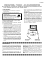
PRECAUTIONS A PRENDRE LORS DE LA REPARATION
Ë
Ne peut effectuer la réparation qu’ un technicien spécialisé qui s’est parfaitement accoutumé
à toute vérification de sécurité et aux conseils suivants.
•
AVERTISSEMENT
1. N’entreprendre aucune modification de tout circuit.
C’est dangereux.
2. Débrancher le récepteur avant toute réparation.
•
PRECAUTION
POUR LA PROTECTION CONTINUE
A
CONTRE LES RISQUES D’INCENDIE,
REMPLACER LE FUSIBLE PAR UN FUSIBLE
DE MEME TYPE F3701 (1,6A, 125V), F3702
(1,6A, 125V), F3751 (2,5A, 125V).
V
VERIFICATIONS CONTRE L’INCEN-DIE ET
LE CHOC ELECTRIQUE
Avant de rendre le récepteur à l’utilisateur, effectuer
les vérifications suivantes.
1. Inspecter tous les faisceaux de câbles pour s’assurer
que les fils ne soient pas pincés ou qu’un outil ne soit
pas placé entre le châssis et les autres pièces
métalliques du récepteur.
2. Inspecter tous les dispositifs de protection comme les
boutons de commande non-métalliques, les isolants,
le dos du coffret, les couvercles ou blindages de
réglage et de compartiment, les réseaux de résistancecapacité, les isolateurs mécaniques, etc.
3. S’assurer qu’il n’y ait pas de danger d’électrocution en
vérifiant la fuite de courant, de la facon suivante:
• Brancher le cordon d’alimentation dans la prise CA de
110~240 V et le câble d’alimentation CC dans le jack
du moniteur. (Ne pas utiliser un transformateur pour
cet essai.)
• A l’aide de deux fils à pinces, brancher une résistance
de 1,5kΩ 10 watts en paralléle avec un condensateur
de 0,15µF en série avec toutes les pièces métalliques
exposées du coffret et une terre connue comme une
conduite électrique ou une prise de terre branchée à
la terre.
Utiliser un voltmètre CA d’une sensibilité d’au moins
5000Ω/V pour mesurer la chute de tension en travers
de la résistance.
Toucher avec la sonde d’essai les piéces métalliques
exposées qui présentent une voie de retour au châssis
(antenne, coffret métallique, tête des vis, arbres de
commande et des boutons, écusson, etc.) et mesure
la chute de tension CA en-travers de la résistance.
Toutes les vérifications doivent être refaites aprés avoir
inversé la fiche du cordon d’alimentation. (Si
nécessaire, une prise d’adpatation non polarisée peut
être utilisée dans le but de terminer ces vérifications.)
Une valeur de 0,75 V RMS ou plus (correspond à 0,5
mA C.A.) est excessive et implique un danger de
secousse électrique, qui devra être supprimé avant
de retourner l'appareil à l'utilisateur.
VTVM
ECHELLE CA
1.5 KOHMS
10W
0,15 µF
SONDE D'ESSAI
VERS PIECES
METALLIQUES
EXPOSEES
CANNECTER A
UNE MASSE DE
TERRE CONNUE
1234567890123456789012345678901212345678901234567890123456789012123456789012345678901234567890121234
1234567890123456789012345678901212345678901234567890123456789012123456789012345678901234567890121234
1234567890123456789012345678901212345678901234567890123456789012123456789012345678901234567890121234
SAFETY NOTICE
identifiées par la marque “ å” et hachurées dans la liste
des pièces de remplacement et les diagrammes
schématiques.
Pour assurer la protection, ces pièces doivent être
identiques à celles utilisées dans le circuit d’origine.
L’utilisation de pièces qui n’ont pas les mêmes
caractéristiques que les pièces recommandées par l’usine,
indiquées dans ce manuel, peut provoquer des
électrocutions, incendies, radiations X ou autres accidents.
1234567890123456789012345678901212345678901234567890123456789012123456789012345678901234567890121234
1234567890123456789012345678901212345678901234567890123456789012123456789012345678901234567890121234
1234567890123456789012345678901212345678901234567890123456789012123456789012345678901234567890121234
De nombreuses pièces, électriques et mécaniques, dans
les téléviseurs présentent des caractéristiques spéciales
relatives à la sécurité, qui ne sont souvent pas évidentes
à vue. Le degré de protection ne peut pas être
nécessairement augmentée en utilisant des pièces de
remplacement étalonnées pour haute tension, puissance,
etc.
Les pièces de remplacement qui présentent ces
caractéristiques sont identifiées dans ce manuel; les
pièces électriques qui présentent ces particularités sont
3
LC-15A2U
ELECTRICAL SPECIFICATIONS
Power input ....................................................................................... DC 12V (Receiver)
....................................................................................... AC 110-240V (AC Adapter)
Power consumption ......................................................... 27 W (Connected to DC 12V)
LCD panel size .......................................................................................... 15" TFT LCD
Number of pixels ........................................................................... 921,600 pixels (VGA)
Video color systems ......................................................................... PAL/NTSC/SECAM
Audio amplifier ............................................... (Front) 0.6 W + 0.6 W (at 10% distortion)
.............................................................................................................. (Rear) 2.5 W
Speakers
Size .......................................................... (Front)1-3/16 × 1-37/64 in. (3 × 4 cm) (2 pcs)
............................................................................................... (Rear) φ65 mm (1 pcs)
Voice coil impedance ......................................................................... (Front) 32 ohm
Voice coil impedance ............................................................................ (Rear) 6 ohm
Antenna input impedance ............................................................... 75 ohm unbalanced
Tuning ranges
VHF Channels ............................................................................................. 2 thru 13
UHF Channels ........................................................................................... 14 thru 69
CATV Channels .........................................................................................1 thru 125
......................................................................................... (EIA, Channel Plan U.S.A)
Weight ......................................................................... 8.2 lbs (3.7 kg), w/o accessories
Accessories ................................ R/C, Batteries, Antenna cable, AC adapter, AC cord,
Operation manual, Cable Clamp
Specifications are subject to change without prior notice.
4
LC-15A2U
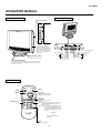
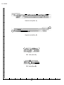
OPERATION MANUAL
Main unit (rear view)
Main unit (front view)
Rear control panel
To change the angle of the TV
set, tilt the screen 10 degrees
forward or 20 degrees backward.
it can also be rotated 90 degrees.
Please adjust the angle so that
the TV set can be watched most
comfortably.
cover into the rear of the TV set completely.
Power input (DC 12 V)
Antena terminal
AV-IN 1
Remote sensor window
(The actual location is not visible)
VIDEO
AUDIO (L)
AUDIO (L)
VIDEO
S-VIDEO
AUDIO (R)
Power/standby indicator
A green indicator lights when the power is on and a red indicator
lights when in the standby mode (the indicator will not light when
the main power is off).
Remote control
MENU
POWER
MENU
POWER
CH
TV/VIDEO
TV/VIDEO
VOL
—
VOL
+
CH
FLASHBACK
1
2
3
4
5
6
7
8
9
0
100
DISPLAY
CHANNEL SELECT
MUTE
CH (')/(")
'Selects next higher channel
"Selects next lower channel
VOL (+)/(–)
FLASHBACK
Returns to previous channel
DISPLAY
Press....Displays receiving channel for 10 seconds.
Channel indication reduces in size after
about 10 seconds.
Press again....After the CH call is displayed in large
size, COLOR SYSTEM except N358
and audio is displayed for 10 seconds,
and then CH will be displayed in small
size only.
↓
No display
LCDTV
↓
The above three displays can
be switched.
MUTE
Press....Stops sound.
5
Head phone
COMPONENT
AUDIO (R)
AV-IN 2 / OUT
LC-15A2U
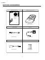
SUPPLIED ACCESSORIES
Wireless Remote Control (×1)
LC-15A2U
FRANÇAIS
ENGLISH
Operation Manual (×1)
LCD COLOR TELEVISION
TÉLÉVISION COULEUR À
ÉCRAN À CRISTAUX
LIQUIDES (LCD)
OPERATION MANUAL
MODE D’EMPLOI
Printed on post-consumer recycled paper.
Imprimé sur du papier recyclé.
PRINTED IN JAPAN
IMPRIMÉ AU JAPON
TINS-6961CEZZ
0C. T2444-A
TINS-6961CEZZ
RRMCG1559CESA
Antenna Cable
AC Cord
QCNW-5730CEZZ
QACCD3088CEZZ
AC Adapter (×1)
Size AAA Dry Battery (×2)
UADP-0212CEZZ
UBATU0026GEZZ
6
LC-15A2U
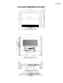
OUTLINE DIMENSION FIGURE
1-3/4 (45.3)
1-3/16 (30.3) 1/16 (1.5)
9-3/32 (231.1)
12-3/32 (310.6)
3/64 (1.5)
13-3/8 (341.4)
5-7/16 (138.7)
14-1/8 (359.0)
14-1/16 (357.0)
12-3/32 (307.4)
ø 8-1/16 (205.0)
1/2
(12)
1/2 1/2 1/2 1/2
(12) (12) (12) (12)
4-1/2 (114.5)
1-13/16 (46.4)
1-31/28 (26.0)
2-5/32 (66.0)
1/8 (3.0)
9/16 9/16 9/16 9/16 9/16 9/16 9/16 9/16 9/16 1/2 9/16
(14.0) (14.0) (14.0) (14.0) (14.0) (14.0) (14.0) (14.0) (14.0) (13.0) (14.0)
1/8 (3.0)
1/32 (4.5)
1-3/8
(35.5)
7
7/64 (2.75)
4-7/8 (124.1)
4-3/4 (121.1)
6-5/32 (156.4)
(1-31/32) ((50.0))
13-11/32 (339.2)
LC-15A2U
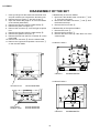
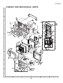
DISASSEMBLY OF THE SET
1. Insert your finger into the center of the terminal cover
and pull it toward you to detach the terminal cover.
2. Remove the four screws 1 and one screw 2.
3. Open the cabinet B by approx. 45˚ from the bottom
of the cabinet (stand side).
4. Remove the lead wire from the cable clamp 3.
5. Remove the power connector 4.
6. Remove the connector 5 from the light reception
unit.
7. Remove the lead wire from the cable clamp 6.
8. Remove the speaker connector 7.
9. Remove the FFC from the FFC connector 8 on the
main PWB.
10. Remove the connector 9 from the switch PWB.
11. Remove the right and left speaker connectors 0
on the terminal PWB.
<<Disassembly of the main PWB>>
1. Disconnect the flexible cable connectors q and
w from the LCD panel.
2. Disconnect the cable connectors e and r from
the fluorescent lamp.
3. Remove the four screws t.
<<Disassembly of the terminal PWB>>
1. Remove the cover u.
2. Remove the five screws y.
3. Remove the two screws i. Take them out of the
cabinet holes.
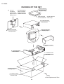
<<Cabinet A side>>
Cabinet A
CCABA2402CE02
<<Cabinet B side>>
Terminal Cover
GCOVA1858CEKA
Hinge Cover
Rotation Cover
GCOVA1853CESA
GCOVA1854CESA
Cabinet B
8
CCABB2288CE01
LC-15A2U
ADJUSTING PROCEDURE OF EACH SECTION
The best adjustment is made before shipping. If any position deviation is found or after part replace is performed, adjust
as follows.
1. Preparation for Adjustments
(1)Use the exclusive-use AC adapter or stable DC power supply.
AC adapter: UADP-0212CEZZ
DC power supply: 12 ± 0.5V
2. Special mode setting procedure
(1)After initialization of E2PROM the mode is changed to the adjustment mode.
[Procedure]
Connect TP2001 and TP2002 to GND, and turn on the power.
[Description]
• The initialization of microcomputer is as follows.
• AV position, DAC data, G/A data, sound processor data, and video chroma data adjustment values are taken as
defaults.
(2)Adjustment mode
[Procedure]
Short-circuit TP2001 to GND, and turn on the power.
Or short-circuit TP2002 to GND, and turn on the power.
Or holding down the [TV/VIDEO] key and [MENU] key, turn on the main power, and simultaneously press the
(inspection process) [CH "] key and [VOL– ] key to change the mode to the adjustment mode.
[Description]
The manual adjustment or adjustment through communication with the automatic machine is performed.
(3)Inspection mode
[Procedure]
Holding down the [TV/VIDEO] key and [MENU] key, turn on the power.
[Description]
• In the ordinary menu select “VIDEO ADJUST” with the [CH] key, and decide with the [VOL] key. Then select
“PICTURE”, “TINT (only NTSC)”, “COLOR”, “BLACK LEVEL”, “SHARPNESS”, “RED-BLUE”, “GREEN” and “COLOR
SYSTEM” with the [CH] key, and decide with the [VOL] key. After that, adjust values with the [VOL] key.
• VOLUME, PICTURE, TINT (only NTSC), COLOR, BLACK LEVEL, SHARPNESS, RED-BLUE, GREEN change as
follows.
ûMin.Û ûCenterÛ ûMax.Û
(4)Shipping setting mode
[Procedure]
Holding down the [TV/VIDEO] key and [MENU] key, turn on the main power, and simultaneously press the (inspection
process) [CH '] key and [VOL+] key to change the mode to the adjustment mode.
[Description]
User adjustment and other values are taken as defaults.
If TV is indicated as SETTING COMPLETE, setting has been completed.
9
LC-15A2U
3. Cancel of special mode
Turn off the main unit power.
4. Adjustments
Adjustment
1
B+ Adjustment
(If E2PROM is replaced)
(IC2004)
Adjusting conditions
1. Connect the DC voltmeter to
pin 49 of SC401.
Adjusting method
1. Adjust the "B+ Adj" value to
5.0V±0.02V with [VOL+] or [VOL-]
2. Go to the adjustment mode.
Key.
* The color of "B+ Adj" must be yellow.
2
Model setup
1. Go to the adjustment mode.
2
1. Select "MODEL" with [MENU] key
(If E PROM is replaced)
and adjust to "A2U" with [VOL+]
(IC2004)
or [VOL-] key.
* The color of "MODEL" must be yellow.
3
Counter-bias adjustment
1. Receive a B/W channel.
2. Go to the adjustment mode.
3. Select the "COM BIAS" with
[MENU] key.
1. Adjust "COM BIAS" to the darkest
screen with [VOL+] and [VOL-] key.
* The color of "COM BIAS" must be
yellow.
5. Shipping setting list
Channel ............................................................................................................................................... 2ch
Air/Cable ............................................................................................................................................. Air
Skip Data_CATV ................................................................................................................................. All Skip
Skip Data_AIR .................................................................................................................................... All Skip
Volume ................................................................................................................................................ 20
Picture ................................................................................................................................................. 30
Tint ...................................................................................................................................................... 0
Color ................................................................................................................................................... 0
Black Level ......................................................................................................................................... 0
SHARP ................................................................................................................................................ 0
RED-BLUE .......................................................................................................................................... 0
GREEN ............................................................................................................................................... 0
TV Color System ................................................................................................................................. N358
AV Color System ................................................................................................................................ Auto
Language ............................................................................................................................................ English
Blue Screen ........................................................................................................................................ Off
EZ Setup Auto Start ............................................................................................................................ On
Sleep Timer ........................................................................................................................................ None
MTS .................................................................................................................................................... Stereo
Brightness ........................................................................................................................................... Bright
Auto Power Off ................................................................................................................................... Off
Upside ................................................................................................................................................. Normal
Right/Left ............................................................................................................................................ Normal
AV1 ..................................................................................................................................................... Normal
AV2 IN/OUT ........................................................................................................................................ In
Closed Caption (Mode) ...................................................................................................................... OFF
(Data) ....................................................................................................................... CH1
V Chip block
(MPAA) ..................................................................................................................... None
(TV Guideline) .......................................................................................................... None
(Block Content) ........................................................................................................ All Unblock
(Status) ..................................................................................................................... Off
(Input Secret No.) ..................................................................................................... Clear
10
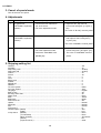
No TV and
VIDEO 1
output
No
Check LCD
panel voltage
and
waveform.
Yes
Are inputs
and outputs No
of IC1201 as
specified?
Yes
Are inputs
and outputs
of IC802 as
specified?
Check
IC1201 and
its peripheral
parts.
Check IC802
and its
peripheral
parts.
No
Is input at Pin No
(73) of IC802
as specified?
Yes
Are inputs
and outputs
of IC402 as
specified?
Check IC802,
AV1 line and
their
peripheral
parts.
Check IC402
and its
peripheral
parts.
Check all the settings on the microprocessor’s adjust process menu.
No picture
at all
No picture
No
11
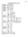
Check IC402
and its
peripheral
parts.
Yes
Are Pins (2)
No
and (4) of
IC402 at “H”
and “L”
respectively?
Yes
Is input at Pin No
(1) of IC402
as specified?
Yes
Is output at
Pin (19) of
tuner as
specified?
Yes
Are voltages
No
at Pins (6),
(7) and (9) of
tuner as
specified?
No TV
output
Check the
line in
question.
Yes
Are Pins (65)
and (66) of
IC2001 at “H”
and “L”
respectively?
Check the
line in
question.
Check the
tuner and its
peripheral
parts.
Check the
power line.
Check IC402
and its
peripheral
parts.
Yes
Are Pins (2)
No
and (4) of
IC402 both at
“L”?
Yes
Is input at Pin No
(1) of IC402
as specified?
No VIDEO
1 output
Check the
line in
question.
Yes
Are Pins (65)
and (66) of
IC2001 both
at “L”?
Check the
line in
question.
Check J3409,
AV2 line and
their
peripheral
parts.
No
Is input at Pin
(74) of IC802
as specified?
No VIDEO
2 output
Check
SC3301, SY
line, SC line
and
peripheral
parts.
No
Are inputs at
Pins (71) and
(72) of IC802
as specified?
No S
VIDEO
output
Check J3404,
J3405, J3406,
DVD-Y line,
CB line, CR
line and
peripheral
parts.
No
Is input at
Pins (4), (5),
(6) and (75)
of IC802 as
specified?
No
COMPONENT
output
LC-15A2U
TROUBLE SHOOTING TABLE
12
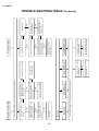
No
No
No VIDEO color
Check J3701, its peripheral
parts and connection cable.
Yes
Is any of T701’s primary side, No
Q701, Q710 and S4701
short-circuited?
Yes
Disconnect F3701 and
F3702. Is the load side
short-circuited?
Check all the settings on the microprocessor’s adjust process menu.
No TV color
No color
Check the secondary-side
load of T701.
Yes
Are the oscillation waveform
at T701’s primary side as
specified?
No
Are secondary outputs
(+38V, +16V, +9V, +5V, -8V)
of T701 as specified?
Yes
Do F3701 and F3702
function?
Check all the settings on the microprocessor’s adjust process menu.
No picture and sound
Check SC3301, SC line and
peripheral parts.
No
Is input at Pin (71) of IC802
as specified?
No S-VIDEO color
Check S4701 and
connection cable.
Replace F3701 and F3702.
No
No
Check J3404, J3405, CB line,
CR line and peripheral parts.
No
Is input at Pins (4) and (6) of
IC802 as specified?
No COMPONENT color
Replace the fluorescent lamp
and check the oscillation
waveform again.
Yes
Are the oscillation waveforms No
at the primary side of T751
and T752 as specified?
Yes
Is Pin (34) of IC1201 at “H”?
Yes
Does F3751 function?
Fluorescent lamp
Check Q751, Q752, T751,
T752, Q753 and their
peripheral parts.
Yes
Check the line, IC1201 and
its peripheral parts.
Yes
Replace F3751.
LC-15A2U
TROUBLE SHOOTING TABLE (Continued)
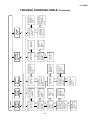
No sound
from rear
speakers
No sound
from
headphone
13
Check the
speakers and
their peripheral
parts.
Yes
Are inputs at
Pins (5) and (8)
as well as
outputs at Pins
(2) and (11), all
of IC301, as
specified?
Yes
Are inputs and
outputs of
IC303 as
specified?
Yes
Are outputs at
Pins (1) and (7)
of IC903 as
specified?
Yes
Is Pin (53) of
IC2001 at “L”?
No
No
No
No
Check the line
in question,
IC303 and its
peripheral
parts.
Check IC303
and its
peripheral
parts.
Check IC901,
IC903 and their
peripheral
parts.
Muting effect is
on. Check the
FSMU line.
Check the
speaker and its
peripheral
parts.
Yes
Are input at Pin
(5) as well as
output at Pin
(2) of IC302, as
specified?
Yes
Is Pin (54) of
IC2001 at “L”?
Check the
headphone and
its peripheral
parts.
Yes
Is Pin (55) of
IC2001 at “L”?
No
No
No
Check all the settings on the microprocessor’s adjust process menu.
No sound
from front
speakers
No sound
Check the line
IC901, IC303
and their
peripheral
parts.
Muting effect is
on. Check the
FSMU line.
Check Q306,
J3410 and their
peripheral
parts.
Check the line
in question.
Yes
Are outputs at
Pins (1) and (7)
of IC902 as
specified?
Yes
Is Pin (52) of
IC2001 at “L”?
No sound
from output
line
No
No
Check IC902
and its
peripheral
parts.
Check the
LMUTE line.
Is input at Pin
(60) of IC901
as specified?
Yes
Is output at Pin
(16) of tuner as
specified?
TV sound
failure
No
No
Check IC901,
Q3301, Q3204,
Q3205 and
their peripheral
parts.
Check the
tuner and its
peripheral
parts.
LC-15A2U
TROUBLE SHOOTING TABLE (Continued)
LC-15A2U
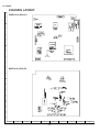
CHASSIS LAYOUT
MAIN Unit (Side-A)
J
I
H
G
F
MAIN Unit (Side-B)
E
D
C
B
A
1
2
3
4
5
6
14
7
8
9
10
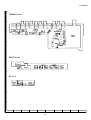
LC-15A2U
J
TERMINAL Unit
I
H
G
F
SWITCH Unit
E
D
R/C Unit
C
B
A
1
2
3
4
5
6
15
7
8
9
10
LC-15A2U
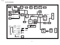
LC-15A2U
BLOCK DIAGRAM
16-17
LC-15A2U
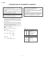
DESCRIPTION OF SCHEMATIC DIAGRAM
IMPORTANT SAFETY NOTICE:
PARTS MARKED WITH " å "(
) ARE
INPORTANT FOR MAINTAINING THE SAFETY OF
THE SET.
BE SURE TO REPLACE THESE PARTS WITH
SPECIFIED ONES FORMAINTAINING THE SAFETY
AND PERFORMANCE OF THE SET.
AVIS DE SECURITE IMPORTANT:
LES PIECES MARQUEES " å" (
) SONT
IMPORTANTES POUR MAINTENIR LA SECURITE
DE L'APPAREIL.
NE REMPLACER CES PIECES QUE PAR DES
PIECES DONT LE NUMERO EST SPECIFIE POUR
MAINTENIR LA SECURITE ET PROTEGER LE
BON FONCTIONNEMENT DE L'APPAREIL.
CAUTION:
This circuit diagram is original one, therefore there
may be a slight difference from yours.
1. When the exclusive-use AC adapter is used, the color
bar signal of color bar generator for service is input
to get the normal screen. When the audio is
minimized, the voltage value is measured with the
20 kΩ/V tester.
2. When the exclusive-use AC adapter is used, the color
density, lightness and color hue are set to the center
position, and the signal of color bar generator for
service is observed to get waveform.
The wave form test point is indicated with the mark
( ) in the wiring diagram.
[Item]
3. Indication of resistors and capacitors
[Resistors]
Unit
Nonindication
C
S
N
W
T
: Nonindication … Ω, K…kΩ,
M … MΩ
Error : Nonindication …
J…
F…
D…
±10%
±5%
±1%
±0.5%
[Capacitor]
Unit
Nonndication
ML
PF
film capacitor
TA
Styrol capacitor
: Nonindication or µ … µF,
P or p … pF
18
Resistors
Carbon-film resistor
Solid resistor
Metal-oxide-film resistor
Metal-film resistor
Cement resistor
Special resistor
Capacitors
Ceramic capacitor
Mylar capacitor
Polypropylene
Tantalum capacitor
LC-15A2U
Ë SWITCH and R/C Unit
J
I
H
G
F
E
D
C
B
A
1
2
3
4
5
6
19
7
8
9
10
LC-15A2U
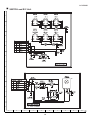
LC-15A2U
Ë MAIN Unit -1/2
å AND SHADED COMPONENTS=SAFETY RELATED PARTS
J
I
H
G
F
E
D
C
B
A
1
2
3
4
5
6
7
8
9
10
11
20-21
12
13
14
15
16
17
18
19
20
LC-15A2U
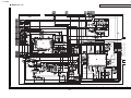
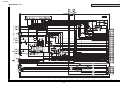
LC-15A2U
Ë MAIN Unit -2/2
å AND SHADED COMPONENTS=SAFETY RELATED PARTS
J
I
H
G
F
E
D
C
B
A
1
2
3
4
5
6
7
8
9
10
11
22-23
12
13
14
15
16
17
18
19
20
LC-15A2U
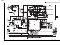
LC-15A2U
Ë TERMINAL Unit
å AND SHADED COMPONENTS=SAFETY RELATED PARTS
J
I
H
G
F
E
D
C
B
A
1
2
3
4
5
6
7
8
9
10
11
24-25
12
13
14
15
16
17
18
19
20
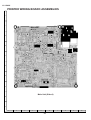
LC-15A2U
PRINTED WIRING BOARD ASSEMBLIES
J
I
H
G
F
E
D
C
Main Unit (Side-A)
B
A
1
2
3
4
5
6
26
7
8
9
10
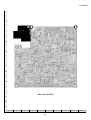
LC-15A2U
J
I
H
G
F
E
D
C
Main Unit (Side-B)
B
A
1
2
3
4
5
6
27
7
8
9
10
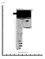
LC-15A2U
J
I
H
G
F
E
D
C
B
Terminal Unit (Side-A)
A
1
2
3
4
5
6
28
7
8
9
10
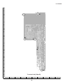
LC-15A2U
J
I
H
G
F
E
D
C
B
Terminal Unit (Side-B)
A
1
2
3
4
5
6
29
7
8
9
10
LC-15A2U
J
I
Switch Unit (Side-A)
H
G
Switch Unit (Side-B)
F
E
D
R/C Unit (Side-A)
C
R/C Unit (Side-B)
B
A
1
2
3
4
5
6
30
7
8
9
10
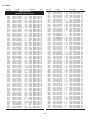
LC-15A2U
Ref. No.
★ LIST
Description
PARTS
Part No.
Code
Ref. No.
★
Description
LISTE DES
PIECES
Part No.
Code
PARTS REPLACEMENT
CHANGE DES PIECES
Replacement parts which have these special safety characteristics identified in this manual: electrical components having
such features are identified by “ å ” and shaded area in the
Replacement Parts Lists and schematic diagrams.
The use of a substitute replacement part which does not have
the same safety characteristics as the factory recommended
replacement parts shown in this service manual may create
shock, fire or other hazards.
Les pièces de rechange qui présentent ces caractéristiques spéciales
de sécurité, sont identifiées dans ce manuel : les pièces électriques
qui présentent ces particularités, sont repérée par la marque "å" et
sont hachurées dans les listes de pièces et dans les diagrammes sch
ématiques.
La substitution d'une pièce de rechange par une autre qui ne présente
pas les mêmes caractéristiques de sécurité que la pièce recommand
ée par l'usine et repérée dans ce manuel de service, peut provoquer
une électrocution, un incendie ou tout autre sinistre.
“ HOW TO ORDER REPLACEMENT PARTS”
“ COMMENT COMMANDER LES PIECES DE RECHANGE”
To have your order filled promptly and correctly, please furnish
the following informations.
1. MODEL NUMBER
3. PART NO.
in USA :
Pour que votre commande soit rapidement et correctement remplie,
veuillez fournir les renseignements suivants.
2. REF. NO.
4. DESCRIPTION
1. NUMERO DU MODELE
3. NO. DE PIECE
Contact your nearest SHARP Parts Distributor to order. For
location of SHARP Parts Distributor, Please call Toll-Free:
1-800-BE SHARP
in CANADA : Contact SHARP Electronics of Canada Limited Phone
(416) 890-2100
MARK★: SPARE PARTS-DELIVERY SECTION
Ref. No.
★
Part No.
Description
MARK★: SPARE PARTS-DELIVERY SECTION
Code
Ref. No.
J LCD Module Unit
KLMP-0098CEZZ
J Lamp Unit
BA
PRINTED WIRING BOARD ASSEMBLIES
(NOT REPLACEMENT ITEM)
DUNTKA077FE09
DUNTKA146DE01
DUNTKA147DE01
DUNTKA148DE01
–
–
–
–
Main PWB Unit
Terminal PWB Unit
Switch PWB Unit
R/C PWB Unit
★
Description
Code
INTEGRATED CIRCUITS
DQ
LAMP UNIT
å
Part No.
DUNTKA077FE09
MAIN PWB UNIT
LCD MODULE UNIT
RLCDT0058CEZZ
2. NO. DE REF
4. DESCRIPTION
—
—
—
—
IC201
IC301
IC302
IC303
IC402
IC701
IC702
IC704
IC802
IC901
IC902
IC903
IC1101
IC1102
IC1103
IC1104
IC1105
IC1106
IC1107
IC1108
IC1109
IC1110
IC1201
IC1202
IC2001
IC2002
IC2003
IC2004
IC2005
VHiNJM2147M-1
VHiLA4227//-1
VHiLA4227//-1
VHiNJM2283F-1
VHiNJM2235M-1
VHiAN8005M/-1
VHiNJM2377M-1
VHiBA033FP/-1
VHiVPC3230D-1
RH-iX3370CEZZ
VHiNJM4560M-1
VHiNJM4560M-1
VHiMB8346BV-1
VHiNJM4565V-1
VHiNJM4565V-1
VHiNJM4565V-1
VHiBU4053V/-1
VHiNJM4580V-1
VHiNJM4580V-1
VHiNJM4580V-1
VHiNJM353M/-1
VHiBU4053V/-1
RH-iX3378CEZZ
VHiPD485505-2
RH-iX3448CEZZ
VHiPST529DM-1
VHiTC4W66F/-1
VHiBR24C08F-1
VHiBA7046F/-1
Q201
Q202
Q203
Q204
Q302
Q303
Q304
Q305
Q306
VS2SC2712Y/-1
VS2SC2712Y/-1
VSFMY3/////-1
VS2SC2712Y/-1
VS2SA1162Y/-1
VSDTC314TK/-1
VSDTC314TK/-1
VSDTC314TK/-1
VSDTC144EE/-1
J
J
J
J
J
J
J
J
J
J
J
J
J
J
J
J
J
J
J
J
J
J
J
J
J
J
J
J
J
NJM2147M
AF
LA4227, Audio Amplifer
AG
LA4227
AG
NJM2283M, L/R Reverse AF
NJM2235M, TV/AV1 SelectionAE
AN8005M
AD
NJM2377M, PWM
AK
BA033FP
AG
VPC3230D, VPC
BG
IX3370CE, MSP
AZ
NJM4560M, Buffer
AG
NJM4560M, LPF
AG
MB8346BV, DAC
AN
NJM4565V
AF
NJM4565V
AF
NJM4565V
AF
BU4053V
AE
NJM4580V
AE
NJM4580V
AE
NJM4580V
AE
NJM353M, COMMON
AG
BU4053V
AE
IX3378CE, LCD Controller AY
PD485505
AY
IX3448CEN, Micon
BA
PST529DM, Reset
AE
TC4W66F
AE
BR24C08F, E2PROM
AF
BA7046F
AF
TRANSISTORS
31
J
J
J
J
J
J
J
J
J
2SC2712Y
2SC2712Y
FMY3
2SC2712Y
2SA1162Y
DTC314TK
DTC314TK
DTC314TK
DTC144EE
AB
AB
AB
AB
AB
AC
AC
AC
AA
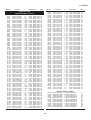
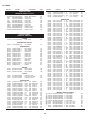
LC-15A2U
Ref. No.
★
Part No.
Description
Code
DUNTKA077FE09
MAIN PWB UNIT(Continued)
Q308
Q701
Q702
Q703
Q707
Q708
Q709
Q710
Q751
Q752
Q753
Q754
Q757
Q1101
Q1102
Q1201
Q2003
Q2004
Q2005
Q2006
VSDTC144EE/-1
VS2SA1162Y/-1
VS2SK2503//-1
VS2SC2712Y/-1
VSDTC144EE/-1
VSFMMT718//-1
VSDTC144EE/-1
VS2SA1162Y/-1
VSFZT1053A/-1
VSFZT1053A/-1
VS2SA1162Y/-1
VSDTC114YE/-1
VSUPA606T//-1
VS2SA1729S/-1
VS2SC4520S/-1
VSDTC144EE/-1
VS2SC2712Y/-1
VSDTC144EE/-1
VSDTA144EE/-1
VSDTC144EE/-1
J
J
J
J
J
J
J
J
J
J
J
J
J
J
J
J
J
J
J
J
DTC144EE
2SA1162Y
2SK2503
2SC2712Y
DTC144EE
FMMT718
DTC144EE
2SA1162Y
FZT1053A
FZT1053A
2SA1162Y
DTC114YE
UPA606T
2SA1729S
2SC4520S
DTC144EE
2SC2712Y
DTC144EE
DTA144EE
DTC144EE
D201
D702
D703
D704
D705
D706
D707
D709
D710
D712
D753
D754
D1101
D1201
D1202
VHDDAN222//-1
VHDSFPB56//2E
VHD1SS250//1E
VHD1SS250//1E
VHDDAN222//-1
VHDSFPB74//2E
VHDDAN222//-1
VHDDAN222//-1
VHDDAN222//-1
VHDDAN222//-1
VHDiMN10///-1
VHDiMN10///-1
VHD1SS250//1E
VHDDAN222//-1
RH-EX0227CEZZ
X801
X901
RCRSC0012CEZZ J Crystal, CRSC0012CE
RCRSB0250GEZZ J Crystal, CRSB0250GE
X2002
RFiLA0107CEZZ
L701
L705
L706
L751
L752
L801
L802
L803
L804
L805
L806
L807
L901
L902
L1202
L1203
L1204
L1205
RCiLC0130CEZZ
RCiLC0057CEZZ
RCiLC0130CEZZ
RCiLC0107CEZZ
RCiLC0107CEZZ
VP-1M3R3JR93N
VP-1M3R3JR93N
VP-1M3R3JR93N
RCiLC0055CEZZ
RCiLC0055CEZZ
VP-1M4R7J1R2N
VP-1M4R7J1R2N
VP-1M4R7J1R2N
VP-1M101J7R7N
VP-1M470J5R4N
VP-1M220J2R9N
VP-1M220J2R9N
VP-1M220J2R9N
DAN222
SFPB56
1SS250
1SS250
DAN222
SFPB74
DAN222
DAN222
DAN222
DAN222
IMN10
IMN10
1SS250
DAN222
Zener Diode
AA
AB
AE
AB
AA
AE
AA
AB
AG
AG
AB
AB
AD
AE
AF
AA
AB
AA
AA
AA
AA
AC
AB
AB
AA
AD
AA
AA
AA
AA
AB
AB
AB
AA
AB
PACKAGED CIRCUITS
AH
AG
FILTER
J Filter, FiLA0107CE
AD
COILS
J
J
J
J
J
J
J
J
J
J
J
J
J
J
J
J
J
J
Coil, CiLC0130CE
Coil, CiLC0057CE
Coil, CiLC0130CE
Coil, CiLC0107CE
Coil, CiLC0107CE
Peaking, 3.3µH
Peaking, 3.3µH
Peaking, 3.3µH
Coil, CiLC0055CE
Coil, CiLC0055CE
Peaking, 4.7µH
Peaking, 4.7µH
Peaking, 4.7µH
Peaking, 100µH
Peaking, 47µH
Peaking, 22µH
Peaking, 22µH
Peaking, 22µH
AG
AD
AG
AF
AF
AB
AB
AB
AD
AD
AB
AB
AB
AC
AC
AC
AC
AC
TRANSFORMERS
å T701
å T751
å T752
RTRNZ0778CEZZ
RTRNZ0777CEZZ
RTRNZ0777CEZZ
J Transformer
J Transformer
J Transformer
Part No.
C201
C202
C203
C204
C205
C206
C301
C302
C303
C304
C305
C306
C307
C308
C309
C310
C311
C312
C313
C314
C316
C317
C318
C319
C320
C321
C322
C323
C324
C325
C326
C327
C328
C329
C330
C403
C404
C406
C408
C409
C411
C701
C702
C703
C704
C706
C707
C708
C710
C711
C712
C713
C716
C719
C721
C722
C728
C729
C731
C733
C734
C735
C736
C737
C738
C740
C741
C746
C747
C748
C749
C751
C752
C757
VCKYTV1HF104Z
VCKYCY1EF104Z
RC-KZ1025CEZZ
RC-KZ1025CEZZ
VCKYCY1EF104Z
VCKYCY1HF103Z
VCEAPF1CN106M
VCEAPF1CN107M
VCKYCY1EF104Z
VCEAPF1CN476M
VCKYCY1HB102K
VCEAPW1CN477M
VCEAPF1HN225M
VCEAPF1HN225M
VCKYCY1HB102K
VCEAPF1CN476M
VCKYCY1EF104Z
VCEAPF1CN107M
VCKYTV1CF105Z
VCEA4U1CN228M
VCKYCY1EF104Z
VCEAPF1HN105M
VCEAPF1HN105M
VCEAPF0JN226M
VCEAPF0JN226M
VCEAPF1CN106M
VCEAPF1CN107M
VCKYCY1EF104Z
VCEAPF1CN107M
VCKYCY1CB273K
VCEAPW1CN477M
VCEAPF1HN105M
RC-EZ1274CEZZ
VCKYTV1CF105Z
VCEAPF1HN225M
VCKYTV1AB105K
VCKYTV1AB105K
VCKYCY1EF104Z
VCCCCY1HH331J
VCCCCY1HH331J
VCCCCY1HH331J
VCCCCY1HH471J
VCKYTV1CF105Z
VCEAPF1CN226M
VCKYTV1CF105Z
VCKYCY1HB562K
VCKYCY1CF334Z
VCEAPF0JN226M
VCKYTV1CF105Z
VCKYCY1EB103K
VCEAPT1CN226M
RC-EZ1176CEZZ
VCKYTV1CF105Z
RC-EZ0420CEZZ
VCEASD1HN336M
VCKYTV1HF104Z
VCKYTV1HF104Z
VCKYTV1CF105Z
VCCCCY1HH181J
RC-EZ0538CEZZ
VCKYTV1CF105Z
RC-EZ0416CEZZ
RC-EZ0416CEZZ
RC-EZ1339CEZZ
RC-KZ1025CEZZ
VCEAPF1EN475M
VCKYTV1CF105Z
VCKYCY1EF104Z
VCKYTV1HB562K
RC-EZ1339CEZZ
RC-EZ1177CEZZ
VCEA4U1CN228M
RC-FZ0174CEZZ
VCKYCY1CB823K
Description
Code
CAPACITORS
DIODES
J
J
J
J
J
J
J
J
J
J
J
J
J
J
J
★
Ref. No.
AM
AM
AM
32
J
J
J
J
J
J
J
J
J
J
J
J
J
J
J
J
J
J
J
J
J
J
J
J
J
J
J
J
J
J
J
J
J
J
J
J
J
J
J
J
J
J
J
J
J
J
J
J
J
J
J
J
J
J
J
J
J
J
J
J
J
J
J
J
J
J
J
J
J
J
J
J
J
J
0.1
0.1
1
1
0.1
0.01
10
100
0.1
47
1000p
470
2.2
2.2
1000p
47
0.1
100
1
2200
0.1
1
1
22
22
10
100
0.1
100
0.027
470
1
1000
1
2.2
1
1
0.1
330p
330p
330p
470p
1
22
1
5600p
0.33
22
1
0.01
22
100
1
100
33
0.1
0.1
1
180p
330
1
330
330
220
1
4.7
1
0.1
5600p
220
150
2200
0.12
0.082
50V Ceramic
25V Ceramic
10V Ceramic
10V Ceramic
25V Ceramic
50V Ceramic
16V Electrolytic
16V Electrolytic
25V Ceramic
16V Electrolytic
50V Ceramic
16V Electrolytic
50V Electrolytic
50V Electrolytic
50V Ceramic
16V Electrolytic
25V Ceramic
16V Electrolytic
16V Ceramic
16V Electrolytic
25V Ceramic
50V Electrolytic
50V Electrolytic
6.3V Electrolytic
6.3V Electrolytic
16V Electrolytic
16V Electrolytic
25V Ceramic
16V Electrolytic
16V Ceramic
16V Electrolytic
50V Electrolytic
16V Electrolytic
16V Ceramic
50V Electrolytic
10V Ceramic
10V Ceramic
25V Ceramic
50V Ceramic
50V Ceramic
50V Ceramic
50V Ceramic
16V Ceramic
16V Electrolytic
16V Ceramic
50V Ceramic
16V Ceramic
6.3V Electrolytic
16V Ceramic
25V Ceramic
16V Electrolytic
16V Electrolytic
16V Ceramic
25V Electrolytic
50V Electrolytic
50V Ceramic
50V Ceramic
16V Ceramic
50V Ceramic
16V Electrolytic
16V Ceramic
6.3V Electrolytic
6.3V Electrolytic
16V Electrolytic
10V Ceramic
25V Electrolytic
16V Ceramic
25V Ceramic
50V Ceramic
16V Electrolytic
6.3V Electrolytic
16V Electrolytic
100V Ceramic
16V Ceramic
AA
AA
AB
AB
AA
AA
AD
AD
AA
AD
AA
AE
AD
AD
AA
AD
AA
AD
AB
AE
AA
AD
AD
AD
AD
AD
AD
AA
AD
AA
AE
AD
AD
AB
AD
AD
AD
AA
AA
AA
AA
AA
AB
AD
AB
AA
AA
AD
AB
AA
AC
AK
AB
AE
AD
AA
AA
AB
AA
AE
AB
AD
AD
AD
AB
AC
AB
AA
AA
AD
AH
AE
AG
AH
LC-15A2U
Ref. No.
Part No.
★
Description
Code
DUNTKA077FE09
MAIN PWB UNIT(Continued)
C759
C762
C764
C765
C801
C802
C803
C804
C805
C806
C807
C808
C809
C810
C811
C812
C813
C814
C815
C816
C817
C818
C819
C820
C821
C822
C825
C826
C827
C830
C831
C836
C839
C840
C841
C842
C844
C848
C874
C875
C876
C878
C879
C902
C905
C906
C909
C910
C911
C912
C913
C914
C915
C916
C919
C920
C921
C922
C923
C924
C925
C927
C928
C929
C930
C931
C932
C933
C935
C937
C938
C939
VCEAPF0JN107M
RC-FZ0174CEZZ
VCKYTV1CF105Z
VCKYTV1CF105Z
VCEAPF1CN106M
VCKYCY1EF104Z
VCCCCY1HH7R0D
VCCCCY1HH7R0D
RC-KZ1025CEZZ
RC-KZ1025CEZZ
VCKYCY1HB331K
VCKYCY1HB331K
VCEAPK1CN107M
VCKYCY1EF104Z
VCKYCY1HB331K
RC-KZ1025CEZZ
RC-KZ1025CEZZ
VCKYCY1HB102K
VCKYTV1CF684Z
VCKYTV1CF684Z
VCKYTV1CF684Z
RC-KZ1025CEZZ
RC-KZ1025CEZZ
VCKYCY1EF104Z
VCEAPW1CN477M
RC-KZ1025CEZZ
RC-KZ1025CEZZ
VCKYCY1CF224Z
VCKYCY1CF224Z
VCEAPF0GW107M
VCKYCY1EF104Z
VCE9PF1CN475M
VCKYCY1CF224Z
VCKYCY1CF224Z
VCKYCY1CF224Z
VCEAPF0GW107M
VCKYCY1EF104Z
VCEAPF0JW107M
RC-KZ1025CEZZ
RC-KZ1025CEZZ
VCEAPF0GW107M
RC-KZ1025CEZZ
VCKYTV1CF684Z
VCKYCY1EF104Z
VCEAPF1CW106M
VCEAPF1CW106M
VCKYCY1HB682K
VCKYCY1HB682K
VCEAPF1CW106M
VCEAPF1CW106M
VCKYCY1EF104Z
RC-EZ0417CEZZ
VCEAPF0JW336M
VCKYCY1EF104Z
RC-KZ1025CEZZ
RC-KZ1025CEZZ
RC-KZ1025CEZZ
RC-KZ1025CEZZ
VCKYCY1EF104Z
VCEAPF1CW106M
RC-KZ1025CEZZ
VCCCCY1HH560J
VCCCCY1HH560J
VCCCCY1HH560J
VCCCCY1HH5R0C
VCCCCY1HH5R0C
VCKYCY1EF104Z
RC-EZ0417CEZZ
VCEAPF1CW226M
RC-EZ0417CEZZ
RC-EZ0417CEZZ
VCKYCY1HB561K
J
J
J
J
J
J
J
J
J
J
J
J
J
J
J
J
J
J
J
J
J
J
J
J
J
J
J
J
J
J
J
J
J
J
J
J
J
J
J
J
J
J
J
J
J
J
J
J
J
J
J
J
J
J
J
J
J
J
J
J
J
J
J
J
J
J
J
J
J
J
J
J
100
0.12
1
1
10
0.1
7p
7p
1
1
330p
330p
100
0.1
330p
1
1
1000p
0.68
0.68
0.68
1
1
0.1
470
1
1
0.22
0.22
100
0.1
4.7
0.22
0.22
0.22
100
0.1
100
1
1
100
1
0.68
0.1
10
10
6800p
6800p
10
10
0.1
150
33
0.1
1
1
1
1
0.1
10
1
56p
56p
56p
5p
5p
0.1
150
22
150
150
560p
6.3V Electrolytic
100V Ceramic
16V Ceramic
16V Ceramic
16V Electrolytic
25V Ceramic
50V Ceramic
50V Ceramic
10V Ceramic
10V Ceramic
50V Ceramic
50V Ceramic
16V Electrolytic
25V Ceramic
50V Ceramic
10V Ceramic
10V Ceramic
50V Ceramic
16V Ceramic
16V Ceramic
16V Ceramic
10V Ceramic
10V Ceramic
25V Ceramic
16V Electrolytic
10V Ceramic
10V Ceramic
16V Ceramic
16V Ceramic
4V Electrolytic
25V Ceramic
16V Electrolytic
16V Ceramic
16V Ceramic
16V Ceramic
4V Electrolytic
25V Ceramic
6.3V Electrolytic
10V Ceramic
10V Ceramic
4V Electrolytic
10V Ceramic
16V Ceramic
25V Ceramic
16V Electrolytic
16V Electrolytic
50V Ceramic
50V Ceramic
16V Electrolytic
16V Electrolytic
25V Ceramic
16V Electrolytic
6.3V Electrolytic
25V Ceramic
10V Ceramic
10V Ceramic
10V Ceramic
10V Ceramic
25V Ceramic
16V Electrolytic
10V Ceramic
50V Ceramic
50V Ceramic
50V Ceramic
50V Ceramic
50V Ceramic
25V Ceramic
16V Electrolytic
16V Electrolytic
16V Electrolytic
16V Electrolytic
50V Ceramic
Part No.
★
C940
C941
C942
C943
C944
C945
C946
C954
C955
C956
C957
C958
C961
C962
C963
C964
C1101
C1102
C1103
C1104
C1105
C1106
C1107
C1108
C1109
C1110
C1111
C1112
C1113
C1114
C1115
C1116
C1117
C1118
C1119
C1120
C1122
C1123
C1124
C1202
C1203
C1204
C1205
C1206
C1207
C1209
C1210
C1211
C1212
C1213
C1214
C1215
C1217
C1218
C2001
C2002
C2003
C2006
C2007
C2009
C2010
C2015
C2016
C2017
C2018
C2019
C2020
C2021
C2022
C2023
C2024
VCKYCY1HB152K
VCKYCY1HB152K
VCKYCY1HB561K
VCKYCY1EF104Z
VCEAPF1CW106M
VCEAPF1HW225M
VCEAPF1HW225M
VCEAPF1CW106M
VCKYTV1CF105Z
VCKYTV1CF105Z
VCEAPF1EW475M
VCEAPF1EW475M
VCKYCY1HB102K
VCKYCY1HB102K
VCKYCY1HB102K
VCKYCY1HB102K
VCKYCY1EF104Z
VCKYCY1EF104Z
VCKYCY1EF104Z
VCKYCY1EF104Z
VCKYCY1EF104Z
VCKYCY1EF104Z
VCKYCY1EF104Z
VCKYCY1EF104Z
VCKYCY1EF104Z
VCKYCY1EF104Z
VCKYCY1EF104Z
VCKYCY1EF104Z
VCKYCY1EF104Z
VCKYCY1EF104Z
VCKYCY1EF104Z
VCKYCY1EF104Z
VCCCCY1HH560J
VCKYCY1EF104Z
VCKYTV1CF105Z
VCKYTV1EF104Z
VCKYTV1CF105Z
VCKYCY1EF104Z
VCKYCY1EF104Z
VCKYCY1EF104Z
VCKYCY1EF104Z
VCCCCY1HH220J
VCCCCY1HH220J
VCEAPF1CN107M
VCKYCY1EF104Z
VCEAPF0JW107M
VCEAPF0GW107M
VCKYCY1EF104Z
VCKYCY1EF104Z
VCEAPF0JW107M
VCEAPF0GW107M
RC-KZ1025CEZZ
VCEAPF1CW226M
VCEAPF1CN106M
VCKYCY1HB102K
VCCCCY1HH221J
VCEAPF1HW105M
VCKYCY1EF104Z
VCKYCY1EF104Z
VCKYCY1EF104Z
VCKYCY1EF104Z
VCKYCY1HB561K
VCKYCY1EF104Z
VCKYCY1EF104Z
VCCCCY1HH101J
VCKYTV1AB105K
VCKYCY1HB102K
VCEAPF1AW476M
VCKYCY1EF104Z
VCKYTV1AB105K
VCKYCY1HB222K
J
J
J
J
J
J
J
J
J
J
J
J
J
J
J
J
J
J
J
J
J
J
J
J
J
J
J
J
J
J
J
J
J
J
J
J
J
J
J
J
J
J
J
J
J
J
J
J
J
J
J
J
J
J
J
J
J
J
J
J
J
J
J
J
J
J
J
J
J
J
J
R201
R202
VRS-CY1JF102J
VRS-CY1JF103F
Ref. No.
AD
AG
AB
AB
AD
AA
AA
AA
AB
AB
AA
AA
AD
AA
AA
AB
AB
AA
AB
AB
AB
AB
AB
AA
AE
AB
AB
AA
AA
AC
AA
AD
AA
AA
AA
AC
AA
AC
AB
AB
AC
AB
AB
AA
AB
AB
AA
AA
AB
AB
AA
AD
AB
AA
AB
AB
AB
AB
AA
AB
AB
AA
AA
AA
AA
AA
AA
AD
AB
AD
AD
AA
Description
1500p
1500p
560p
0.1
10
2.2
2.2
10
1
1
4.7
4.7
1000p
1000p
1000p
1000p
0.1
0.1
0.1
0.1
0.1
0.1
0.1
0.1
0.1
0.1
0.1
0.1
0.1
0.1
0.1
0.1
56p
0.1
1
0.1
1
0.1
0.1
0.1
0.1
22p
22p
100
0.1
100
100
0.1
0.1
100
100
1
22
10
1000p
220p
1
0.1
0.1
0.1
0.1
560p
0.1
0.1
100p
1
1000p
47
0.1
1
2200p
50V
50V
50V
25V
16V
50V
50V
16V
16V
16V
25V
25V
50V
50V
50V
50V
25V
25V
25V
25V
25V
25V
25V
25V
25V
25V
25V
25V
25V
25V
25V
25V
50V
25V
16V
25V
16V
25V
25V
25V
25V
50V
50V
16V
25V
6.3V
4V
25V
25V
6.3V
4V
10V
16V
16V
50V
50V
50V
25V
25V
25V
25V
50V
25V
25V
50V
10V
50V
10V
25V
10V
50V
Ceramic
Ceramic
Ceramic
Ceramic
Electrolytic
Electrolytic
Electrolytic
Electrolytic
Ceramic
Ceramic
Electrolytic
Electrolytic
Ceramic
Ceramic
Ceramic
Ceramic
Ceramic
Ceramic
Ceramic
Ceramic
Ceramic
Ceramic
Ceramic
Ceramic
Ceramic
Ceramic
Ceramic
Ceramic
Ceramic
Ceramic
Ceramic
Ceramic
Ceramic
Ceramic
Ceramic
Ceramic
Ceramic
Ceramic
Ceramic
Ceramic
Ceramic
Ceramic
Ceramic
Electrolytic
Ceramic
Electrolytic
Electrolytic
Ceramic
Ceramic
Electrolytic
Electrolytic
Ceramic
Electrolytic
Electrolytic
Ceramic
Ceramic
Electrolytic
Ceramic
Ceramic
Ceramic
Ceramic
Ceramic
Ceramic
Ceramic
Ceramic
Ceramic
Ceramic
Electrolytic
Ceramic
Ceramic
Ceramic
Code
AA
AA
AA
AA
AB
AB
AB
AB
AB
AB
AB
AB
AA
AA
AA
AA
AA
AA
AA
AA
AA
AA
AA
AA
AA
AA
AA
AA
AA
AA
AA
AA
AA
AA
AB
AB
AB
AA
AA
AA
AA
AA
AA
AD
AA
AC
AC
AA
AA
AC
AC
AB
AB
AD
AA
AA
AB
AA
AA
AA
AA
AA
AA
AA
AA
AD
AA
AB
AA
AD
AA
RESISTORS
33
J 1k
J 10k
1/16W Metal Oxide AA
1/16W Metal Oxide AA
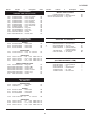
LC-15A2U
Ref. No.
Part No.
★
Description
Code
Ref. No.
AA
AA
AA
AA
AA
AA
AA
AA
AA
AA
AA
AA
AA
AA
AA
AA
AA
AA
AA
AA
AA
AA
AA
AA
AA
AA
AA
AA
AA
AA
AA
AA
AA
AA
AA
AA
AA
AA
AA
AA
AA
AA
AA
AA
AA
AA
AA
AA
AA
AA
AA
AA
AA
AA
AA
AA
AA
AA
AA
AA
AA
AA
AA
AA
AA
AA
AA
AA
AA
AA
AC
AA
R708
R709
R711
R712
R713
R715
R716
R717
R718
R719
R720
R721
R722
R723
R724
R725
R726
R729
R731
R732
R733
R734
R735
R736
R737
R738
R739
R740
R741
R742
R747
R748
R751
R752
R753
R754
R765
R766
R768
R770
R772
R774
R801
R802
R803
R804
R806
R807
R808
R809
R810
R811
R812
R813
R814
R815
R816
R819
R826
R831
R832
R833
R834
R852
R860
R861
R901
R902
R903
R905
R908
R909
R910
R913
R914
DUNTKA077FE09
MAIN PWB UNIT(Continued)
R203
R204
R205
R206
R207
R208
R209
R210
R211
R212
R213
R214
R215
R216
R217
R218
R219
R220
R301
R302
R303
R304
R305
R308
R309
R310
R311
R314
R315
R316
R317
R318
R319
R320
R321
R322
R323
R324
R327
R328
R329
R330
R401
R402
R403
R404
R405
R406
R407
R408
R409
R410
R411
R412
R413
R414
R418
R419
R420
R424
R430
R434
R435
R436
R437
R701
R702
R703
R704
R705
R706
R707
VRS-CY1JF102F
VRS-CY1JF473F
VRS-CY1JF103J
VRS-CY1JF103F
VRS-CY1JF622F
VRS-CY1JF473F
VRS-CY1JF123F
VRS-CY1JF242F
VRS-CY1JF332F
VRS-CY1JF332F
VRS-CY1JF682F
VRS-CY1JF122F
VRS-CY1JF102J
VRS-CY1JF153J
VRS-CY1JF102J
VRS-CY1JF391J
VRS-TV1JD103J
VRS-CY1JF102J
VRS-CY1JF000J
VRS-TX2HF8R2J
VRS-CY1JF331J
VRS-CY1JF331J
VRS-TX2HF8R2J
VRS-CY1JF223J
VRS-TW2ED222J
VRS-CY1JF223J
VRS-CY1JF223J
VRS-CY1JF512J
VRS-CY1JF242J
VRS-CY1JF512J
VRS-CY1JF242J
VRS-CY1JF000J
VRS-TX2HF8R2J
VRS-CY1JF150J
VRS-CY1JF242J
VRS-CY1JF472J
VRS-CY1JF472J
VRS-CY1JF472J
VRS-CY1JF000J
VRS-CY1JF104J
VRS-CY1JF104J
VRS-CY1JF104J
VRS-CY1JF101J
VRS-CY1JF000J
VRS-CY1JF682J
VRS-CY1JF682J
VRS-CY1JF101J
VRS-CY1JF101J
VRS-CY1JF103J
VRS-CY1JF103J
VRS-CY1JF101J
VRS-CY1JF101J
VRS-CY1JF101J
VRS-CY1JF101J
VRS-CY1JF101J
VRS-CY1JF101J
VRS-CY1JF101J
VRS-CY1JF000J
VRS-CY1JF101J
VRS-CY1JF101J
VRS-CA1JF562J
VRS-CY1JF105J
VRS-CY1JF105J
VRS-CY1JF105J
VRS-CY1JF000J
VRS-CY1JF1R0J
VRS-CY1JF154J
VRS-CY1JF274J
VRS-TQ2BD000J
VRS-TX2HF000J
VRS-CR3AD821J
VRS-CY1JF000J
J
J
J
J
J
J
J
J
J
J
J
J
J
J
J
J
J
J
J
J
J
J
J
J
J
J
J
J
J
J
J
J
J
J
J
J
J
J
J
J
J
J
J
J
J
J
J
J
J
J
J
J
J
J
J
J
J
J
J
J
J
J
J
J
J
J
J
J
J
J
J
J
1k
47k
10k
10k
6.2k
47k
12k
2.4k
3.3k
3.3k
6.8k
1.2k
1k
15k
1k
390
10k
1k
0
8.2
330
330
8.2
22k
2.2k
22k
22k
5.1k
2.4k
5.1k
2.4k
0
8.2
15
2.4k
4.7k
4.7k
4.7k
0
100k
100k
100k
100
0
6.8k
6.8k
100
100
10k
10k
100
100
100
100
100
100
100
0
100
100
5.6k
1M
1M
1M
0
1
150k
270k
0
0
820
0
1/16W
1/16W
1/16W
1/16W
1/16W
1/16W
1/16W
1/16W
1/16W
1/16W
1/16W
1/16W
1/16W
1/16W
1/16W
1/16W
1/16W
1/16W
1/16W
1/2W
1/16W
1/16W
1/2W
1/16W
1/4W
1/16W
1/16W
1/16W
1/16W
1/16W
1/16W
1/16W
1/2W
1/16W
1/16W
1/16W
1/16W
1/16W
1/16W
1/16W
1/16W
1/16W
1/16W
1/16W
1/16W
1/16W
1/16W
1/16W
1/16W
1/16W
1/16W
1/16W
1/16W
1/16W
1/16W
1/16W
1/16W
1/16W
1/16W
1/16W
1/16W
1/16W
1/16W
1/16W
1/16W
1/16W
1/16W
1/16W
1/8W
1/2W
1W
1/16W
Metal Oxide
Metal Oxide
Metal Oxide
Metal Oxide
Metal Oxide
Metal Oxide
Metal Oxide
Metal Oxide
Metal Oxide
Metal Oxide
Metal Oxide
Metal Oxide
Metal Oxide
Metal Oxide
Metal Oxide
Metal Oxide
Metal Oxide
Metal Oxide
Metal Oxide
Metal Oxide
Metal Oxide
Metal Oxide
Metal Oxide
Metal Oxide
Metal Oxide
Metal Oxide
Metal Oxide
Metal Oxide
Metal Oxide
Metal Oxide
Metal Oxide
Metal Oxide
Metal Oxide
Metal Oxide
Metal Oxide
Metal Oxide
Metal Oxide
Metal Oxide
Metal Oxide
Metal Oxide
Metal Oxide
Metal Oxide
Metal Oxide
Metal Oxide
Metal Oxide
Metal Oxide
Metal Oxide
Metal Oxide
Metal Oxide
Metal Oxide
Metal Oxide
Metal Oxide
Metal Oxide
Metal Oxide
Metal Oxide
Metal Oxide
Metal Oxide
Metal Oxide
Metal Oxide
Metal Oxide
Metal Oxide
Metal Oxide
Metal Oxide
Metal Oxide
Metal Oxide
Metal Oxide
Metal Oxide
Metal Oxide
Metal Oxide
Metal Oxide
Metal Oxide
Metal Oxide
34
Part No.
VRS-CY1JF272F
VRS-CY1JF123F
VRS-CY1JF184J
VRS-CY1JF683F
VRS-CY1JF133F
VRS-CY1JF000J
VRS-TX2HF000J
VRS-CY1JF152F
VRS-CY1JF274J
VRS-CY1JF563F
VRS-CY1JF473J
VRS-CY1JF103J
VRS-CY1JF105J
VRS-CY1JF682J
VRS-TQ2BD000J
VRS-CY1JF1R0J
VRS-CY1JF1R0J
VRS-TQ2BD000J
VRS-TQ2BD000J
VRS-TW2ED222J
VRS-TQ2BD683J
VRS-CY1JF393J
VRS-CY1JF223J
VRS-CY1JF1R0J
VRS-CY1JF472J
VRS-TW2ED102J
VRS-CY1JF102J
VRS-CY1JF102J
VRS-CY1JF000J
VRS-CY1JF000J
VRS-CY1JF000J
VRS-CY1JF000J
VRS-TW2ED332J
VRS-TW2ED332J
VRS-CY1JF333J
VRS-CY1JF103J
VRS-CY1JF103J
VRS-CA1JF821J
VRS-CA1JF104J
VRS-CA1JF562J
VRS-CY1JF563J
VRS-CY1JF000J
VRS-CB1JF221J
VRS-CB1JF220J
VRS-CB1JF220J
VRS-CA1JF101J
VRS-CY1JF221J
VRS-CY1JF750J
VRS-CY1JF750J
VRS-CY1JF750J
VRS-CB1JF220J
VRS-CY1JF222J
VRS-CY1JF000J
VRS-CB1JF220J
VRS-CY1JF332J
VRS-CY1JF000J
VRS-CA1JF470J
VRS-CY1JF000J
VRS-CY1JF101J
VRS-CY1JF102J
VRS-CY1JF102J
VRS-CY1JF102J
VRS-CY1JF102J
VRS-CY1JF000J
VRS-CY1JF000J
VRS-CY1JF000J
VRS-CY1JF101J
VRS-CY1JF101J
VRS-CY1JF101J
VRS-CY1JF000J
VRS-CY1JF000J
VRS-CY1JF102J
VRS-CY1JF102J
VRS-CY1JF000J
VRS-CY1JF000J
★
J
J
J
J
J
J
J
J
J
J
J
J
J
J
J
J
J
J
J
J
J
J
J
J
J
J
J
J
J
J
J
J
J
J
J
J
J
J
J
J
J
J
J
J
J
J
J
J
J
J
J
J
J
J
J
J
J
J
J
J
J
J
J
J
J
J
J
J
J
J
J
J
J
J
J
Description
2.7k
12k
180k
68k
13k
0
0
1.5k
270k
56k
47k
10k
1M
6.8k
0
1
1
0
0
2.2k
68k
39k
22k
1
4.7k
1k
1k
1k
0
0
0
0
3.3k
3.3k
33k
10k
10k
820
100k
5.6k
56k
0
220
22
22
100
220
75
75
75
22
2.2k
0
22
3.3k
0
47
0
100
1k
1k
1k
1k
0
0
0
100
100
100
0
0
1k
1k
0
0
1/16W
1/16W
1/16W
1/16W
1/16W
1/16W
1/2W
1/16W
1/16W
1/16W
1/16W
1/16W
1/16W
1/16W
1/8W
1/16W
1/16W
1/8W
1/8W
1/4W
1/8W
1/16W
1/16W
1/16W
1/16W
1/4W
1/16W
1/16W
1/16W
1/16W
1/16W
1/16W
1/4W
1/4W
1/16W
1/16W
1/16W
1/16W
1/16W
1/16W
1/16W
1/16W
1/16W
1/16W
1/16W
1/16W
1/16W
1/16W
1/16W
1/16W
1/16W
1/16W
1/16W
1/16W
1/16W
1/16W
1/16W
1/16W
1/16W
1/16W
1/16W
1/16W
1/16W
1/16W
1/16W
1/16W
1/16W
1/16W
1/16W
1/16W
1/16W
1/16W
1/16W
1/16W
1/16W
Metal Oxide
Metal Oxide
Metal Oxide
Metal Oxide
Metal Oxide
Metal Oxide
Metal Oxide
Metal Oxide
Metal Oxide
Metal Oxide
Metal Oxide
Metal Oxide
Metal Oxide
Metal Oxide
Metal Oxide
Metal Oxide
Metal Oxide
Metal Oxide
Metal Oxide
Metal Oxide
Metal Oxide
Metal Oxide
Metal Oxide
Metal Oxide
Metal Oxide
Metal Oxide
Metal Oxide
Metal Oxide
Metal Oxide
Metal Oxide
Metal Oxide
Metal Oxide
Metal Oxide
Metal Oxide
Metal Oxide
Metal Oxide
Metal Oxide
Metal Oxide
Metal Oxide
Metal Oxide
Metal Oxide
Metal Oxide
Metal Oxide
Metal Oxide
Metal Oxide
Metal Oxide
Metal Oxide
Metal Oxide
Metal Oxide
Metal Oxide
Metal Oxide
Metal Oxide
Metal Oxide
Metal Oxide
Metal Oxide
Metal Oxide
Metal Oxide
Metal Oxide
Metal Oxide
Metal Oxide
Metal Oxide
Metal Oxide
Metal Oxide
Metal Oxide
Metal Oxide
Metal Oxide
Metal Oxide
Metal Oxide
Metal Oxide
Metal Oxide
Metal Oxide
Metal Oxide
Metal Oxide
Metal Oxide
Metal Oxide
Code
AA
AA
AA
AA
AA
AA
AA
AA
AA
AA
AA
AA
AA
AA
AA
AA
AA
AA
AA
AA
AA
AA
AA
AA
AA
AA
AA
AA
AA
AA
AA
AA
AB
AB
AA
AA
AA
AA
AA
AA
AA
AA
AC
AC
AC
AA
AA
AA
AA
AA
AC
AA
AA
AC
AA
AA
AB
AA
AA
AA
AA
AA
AA
AA
AA
AA
AA
AA
AA
AA
AA
AA
AA
AA
AA
LC-15A2U
Ref. No.
Part No.
★
Description
Code
Ref. No.
DUNTKA077FE09
MAIN PWB UNIT(Continued)
R915
R916
R917
R918
R919
R920
R921
R922
R923
R924
R925
R951
R954
R958
R959
R960
R961
R962
R963
R964
R965
R966
R967
R968
R969
R1101
R1102
R1103
R1104
R1105
R1106
R1107
R1108
R1109
R1110
R1111
R1112
R1113
R1114
R1115
R1116
R1117
R1118
R1119
R1120
R1121
R1122
R1123
R1124
R1125
R1127
R1129
R1130
R1132
R1133
R1134
R1135
R1136
R1137
R1138
R1202
R1203
R1204
R1205
R1206
R1207
R1208
R1209
R1210
R1211
R1212
R1214
VRS-CY1JF000J
VRS-CY1JF000J
VRS-CY1JF105J
VRS-CY1JF822F
VRS-CY1JF822F
VRS-CY1JF822F
VRS-CY1JF822F
VRS-CY1JF223J
VRS-CY1JF223J
VRS-CY1JF473J
VRS-CY1JF473J
VRS-CY1JF000J
VRS-CY1JF000J
VRS-CY1JF103J
VRS-CY1JF103J
VRS-CY1JF103J
VRS-CY1JF103J
VRS-CY1JF153J
VRS-CY1JF223J
VRS-CY1JF473J
VRS-CY1JF473J
VRS-CY1JF182J
VRS-CY1JF182J
VRS-CY1JF682J
VRS-CY1JF682J
VRS-CA1JF333J
VRS-CA1JF103J
VRS-CA1JF103J
VRS-CA1JF333J
VRS-CY1JF104J
VRS-CA1JF333J
VRS-CA1JF103J
VRS-CA1JF103J
VRS-CA1JF333J
VRS-CY1JF104J
VRS-CY1JF104J
VRS-CY1JF103F
VRS-CA1JF333J
VRS-CY1JF103F
VRS-CY1JF102J
VRS-CY1JF102J
VRS-CY1JF102J
VRS-CY1JF104F
VRS-CY1JF472F
VRS-TW2ED1R5J
VRS-CY1JF330J
VRS-CY1JF102J
VRS-CY1JF330J
VRS-CY1JF472F
VRS-TW2ED101J
VRS-CY1JF3R9J
VRS-CY1JF563F
VRS-TW2ED1R5J
VRS-CY1JF000J
VRS-CY1JF223F
VRS-CY1JF223F
VRS-CY1JF561J
VRS-CY1JF000J
VRS-CY1JF000J
VRS-CY1JF000J
VRS-CB1JF220J
VRS-CA1JF220J
VRS-CB1JF220J
VRS-CA1JF220J
VRS-CB1JF220J
VRS-CA1JF220J
VRS-CY1JF560J
VRS-CA1JF220J
VRS-CY1JF220J
VRS-CY1JF221J
VRS-CY1JF000J
VRS-CB1JF101J
J
J
J
J
J
J
J
J
J
J
J
J
J
J
J
J
J
J
J
J
J
J
J
J
J
J
J
J
J
J
J
J
J
J
J
J
J
J
J
J
J
J
J
J
J
J
J
J
J
J
J
J
J
J
J
J
J
J
J
J
J
J
J
J
J
J
J
J
J
J
J
J
0
0
1M
8.2k
8.2k
8.2k
8.2k
22k
22k
47k
47k
0
0
10k
10k
10k
10k
15k
22k
47k
47k
1.8k
1.8k
6.8k
6.8k
33k
10k
10k
33k
100k
33k
10k
10k
33k
100k
100k
10k
33k
10k
1k
1k
1k
100k
4.7k
1.5
33
1k
33
4.7k
100
3.9
56k
1.5
0
22k
22k
560
0
0
0
22
22
22
22
22
22
56
22
22
220
0
100
1/16W
1/16W
1/16W
1/16W
1/16W
1/16W
1/16W
1/16W
1/16W
1/16W
1/16W
1/16W
1/16W
1/16W
1/16W
1/16W
1/16W
1/16W
1/16W
1/16W
1/16W
1/16W
1/16W
1/16W
1/16W
1/16W
1/16W
1/16W
1/16W
1/16W
1/16W
1/16W
1/16W
1/16W
1/16W
1/16W
1/16W
1/16W
1/16W
1/16W
1/16W
1/16W
1/16W
1/16W
1/4W
1/16W
1/16W
1/16W
1/16W
1/4W
1/16W
1/16W
1/4W
1/16W
1/16W
1/16W
1/16W
1/16W
1/16W
1/16W
1/16W
1/16W
1/16W
1/16W
1/16W
1/16W
1/16W
1/16W
1/16W
1/16W
1/16W
1/16W
Metal Oxide
Metal Oxide
Metal Oxide
Metal Oxide
Metal Oxide
Metal Oxide
Metal Oxide
Metal Oxide
Metal Oxide
Metal Oxide
Metal Oxide
Metal Oxide
Metal Oxide
Metal Oxide
Metal Oxide
Metal Oxide
Metal Oxide
Metal Oxide
Metal Oxide
Metal Oxide
Metal Oxide
Metal Oxide
Metal Oxide
Metal Oxide
Metal Oxide
Metal Oxide
Metal Oxide
Metal Oxide
Metal Oxide
Metal Oxide
Metal Oxide
Metal Oxide
Metal Oxide
Metal Oxide
Metal Oxide
Metal Oxide
Metal Oxide
Metal Oxide
Metal Oxide
Metal Oxide
Metal Oxide
Metal Oxide
Metal Oxide
Metal Oxide
Metal Oxide
Metal Oxide
Metal Oxide
Metal Oxide
Metal Oxide
Metal Oxide
Metal Oxide
Metal Oxide
Metal Oxide
Metal Oxide
Metal Oxide
Metal Oxide
Metal Oxide
Metal Oxide
Metal Oxide
Metal Oxide
Metal Oxide
Metal Oxide
Metal Oxide
Metal Oxide
Metal Oxide
Metal Oxide
Metal Oxide
Metal Oxide
Metal Oxide
Metal Oxide
Metal Oxide
Metal Oxide
AA
AA
AA
AA
AA
AA
AA
AA
AA
AA
AA
AA
AA
AA
AA
AA
AA
AA
AA
AA
AA
AA
AA
AA
AA
AA
AA
AA
AA
AA
AA
AA
AA
AA
AA
AA
AA
AA
AA
AA
AA
AA
AA
AA
AB
AA
AA
AA
AA
AA
AA
AA
AB
AA
AA
AA
AA
AA
AA
AA
AC
AA
AC
AA
AC
AA
AA
AA
AA
AA
AA
AA
Part No.
R1217
R1218
R1220
R1221
R1222
R1223
R1225
R1228
R1229
R1230
R1232
R1233
R1234
R1235
R1236
R2001
R2002
R2003
R2004
R2007
R2008
R2009
R2010
R2011
R2014
R2016
R2018
R2019
R2025
R2028
R2031
R2032
R2033
R2035
R2041
R2042
R2045
R2047
R2048
R2049
R2050
R2051
R2052
R2053
R2054
R2055
R2056
R2057
R2058
R2059
R2060
R2061
R2062
R2063
R2067
R2068
R2069
R2074
R2075
R2076
VRS-CY1JF101J
VRS-CA1JF101J
VRS-CY1JF472J
VRS-CB1JF332J
VRS-CB1JF101J
VRS-CA1JF101J
VRS-CY1JF472J
VRS-CY1JF000J
VRS-CY1JF103J
VRS-CY1JF562J
VRS-CY1JF101J
VRS-CY1JF101J
VRS-CY1JF472J
VRS-CB1JF473J
VRS-CB1JF473J
VRS-CY1JF102J
VRS-CY1JF102J
VRS-CY1JF223J
VRS-CY1JF223J
VRS-CY1JF223J
VRS-CY1JF101J
VRS-CY1JF102J
VRS-CY1JF101J
VRS-CB1JF101J
VRS-CA1JF103J
VRS-CA1JF223J
VRS-CA1JF101J
VRS-CB1JF331J
VRS-CY1JF103J
VRS-CB1JF102J
VRS-CY1JF101J
VRS-CY1JF471J
VRS-CY1JF105J
VRS-CY1JF102J
VRS-CA1JF101J
VRS-CY1JF101J
VRS-CY1JF223J
VRS-CY1JF223J
VRS-CY1JF332J
VRS-CY1JF332J
VRS-CY1JF562J
VRS-CY1JF101J
VRS-CY1JF101J
VRS-CY1JF104J
VRS-CY1JF333J
VRS-CY1JF103J
VRS-CY1JF101J
VRS-CY1JF103J
VRS-CY1JF474J
VRS-CY1JF223J
VRS-CB1JF101J
VRS-CY1JF223J
VRS-CY1JF333J
VRS-CY1JF333J
VRS-CY1JF101J
VRS-CY1JF101J
VRS-CY1JF000J
VRS-CY1JF000J
VRS-CY1JF000J
VRS-CY1JF000J
FB702
FB703
FB704
FB705
FB706
FB708
FB709
FB801
FB802
FB901
FB1201
FB1202
RBLN-0051TAZZ
RBLN-0051TAZZ
RBLN-0051TAZZ
RBLN-0095CEZZ
RBLN-0051TAZZ
RBLN-0095CEZZ
RBLN-0090CEZZ
RBLN-0090CEZZ
RBLN-0090CEZZ
RBLN-0006TAZZ
RBLN-0090CEZZ
RBLN-0006TAZZ
★
J
J
J
J
J
J
J
J
J
J
J
J
J
J
J
J
J
J
J
J
J
J
J
J
J
J
J
J
J
J
J
J
J
J
J
J
J
J
J
J
J
J
J
J
J
J
J
J
J
J
J
J
J
J
J
J
J
J
J
J
Description
100
100
4.7k
3.3k
100
100
4.7k
0
10k
5.6k
100
100
4.7k
47k
47k
1k
1k
22k
22k
22k
100
1k
100
100
10k
22k
100
330
10k
1k
100
470
1M
1k
100
100
22k
22k
3.3k
3.3k
5.6k
100
100
100k
33k
10k
100
10k
470k
22k
100
22k
33k
33k
100
100
0
0
0
0
1/16W
1/16W
1/16W
1/16W
1/16W
1/16W
1/16W
1/16W
1/16W
1/16W
1/16W
1/16W
1/16W
1/16W
1/16W
1/16W
1/16W
1/16W
1/16W
1/16W
1/16W
1/16W
1/16W
1/16W
1/16W
1/16W
1/16W
1/16W
1/16W
1/16W
1/16W
1/16W
1/16W
1/16W
1/16W
1/16W
1/16W
1/16W
1/16W
1/16W
1/16W
1/16W
1/16W
1/16W
1/16W
1/16W
1/16W
1/16W
1/16W
1/16W
1/16W
1/16W
1/16W
1/16W
1/16W
1/16W
1/16W
1/16W
1/16W
1/16W
Metal Oxide
Metal Oxide
Metal Oxide
Metal Oxide
Metal Oxide
Metal Oxide
Metal Oxide
Metal Oxide
Metal Oxide
Metal Oxide
Metal Oxide
Metal Oxide
Metal Oxide
Metal Oxide
Metal Oxide
Metal Oxide
Metal Oxide
Metal Oxide
Metal Oxide
Metal Oxide
Metal Oxide
Metal Oxide
Metal Oxide
Metal Oxide
Metal Oxide
Metal Oxide
Metal Oxide
Metal Oxide
Metal Oxide
Metal Oxide
Metal Oxide
Metal Oxide
Metal Oxide
Metal Oxide
Metal Oxide
Metal Oxide
Metal Oxide
Metal Oxide
Metal Oxide
Metal Oxide
Metal Oxide
Metal Oxide
Metal Oxide
Metal Oxide
Metal Oxide
Metal Oxide
Metal Oxide
Metal Oxide
Metal Oxide
Metal Oxide
Metal Oxide
Metal Oxide
Metal Oxide
Metal Oxide
Metal Oxide
Metal Oxide
Metal Oxide
Metal Oxide
Metal Oxide
Metal Oxide
Code
AA
AA
AA
AC
AA
AA
AA
AA
AA
AA
AA
AA
AA
AC
AC
AA
AA
AA
AA
AA
AA
AA
AA
AA
AA
AA
AA
AC
AA
AA
AA
AA
AA
AA
AA
AA
AA
AA
AA
AA
AA
AA
AA
AA
AA
AA
AA
AA
AA
AA
AA
AA
AA
AA
AA
AA
AA
AA
AA
AA
MISCELLANEOUS PARTS
35
J
J
J
J
J
J
J
J
J
J
J
J
Balun, BLN-0051TA
Balun, BLN-0051TA
Balun, BLN-0051TA
Balun, BLN-0095CE
Balun, BLN-0051TA
Balun, BLN-0095CE
Balun, BLN-0090CE
Balun, BLN-0090CE
Balun, BLN-0090CE
Balun, BLN-0006TA
Balun, BLN-0090CE
Balun, BLN-0006TA
AC
AC
AC
AD
AC
AD
AD
AD
AD
AB
AD
AB
LC-15A2U
Ref. No.
★
Part No.
Description
Code
DUNTKA077FE09
MAIN PWB UNIT(Continued)
FB1203
P301
P701
P751
P752
P2002
P2003
P2004
SC401
SC1201
SC1203
RBLN-0076TAZZ
QPLGN0278GEZZ
QPLGN1178GEZZ
QPLGN0155FJZZ
QPLGN0155FJZZ
QPLGN1320REZZ
QPLGN0520REZZ
QPLGN0420REZZ
QSOCN0464FJZZ
QSOCN0461FJZZ
QSOCN0199FJZZ
J
J
J
J
J
J
J
J
J
J
J
Balun, BLN-0076TA
Plug, 2Pin
Plug, 11Pin
Plug, 3Pin
Plug, 3Pin
Plug, 13Pin
Plug, 5Pin
Plug, 4Pin
Socket, 50Pin
Socket, 53Pin
Socket, 20Pin
AC
AA
AC
AE
AE
AC
AB
AA
AH
AH
AE
TUNER
J VHF Tuner
BA
INTEGRATED CIRCUIT
IC3401 VHiTC4053BF1E
J TC4053BF
AF
TRANSISTORS
Q3201
Q3202
Q3203
Q3204
Q3205
Q3301
Q3401
Q3402
Q3403
Q3404
Q3405
Q3420
Q3421
Q3422
VSDTC144EE/-1
VSDTC144EE/-1
VSDTC144EE/-1
VS2SC2712Y/-1
VS2SC2712Y/-1
VS2SC2712Y/-1
VS2SC2712Y/-1
VS2SC2712Y/-1
VSDTC144EE/-1
VS2SK1467//-1
VS2SK1467//-1
VSDTC314TK/-1
VSDTC314TK/-1
VSUMG4/////-1
J
J
J
J
J
J
J
J
J
J
J
J
J
J
D3401
D3402
D3403
RH-EX1271CEZZ
RH-EX1271CEZZ
RH-EX1271CEZZ
L3201
L3202
L3401
VP-1M220J2R9N
RCiLC0141CEZZ
VP-1M101J7R7N
C3201
C3202
C3203
C3204
C3205
C3207
C3208
C3209
C3301
C3302
C3303
C3306
C3311
C3312
C3402
C3403
C3404
C3405
C3406
C3407
C3420
VCKYCY1CF104Z
VCEA4U0JN338M
VCKYCY1HB103K
VCKYCY1HB102K
VCCCCY1HH330J
VCCCCY1HH330J
VCKYCY1CF104Z
VCKYCY1HB102K
VCE9PF1CW106M
VCE9PF1CW106M
VCKYCY1CF104Z
VCKYCY1HB102K
RC-EZ0417CEZZ
RC-EZ0417CEZZ
VCKYCY1EF104Z
VCEAPW1CN477M
VCKYCY1CF104Z
VCEAPF0JW336M
RC-KZ1025CEZZ
VCEAPF0JW226M
VCE9PF1CW106M
DTC144EE
DTC144EE
DTC144EE
2SC2712Y
2SC2712Y
2SC2712Y
2SC2712Y
2SC2712Y
DTC144EE
2SK1467
2SK1467
DTC314TK
DTC314TK
UMG4
AA
AA
AA
AB
AB
AB
AB
AB
AA
AE
AE
AC
AC
AC
DIODES
J Zener Diode
J Zener Diode
J Zener Diode
AB
AB
AB
COILS
J Peaking, 22µH
J Coil, CiLC0141CE
J Peaking, 100µH
AC
AF
AC
CAPACITORS
J
J
J
J
J
J
J
J
J
J
J
J
J
J
J
J
J
J
J
J
J
0.1
3300
0.01
1000p
33p
33p
0.1
1000p
10
10
0.1
1000p
150
150
0.1
470
0.1
33
1
22
10
16V
6.3V
50V
50V
50V
50V
16V
50V
16V
16V
16V
50V
16V
16V
25V
16V
16V
6.3V
10V
6.3V
16V
Ceramic
Electrolytic
Ceramic
Ceramic
Ceramic
Ceramic
Ceramic
Ceramic
Electrolytic
Electrolytic
Ceramic
Ceramic
Electrolytic
Electrolytic
Ceramic
Electrolytic
Ceramic
Electrolytic
Ceramic
Electrolytic
Electrolytic
AA
AE
AA
AA
AA
AA
AA
AA
AC
AC
AA
AA
AD
AD
AA
AE
AA
AB
AB
AB
AC
★
C3421
C3422
C3423
C3424
VCE9PF1CW106M
VCKYCY1EF104Z
VCEAPF1CW107M
RC-KZ1025CEZZ
J
J
J
J
R3201
R3202
R3203
R3204
R3205
R3206
R3207
R3208
R3209
R3301
R3302
R3303
R3304
R3305
R3306
R3308
R3310
R3313
R3314
R3315
R3319
R3321
R3323
R3324
R3329
R3330
R3331
R3333
R3401
R3402
R3404
R3405
R3409
R3410
R3411
R3412
R3413
R3414
R3415
R3416
R3420
R3421
R3422
R3423
R3424
R3425
R3426
R3427
R3428
R3429
R3431
R3432
R3435
R3436
R3704
VRS-CY1JF102J
VRS-CA1JF561J
VRS-CY1JF102J
VRS-CY1JF102J
VRS-CY1JF153J
VRS-CY1JF332J
VRS-CY1JF152J
VRS-CY1JF331J
VRS-CY1JF102J
VRS-CY1JF104J
VRS-CY1JF102J
VRS-CY1JF104J
VRS-CY1JF102J
VRS-TQ2BD750J
VRS-CY1JF101J
VRS-CY1JF000J
VRS-CY1JF000J
VRS-CY1JF000J
VRS-CY1JF101J
VRS-CY1JF000J
VRS-TQ2BD750J
VRS-CY1JF822J
VRS-CY1JF101J
VRS-CY1JF102J
VRS-CY1JF101J
VRS-TX2HF331J
VRS-TX2HF331J
VRS-TV1JD000J
VRS-TQ2BD750J
VRS-CY1JF101J
VRS-CY1JF101J
VRS-CY1JF000J
VRS-CY1JF104J
VRS-TQ2BD750J
VRS-CY1JF680J
VRS-CY1JF680J
VRS-CY1JF223J
VRS-CY1JF101J
VRS-CY1JF562J
VRS-CY1JF272J
VRS-CY1JF750J
VRS-CY1JF750J
VRS-CY1JF750J
VRS-CY1JF101J
VRS-CY1JF101J
VRS-CY1JF101J
VRS-CY1JF102J
VRS-CY1JF102J
VRS-CY1JF103J
VRS-CY1JF103J
VRS-CY1JF104J
VRS-CY1JF104J
VRS-CY1JF103J
VRS-CY1JF102J
VRS-CY1JF000J
FH3701
FH3702
FH3703
FH3704
FH3751
FH3752
F3701
F3702
F3751
J3401
J3402
QFSHD1002CEZZ
QFSHD1002CEZZ
QFSHD1002CEZZ
QFSHD1002CEZZ
QFSHD1002CEZZ
QFSHD1002CEZZ
QFS-B1621GEZZ
QFS-B1621GEZZ
QFS-B2521GEZZ
QJAKE0200CE02
QJAKE0200CE09
Description
10
0.1
100
1
16V
25V
16V
10V
Electrolytic
Ceramic
Electrolytic
Ceramic
Code
AC
AA
AD
AB
RESISTORS
DUNTKA146DE01
TERMINAL PWB UNIT
TU3201 VTUVT2U5UF553
Part No.
Ref. No.
J
J
J
J
J
J
J
J
J
J
J
J
J
J
J
J
J
J
J
J
J
J
J
J
J
J
J
J
J
J
J
J
J
J
J
J
J
J
J
J
J
J
J
J
J
J
J
J
J
J
J
J
J
J
J
1k
560
1k
1k
15k
3.3k
1.5k
330
1k
100k
1k
100k
1k
75
100
0
0
0
100
0
75
8.2k
100
1k
100
330
330
0
75
100
100
0
100k
75
68
68
22k
100
5.6k
2.7k
75
75
75
100
100
100
1k
1k
10k
10k
100k
100k
10k
1k
0
1/16W
1/16W
1/16W
1/16W
1/16W
1/16W
1/16W
1/16W
1/16W
1/16W
1/16W
1/16W
1/16W
1/8W
1/16W
1/16W
1/16W
1/16W
1/16W
1/16W
1/8W
1/16W
1/16W
1/16W
1/16W
1/2W
1/2W
1/16W
1/8W
1/16W
1/16W
1/16W
1/16W
1/8W
1/16W
1/16W
1/16W
1/16W
1/16W
1/16W
1/16W
1/16W
1/16W
1/16W
1/16W
1/16W
1/16W
1/16W
1/16W
1/16W
1/16W
1/16W
1/16W
1/16W
1/16W
Metal Oxide
Metal Oxide
Metal Oxide
Metal Oxide
Metal Oxide
Metal Oxide
Metal Oxide
Metal Oxide
Metal Oxide
Metal Oxide
Metal Oxide
Metal Oxide
Metal Oxide
Metal Oxide
Metal Oxide
Metal Oxide
Metal Oxide
Metal Oxide
Metal Oxide
Metal Oxide
Metal Oxide
Metal Oxide
Metal Oxide
Metal Oxide
Metal Oxide
Metal Oxide
Metal Oxide
Metal Oxide
Metal Oxide
Metal Oxide
Metal Oxide
Metal Oxide
Metal Oxide
Metal Oxide
Metal Oxide
Metal Oxide
Metal Oxide
Metal Oxide
Metal Oxide
Metal Oxide
Metal Oxide
Metal Oxide
Metal Oxide
Metal Oxide
Metal Oxide
Metal Oxide
Metal Oxide
Metal Oxide
Metal Oxide
Metal Oxide
Metal Oxide
Metal Oxide
Metal Oxide
Metal Oxide
Metal Oxide
AA
AA
AA
AA
AA
AA
AA
AA
AA
AA
AA
AA
AA
AA
AA
AA
AA
AA
AA
AA
AA
AA
AA
AA
AA
AB
AB
AA
AA
AA
AA
AA
AA
AA
AA
AA
AA
AA
AA
AA
AA
AA
AA
AA
AA
AA
AA
AA
AA
AA
AA
AA
AA
AA
AA
MISCELLANEOUS PARTS
å
å
å
å
å
å
å
å
å
36
J
J
J
J
J
J
J
J
J
J
J
Fuse Holder
Fuse Holder
Fuse Holder
Fuse Holder
Fuse Holder
Fuse Holder
Fuse, 1.6A 125V
Fuse, 1.6A 125V
Fuse, 2.5A 125V
Jack, AV1(Red)
Jack, AV1(White)
AA
AA
AA
AA
AA
AA
AD
AD
AD
AE
AE
LC-15A2U
Ref. No.
★
Part No.
Description
Code
Ref. No.
DUNTKA146DE01
TERMINAL PWB UNIT(Continued)
J3403
J3404
J3405
J3406
J3407
J3408
J3409
J3410
J3701
P3203
P3204
P3701
SC3301
SC3401
QJAKE0200CE04
QJAKE0200CE02
QJAKE0200CE06
QJAKE0200CE05
QJAKE0200CE02
QJAKE0200CE09
QJAKE0200CE04
QJAKJ0046CEZZ
QJAKE0193CEZZ
QPLGN0280GEZZ
QPLGN0280GEZZ
QPLGN1178GEZZ
QSOCD0456CEZZ
QSOCN0464FJZZ
J
J
J
J
J
J
J
J
J
J
J
J
J
J
Jack, AV1(Yellow)
Jack, AV1(Red)
Jack, AV1(Blue)
Jack, AV1(Green)
Jack, AV2(Red)
Jack, AV2(White)
Jack, AV2(Yellow)
Jack, Head Phone
Jack
Plug, 2Pin
Plug, 2Pin
Plug, 11Pin
Socket
Socket, 50Pin
★
Description
Code
MISCELLANEOUS PARTS
PSLDM4450CEFW J Shield
RMC4101 RRMCU0225CEZZ J Remote Receiver
SC4102 QPLGN0464TAZZ J Plug, 4Pin
AE
AE
AE
AE
AE
AE
AE
AE
AK
AB
AB
AC
AE
AH
DUNTKA147DE01
SWITCH PWB UNIT
AE
AK
AC
SUPPLIED ACCESSORIES
DIODES
J
J
J
J
Part No.
D4009
D4010
D4018
D4019
RH-EX0879CEZZ
RH-EX0879CEZZ
RH-EX1283CEZZ
RH-EX1283CEZZ
Zener Diode
Zener Diode
Zener Diode
Zener Diode
AD
AD
AB
AB
C4001
C4002
VCCCCY1HH471J J 470p 50V Ceramic
VCCCCY1HH471J J 470p 50V Ceramic
R4005
R4006
R4011
R4012
VRS-CY1JF123J
VRS-CY1JF822J
VRS-CY1JF123J
VRS-CY1JF822J
å
CAPACITORS
LHLDW1028GEZZ
RRMCG1559CESA
QACCD3088CEZZ
QCNW-5730CEZZ
SSAKA0160CEZZ
TiNS-6961CEZZ
UADP-0212CEZZ
AA
AA
J
J
J
J
J
Cable Clamp
Remote Control
AC Cord
Antenna Cable
Operation Manual
Polyethylene Bag
J Operation Manual
J AC Adapter
AB
AT
AP
AP
AB
AQ
BH
RESISTORS
J
J
J
J
12k
8.2k
12k
8.2k
1/16W
1/16W
1/16W
1/16W
Metal Oxide
Metal Oxide
Metal Oxide
Metal Oxide
AA
AA
AA
AA
PACKING PARTS
(NOT REPLACEMENT ITEM)
SPAKC5443CEZZ
SPAKF0405CEZZ
SPAKF0473CEZZ
SPAKP0798CEZZ
SPAKX2903CEZZ
TLABK0001TAZZ
TLABN0157CEZZ
MISCELLANEOUS PARTS
P4004
SW4002
SW4003
SW4004
SW4006
SW4007
SW4008
S4701
QPLGN0564TAZZ
QSW-K0087GEZZ
QSW-K0087GEZZ
QSW-K0087GEZZ
QSW-K0087GEZZ
QSW-K0087GEZZ
QSW-K0087GEZZ
QSW-S0213CEZZ
J
J
J
J
J
J
J
J
Plug, 5Pin
Switch, CH"
Switch, CH'
Switch, Menu
Switch, TV/Video
Switch, Vol(+)
Switch, Vol(–)
Switch
AC
AC
AC
AC
AC
AC
AC
AE
DUNTKA148DE01
R/C PWB UNIT
TRANSISTORS
Q4106
Q4107
VSDTC144EE/-1
VSUMG4/////-1
J DTC144EE
J UMG4
D4120
D4121
D4122
RH-EX1271CEZZ
RH-EX1271CEZZ
RH-PX0368CEZZ
C4120
VCKYTV1CF105Z
R4187
R4188
R4189
R4190
VRS-CY1JF331J
VRS-CY1JF102J
VRS-CY1JF472J
VRS-CY1JF101J
AA
AC
DIODES
J Zener Diode
J Zener Diode
J PhotoDiode
AB
AB
AE
CAPACITOR
J 1
16V Ceramic
AB
RESISTORS
J
J
J
J
330
1k
4.7k
100
1/16W
1/16W
1/16W
1/16W
Metal Oxide
Metal Oxide
Metal Oxide
Metal Oxide
AA
AA
AA
AA
37
–
–
–
–
–
–
–
Packing Case
Packing Material
Pat
Wrapping Paper
Buffer Material
No. Label
Barcode Label
—
—
—
—
—
—
—
LC-15A2U
Ref. No.
Part No.
★
Description
Code
Ref. No.
37
38
39
40
41
42
43
44
45
46
47
CABINET PARTS LIST
1
1-1
1-2
1-3
1-4
1-5
1-6
1-7
1-8
1-9
1-10
1-11
1-12
2
2-1
2-3
2-4
2-5
2-6
2-7
2-8
2-9
2-10
2-11
2-12
2-13
2-14
2-15
3
3-1
3-2
3-3
3-4
3-5
3-6
3-7
3-8
3-9
3-10
3-11
3-12
å4
5
6
7
8
9
10
11
12
13
14
15
16
17
18
19
20
21
22
23
24
25
26
27
28
29
30
32
33
34
35
36
CCABA2402CE02
GCOVA1840CESA
GCOVA1857CESA
GCOVA1900CESA
HBDGB3154CESA
LANGS0130CEFW
PSLDC3104CEZZ
PSLDC3105CEZZ
PSPAH0654CE00
PSPAP0055CEZZ
VSP4030P-44YD
XEBSD20P05000
CCABB2288CE01
HiNDP5585CESA
JBTN-2047CEKA
LANGF9601CEFW
LX-BZ3426CEFN
LX-HZ3064CEFF
PSLDC3106CEZZ
PSLDC3107CEZZ
PSPAG0364CEZZ
QEARZ0022CEZZ
RSP-Z0114CEN1
LX-BZ3425CEFN
PSPAG0370CEZZ
PSPAG0371CEZZ
GCOVA1853CESA
GCOVA1854CESA
GCOVH9302CEZZ
GCOVH9303CE00
GDAi-1113CESA
LANGF9549CE00
LANGF9550CE00
LX-HZ3112CEFD
MHNG-3026CE01
XBPSD40P07000
XBPSF40P04000
XESSF30P08000
KLMP-0098CEZZ
LANGQ9208CEFW
LHLDZ2145CEKZ
PGiDM0060CEZZ
PSHEP0207CEZZ
PSHEP0220CEZZ
PSHEP0208CEZZ
PSHEP0209CEZZ
PSHEP0210CEZZ
PSHEP0217CEZZ
PSLDM4504CEZZ
PSLDM4505CEZZ
PSLDM4604CEFW
PSPAZ0364CEZZ
PSPAZ0365CEZZ
PSPAZ0367CEZZ
PSPAZ0368CEZZ
PSPAZ0377CEZZ
QCNW-4941CEZZ
RLCDT0058CEZZ
XBBSD20P05000
XEBSD30P08000
PSLDM4450CEFW
LHLDW1077GEZZ
GCOVA1858CEKA
JKNBP1167CEKA
LHLDW1173CEZZ
PSLDM4482CEFW
PZETZ0011CEZZ
TLABN0235CEZZ
LX-BZ3431CEFN
XEBSD26P06000
J
–
J
J
J
J
J
J
J
J
J
J
J
J
–
J
J
J
J
J
J
J
J
J
J
J
J
J
–
J
J
J
J
J
J
J
J
J
J
J
J
J
J
J
J
J
J
J
J
J
J
J
J
J
J
J
J
J
J
J
J
J
J
J
J
J
J
J
J
J
J
J
J
Cabinet A Ass'y
BF
Cabinet A
—
IR Filter
AC
LED Cover
AD
R/C Receptor Cover
SHARP Badge
AF
Speaker Fixing Metal
AD
Copper Film Sheet
AC
Receptor Copper Film Sheet AC
SP Spacer
AB
Receptor Spacer
AB
Speaker
AR
Screw
AA
Cabinet B Ass'y
BE
Cabinet B
—
Terminal Indicator Plate
AH
Operating Button
AF
Reinforcement Metal
AK
Screw
AA
Screw
AA
Copper Film Sheet
AC
Copper Film Sheet
AD
Spacer
AC
Earth Gasket
AE
Speaker
AR
Screw
AA
Spacer
AB
Spacer
Stand Ass'y
—
Hinge Cover
AH
Rotation Cover
AQ
Protection Cover
AE
Leg Cover
AD
Rotation Base
AL
Reinforcing Metal
AS
Reinforcing Metal
AP
Screw
AA
Torque Hinge
BC
Screw
AA
Screw
AA
Screw
AA
Lamp Unit
BA
ITO Sheet Angle
AE
Light Guide Sheet Holder AU
Light Guide Sheet
AZ
ITO Sheet
AX
Wave Sheet
AY
Diffusion Sheet
AP
Polarising Sheet
BG
Reflection Sheet A
AL
Reflection Sheet B
AL
Copper Film Shield
AC
Copper Film Shield
AC
Panel Shield Plate
AN
Panel Spacer
AB
Panel Spacer
AB
Spacer
AD
Spacer
AD
Both Side Tape
AD
Gate FFC
AE
LCD Module Unit
DQ
Screw
AA
Screw
AA
Receptor Shield Plate
AE
Wire Clamp
AA
Terminal Cover
AL
Power Knob
AE
Wire Clamp
AD
Source FPC Shield Plate AD
Insulator
AH
No. Label
AE
Screw
AB
Screw
AA
38
Part No.
★
XEBSD30P08000
XEBSF30P12000
XEPSN30P16000
LANGF0104CEFW
XBBSD30P04000
PZETN0057CEZZ
QCNW-5555CEZZ
QCNW-5556CEZZ
QCNW-5557CEZZ
QCNW-5558CEZZ
HiNDP5586CESA
J
J
J
J
J
J
J
J
J
J
J
Description
Code
Screw
AA
Screw
AA
Screw
AA
Reinforcing Metal
AF
Screw
AA
Reinforcing Metal Edge Cover AE
Terminal FFC
AL
RC/LED Cable
AE
Operate Cable
AF
Power Cable
AH
Model Indicator Plate
AH
LC-15A2U
Part No.
★
Description
Code
Ref. No.
CABINET
AND
MECHANICAL
PARTS Part No.
★
Ref. No.
Description
Code
H
38
28
G
39
3
2
2-12
34
3-3
47
2-7
43
3-1
35
3-9
2-3
3-10
2-14
3-9
F
2-11
2-8
46
2-4
40
2-9
3-2
2-7
37
2-1
2-6
2-14
41
TERMINAL Unit
2-5
3-12
29
2-15
2-10
42
SWITCH Unit
MAIN Unit
27
37
3-10
3-6
2-13
37
E
3-8
16
3-5
6
33
12
7
3-7
30
21
45
3-11
38
D
10
36
13
8
32
3-4
20
23
9
30
15
18
22
21
4
19
C
14
1-6
1-11
11
1-9
1-12
1-6
24
17
1-7
1-1
1-9
1-8
B
25
1-12
1-11
1-3
5
1-9
44
1-5
1
37
1-10
1-4
26
1-2
R/C Unit
A
1
2
3
4
39
5
6
LC-15A2U
Ref. No.
Part No.
å AC Cord
AC Adapter
Antenna Cable
Remote Control
Battery (2 pcs.)
★
Code
No.
Part No.
PACKING
OFRef.THE
SET
Description
★
Description
Code
SSAKA0160CEZZ
Operation Manual
Polyethylene Bag
QACCD3088CEZZ
UADP-0212CEZZ
QCNW-5730CEZZ
RRMCG1559CESA
UBATU0026GEZZ
TiNS-6961CEZZ
Operation Manual
LHLDW1028GEZZ Cable Clamp
★ SPAKX2903CEZZ
Buffer Material
★ SPAKP0798CEZZ
Wrapping Paper
★ SPAKF0405CEZZ
Packing Material
★ SPAKF0473CEZZ
Pat
★ SPAKX2903CEZZ
Buffer Material
★ TLABK0001TAZZ
No. Label
★ SPAKC5443CEZZ
Packing Case
★ TLABN0157CEZZ
Barcode Label
FRONT
★ Not Replacement Item
40
LC-15A2U
Ref. No.
Part No.
★
Description
- M E MRef.
O No.
-
Code
41
Part No.
★
Description
Code
LC-15A2U
Ref. No.
Part No.
★
Description
- M E MRef.
O No.
-
Code
42
Part No.
★
Description
Code
LC-15A2U
Ref. No.
Part No.
★
Description
Code
Ref. No.
43
Part No.
★
Description
Code
LC-15A2U
LC-15A2U
Ref. No.
Part No.
★
Description
Code
Ref. No.
★
Part No.
Description
Code
COPYRIGHT C 2000 BY SHARP CORPORATION
ALL RIGHTS RESERVED.
No part of this publication may be reproduced,
stored in a retrieval system, or transmitted in
any form or by any means, electronic, mechanical,
photocopying, recording, or otherwise, without
prior written permission of the publisher.
SHARP CORPORATION
AV Systems Group
Quality & Reliability Control Center
Yaita, Tochigi 329-2193, Japan
TQ0908-S
Jun. 2000 Printed in JAPAN
NA. DS
44