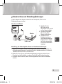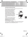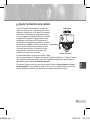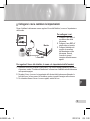
1
User’s Guide SCC-B5394/5395 ENG GER FRE SPA ITA TUR B68-00688D.indb Vari-focal Anti-Vandal Dome Camera 1 2007-07-06 ソタネト 2:38:3 B68-00688D.indb Safety Precautions CAUTION RISK OF ELECTRIC SHOCK DO NOT OPEN CAUTION: TO REDUCE THE RISK OF ELECTRIC SHOCK, DO NOT REMOVE REAR COVER. NO USER SERVICEABLE PARTS INSIDE. REFER TO QUALIFIED SERVICE PERSONNEL. This symbol indicates high voltage is present inside. It is dangerous to make any kind of contact with any inside part of this product. This symbol alerts you that important literature concerning operation and maintenance has been included with this product. To prevent damage which may result in fire or electric shock hazard, do not expose this appliance to rain or moisture. 3. 4. 5. 6. WARNING 1. 2. Be sure to use only the standard adapter that is specified in the specification sheet. Using any other adapter could cause fire, electrical shock, or damage to the product Incorrectly connecting the power supply or replacing battery may cause explosion, fire, electric shock, or damage to the product. 7. 8. Do not connect multiple cameras to a single adapter. Exceeding the capacity may cause abnormal heat generation or fire. Securely plug the power cord into the power receptacle. Insecure connection may cause fire. When installing the camera, fasten it securely and firmly. A falling camera may cause personal injury. Do not place conductive objects (e.g. screwdrivers, coins, metal things, etc.) or containers filled with water on top of the camera. Doing so may cause personal injury due to fire, electric shock, or falling objects. Do not install the unit in humid, dusty, or sooty locations. Doing so may cause fire or electric shock. If any unusual smells or smoke come from the unit, stop using the product. In such case, immediately disconnect the power source and contact the service center. Continued use in such a condition may cause fire or electric shock. 2 2 2007-07-06 ソタネト 2:38:3 If this product fails to operate normally, contact the nearest service center. Never disassemble or modify this product in any way. (SAMSUNG is not liable for problems caused by unauthorized modifications or attempted repair.) 10. When cleaning, do not spray water directly onto parts of the product. Doing so may cause fire or electric shock. CAUTION 1. 2. 3. 4. 5. 6. 7. Do not drop objects on the product or apply strong shock to it. Keep away from a location subject to excessive vibration or magnetic interference. If you want to relocate the already installed product, be sure to turn off the power and then move or reinstall it. Remove the power plug from the outlet when then there is a lightning. Neglecting to do so may cause fire or damage to the product. Keep out of direct sunlight and heat radiation sources. It may cause fire. Install it in a place with good ventilation. Avoid aiming the camera directly towards extremely bright objects such as sun, as this may damage the CCD image sensor. Apparatus shall not be exposed to dripping or splashing and no objects filled with liquids, such as vases, shall be placed on the apparatus. 8. The Mains plug is used as a disconnect device and shall stay readily operable at any time. FCC Statement This device complies with part 15 of the FCC Rules. Operation is subject to the following two conditions: 1) This device may not cause harmful interference, and 2) This device must accept any interference received including interference that may cause undesired operation. ENG B68-00688D.indb 9. Note This equipment has been tested and found to comply with the limits for a Class A digital device, pursuant to part 15 of FCC Rules. These limits are designed to provide reasonable protection against harmful interference when the equipment is operated in a commercial environment. This equipment generates, uses, and can radiate radio frequency energy and, if not installed and used in accordance with the instruction manual, may cause harmful interference to radio communications. Operation of this equipment in a residential area is likely to cause harmful interference in which case the user will be required to correct the interference at his own expense. 3 3 2007-07-06 ソタネト 2:38:3 B68-00688D.indb Important Safety Instructions 1. 2. 3. 4. 5. 6. 7. Read these instructions. Keep these instructions. Heed all warnings. Follow all instructions. Do not use this apparatus near water. Clean only with dry cloth. Do not block any ventilation openings. Install in accordance with the manufacturer’s instructions. 8. Do not install near any heat sources such as radiators, heat registers, or other apparatus (including amplifiers) that produce heat. 9. Do not defeat the safety purpose of the polarized or grounding-type plug. A polarized plug has two blades with one wider than the other. A grounding type plug has two blades and a third grounding prong. The wide blade or the third prong is provided for your safety. If the provided plug does not fit into your outlet, consult an electrician for replacement of the obsolete outlet. 10. Protect the power cord from being walked on or pinched particularly at plugs, convenience receptacles, and the point where they exit from the apparatus. 11. Only use attachments/accessories specified by the manufacturer. 12. Use only with cart, stand, tripod, bracket, or table specified by the manufacturer, or sold with the apparatus. 13. Unplug this apparatus. When a cart is used, use caution when moving the cart/apparatus combination to avoid injury from tip-over. 14. Refer all servicing to qualified service personnel. Servicing is required when the apparatus has been damaged in any way, such as power-supply cord or plug is damaged, liquid has been spilled or objects have fallen into the apparatus, the apparatus has been exposed to rain or moisture, does not operate normally, or been dropped. 4 4 2007-07-06 ソタネト 2:38:3 Overview.............................................................................................. 6 About this guide ............................................................................6 Product overview...........................................................................6 Main features .................................................................................6 Components...................................................................................7 Checking components in the package .......................................7 Components of your camera ......................................................8 ENG B68-00688D.indb Contents Installation.......................................................................................... 9 Setting switches ............................................................................9 Setting function switches............................................................9 Connecting cables and changing the settings ......................... 11 Installing camera .........................................................................12 Before installation.....................................................................12 About the installation holes ......................................................12 Installing on a pipe ...................................................................13 Installing the camera on the ceiling ..........................................15 Disassembling/assembling the Main body from the Case .......16 Adjusting the camera direction ..................................................17 Appendix A: Specifications for NTSC Standard ................. 19 Appendix B: Specifications for PAL Standard ............................... 20 5 5 2007-07-06 ソタネト 2:38:3 B68-00688D.indb Overview ❚ About this guide ❚ Main features This user guide includes basic instructions for the product. It is recommended that all users read this guide before use. Power: DC 12V/AC 24V Special functions Line lock (LL) control Auto white balancing Horizontal/vertical image reversing Flickerless control Low shutter speed control Backlight compensation control Automatic switching between color and black & white modes Equipped with vari-focal lens Auto Iris function Digital noise reduction (DNR) Dynamic CCD defect compensation This guide is divided as follows: Chapter 1, “Overview,” introduces the user guide and product related information. (This chapter) Chapter 2, “Installation,” explains how to set and install the product. Appendix, “Specifications,” provides the specifications of the product. ❚ Product overview This anti-vandal dome camera provides the superb monitoring features in bank and business areas and it is a water-proof and vibration-proof camera, which can strongly endure an external impact. This vari-focal camera provides the digital noise reduction (DNR) and real-time CCD defect correction features for implementing a clear image. 6 6 2007-07-06 ソタネト 2:38:3 Checking components in the package Please check your camera and accessories are included in the package. Those components are as shown below: Camera Image Test Monitor Cable ENG B68-00688D_Eng.indd ❚ Components User’s Guide Part name Standard Quantity Usage Plastic anchor HUD 5 4 (EA) Attach each piece to screw connection holes for strengthening connection ASSY screw machine BH M5 X L6. (White+o-ring) 8 Used for filling in the holes when installing pipe and wall mount ASSY screw tapping TH M4xL30 (Black+ o-ring) 4 Used when installing your camera on the ceiling or wall L-Wrench TROX T-20 1 Used for assembling/ disassembling the Dome cover Template Gasket-pipe hole T2.5 W56 1 Used for guiding the installation 1 Used to make a wiring hole when installing the camera on the ceiling or wall Note The test monitor cable is used to test the camera by connecting to a portable display. If you really want to connect the camera to a monitoring display, use the BNC cable. 7 7 2007-08-13 ソタタ・10:50:2 B68-00688D.indb Components of your camera Your camera has the following components: 3 1 2 5 4 7 6 6 7 8 Lens @ 9 0 ! # 1. Dome cover: Covers the inner cover, lens, and main body to protect them. 2. Cover screw: Use it to assemble or disassemble both dome cover and case. 3. Inner cover: Covers the main body to protect it. 4. Wing locker: Push a long thin screwdriver into its narrow spot and press it outward when you want to remove the inner cover. 5. Main body: Includes a lens, a switch board, a PCB board, screws, and such. 6. Screws for assembly and disassembly: Using these 2 screws, the Main body is closely connected to the Case. 7. Hooker: By pulling the left/right levers in the arrow direction, the Main body can be detached from the Case. 8. Case: Used as a ceiling or wall fixture. It is fixed using four screws provided in the package. 9. Zoom lever: Using this lever, the lens zoom can be adjusted and fixed. 10. Focus lever: Using this lever, the lens focus can be adjusted and fixed. 11. Tilt fixing screw: Using this screw, the slope of the lens can be adjusted and fixed. 12. Switch board: Includes two kinds of control switches such as function switches and phase-control switches. The board has eight function switches in the middle and two phase-control buttons on each side of the function switch area. 13. Cable: Connect the Video connector to BNC cable and Power connector to power adapter. Video connector Power connector 8 8 2007-07-06 ソタネト 2:38:3 ❚ Setting switches Setting function switches To set the available functions on your camera, adjust eight switches as shown below: 3 H-REV 1. Switch 1 (LL): When this switch is set to OFF, the camera operates in the internal synchronization mode, while when it is 8 set to ON, the camera operates in the 7 line lock mode. 6 5 In the internal synchronization mode, the 4 camera always uses an inside crystal 3 oscillator for synchronization. However 2 if multiple cameras are connected to a 1 sequential switcher, picture rolling or flickering may occur when switching from one camera to another. In this case, you INC can set this switch to ON to solve this problem. The line lock mode allows the camera to use the phase of the AC power as Brief description the synchronization reference. In this Line lock ON/OFF mode, you can use the phase control buttons(INC/DEC). Sens-up or Low speed shutter ON/OFF Horizontal reverse ON/OFF Note 4 V-REV Vertical reverse ON/OFF 5 BLC Backlight compensation ON/OFF 6 FL Flickerless ON/OFF 7 D/N Automatic switching between color and black & white ON/OFF 8 AWB Automatic white balance ON/OFF DEC No Name 1 LL 2 LSS ENG B68-00688D.indb Installation When you are using the DC 12V power, set this switch to OFF. The line lock feature will not normally operate even when the switch is set to ON. 9 9 2007-07-06 ソタネト 2:38:4 B68-00688D.indb 2. 3. 4. 5. Set the LL switch to ON while the AC power is connected. If any picture roll happens, you have to adjust the phase using the phase-control buttons. Press the INC or DEC button to increase or decrease the phase by one degree. Switch 2 (LSS): This sens-up mode accumulates the image fields in memory to reduce noise but increase the brightness and contrast rate. When this switch is set to ON, the camera automatically switches to a maximum of 128 times of image acquisition speed to implement a clear picture for darker image. Switch 3 (H-REV): When this switch is set to ON, the camera image is reversed horizontally. If you want to monitor your site using a mirror, you can use this feature to see the right image. Switch 4 (V-REV): When this switch is set to ON, the camera image is reversed vertically. If your camera reluctantly displays the vertically reversed image, you can use this feature to see the right image. Switch 5 (BLC): When this switch is set to ON, you can view a clear image even though the camera faces any excessive light such as sunlight and fluorescent light. When it is set to OFF, the subject with excessive light is not clearly shown. 6. Switch 6 (FL): When this switch is set to ON, the shutter speed is fixed to 1/100 sec (for NTSC) or 1/120 sec (for PAL) to prevent screen from flickering by the disaccordance between vertical synchronous frequency (50Hz for NTSC, 60Hz for PAL) and on-andoff frequency of a light. 7. Switch 7 (D/N): When this switch is set to ON, the camera automatically switches between color and B&W according to the brightness of the vicinity. 8. Switch 8 (AWB): This switch adjusts white balancing. When this switch is set to ON, this camera operates in ATW mode, and in case of OFF, this camera operates in AWC mode. ATW (Auto Tracking White Balance): The color temperature is automatically adjusted according to the environmental change. (Approx. 2000°K to 11,000°K) AWC (Auto White Balance Control): It stores the color temperature just when the switch is changed to OFF. Accordingly color temperatures are adjusted by the stored value. Caution -. The IRIS setting range for the camera is approximately 80 to 120 IRE. It means the camera does not provide the IRIS full open/close feature but the restricted variation range. -. Use the camera after setting to the proper level (80 IRE or above) because the IRIS hunting may occur when the level is 75 IRE or below. 10 10 2007-07-06 ソタネト 2:38:4 Before installing your camera, you have to adjust the lens focus, zoom, and switch settings. To connect cables Monitor BNC Cable 1. Connect the BNC cable to the Video connector attached on your camera. 2. Connect the BNC cable to the Video Input on a monitor. 3. Connect the power adapter to the Power connector attached on your camera. When the monitor is turned on, the camera image appears. ENG B68-00688D.indb ❚ Connecting cables and changing the settings To adjust the lens focus, zoom, and function settings 1. Remove the Cover dome and Inner cover. For more details about the removing procedures, see “Installation procedure,” in the Installing camera section on the next page. 2. Adjust the focus, zoom, and function settings of your camera using the Focus lever, Zoom lever, and Switch board while you are viewing the image on the screen. 3. If you want to fix the adjusted focus and zoom, screw up the levers. 11 11 2007-07-06 ソタネト 2:38:4 B68-00688D.indb ❚ Installing camera Before installation Before installing your camera, you have to read the following cautions: You have to check whether the location (ceiling or wall) can bear five times the weight of your camera. Don’t let the cable to be caught in improper place or the electric line cover to be damaged. Otherwise it may cause a breakdown or fire. You can use wall mount adaptor (SADT-102WM), and pole mount adaptor (SADT-100PM) for installing the camera on the wall or pipeline. When installing your camera, don’t allow any person to approach the installation site. If you have any valuable things under the place, move them away. About the installation holes Bottom of camera A B C A: Use these holes when directly installing your camera on the ceiling or wall. While those are not used, fill in the holes using the screw machine (M5 X L6.) for waterproofing. B: Use four holes when directly installing your camera on the junction box You can use the 4 1/8 diameter round type junction box for assembly. (The junction box, gasket, and cover are separately purchased items.) C: Use these holes when installing the wall mount adapter (SADT-102WM) While those are not used, fill in the holes using the screw machine (M5 X L6.) for waterproofing. The holes that are not used should be tightly sealed up using the screws provided for waterproofing. When the screws don’t have rubber rings inside or are not closely attached, note that it can cause waterproofing problem. For attaching screws, see page 16 “Disassembling/assembling the Main body from the Case.” 12 12 2007-07-06 ソタネト 2:38:4 To install your camera bottom on a pipe 1. After connecting the power and video cables, throw them inside the pipeline and screw the male thread pipe into the female pipe thread in your camera tightly to fix the Main body. (In this case, be sure to tape with Teflon tape before assembly for waterproofing. Be careful for the wiring cable not to be stuck in the connection area.) 3. Attach the Dome cover. (Screw the connection bolts tightly using the L-Wrench for waterproofing.) To change the SAMSUNG logo position, move the location of the connection rubber band as show below and rotate for assembly. (The rotation limit is 180 degree.) ENG B68-00688D.indb Installing on a pipe Before installation, you have to be familiar with the above cautions and fill in the holes that are not used for installation. 2. Adjust the angle of the camera in search of a better view. 1) Separate the Dome cover using the L-Wrench provided. (To make loose the screws, rotate counterclockwise.) 2) Adjust the lens direction. For more information, see page 17 “Adjusting the camera direction.” 13 13 2007-07-06 ソタネト 2:38:4 B68-00688E.indb To install the camera side on a pipe 1. Pull the power and video cables through the pipe connection hole on the camera side 1) Remove the side cover from the Case using a coin or minus (-) driver. (Rotate counterclockwise.) 2) Push the power and video cables stretched outside of the bottom hole into the Case. And pull them out from the side cover of the Case. 2. Attach the removed side cover to the bottom hole and rotate it clockwise using a coin or minus (-) driver. (Be sure to insert the O-ring (P22 T2.4) into the hole before assembly. The ring is necessary for waterproofing.) 3. After pulling the power and video cables through the connection pipe, screw the male thread pipe into the female pipe thread in your camera tightly to fix the Main body. (In this case, be sure to tape with Teflon tape before assembly for waterproofing. Be careful for the wiring cable not to be stuck in the connection area.) 4. Adjust the lens direction. For more information, see page 17, “Adjusting the camera direction.” 5. Attach the Dome cover. For more information, see step 3 in “To install your camera bottom on a pipe” on page 13. 14 14 2007-07-06 ソタネト 2:46:5 To install your camera bottom on a pipe 1. Attach the provided template to the place to be installed and penetrate a hole (5mm diameter, minimum depth 35mm) for fixing your camera to insert the provided plastic anchor (HUD 5) to the full. 2. After connecting both power and video cables, put them in order not to have damage during installation. 3. Remove the Dome cover. For more information, see step 2 in “To install your camera bottom on a pipe” on page 13. 4. Install your camera. After aligning the hole where the plastic anchor is inserted with the camera installation hole, make tight four ASSY screw-tappings where O-rings are inserted. (If no O-rings are inserted, water leak may happen.) 5. Adjust the camera lens direction. For more information, see page 17, “Adjusting the camera direction.” 6. Attach the Dome cover. For more information, see step 3 in “To install your camera bottom on a pipe” on page 13. In case of wiring after penetrating a hole on the installation site 1 Penetrate a wiring hole toward the pipe. (Recommended hole size: within 30mm diameter) 2 Attach the gasket on the bottom of the product as shown below. You have to correctly align the hole with the pipe hole. If the hole deviates from the gasket, water leak may happen. ENG B68-00688D.indb Installing the camera on the ceiling Before installation, you have to be familiar with the above cautions and fill in the holes that are not used for installation. Gasket 15 15 2007-07-06 ソタネト 2:38:4 B68-00688D.indb Disassembling/assembling the Main body from the Case The holes that are not used should be tightly sealed up using the screws provided for waterproofing. To detach the Main body from the Case, follow the instructions below: 1. 1. Remove the Dome cover first. 2. Detach the Main body of the camera from the Case. 1) Make loose two screws by rotating counterclockwise. 2) Detach the Main body of the camera after unlocking by pulling the left and right levers in the arrow direction. 3. Assemble the Main body of the camera with the Case. (Align three alignment grooves of the Main body with the bumps of the Case and assemble them.) 1) 4. Attach the Dome cover using the L-Wrench. For more information, see step 3 in “To install your camera bottom on a pipe” on page 13. 2) 16 16 2007-07-06 ソタネト 2:38:4 Panning When the camera is fixed on the ceiling, you can adjust the camera viewing angle. You can rotate your camera leftward or rightward (Panning), and can change the slope of your camera upward or downward (Tilting). In case of panning, the rotation limit of your camera is set to 355 degree (100 degree clockwise and 255 degree counterclockwise). The rotation is stopped by the Stopper inside of the camera. For panning control, first unfasten two screws located on the bottom and rotate in the direction you want, and then fasten them to fix the camera. Tilting ENG B68-00688D.indb ❚ Adjusting the camera direction In case of tilting, you can change the slope of your Lens rotation camera from zero to 90 degree. However if the slope angle is under 17 degree, you can encounter a partial image hide problem. To fix the location after adjusting the tilting angle, use the Tilt fixing screws. To adjust the focus and zoom of your camera, use the Zoom lever and Focus lever. When you install the camera on the inclined ceiling or wall, you can rotate the camera lens to see a correct direction image. 17 17 2007-07-06 ソタネト 2:38:4 B68-00688D.indb SCC-B539X 18 18 2007-07-06 ソタネト 2:38:4 Item Product type Power input Broadcast type Power consumption Image device Pixels Scanning mode Scanning line frequency Synchronization mode Horizontal resolution S/N Ratio Min. object illumination Signal output Lens PAN function TILT function Controls Operation temperature Operation humidity Size Weight Details CCTV color dome camera AC 24V ± 10% (60Hz ± 0.3 Hz), DC 12V +10%/-5% NTSC Standard System (525 Lines, 60 Fields) Approx. 1.7W 1/3 inch IT Type Super-HAD CCD Total: 811(H) x 508(V), 410,000 pixels Effective: 768(H) x 494(V), 380,000 pixels 525 Lines, 2:1 Interlace Horizontal: 15.734Hz(INT)/15.750Hz(LL) Vertical: 59.94Hz(INT)/60Hz(LL) INT/Line Lock (Adjusting the phase using INC/DEC button) 540 TV Lines Approx. 50dB SCC-B5395 (Color/BW) SCC-B5394 (Color/BW) 50IRE 0.4/0.04Lux 0.4/0.4Lux 30IRE 0.24/0.024Lux 0.24/0.24Lux Sens-up Off 15IRE 0.12/0.012Lux 0.12/0.12Lux F1.2 50IRE 0.0031/0.00031Lux 0.0031/0.0031Lux Sens-up x128 30IRE 0.0019/0.00019Lux 0.0019/0.0019Lux 15IRE 0.0009/0.00009Lux 0.0009/0.0009Lux COMPOSITE Video(1.0 Vp-p, 75ohm, BNC), Test Monitor OUT(1.0 Vp-p, 75ohm, Harness cable) Auto Iris (DC) Focal length: 2.9 ~ 10.0mm Aperture ratio: 1.2 Range: 0 to 355° (100 degree clockwise and 255 degree counterclockwise) Range: 0 to 90° Line Lock (LL) Sens-Up; Low Speed Shutter(LSS) Horizontal Reverse (H-REV) Vertical Reverse (V-REV) Backlight compensation (BLC) Flickerless (FL) Switching between color and B&W modes (D/N) Auto white balancing (AWB) Digital noise reduction (DNR) Dynamic CCD defect compensation -10°C to +50°C Up to 90% 150(Ø) x 121(H)mm SCC-B539X: 1.1kg ENG B68-00688D_Eng.indd Appendix A: Specifications for NTSC Standard 19 19 2007-08-30 ソタネト 7:16:3 Appendix B: Specifications for PAL Standard Item Product type Power input Broadcast type Power consumption Image device Pixels Scanning mode Scanning line frequency Synchronization mode Horizontal resolution S/N Ratio Min. object illumination Signal output Lens PAN function TILT function Controls Operation temperature Operation humidity Size Weight Details CCTV color dome camera AC 24V ± 10% (50Hz ± 0.3 Hz), DC 12V +10%/-5% PAL Standard System (625 Lines, 50 Fields) Approx. 1.7W 1/3 inch IT Type Super-HAD CCD Total: 795(H) x 596(V), 470,000 pixels Effective: 752(H) x 582(V), 440,000 pixels 625 Lines, 2:1 Interlace Horizontal: 15.625Hz(INT)/15.625Hz(LL) Vertical: 50Hz(INT)/50Hz(LL) INT/Line Lock (Adjusting the phase using INC/DEC button) 540 TV Lines Approx. 50dB SCC-B5395 (Color/BW) SCC-B5394 (Color/BW) 50IRE 0.4/0.04Lux 0.4/0.4Lux 30IRE 0.24/0.024Lux 0.24/0.24Lux Sens-up Off 15IRE 0.12/0.012Lux 0.12/0.12Lux F1.2 50IRE 0.0031/0.00031Lux 0.0031/0.0031Lux Sens-up x128 30IRE 0.0019/0.00019Lux 0.0019/0.0019Lux 15IRE 0.0009/0.00009Lux 0.0009/0.0009Lux COMPOSITE Video(1.0 Vp-p, 75ohm, BNC), Test Monitor OUT(1.0 Vp-p, 75ohm, Harness cable) Auto Iris (DC) Focal length: 2.9 ~ 10.0mm Aperture ratio: 1.2 Range: 0 to 355° (100 degree clockwise and 255 degree counterclockwise) Range: 0 to 90° Line Lock (LL) Sens-Up; Low Speed Shutter(LSS) Horizontal Reverse (H-REV) Vertical Reverse (V-REV) Backlight compensation (BLC) Flickerless (FL) Switching between color and B&W modes (D/N) Auto white balancing (AWB) Digital noise reduction (DNR) Dynamic CCD defect compensation -10°C to +50°C Up to 90% 150(Ø) x 121(H)mm SCC-B539X: 1.1kg 20 B68-00688D_Eng.indd 20 2007-08-30 ソタネト 7:16:3 B68-00688D.indb Correct Disposal of This Product (Waste Electrical & Electronic Equipment) (Applicable in the European Union and other European countries with separate collection systems) This marking shown on the product or its literature, indicates that it should not be disposed with other household wastes at the end of its working life. To prevent possible harm to the environment or human health from uncontrolled waste disposal, please separate this from other types of wastes and recycle it responsibly to promote the sustainable reuse of material resources. Household users should contact either the retailer where they purchased this product, or their local government office, for details of where and how they can take this item for environmentally safe recycling. Business users should contact their supplier and check the terms and conditions of the purchase contract. This product should not be mixed with other commercial wastes for disposal. 21 2007-07-06 ソタネト 2:38:5 B68-00688D.indb 22 2007-07-06 ソタネト 2:38:5 Benutzerh andbuch SCC-B5394/5395 GER B68-00688D.indb Vari-focal Anti-Vandal Dome Kamera 1 2007-07-06 ソタネト 2:38:5 B68-00688D.indb Sicherheitsvorsichtsmaßnahmen WARNUNG GEFAHR EINES ELEKTROSCHOCKSNICHT ÖFFNEN WARNUNG: NICHT DIE RÜCKSEITIGE ABDECKUNG ÖFFNEN, UM DIE GEFAHR EINES ELEKTROSCHOCKS ZU SENKEN. KEINE VOM BENUTZER ZU WARTENDE TEILE INNEN. WENDEN SIE SICH AN QUALIFIZIERTES KUNDENDIENSTPERSONAL. Dieses Symbol weist auf hohe Spannung im Innern des Geräts hin. Der Kontakt mit innenliegenden Teilen dieses Produktes ist gefährlich. Dieses Symbol macht Sie darauf aufmerksam, dass wichtige Dokumente bezüglich Betrieb und Wartung dem Produkt beiliegen. Setzen Sie dieses Gerät nicht Regen oder Feuchtigkeit aus, um Schäden zu vermeiden, die Brand oder Elektroschock zur Folge haben können. WARNUNG 1. 2. 2 2 Achten Sie darauf, nur den im Datenblatt angegebenen StandardAdapter zu verwenden. Die Verwendung eines anderen Adapters kann Brand, Elektroschock oder Schäden am Produkt verursachen. Falscher Anschluss des Netzkabels oder Austausch der Batterie kann Explosion, Brand, Elektroschock oder Schäden am Produkt zur Folge haben. 3. 4. 5. 6. 7. 8. Schließen Sie nicht mehrere Kameras an einen einzelnen Adapter an. Überschreiten der Kapazität kann abnormale Wärme oder Brand erzeugen. Schließen Sie das Netzkabel sicher an die Steckdose an. Ein ungesicherter Anschluss kann einen Brand verursachen. Wenn Sie die Kamera installieren, befestigen Sie sie sicher und fest. Eine herunterfallende Kamera kann Körperverletzungen verursachen. Stellen Sie keine leitenden Gegenstände (z.B. Schraubendreher, Münzen, Metallgegenstände, usw.) oder Behälter mit Wasser auf die Kamera. Dies kann sonst Körperverletzungen aufgrund von Brand, Elektroschock oder herunterfallenden Gegenständen verursachen. Installieren Sie das Gerät nicht an feuchten, staubigen oder rußigen Standorten. Dies führt sonst zu Brand oder Elektroschock. Verwenden Sie das Produkt nicht weiter, wenn eine ungewöhnliche Geruchs- oder Rauchentwicklung auftritt. Ziehen Sie in diesem Fall sofort den Netzstecker und wenden Sie sich an den Kundendienst. Wenn Sie das Gerät unter diesen Bedingungen weiterhin verwenden, kann Brand oder Elektroschock resultieren. 2007-07-06 ソタネト 2:38:5 Wenn dieses Produkt nicht einwandfrei funktioniert, wenden Sie sich an den nächstgelegenen Kundendienst. Zerlegen oder modifizieren Sie dieses Produkt nie in irgendeiner Weise. (SAMSUNG haftet nicht für Schäden, die durch unbefugte Änderungen oder Reparaturversuche verursacht werden.) 10. Spritzen Sie während der Reinigung kein Wasser direkt auf die Produktteile. Dies führt sonst zu Brand oder Elektroschock. 7. VORSICHT Dieses Gerät entspricht Abschnitt 15 der FCC-Normen. Der Betrieb unterliegt folgenden zwei Bedingungen: 1) Von diesem Gerät gehen keine schädlichen Interferenzen aus und 2) dieses Gerät muss empfangene Interferenzen einschließlich der Interferenzen akzeptieren, die einen ungewollten Betrieb verursachen können. 1. 2. 3. 4. 5. 6. Lassen Sie keine Gegenstände auf das Produkt fallen oder setzen Sie es keinen starken Stößen aus. Halten Sie sich fern von Standorten die übermäßiger Erschütterung oder magnetischer Beeinflussung ausgesetzt sind. Wenn Sie das bereits installierte Gerät versetzen möchten, achten Sie darauf, die Stromversorgung abzuschalten und es dann erst zu versetzen und erneut zu installieren. Ziehen Sie den Netzstecker bei Gewitter. Nichtbeachtung kann Brand oder Schäden am Gerät verursachen. Halten Sie das Gerät fern von direktem Sonnenlicht und anderen Wärmestrahlungsquellen. Dies kann sonst zu Brand führen. Installieren Sie das Gerät an einem Ort mit guter Belüftung. Zielen Sie mit der Kamera nicht direkt in Richtung extrem heller Gegenstände wie zum Beispiel die Sonne, da dies den CCD-Bildsensor beschädigen kann. 8. Das Gerät darf nicht mit Wasser oder anderen Flüssigkeiten in Berührung kommen. Außerdem dürfen keine mit Flüssigkeiten gefüllten Behälter, wie beispielsweise Vasen, darauf abgestellt werden. Der Netzstecker sollte jederzeit in Reichweite und zugänglich sein, da er aus der Steckdose entfernt werden muss, um das Gerät vollständig abzuschalten. FCC-Angaben GER B68-00688D.indb 9. Hinweis DiesesGerät ist getestet worden und die Einschränkungen für ein Digitalgerät der Kategorie A wurden als erfüllt betrachtet, gemäß Abschnitt 15 der FCC-Normen. Diese Einschränkungen wurden festgelegt, um für angemessenen Schutz gegen schädliche Störanfälligkeit zu sorgen, wenn das Gerät in einer gewerblichen Umgebung betrieben wird. Dieses Gerät erzeugt, verwendet und kann Hochfrequenzenergie ausstrahlen und, falls es nicht in Übereinstimmung mit dem Bedienungshandbuch installiert und verwendet wird, schädliche Störungen beim Funkverkehr verursachen. Der Betrieb dieses Geräts in einem Wohngebiet verursacht sehr wahrscheinlich schädliche Störungen, in diesem Fall muss der Benutzer die Störungen auf seine eigenen Kosten beseitigen. 3 3 2007-07-06 ソタネト 2:38:5 B68-00688D.indb Wichtige Sicherheitshinweise 1. 2. 3. 4. 5. 6. 7. 8. 9. Lesen Sie diese Anweisungen. Bewahren Sie sie auf. Beachten Sie alle Warnungen. Befolgen Sie alle Anweisungen. Verwenden Sie dieses Gerät nicht in der Nähe von Wasser. Reinigen Sie es nur mit einem trockenen Lappen. Blockieren Sie keine Belüftungsöffnungen. Installieren Sie es gemäß den Herstelleranweisungen. Installieren Sie das Gerät nicht in der Nähe von Wärmequellen wie beispielsweise von Radiatoren, Heizkörpern oder anderen Geräten (einschließlich Verstärkern), die Wärme erzeugen. Bitte achten Sie darauf, die Schutzvorrichtung des gepolten bzw. geerdeten Steckers nicht zu beschädigen. Ein gepolter Stecker verfügt über zwei Stifte, von denen einer breiter als der andere ist. Ein geerdeter Stecker hat zwei Stifte und einen Erdungsstift. Der breite Stift oder der dritte Stift ist für Ihre Sicherheit vorgesehen. Wenn der vorgesehene Stecker nicht in Ihre Steckdose passt, wenden Sie sich an einen Elektriker, um die veraltete Steckdose austauschen zu lassen. 10. Schützen Sie das Netzkabel so, dass nicht darauf getreten wird, und dass es insbesondere an den Steckern oder passenden Steckdosen bzw. der Stelle, an der das Kabel das Gerät verlässt, nicht abgeklemmt wird. 11. Verwenden Sie nur die vom Hersteller angegebenen Zusatzgeräte/ Zubehörteile. 12. Verwenden Sie diese nur mit dem vom Hersteller angegebenen Wagen, Ständer, Stativ, Auflage oder Tisch, oder die mit dem Gerät zusammen verkauft wurden. 13. Ziehen Sie den Netzstecker dieses Geräts. Geben Sie Acht bei der Verwendung eines Wagens, wenn Sie die Wagen-/Gerätekombination verschieben, um Verletzungen durch Herunterfallen zu vermeiden. 14. Überlassen Sie alle Wartungsarbeiten qualifiziertem Kundendienstpersonal. Wartungsarbeiten sind erforderlich, wenn das Gerät in irgendeiner Weise beschädigt wurde, wie zum Beispiel ein beschädigtes Netzkabel oder Stecker, verschüttete Flüssigkeiten oder Gegenstände, die in das Gerät gefallen sind, das Gerät Regen oder Feuchtigkeit ausgesetzt wurde, nicht normal funktioniert oder fallen gelassen wurde. 4 4 2007-07-06 ソタネト 2:38:5 Übersicht ............................................................................................. 6 Über diese Anleitung .....................................................................6 Produktübersicht ...........................................................................6 Hauptfunktionen ............................................................................6 Teile 7 Prüfen Sie die Teile in der Verpackung ......................................7 Einzelteile Ihrer Kamera .............................................................8 Installation.......................................................................................... 9 Einstellung der Schalter ...............................................................9 Einstellung der Funktionsschalter ..............................................9 Kabelanschluss und Einstellungsänderungen......................... 11 Installation der Kamera ...............................................................12 Vor der Installation ...................................................................12 Über die Installations-Bohrlöcher .............................................12 Installation an einem Rohr .......................................................13 Installation der Kamera an der Decke ......................................15 Demontage/Montage des Hauptgehäuses vom Gehäuse .......16 Einstellen der Kamerarichtung ..................................................17 GER B68-00688D.indb Inhaltsangabe Anhang A: Spezifikationen für NTSC-Standard ................... 19 Anhang B: Spezifikationen für PAL-Standard ........................ 20 5 5 2007-07-06 ソタネト 2:38:5 B68-00688D.indb Übersicht ❚ Über diese Anleitung ❚ Hauptfunktionen Diese Bedienungsanleitung enthält grundlegende Anweisungen für das Gerät. Es wird empfohlen, dass alle Benutzer diese Anleitung vor Gebrauch lesen. Energie: DC 12V/AC 24V Sonderfunktionen Line-Lock-Regelung (LL) Automatischer Weißabgleich Kapitel 1, “Übersicht”, führt in das Benutzerhandbuch und die produktbezogenen Informationen ein. (Dieses Kapitel) Kapitel 2, “Installation”, beschreibt wie das Gerät einzustellen und zu installieren ist. Anhang, “Spezifikationen”, beschreibt die Spezifikationen des Produktes. Horizontale/vertikale Spiegelung Flimmerfreie Regelung Low-Speed-Shutter-Regelung Gegenlicht-Kompensationsregelung ❚ Produktübersicht Automatisches Umschalten zwischen Farb und Schwarz-/Weißmodi Ausgestattet mit Varifocal Objektiv Auto-Iris-Funktion Digitale Rauschminderung (DNR) Dynamische CCD-Fehlerkompensation Diese Anleitungist wie folgt unterteilt: Diese Antivandal-Domekameraliefert ausgezeichnete Überwachungseigenschaften in Bank- und Geschäftsbereichen. Sie ist eine wasserdichte und erschütterungssichere Kamera, die Stöße von außen gut aushalten kann. Diese Varifocal Kamera liefert digitale Rauschunterdrückung (DNR) und Echtzeit CCD-Fehlerkorrektureigenschaften für die Umsetzung eines deutlichen Bildes. 6 6 2007-07-06 ソタネト 2:38:5 Prüfen Sie die Teile in der Verpackung Überprüfen Sie bitte, ob Ihre Kamera und die Zubehörteile sich in der Verpackung befinden. Diese Teile sind wie folgt dargestellt: Kamera Bild Test Monitorkabel Benutzerhandbuch Name des Teils Standard Menge Verwendungszweck Kunststoffdübel HUD 5 4 (EA) Befestigen Sie jedes Teil an den Schraubverbindungen, um den Anschluss zu verstärken ASSY Metallgewindeschraube BH M5 X L6. (Weiß+O-ring) 8 Wird verwendet zum Abdichten der Bohrlöcher, wenn Rohr- und Wandhalterung montiert werden ASSY Blechschraube TH M4xL30 (Schwarz+ O-ring) 4 Wird für die Decken- oder Wandinstallation der Kamera verwendet L-Schlüssel TROX T-20 1 Wird für die Montage/Demontage der Kuppelabdeckung verwendet Schablone Dichtung-Rohröffnung 1 T2,5 W56 1 GER B68-00688D_Ger.indd ❚ Teile Wird als Führung für die Installation verwendet Wird verwendet, um ein Bohrloch für die Verkabelung bei Decken- oder Wandinstallation der Kamera durchzuführen Hinweis Das Test-Monitorkabel dient dazu, die Kamera durch Anschluss an einen tragbaren Bildschirm zu testen. Falls Sie die Kamera wirklich an einen Überwachungsbildschirm anschließen möchten, verwenden Sie das BNC-Kabel. 7 7 2007-08-13 ソタタ・10:51:3 B68-00688D.indb Einzelteile Ihrer Kamera 2 Ihre Kamera verfügt über folgende Einzelteile: 3 1 5 4 7 6 6 7 8 Objektiv @ 9 0 ! # Videobuchse Netzbuchse 1. Kuppelabdeckung: Dient als Schutz für die Innenabdeckung, das Objektiv und das Hauptgehäuse. 2. Schraube der Abdeckung: Dient für die Montage oder Demontage von Kuppelabdeckung und Gehäuse. 3. Innenabdeckung: Dient als Schutz für das Hauptgehäuse. 4. Flügelverriegelung: Drücken Sie einen langen, dünnen Schraubendreher in die enge Stelle der Flügelverriegelung und drücken Sie sie nach außen, wenn Sie die Innenabdeckung abnehmen möchten. 5. Hauptgehäuse: Beinhaltet ein Objektiv, eine Schalttafel, eine Leiterplatte, Schrauben und dergleichen. 6. Schrauben für die Montage und Demontage: Mit diesen 2 Schrauben wird das Hauptgehäuse fest an das Gehäuse angeschlossen. 7. Haken: Durch Ziehen der linken/rechten Hebel in Pfeilrichtung kann das Hauptgehäuse vom Gehäuse abgenommen werden. 8. Gehäuse: Dient zur Decken- oder Wandbefestigung. Es wird mit den 4 Schrauben befestigt, die in der Verpackung enthalten sind. 9. Zoomhebel: Mit diesem Hebel kann das Zoomobjektiv ein- und festgestellt werden. 10. Fokushebel: Mit diesem Hebel kann das Fokusobjektiv ein- und festgestellt werden. 11. Kipp-Befestigungsschraube: Mithilfe dieser Schraube kann die Neigung des Objektivs ein- und festgestellt werden. 12. Schalttafel: Umfasst zwei verschiedene Arten von Betätigungsschaltern, wie zum Beispiel Funktionsschalter und Schalter für die Phasenregelung. Die Tafel verfügt über acht Funktionsschalter in der Mitte und zwei Phasenregelungstasten auf der Seite des Funktionss chalterbereichs. 13. Kabel: Schließen Sie die Videobuchse an das BNCKabel und die Netzbuchse an den Netzadapter an. 8 8 2007-07-06 ソタネト 2:38:5 ❚ Einstellung der Schalter Einstellung der Funktionsschalter Verstellen Sie die acht Schalter wie nachfolgend dargestellt, um die verfügbaren Funktionen an Ihrer Kamera einzustellen: DEC 8 7 6 5 4 3 2 1 INC Nr. Name Kurzbeschreibung 1 LL Line-Lock EIN/AUS 2 LSS Sens-up oder Low-Speed-Shutter EIN/AUS 3 H-REV Horizontale Spiegelung EIN/AUS 4 V-REV Vertikale Spiegelung EIN/AUS 5 BLC Gegenlicht-Kompensation EIN/AUS 6 FL Flimmerfrei EIN/AUS 7 D/N Automatische Umschaltung zwischen Farbe und Schwarz/Weiß EIN/AUS 8 AWB Automatischer Weißabgleich EIN/AUS 1. Schalter 1 (LL): Wenn dieser Schalter auf AUS gestellt wird, läuft die Kamera im internen Synchronisationsmodus, wenn er jedoch auf EIN gestellt wird, läuft sie im Line-Lock-Modus. Beim internen Synchronisationsmodus verwendet die Kamera stets einen InnenKristalloszillator für die Synchronisation. Wenn jedoch mehrere Kameras an einen Folgeschalter angeschlossen werden, kann beim Umschalten von einer Kamera zur anderen das Kippen des Bildes oder Flimmern auftreten. In diesem Fall, können Sie diesen Schalter auf EIN stellen, um dieses Problem zu lösen. Der Line-Lock-Modus lässt die Kamera die Wechselstromphase als Synchronisationsreferenz verwenden. In diesem Modus können Sie die Phasenreglertasten (INC/DEC) betätigen. GER B68-00688D.indb Installation Hinweis Stellen Sie diesen Schalter auf AUS, wenn Sie 12V Gleichstrom verwenden. Die Line-Lock-Funktion funktioniert nicht wie gewöhnlich, wenn der Schalter auf EIN gestellt wird. 9 9 2007-07-06 ソタネト 2:39:0 B68-00688D.indb Stellen Sie den LL-Schalter auf EIN, während der Wechselstrom angeschlossen wird. Wenn das Bild kippt, müssen Sie die Phase mithilfe der Phasenreglertasten einstellen. Drücken Sie die Taste INC oder DEC, um die Phase um ein Grad zu erhöhen oder zu senken. 2. Schalter 2 (LSS): Dieser Sens-up-Modus sammelt die Bildfelder im Speicher, um das Rauschen zu mindern und gleichzeitig die Helligkeit und das Kontrastverhältnis zu erhöhen. Wenn dieser Schalter auf EIN gestellt wird, schaltet die Kamera automatisch auf maximal das 128-fache der Bilderfassungsgeschwindigkeit, um ein deutliches Bild für eine dunklere Darstellung zu implementieren. 3. Schalter 3 (H-REV): Wird dieser Schalter auf EIN gestellt, wird das Kamerabild horizontal gespiegelt. Wenn Sie Ihren Standort mit einem Spiegel überwachen möchten, können Sie diese Funktion nutzen, um die richtige Darstellung zu sehen. 4. Schalter 4 (V-REV): Wird dieser Schalter auf EIN gestellt, wird das Kamerabild vertikal gespiegelt. Wenn Ihre Kamera das vertikal gespiegelte Bild zu langsam anzeigt, können Sie diese Funktion nutzen, um die richtige Darstellung zu sehen. 5. Schalter 5 (BLC): Wird dieser Schalter auf EIN gestellt, können Sie selbst dann ein deutliches Bild betrachten, wenn die Kamera mit übermäßigem Licht wie zum Beispiel Sonnenlicht und fluoreszierendem Licht konfrontiert wird. Wird dieser Schalter auf AUS gestellt, wird der Gegenstand bei übermäßigem Licht nicht deutlich angezeigt. 6. Schalter 6 (FL): Wird dieser Schalter auf EIN gestellt, wird die Shutter-Speed auf 1/100 Sek (bei NTSC) oder 1/120 Sek (bei PAL) fest eingestellt, um zu verhindern, dass die Anzeige aufgrund der fehlenden Übereinstimmung zwischen vertikaler synchroner Frequenz (50Hz bei NTSC, 60Hz bei PAL) und Ein-undAus-Frequenz einesLichtes flimmert. 7. Schalter 7 (D/N): Wird dieser Schalter auf EIN gestellt, schaltet die Kamera je nach Helligkeit der Umgebung automatisch zwischen Farbe und Schwarz/Weiß um. 8. Schalter 8 (AWB): Dieser Schalter stellt den Weißabgleich ein. Wird dieser Schalter auf EIN gestellt, läuft die Kamera im ATW-Modus, und wird er auf AUS gestellt, läuft die Kamera im AWC-Modus. ATW (Automatischer Weißabgleich): Die Farbtemperatur wird automatisch entsprechend den Umgebungsänderungen eingestellt. (Ungefähr 2000°K bis 11.000°K) AWC (Automatische Weißabgleichregelung): Speichert die Farbtemperatur in dem Moment, wenn der Schalter auf AUS gesetzt wird. Dementsprechend werden die Farbtemperaturen anhand des gespeicherten Wertes eingestellt. Achtung -. Der Einstellbereich der Irisblende für die Kamera beträgt circa 80 bis 120 IRE. Das bedeutet, dass die Kamera nicht über die Funktion Irisblende vollständig öffnen/schließen, sondern über die eingeschränkte Variationsbreite verfügt. -. Benutzen Sie die Kamera nachdem Sie auf die entsprechende Stufe (80 IRE oder darüber) eingestellt haben, da eine Schwankung der Irisblende bei einer Stufe von 75 IRE oder darunter auftreten kann. 10 10 2007-07-06 ソタネト 2:39:0 Vor der Installation Ihrer Kamera, müssen Sie das Fokusobjektiv, Zoom und die Schaltereinstellungen einstellen. Anschluss der Kabel: Monitor BNC-Kabel 1. Schließen Sie das BNC-Kabel an den Videoanschluss an, der sich an Ihrer Kamera befindet. 2. Schließen Sie das BNCKabel an den VideoEingang am Monitor an. 3. Schließen Sie den Netzadapter an den an Ihrer Kamera befindlichen Netzanschluss an. Sobald der Monitor eingeschaltet wird, wird das Kamerabild angezeigt. GER B68-00688D.indb ❚ Kabelanschluss und Einstellungsänderungen Einstellung des Fokusobjektiv, Zoom und Funktionseinstellungen 1. Nehmen Sie die Kuppel- und die Innenabdeckung ab. Weitere Einzelheiten darüber, wie die Abdeckung abzunehmen ist, entnehmen Sie dem “Installationsverfahren” im Abschnitt ‘Installation der Kamera’ auf der nächsten Seite. 2. Stellen Sie Fokus-, Zoom- und Funktionseinstellungen Ihrer Kamera mit dem Fokus-, Zoomhebel und der Schalttafel ein, während Sie das Bild am Bildschirm betrachten. 3. Schrauben Sie die Hebel fest, wenn Sie den eingestellten Fokus und Zoom feststellen möchten. 11 11 2007-07-06 ソタネト 2:39:0 B68-00688D.indb ❚ Installation der Kamera Vor der Installation Vor der Installation Ihrer Kamera müssen Sie folgende Vorsichtsmaßregeln lesen: Sie müssen prüfen, ob der Standort (Decke oder Wand) das fünffache Gewicht Ihrer Kamera tragen kann. Lassen Sie das Kabel sich nicht an einer ungeeigneten Position verhaken oder die Umhüllung der elektrischen Leitung beschädigen. Ansonsten kann ein Defekt oder Brand verursacht werden. Sie können einen Wandmontage-Adapter (SADT-102WM) und Mastmontage-Adapter (SADT-100PM) für die Installation der Kamera an der Wand oder Rohrleitung verwenden. Lassen Sie keine Personen am Installationsstandort zu, wenn Sie Ihre Kamera installieren. Sollten sich wertvolle Gegenstände unter dem Installationsplatz befinden, müssen Sie sie entfernen. Über die Installations-Bohrlöcher Unterseite der Kamera A B C A: Benutzen Sie diese Bohrlöcher, wenn Sie Ihre Kamera direkt an der Decke oder der Wand installieren. Wenn diese nicht gebraucht werden, dichten Sie die Bohrlöcher mit der Metallgewindeschraube (M5 X L6.) ab, so dass sie wasserdicht sind. B: Verwenden Sie die vier Bohrlöcher, wenn Sie Ihre Kamera direkt am Abzweigkasten installieren möchten Sie können den runde Abzweigkasten mit einem Durchmesser von 4 1/8 für die Montage verwenden. (Der Abzweigkasten, die Dichtung und die Abdeckung können separat erworben werden.) C: Verwenden Sie diese Bohrlöcher, wenn Sie den Wandmontage-Adapter (SADT-102WM) installieren Wenn diese nicht gebraucht werden, dichten Sie die Bohrlöcher mit der Metallgewindeschraube (M5 X L6.) ab, so dass sie wasserdicht sind. Die Bohrlöcher, die nicht gebraucht werden, sollten fest mit den für die Wasserdichtheit vorgesehenen Schrauben abgedichtet werden. Beachten Sie, dass Sie Probleme in Bezug auf Wasserdichtheit bekommen, wenn die Schrauben keine Gummiringe innen aufweisen oder nicht fest genug befestigt sind. Siehe Seite 16 “Demontage/Montage des Hauptgehäuses vom Gehäuse” für die Befestigung der Schrauben. 12 12 2007-07-06 ソタネト 2:39:0 Für die Installation Ihrer Kameraunterseite auf einem Rohr 1. Verlegen Sie nach Anschluss der Netzund Videokabel, diese nach innen in die Rohrleitung und schrauben Sie das Außengewinde des Rohres in dem Innengewinde Ihrer Kamera fest, um das Hauptgehäuse zu befestigen. (Vergewissern Sie sich hier, dass Sie wegen Wasserdichtheit vor der Montage mit einem Teflonband umwickeln. Passen Sie auf, dass das Verdrahtungskabel nicht im Anschlussbereich eingeklemmt wird.) 2) Stellen Sie die Objektivrichtung ein. Weitere Informationen entnehmen Sie der Seite 17 “Einstellen der Kamerarichtung.” 3. Befestigen Sie die Kuppelabdeckung. (Schrauben Sie die Verschraubung aus Gründen der Imprägnierung mithilfe des L-Schlüssels fest.) Verschieben Sie die Position des Anschlussgummibandes wie unten dargestellt und drehen Sie es für die Montage, um die SAMSUNG LogoPosition zu ändern. (Das Rotationslimit ist 180 Grad.) GER B68-00688D.indb Installation an einem Rohr Sie müssen sich vor der Installation mit den oben aufgeführten Vorsichtsmaßnahmen vertraut machen und die Bohrlöcher abdichten, die für die Installation nicht gebraucht werden. 2. Justieren Sie den Kamerawinkel bei der Suche auf bessere Sicht. 1) Trennen Sie die Kuppelabdeckung mit dem vorgesehenen L-Schlüssel. (Drehen Sie entgegen dem Uhrzeigersinn, um die Schrauben zu lösen.) 13 13 2007-07-06 ソタネト 2:39:0 B68-00688D.indb Installation der Kameraseite auf einem Rohr 1. Ziehen Sie die Netz- und Videokabel durch das Anschlussbohrloch des Rohrs an der Seite der Kamera 1) Nehmen Sie die seitliche Abdeckung vom Gehäuse mit einer Münze oder einem Schlitzschraubendreher (-). (Drehen Sie entgegen dem Uhrzeigersinn.) 2) Drücken Sie die Netz- und Videokabel, die aus dem unteren Bohrloch herausragen in das Gehäuse. Und ziehen Sie sie von der seitlichen Abdeckung des Gehäuses heraus. 2. Befestigen Sie die abgenommene seitliche Abdeckung an dem unteren Bohrloch und drehen Sie sie mithilfe einer Münze oder eines Schlitzschraubendrehers (-) im Uhrzeigersinn. (Achten Sie darauf, den O-ring (P22 T2.4) vor der Montage in das Bohrloch einzuführen. Der Ring ist für die Wasserdichtheit erforderlich.) 3. Schrauben Sie nach Anschluss der Netzund Videokabel das Außengewinde des Rohres fest in das Innengewinde Ihrer Kamera, um das Hauptgehäusefest anzubringen. (Vergewissern Sie sich in diesem Fall, dass Sie wegen Wasserdichtheit vor der Montage mit einem Teflonband umwickeln. Passen Sie auf, dass das Verdrahtungskabel nicht im Anschlussbereich eingeklemmt wird.) 4. Stellen Sie die Objektivrichtung ein. Weitere Informationen entnehmen Sie der Seite 17 “Einstellen der Kamerarichtung.” 5. Befestigen Sie die Kuppelabdeckung. Weitere Informationen siehe Schritt 3 unter “Für die Installation Ihrer Kameraunterseite auf einem Rohr” auf Seite 13. 14 14 2007-07-06 ソタネト 2:39:0 Für die Installation Ihrer Kameraunterseite auf einem Rohr 1. Befestigen Sie die enthaltene Schablone am Installationsort und stechen Sie ein Bohrloch durch (Durchmesser 5 mm, Mindesttiefe 35 mm) für die Befestigung Ihrer Kamera, um die vorgesehenen Kunststoffdübel (HUD 5) ganz einzuführen. 2. Legen Sie sowohl Netz- und Videokabel nach dem Anschluss geordnet hin, um Beschädigungen bei der Installation zu vermeiden. 3. Nehmen Sie die Kuppelabdeckung ab. Weitere Informationen siehe Schritt 2 unter “Für die Installation Ihrer Kameraunterseite auf einem Rohr” auf Seite 13. 4. Installieren Sie Ihre Kamera. Befestigen Sie die Kamera fest mit den vier ASSY Blechschrauben, wo die O-Ringe eingesetzt sind, nachdem Sie das Bohrloch mit den eingesetzten Kunststoffdübeln auf das Installationsbohrloch der Kamera ausgerichtet haben. (Wenn keine O-Ringe eingesetzt werden, kann ein Wasserleck auftreten.) 5. Stellen Sie die Objektivrichtung der Kamera ein. Weitere Informationen entnehmen Sie der Seite 17 “Einstellen der Kamerarichtung.” Verdrahtung 6.Bei Befestigen Sie dienach Kuppelabdeckung. Durchbruch eines Bohrlochs am Weitere Informationen siehe Schritt Installationsort 3 unter “Für die Installation Ihrer auf einem Rohr” auf 1 Kameraunterseite Brechen Sie ein Verkabelungsbohrloch Seite 13. in Richtung Rohr durch. (Empfohlene Bohrlochgröße: innerhalb eines Durchmessers von 30 mm) 2 Befestigen Sie die Dichtung an der Unterseite des Gerätes, wie unten dargestellt. Sie müssen das Bohrloch korrekt auf das Bohrloch des Rohres ausrichten. Wenn das Bohrloch von der Dichtung abweicht, kann ein Wasserleck auftreten. GER B68-00688D.indb Installation der Kamera an der Decke Sie müssen sich vor der Installation mit den oben aufgeführten Vorsichtsmaßnahmen vertraut machen und die Bohrlöcher abdichten, die für die Installation nicht gebraucht werden. Dichtung 15 15 2007-07-06 ソタネト 2:39:0 B68-00688D.indb Demontage/Montage des Hauptgehäuses vom Gehäuse Die Bohrlöcher, die nicht gebraucht werden, sollten fest mit den Schrauben abgedichtet werden, so dass sie wasserdicht sind. Befolgen Sie nachfolgende Anweisungen, um das Hauptgehäuse vom Gehäuse abzunehmen: 1. 1. Nehmen Sie zuerst die Kuppelabdeckung ab. 2. Nehmen Sie dann das Hauptgehäuse der Kamera vom Gehäuse ab. 1) Lösen Sie beide Schrauben, indem Sie sie entgegen dem Uhrzeigersinn drehen. 2) Nehmen Sie das Hauptgehäuse der Kamera nach dem Entriegeln ab, indem Sie die linken und rechten Hebel in Pfeilrichtung ziehen. 3. Montieren Sie das Hauptgehäuse der Kamera am Gehäuse. (Richten Sie die drei Ausrichtungskerben des Hauptgehäuses auf die Erhebungen des Gehäuses aus und montieren Sie sie.) 1) 2) 4. Befestigen Sie die Kuppelabdeckung mit dem L-Schlüssel. Weitere Informationen siehe Schritt 3 “Für die Installation Ihrer Kameraunterseite auf einem Rohr” auf Seite 13. 16 16 2007-07-06 ソタネト 2:39:0 Wenn die Kamera an der Decke befestigt ist, können Sie den Kamerabetrachtungswinkel einstellen. Sie können Ihre Kamera nach links oder rechts drehen (Schwenken) und Sie können Ihre Kamera nach oben oder unten neigen (Kippen). Schwenken Beim Schwenken ist das Rotationslimit Ihrer Kamera auf 355 Grad (100 Grad im Uhrzeigersinn und 255 Grad entgegen dem Uhrzeigersinn) eingestellt. Die Rotation wird durch den Stopper innerhalb der Kamera gestoppt. Lösen Sie für die Schwenkregelung zuerst die beiden Schrauben, die sich an der Unterseite befinden. Drehen Sie dann in die von Ihnen gewünschte Richtung und ziehen Sie die Schrauben wieder an, um die Kamera zu befestigen. Beim Kippen können Sie die Neigung Ihrer Kamera von null bis zu 90 Grad ändern. Wenn jedoch der Neigungswinkel unter 17 Grad ist, kann das Bild teilweise ausgeblendet sein. Verwenden Sie die Kipp-Befestigungsschrauben, um die Position nach Einstellung des Kippwinkels zu befestigen. Kippen GER B68-00688D.indb ❚ Einstellen der Kamerarichtung Objektivdrehung Verwenden Sie den Zoom- und Fokushebel, um Fokus und Zoom Ihrer Kamera einzustellen. Wenn Sie die Kamera an einer schrägen Decke oder Wand installieren, können Sie das Kameraobjektiv drehen, um eine korrekte Bildrichtung zu sehen. 17 17 2007-07-06 ソタネト 2:39:0 B68-00688D.indb SCC-B539X 18 18 2007-07-06 ソタネト 2:39:0 Objekt Produkttyp Leistungsaufnahme Übertragungsart Leistungsaufnahme Bildwandler Pixel Abtastmodus Abtastrate Synchronisationsmodus Horizontale Auflösung Signal-Rauschabstand Min. Lichtstärke des Objekts Ausgangssignal Objektiv PAN Funktion TILT (Kipp)-Funktion Regelungen Betriebstemperatur Betriebsfeuchtigkeit Größe Gewicht Beschreibung CCTV Farb-Domekamera 24V Wechselstrom ± 10% (60Hz ± 0,3 Hz), 12V Gleichstrom +10%/-5% NTSC-Standard System (525 Zeilen, 60 Felder) Ungefähr 1,7W 1/3 Zoll IT Typ Super-HAD CCD Gesamt: 811(H) x 508(V), 410.000 Pixel Effektiv: 768(H) x 494(V), 380.000 Pixel 525 TV-Linien, 2:1 Interlace Horizontal: 15,734Hz(INT)/15,750Hz(LL) Vertikal: 59,94Hz(INT)/60Hz(LL) INT/Line Lock (Einstellen der Phase mit der Taste INC/DEC) 540 TV-Linien ca. 50 dB SCC-B5395 (Color/BW) SCC-B5394 (Color/BW) 50IRE 0,4/0,04Lux 0,4/0,4Lux 30IRE 0,24/0,024Lux 0,24/0,24Lux Sens-up Off 15IRE 0,12/0,012Lux 0,12/0,12Lux F1,2 50IRE 0,0031/0,00031Lux 0,0031/0,0031Lux Sens-up x128 30IRE 0,0019/0,00019Lux 0,0019/0,0019Lux 15IRE 0,0009/0,00009Lux 0,0009/0,0009Lux COMPOSITE Video(1,0 Vp-p, 75ohm, BNC), Test Monitor OUT(1,0 Vp-p, 75ohm, Kabel- baum) Autoiris (DC) Brennweite: 2,9 ~ 10,0 mm Öffnungsverhältnis: 1,2 Reichweite: 0 bis 355° (100 Grad im Uhrzeigersinn und 255 Grad entgegen dem Uhrzeigersinn) Reichweite: 0 bis 90° Line-Lock (LL) Sens-up; Low-Speed-Shutter(LSS) Horizontale Spiegelung (H-REV) Vertikale Spiegelung (V-REV) Gegenlicht-Kompensation (BLC) Flackerfrei (FL) Umschalten zwischen Farb- und Schwarz-/Weißmodi (D/N) Automatischer Weißabgleich (AWB) Digitale Rauschminderung (DNR) Dynamische CCD Fehlerkompensation -10°C bis +50°C bis zu 90% 150(Ø) x 121(H) mm SCC-B539X: 1,1kg GER B68-00688D_Ger.indd Anhang A: Spezifikationen für NTSC-Standard 19 19 2007-08-30 ソタネト 7:21:3 Anhang B: Spezifikationen für PAL-Standard Objekt Produkttyp Leistungsaufnahme Übertragungsart Leistungsaufnahme Bildwandler Pixel Abtastmodus Abtastrate Synchronisationsmodus Horizontale Auflösung Signal-Rauschabstand Min. Lichtstärke des Objekts Ausgangssignal Objektiv PAN Funktion TILT (Kipp)-Funktion Regelungen Betriebstemperatur Betriebsfeuchtigkeit Größe Gewicht Beschreibung CCTV Farb-Domekamera 24V Wechselstrom ± 10% (50Hz ± 0,3 Hz), 12V Gleichstrom +10%/-5% PAL-Standard System (625 Zeilen, 50 Felder) Ungefähr 1,7W 1/3 Zoll IT Typ Super-HAD CCD Gesamt: 795(H) x 596(V), 470.000 Pixel Effektiv: 752(H) x 582(V), 440.000 Pixel 625 TV-Linien, 2:1 Interlace Horizontal: 15,625Hz(INT)/15,625Hz(LL) Vertikal: 50Hz(INT)/50Hz(LL) INT/Line Lock (Einstellen der Phase mit der Taste INC/DEC) 540 TV-Linien ca. 50 dB SCC-B5395 (Color/BW) SCC-B5394 (Color/BW) 50IRE 0,4/0,04Lux 0,4/0,4Lux 30IRE 0,24/0,024Lux 0,24/0,24Lux Sens-up Off 15IRE 0,12/0,012Lux 0,12/0,12Lux F1,2 50IRE 0,0031/0,00031Lux 0,0031/0,0031Lux Sens-up x128 30IRE 0,0019/0,00019Lux 0,0019/0,0019Lux 15IRE 0,0009/0,00009Lux 0,0009/0,0009Lux COMPOSITE Video(1,0 Vp-p, 75ohm, BNC), Test Monitor OUT(1,0 Vp-p, 75ohm, Kabel- baum) Autoiris (DC) Brennweite: 2,9 ~ 10,0 mm Öffnungsverhältnis: 1,2 Reichweite: 0 bis 355° (100 Grad im Uhrzeigersinn und 255 Grad entgegen dem Uhrzeigersinn) Reichweite: 0 bis 90° Line-Lock (LL) Sens-up; Low-Speed-Shutter(LSS) Horizontale Spiegelung (H-REV) Vertikale Spiegelung (V-REV) Gegenlicht-Kompensation (BLC) Flackerfrei (FL) Umschalten zwischen Farb- und Schwarz-/Weißmodi (D/N) Automatischer Weißabgleich (AWB) Digitale Rauschminderung (DNR) Dynamische CCD Fehlerkompensation -10°C bis +50°C bis zu 90% 150(Ø) x 121(H) mm SCC-B539X: 1,1kg 20 B68-00688D_Ger.indd 20 2007-08-30 ソタネト 7:21:3 B68-00688D.indb Korrekte Entsorgung von Altgeräten (Elektroschrott) (In den Ländern der Europäischen Union und anderen europäischen Ländern mit einem separaten Sammelsystem) Die Kennzeichnung auf dem Produkt bzw. auf der dazugehörigen Dokumentation gibt an, dass es nach seiner Lebensdauer nicht zusammen mit dem normalen Haushaltsmüll entsorgt werden darf. Entsorgen Sie dieses Gerät bitte getrennt von anderen Abfällen, um der Umwelt bzw. der menschlichen Gesundheit nicht durch unkontrollierte Müllbeseitigung zu schaden. Helfen Sie mit, das Altgerät fachgerecht zu entsorgen, um die nachhaltige Wiederverwertung von stofflichen Ressourcen zu fördern. Private Nutzer wenden sich an den Händler, bei dem das Produkt gekauft wurde, oder kontaktieren die zuständigen Behörden, um in Erfahrung zu bringen, wo Sie das Altgerät für eine umweltfreundliche Entsorgung abgeben können. Gewerbliche Nutzer wenden sich an ihren Lieferanten und gehen nach den Bedingungen des Verkaufsvertrags vor. Dieses Produkt darf nicht zusammen mit anderem Gewerbemüll entsorgt werden. 21 2007-07-06 ソタネト 2:39:1 B68-00688D.indb 22 2007-07-06 ソタネト 2:39:1 Guide de l’utilisateur SCC-B5394/5395 FRE B68-00688D.indb Caméra dome anti-vandalisme à focale variable 1 2007-07-06 ソタネト 2:39:1 B68-00688D.indb Précautions de sécurité ATTENTION RISQUE DE ECHOC ELECTRIQUE NE PAS OUVRIR ATTENTION : POUR REDUIRE LES RISQUES DE CHOCS ELECTRIQUES, NE PAS OUVRIR LE COUVERCLE ARRIERE. LES PIECES INTERIEURES NE SONT PAS ACCESSIBLES A L’UTILISATEUR. FAITES APPEL AU PERSONNEL DE MAINTENANCE QUALIFIE. Ce symbole indique la présence de haute tension dans l’appareil. Il est dangereux de vouloir toucher les pièces internes de ce produit. Ce symbole attire votre attention sur le fait que des documentations importantes relatives au fonctionnement ou à la maintenance ont été incluses avec ce produit. Pour prévenir tous dommages pouvant provoquer des risques d’incendie ou de choc électrique, n’exposez pas cet appareil à la pluie ou à l’humidité. ATTENTION 1. 2. 3. 2 2 Assurez-vous d’utiliser uniquement l’adaptateur standard spécifié dans la fiche des caractéristiques techniques. Utiliser tout autre adaptateur peut provoquer des risques d’incendie ou des chocs électriques et endommager le produit. Un branchement incorrect de l’alimentation électrique ou un mauvais remplacement de la pile peut provoquer des risques d’incendie, des chocs électriques ou des dommages au produit. Ne pas connecter plusieurs caméras à un seul adaptateur. Dépasser la capacité peut générer une chaleur anormale ou un risque d’incendie. 4. 5. 6. 7. 8. Branchez correctement le cordon d’alimentation dans la prise. Une mauvaise connexion peut provoquer des risques d’incendie. Lors de l’installation de la caméra, attachez-la fermement et en toute sécurité. Une caméra qui tombe peut causer des blessures. Ne placez pas d’objets conducteurs (tourne-vis, pièces de monnaie, objets en métal, etc...par exemple) ou des récipients remplis d’eau sur la caméra. Cela peut causer des blessures dues au feu, au choc électrique ou à la chute d’objets. Ne pas installez l’appareil dans des lieux humides, poussiéreux ou couverts de suie. Cela peut provoquer des risques d’incendie ou des chocs électriques. Si vous constatez une odeur ou une fumée inhabituelle provenant de l’appareil, arrêtez immédiatement son utilisation. Dans de tel cas, déconnectez immédiatement la source d’alimentation et contactez le centre de maintenance. Si vous continuez à utiliser le produit dans de telle condition, cela peut provoquer des risques d’incendie ou des chocs électriques. 2007-07-06 ソタネト 2:39:1 Si ce produit ne fonctionne pas normalement, contactez le centre de maintenance le plus proche. Ne jamais démonter ou modifier le produit de quelque manière que ce soit. (SAMSUNG n’est pas responsable des problèmes causés par des modifications ou des tentatives de réparation non autorisées.) 10. Lors du nettoyage, ne pas diriger l’eau directement sur les pièces de l’appareil. Cela peut provoquer des risques d’incendie ou des chocs électriques. MISE EN GARDE 1. 2. 3. 4. 5. 6. 7. Ne pas faire tomber des objets sur le produit ou lui faire subir des chocs. Eloignez le produit des emplacements soumis aux vibrations ou interférences magnétiques excessives. Si vous désirez changer le produit de place, assurez-vous de le mettre hors tension, déplacez-le et réinstallez-le. Débranchez le cordon d’alimentation de la prise lorsqu’il y a des éclairs. Ne pas appliquer cette consigne peut provoquer des risques d’incendie ou endommager le produit. Eloignez le produit des rayons directs du soleil ou des sources de radiation de chaleur. Cela peut provoquer des risques d’incendie. Installez le produit dans un lieu où la ventilation est suffisante. Evitez de pointer la caméra directement vers des objets extrêmement brillants comme le soleil, cela peut endommager le capteur d’image CCD. Veillez à éviter toute projection sur l’appareil et ne placez jamais de récipients contenant un liquide (ex. : vase) dessus. 8. La prise d’alimentation fait office de système de déconnexion ; elle doit donc rester disponible en permanence. Déclaration FCC Cet appareil est conforme à la partie 15 des réglementations FCC. Le fonctionnement est soumis aux deux conditions suivantes : 1) Il se peut que cet appareil ne cause pas d’interférences nuisibles et 2) Cet appareil doit tolérer toutes interférences reçues, y compris des interférences pouvant provoquer un fonctionnement inapproprié. Remarque Cet équipement a été testé et se conforme aux limites relatives à un appareil numérique de classe A, conformément à la partie 15 des Réglementations FCC. Ces limites sont élaborées pour fournir un degré raisonnable de protection contre les interférences dangereuses si l’équipement fonctionne dans un environnement commercial. Cet équipement génère, utilise et peut produire une énergie à radio fréquence, s’il n’est pas installé et utilisé selon le manuel d’instruction, il peut causer des interférences dangereuses pour les communications radios. Le fonctionnement de cet équipement au sein d’une zone résidentielle peut provoquer des interférences dangereuses, dans ce cas l’utilisateur est sommé de corriger l’interférence à ses propres frais. FRE B68-00688D.indb 9. 3 3 2007-07-06 ソタネト 2:39:1 B68-00688D.indb Instructions importantes relatives à la sécurité 1. 2. 3. 4. 5. Veuillez lire ces instructions. Conservez ces instructions. Prêtez attention à tous les avertissements. Veuillez suivre toutes les instructions. N’utilisez pas cet appareil à proximité de l’eau. 6. Nettoyez-le avec un tissu sec. 7. N’obstruez pas les ouvertures de ventilation. Procédez à l’installation conformément aux instructions du fabricant. 8. Ne pas installer l’appareil à proximité de sources de chaleur comme les radiateurs, les registres de chaleur et les autres appareils (incluant les amplificateurs) produisant de la chaleur. 9. Veillez à vous conformer aux sécurités des prises de terre et polarisées. Une prise dite polarisée est composée de deux fiches, une plus large que l’autre. Une prise de terre est composée de deux fiches et d’une troisième fiche pour la terre. La troisième fiche, plus large que les deux autres, est fournie pour votre sécurité. Si la prise qui vous est fournie ne correspond pas à votre prise murale, demandez à un électricien de remplacer la prise obsolète. 10. Veillez à ce que personne ne marche ou se prenne les pieds dans le cordon d’alimentation et particulièrement au niveau des fiches et des prises de courant et au niveau où ils se situent. 11. N’utilisez que des accessoires ou des produits additionnels spécifiés par le fabricant. 12. N’utilisez que des chariots, des pieds, trépieds, ou tables spécifiés par le fabricant ou vendus avec l’appareil. 13. Débranchez cet appareil. Si vous utilisez un chariot, faîtes attention lorsque que vous déplacez l’appareil et le chariot pour éviter les blessures causées par un renversement. 14. Veuillez faire appel au personnel qualifié pour tous travaux de maintenance. Les travaux de maintenance sont nécessaires si l’appareil a été endommagé de quelque manière que ce soit, comme cordon d’alimentation endommagé, liquide répandu, objets tombés sur l’appareil, appareil exposé à la pluie et à l’humidité, il ne fonctionne pas normalement ou est tombé par terre. 4 4 2007-07-06 ソタネト 2:39:1 Synthèse ............................................................................................. 6 A propos de ce guide ....................................................................6 Synthèse du produit ......................................................................6 Caractéristiques principales ...............................................6 Composants ...................................................................................7 Vérification des composants dans l’emballage ..........................7 Composants de votre caméra ....................................................8 Installation.......................................................................................... 9 Réglage des interrupteurs ............................................................9 Régler les interrupteurs de fonction ...........................................9 Connexion des câbles et modification des paramètres .......... 11 Installation de la caméra .............................................................12 Avant l’installation ....................................................................12 Trous d’installation ...................................................................12 Installation sur un conduit .......................................................13 Installer la caméra au plafond .................................................15 Assembler/désassembler le corps principal de l’habitacle ......16 Ajuster la direction de la caméra ...............................................17 FRE B68-00688D.indb Table des matières Appendice A : Caractéristiques standard NTSC Standard ............................................................ 19 Appendice B : Caractéristiques PAL Standard .................... 20 5 5 2007-07-06 ソタネト 2:39:1 B68-00688D.indb Synthèse ❚ A propos de ce guide Ce guide utilisateur inclut les instructions de base relatives à ce produit. Nous recommandons à tous les utilisateurs de lire ce guide avant d’utiliser l’appareil. Ce guide est divisé en plusieurs parties : Le chapitre1 , “Synthèse” introduit le guide utilisateur et les informations relatives au produit. (Ce chapitre) Le chapitre 2, “Installation” explique comment régler et installer le produit. L’appendice, “Caractéristiques”, vous fournit les caractéristiques du produit. ❚ Synthèse du produit Cette caméra dôme ante-vandalismepermet aux banques et aux entreprises de bénéficier d’une surveillance sans faille, ce modèle est étanche et ante-vibration et peut résister à un impact externe important. Cette caméra à focale variable vous permet d’obtenir une réduction de bruit numérique (DNR) et une correction des défauts CCD en temps réel nécessaires à l’ implémentation d’une image claire. ❚ Caractéristiques principales Alimentation : 12 V CC/ 24 V CA Fonctions spéciales Commande de Verrouillage de ligne (LL) Balance automatique des blancs Renversement de l’image horizontal/vertical Commande ante-tremblement Commande d’obturation à vitesse réduite Commande de la compensation du rétroéclairage Passage automatique entre les modes noir & blanc et couleur. Equipé d’une optique à focale variable Fonction de diaphragme automatique Réduction numérique de bruit (DNR) Compensation des défauts CCD dynamique 6 6 2007-07-06 ソタネト 2:39:1 Vérification des composants dans l’emballage Veuillez vérifier que votre caméra et ses accessoires soient tous inclus dans l’emballage. Ces composants sont comme illustrés ci-dessous : Caméra : Image Câble du moniteur de test Guide de l’utilisateur Nom de la pièce Norme Quantité Utilisation Ancrage de plastique HUD 5 4 (EA) Attache chaque pièce aux trous de connexion des vis pour renforcer la connexion. Machine à vis ASSY BH M5 X L6. (Blanc+joint torique) 8 Utilisée pour remplir les trous lors de l’installation du conduit ou de la fixation murale. Taraud ASSY TH M4xL30 (Noir+ joint torique) 4 Utilisé pour fixer la caméra au plafond ou au mur. Clé-L TROX T-20 1 Modèle Conduit protecteur étanche 1 T2.5 W56 1 FRE B68-00688D_Fre.indd ❚ Composants Utilisée pour assembler/ désassembler le couvercle du dôme Utilisé pour vous guider dans l’ installation. Utilisé pour percer un trou de câblage pour fixer la caméra au mur ou au plafond. Remarque Le câble du moniteur de test est utilisé pour tester la caméra en la connectant à un écran portable. Si vous désirez vraiment connecter la caméra à un écran moniteur, utilisez le câble BNC. 7 7 2007-08-13 ソタタ・10:50:5 B68-00688D.indb Composants de votre caméra Votre caméra est composée des éléments suivants : 3 1 2 5 4 7 6 6 7 8 Optique @ 9 0 ! # Connecteur vidéo Connecteur d’alimentation 1. Couvercle du dôme : Recouvre le couvercle intérieur, l’optique et le corps principal pour les protéger. 2. Vis du couvercle : Utilisez cette vis pour assembler ou désassembler le couvercle du dôme et l’habitacle. 3. Couvercle intérieur : Recouvre le corps principal pour le protéger. 4. Verrouilleur de l’aile: Insérez un tournevis long et fin dans la fente et appuyez si vous désirez retirer le couvercle intérieur. 5. Corps principal : Inclut l’optique, le dispositif de commande, une carte de circuit imprimé, les vis et accessoires associés. 6. Vis pour l’assemblage et le désassemblage : A l’ aide de ces 2 vis, le corps principal est fermement fixé à l’habitacle. 7. Fixeur: En appuyant sur les leviers gauches/droits dans le sens indiqué par la flèche, vous pouvez détacher le corps principal de l’habitacle. 8. Habitacle : Utilisé comme dispositif de fixation au mûr ou au plafond. Fixé à l’aide de quatre vis fournies dans l’emballage. 9. Levier de zoom: A l’aide de ce levier, vous pouvez ajuster et fixer le zoom de l’optique. 10. Levier de mise au point: A l’aide de ce levier, vous pouvez effectuer la mise au point de l’optique. 11. Vis de fixation de bascule : Vous pouvez ajuster ou fixer, à l’aide de cette vis, le coefficient angulaire de l’ optique. 12. Dispositif de commande : Inclut deux sortes de commutateurs de commande comme les commutateurs de fonction et les commutateurs de commande de la phase. Le dispositif de commande est composé de huit commutateurs de fonction situés au milieu et de deux commutateurs de commande de la phase sur chaque côté de la zone des commutateurs de fonction. 13. Câble: Permet de connecter le connecteur vidéo au câble BNC et le connecteur d’alimentation à l’ adaptateur d’alimentation. 8 8 2007-07-06 ソタネト 2:39:1 ❚ Réglage des interrupteurs Régler les interrupteurs de fonction Pour régler les fonctions disponibles sur votre caméra, ajustez les huit interrupteurs comme indiqué ci-dessous : 1. Interrupteur 1 (LL): Si cet interrupteur est positionné sur OFF, la caméra DEC fonctionne en mode de synchronisation 8 interne, alors que si réglé sur ON, 7 la caméra fonctionne en mode de 6 verrouillage de ligne. 5 4 En mode de synchronisation interne, la 3 caméra utilise toujours un oscillateur de 2 cristal interne pour la synchronisation. 1 Cependant si plusieurs caméras sont connectées à un interrupteur séquentiel, vous pouvez constater une image instable ou un tremblement lors du INC passage d’une caméra à une autre. Dans ce cas, vous pouvez positionner N° Nom Brève description l’interrupteur surON pour résoudre le problème. 1 LL Verrouillage de ligne ON/OFF Le mode de verrouillage de ligne 2 LSS Capteur d’obturation ou Sens-up permet à la caméra d’utiliser la phase (captation) de vitesse haute ou faible de l’alimentation CA comme référence ON/OFF de synchronisation. Dans ce mode, 3 H-REV Renversement horizontal ON/OFF vous pouvez utiliser, les boutons de commande de la phase(INC/DEC). 4 V-REV Renversement vertical ON/OFF 5 BLC Compensation du rétroéclairage ON/OFF 6 FL Anti-tremblement ON/OFF 7 D/N Passage automatique entre le noir & blanc et la couleur ON/OFF 8 AWB Balance automatique des blancs ON/OFF FRE B68-00688D.indb Installation Remarque Si vous utilisez l’alimentation 12 V CC, réglez l’interrupteur sur OFF. La fonction de verrouillage de ligne ne fonctionnera pas même si l’interrupteur est en position ON. 9 9 2007-07-06 ソタネト 2:39:2 B68-00688D.indb 2. 3. 4. 5. 6. Mettre l’interrupteur LL en positionON tandis que l’ alimentation CA est connectée. Si vous constatez une instabilité de l’image, vous pouvez ajuster la phase à l’aide des boutons de commande de la phase. Appuyez sur le bouton INC ouDEC pour augmenter ou réduire la phase par incrément d’ un degré. Interrupteur 2 (LSS): Ce mode de captation (sens-up) accumule le champs de l’image en mémoire pour réduire le bruit mais aussi augmenter le taux de clarté et de contraste. Une fois l’interrupteur sur ON, la caméra passe automatiquement à une vitesse maximum d’acquisition de l’image de 128 fois pour implémenter une image claire à la place d’une image plus sombre. Interrupteur 3 (H-REV): Une fois cet interrupteur sur ON, l’image de la caméra est horizontalement renversée. Si vous désirez effectuer la surveillance de votre site à l’aide d’un miroir, vous pouvez utiliser cette fonction pour voir la bonne image. Interrupteur 4 (V-REV): Une fois cet interrupteur sur ON, l’image de la caméra sera verticalement renversée. Si votre caméra n’affiche pas correctement l’image renversée, vous pouvez utiliser cette fonction pour voir la bonne image. Interrupteur 5 (BLC): Une fois cet interrupteur sur ON, vous pouvez visualiser une image claire, bien que la caméra soit face à une lumière excessive comme les rayons du soleil ou une lumière fluorescente. Une fois positionné sur OFF, le sujet éclairé par une lumière excessive n’ apparaît pas très clairement. Interrupteur 6 (FL): Une fois cet interrupteur positionné sur ON, la vitesse d’obturation est réglée à 1/100de seconde (pour le NTSC) ou 1/120 de seconde(pour le PAL) et ce, pour empêcher l’écran de trembler en raison de la non conformité entre la fréquence synchronisée vertical e (50Hz pour le NTSC, 60Hz pour le PAL) et la fréquence d’activation/de désactivation d’une lumière. 7. Interrupteur 7 (D/N): Une fois cet interrupteur sur ON, la caméra passe automatiquement du Noir et Blanc à la couleur selon la clarté de l’ environnement. 8. Interrupteur 8 (AWB): Cet interrupteur ajuste la balance des blancs. Une fois cet interrupteur sur ON, cette caméra fonctionne en mode ATW, au cas où l’interrupteur est sur OFF, la caméra fonctionne en mode AWC. ATW (Autorepérage de la balance des blancs) : La température de la couleur est automatiquement ajustée selon les modifications apportées par l’environnement. (Environ 2000°K à 11000°K) ATW (Commande automatique de la balance des blancs) Il enregistre la température de la couleur une fois l’interrupteur en position OFF. Les températures de la couleur sont conformément ajustées grâce aux valeurs enregistrées. Attention -. La gamme de réglage du diaphragme de la caméra est entre 80 et 120 IRE. En d’ autre terme, la caméra ne fournit pas de fonction d’ouverture/fermeture entière du diaphragme mais seulement la gamme de variation restreinte. -. Utilisez la caméra après avoir réglé le niveau approprié (80 IRE ou plus), dans le cas contraire, vous pourrez constater une instabilité du diaphragme si le niveau est réglé à 75 IRE ou moins. 10 10 2007-07-06 ソタネト 2:39:2 Avant d’installer votre caméra, vous devez ajuster la mise au point et le zoom de l’optique et modifier les paramètres. Connexion des câbles Moniteur Câble BNC 1. Connectez le câble BNC au connecteur vidéo fixé à votre caméra. 2. Connectez le câble BNC à l’ entrée vidéo du moniteur. 3. Connectez l’adaptateur électrique au connecteur d’alimentation fixé à votre caméra. Une fois le moniteur activé, les images de la caméra apparaissent. Ajuster la mise au point, le zoom et les paramètres de fonction. 1. Retirez le dôme du couvercle et le couvercle intérieur. Pour obtenir plus de détails sur les procédures relatives au retrait, voir la “Procédure d’installation” dans la section installation de la caméra sur la page suivante. 2. Ajustez la mise au point, le zoom et les paramètres de fonction de votre caméra à l’aide du levier de mise au point, du levier de zoom et du dispositif de commande tout en visualisant l’ image à l’écran. 3. Si vous désirez fixer la mise au point et le zoom que vous venez de régler, vissez les leviers. FRE B68-00688D.indb ❚ Connexion des câbles et modification des paramètres 11 11 2007-07-06 ソタネト 2:39:2 B68-00688D.indb ❚ Installation de la caméra Avant l’installation Avant l’installation de votre caméra, veuillez lire les mises en garde suivantes : Vous devez vérifier si le lieu d’installation (plafond ou mur) peut supporter le poids de cinq fois votre caméra. Ne laissez pas le câble pendre à un emplacement inapproprié ou le couvercle de la ligne électrique être endommagé. Cela peut entraîner un court-circuit ou un incendie. Vous pouvez utiliser un adaptateur de fixation murale (SADT-102WM), et un adaptateur pour poteau (SADT-100PM) pour installer la caméra sur un mur ou un conduit. Lors de l’installation de votre caméra, ne laissez personne s’approcher du site d’installation. Si des objets de valeur se situent sous l’emplacement d’installation, déplacez-les. Trous d’installation Base de la caméra. A B C A : Utilisez ces trous lors de la fixation au plafond ou au mur de la caméra. Si vous ne les utilisez pas, remplissez-les à l’aide de la machine à vis (M5 X L6.) pour garantir l’étanchéité. B : Utilisez quatre trous lors de l’installation de votre caméra sur la boîte de dérivation. Pour l’assemblage, vous pouvez utiliser une boîte de dérivation ronde de diamètre 4 1/8. (La boîte de dérivation, le joint statique et le couvercle sont des articles vendus séparément). C : Utilisez ces trous lors de l’installation de l’adaptateur de fixation murale (SADT-102WM). Si vous ne les utilisez pas, remplissez-les à l’aide de la machine à vis (M5 X L6.) pour garantir l’étanchéité. Les trous non utilisés doivent être fermement scellés à l’aide des vis fournies pour garantir l’ étanchéité. Si les vis n’ont pas de rondelles de caoutchouc à l’intérieur ou se sont pas fermement fixés, cela peut entraîner des problèmes d’ étanchéité. Pour fixer les vis, reportez-vous à la page 16 “Assembler/désassembler le corps principal de l’ habitacle”. 12 12 2007-07-06 ソタネト 2:39:2 Installer la base de la caméra sur un conduit 1. Après avoir connecté les câbles d’ alimentation et les câbles vidéos, insérezles dans le conduit et vissez la goulotte filetée mâle dans la goulotte filetée femelle dans votre caméra pour fixer fermement le Corps principal. (Dans ce cas, assurez-vous de ligaturer avec du ruban en Téflon avant d’effectuer l’ assemblage pour garantir l’étanchéité. Veillez à ce que le fil de câblage ne se reste pas dans la zone de connexion.) 2) Ajuster le sens de l’optique. . Pour obtenir plus d’informations, reportez-vous à la page 17 “Ajuster la direction de la caméra.” 3. Fixez le couvercle du dôme. (Serrez fermement les boulons de connexion à l’aide de la clé en L pour garantir l’ étanchéité.) Pour modifier le sens du logo SAMSUNG, déplacez l’emplacement du ruban élastique comme indiqué cidessous et tournez pour l’assembler. (La limite de rotation est de 180 degrés.) FRE B68-00688D.indb Installation sur un conduit Avant l’installation, vous devez vous familiariser avec les mises en garde ci-dessus et remplir les trous non utilisés pour l’installation. 2. Ajustez l’angle de la caméra pour obtenir la meilleure vue. 1) Séparez le couvercle du dôme à l’aide de la clé en L qui vous est fournie. (Pour desserrer les vis, tournez dans le sens inverse aux aiguilles d’une montre). 13 13 2007-07-06 ソタネト 2:39:2 B68-00688D.indb Installer le côté de la caméra sur un conduit 1. Insérez les câbles d’alimentation et les câbles vidéos dans le trou de connexion situé sur le côté de la caméra. 1) Retirez le couvercle situé sur le côté de l’habitacle à l’aide d’une pièce de monnaie ou d’un tourne-vis plat. (Tournez dans le sens inverse aux aiguilles d’une montre). 2) Faites passer les câbles d’alimentation et vidéos dans le trou de la base pour les insérer dans l’ habitacle. Puis faites les sortir par le trou situé sur le côté de l’habitacle. 14 14 2. Fixez le couvercle du coté que vous avez retiré au trou de la base et tournez dans le sens des aiguilles d’une montre à l’aide d’une pièce de monnaie ou d’un tournevis plat. (Assurez-vous d’insérer le joint torique (P22 T2.4) dans le trou avant l’ assemblage. Le joint est nécessaire pour garantir l’étanchéité.) 3. Après avoir inséré les câbles d’ alimentation et les câbles vidéos dans le conduit de connexion, vissez la goulotte filetée mâle dans la goulotte filetée femelle dans votre caméra pour fixer fermement le Corps principal. (Dans ce cas, assurez-vous de ligaturer avec du ruban en Téflon avant d’effectuer l’ assemblage pour garantir l’étanchéité. Veillez à ce que le fil de câblage ne se reste pas dans la zone de connexion.) 4. Ajuster le sens de l’optique. . Pour obtenir plus d’informations, reportez-vous à la page 17, “Ajuster la direction de la caméra.” 5. Fixez le couvercle du dôme. Pour obtenir plus d’informations, reportez-vous à l’étape 3 ‘’Installez la base de votre caméra sur un conduit” page 13. 2007-07-06 ソタネト 2:39:2 Installer la base de la caméra sur un conduit 1. Fixez le modèle qui vous est fourni à l’ emplacement choisi et faites un trou (5 mm de diamètre, 35 mm de profondeur minimum) pour fixer votre caméra et insérez jusqu’au fond l’ancrage de plastique qui vous est fourni. 2. Après avoir connecté les câbles d’ alimentation et les câbles vidéos, ordonnez-les pour éviter tous dommages lors de l’installation. 3. Retirez le couvercle du dôme. Pour obtenir plus d’informations, reportez-vous à l’étape 2 ‘’Installez la base de votre caméra sur un conduit” page 13. 4. Installez votre caméra. Après avoir aligné le trou où l’ancrage de plastique est inséré avec le trou d’installation de la caméra, serrez-les quatre tarauds ASSY où les joints toriques ont été insérés. (Si vous n’avez inséré aucun joint torique, cela peut entraîner des fuites.) 5. Ajuster le sens de l’optique de la caméra. Pour obtenir plus d’informations, reportezvous à la page 17, “Ajuster la direction de la caméra.” 6. Fixez le couvercle du dôme. Pour obtenir plus d’informations, reportez-vous à l’ étape 3 ‘’Installez la base de votre caméra sur un conduit” page 13. En cas de câblage après avoir percé un trou sur le site d’ installation 1 Percez un trou de câblage vers le conduit. (Diamètre recommandé : 30 mm maximum) 2 Fixez le joint statique sur la base du produit comme indiqué ci-dessous. Vous devez correctement aligner le trou avec le trou du conduit. Si la trou dévie du joint statique, cela peut entraîner des fuites. FRE B68-00688D.indb Installer la caméra au plafond Avant l’installation, vous devez vous familiariser avec les mises en garde ci-dessus et remplir les trous non utilisés pour l’installation. Joint statique 15 15 2007-07-06 ソタネト 2:39:2 B68-00688D.indb Assembler/désassembler le corps principal de l’habitacle Les trous non utilisés doivent être fermement scellés à l’aide des vis pour garantir l’étanchéité. Pour détacher le corps principal de l’habitacle, veuillez suivre les instructions ci-dessous : 1. 1. Retirez dans un premier temps le couvercle du dôme. 2. Détachez lecorps principal de la caméra de l’habitacle. 1) Desserrez deux vis en les tournant dans le sens inverse aux aiguilles d’une montre. 2) Détachez lecorps principal de la caméra après l’avoir déverrouillé en poussant les leviers gauches et droits dans le sens de la flèche. 3. Assemblez lecorps principal de la caméra à l’habitacle. (Alignez les trois rainures d’alignement du corps principal avec les encoches de l’habitacle et assemblez-les). 1) 4. Fixez le couvercle du dôme à l’aide de la clé en L qui vous est fournie. Pour obtenir plus d’informations, reportez-vous à l’étape 3 ‘’Installez la base de votre caméra sur un conduit” page 13. 2) 16 16 2007-07-06 ソタネト 2:39:2 Une fois la caméra fixée au plafond, vous pouvez ajuster son angle de vue. Vous pouvez tourner votre caméra sur la gauche ou sur la droite (Panoramique) et remonter ou descendre son angle (basculement). Pour un panorama, la limite de rotation de la caméra est réglée à 355 degrés (100 degrés dans le sens des aiguilles d’une montre et 255 degrés dans le sens inverse aux aiguilles d’une montre). La rotation est arrêtée par un butoir à l’intérieur de la caméra. Basculement Pour la commande panoramique, desserrez dans un premier temps les deux vis situées sur le bas et tournez dans la direction de votre choix, puis resserrez les vis pour fixer la caméra. Panorama Rotation de l’optique En cas de basculement, vous pouvez modifier l’angle de votre caméra de zéro à 90 degrés. Cependant, si l’angle est inférieur à 17 degrés, il se peut qu’une partie de l’image soit cachée. Pour fixer l’emplacement après avoir ajusté l’angle de basculement, utilisez les vis de fixation de bascule. . Pour ajuster la mise au point et le zoom de la caméra, utilisez le levier de zoom et le levier de mise au point. Si vous installez la caméra sur un mur ou un plafond incliné, vous pouvez tourner l’optique de la caméra pour apercevoir une image directionnelle correcte. FRE B68-00688D.indb ❚ Ajuster la direction de la caméra 17 17 2007-07-06 ソタネト 2:39:2 B68-00688D.indb SCC-B539X 18 18 2007-07-06 ソタネト 2:39:2 Fonctions Type de produit Entrée alimentation Type de diffusion Consommation électrique Dispositif d’image Pixels Mode de balayage Fréquence de la ligne de balayage Mode de synchronisation Résolution horizontale Rapport signal/bruit Illumination mini. de l’objet Sortie de signal Optique Fonction PANORAMA Fonction BASCULEMENT Commandes Température fonctionnelle Humidité fonctionnelle Taille Poids Détails Caméra dôme couleur CCTV 24V CA ± 10% (60Hz ± 0,3 Hz), 12V CC +10%/-5% Système standard NTSC (525 lignes, 60 champs) Approx. 1,7 W IT Type Super-HAD CCD 1/3 pouce Total: 811(H) x 508(V), 410 000 pixels Effectif: 768(H) x 494(V), 380 000 pixels 525 lignes, Entrelacement 2:1 Horizontal: 15,734Hz(INT)/15,750Hz(LL) Vertical: 59,94Hz(INT)/60Hz(LL) INT/Verrouillage de ligne (Ajuster la phase à l’aide du bouton INC/DEC) 540 Lignes TV Env. 50 dB SCC-B5395 (Color/BW) SCC-B5394 (Color/BW) 50IRE 0,4/0,04Lux 0,4/0,4Lux 30IRE 0,24/0,024Lux 0,24/0,24Lux Sens-up Off 15IRE 0,12/0,012Lux 0,12/0,12Lux F1,2 50IRE 0,0031/0,00031Lux 0,0031/0,0031Lux Sens-up x128 30IRE 0,0019/0,00019Lux 0,0019/0,0019Lux 15IRE 0,0009/0,00009Lux 0,0009/0,0009Lux Vidéo COMPOSITE (1,0 Vp-p, 75ohm, BNC), SORTIE Moniteur de test (1,0 Vp-p, 75ohm, Câble couplé Diaphragme automatique (DC) Longueur focale : 2,9 ~ 10,0mm Ouverture relative : 1,2 Etendue : 0 à 355°(100 degrés dans le sens des aiguilles d’une montre et 255 degrés dans le sens inverse aux aiguilles d’une montre) Etendue : 0 à 90° Verrouillage de ligne (LL) Sens-up ; Obturateur à vitesse réduite (LSS) Renversement horizontal (H-REV) Renversement vertical (V-REV) Compensation du rétroéclairage (BLC) Anti-tremblement (FL) Passage du mode couleur au mode N&B (D/N) Balance automatique des blancs (AWB) Réduction automatique de bruit (DNR) Compensation des défauts CCD dynamique -10°C à +50°C 90% maxi 150(Ø) x 121(H)mm SSC-B539X: 1,1kg FRE B68-00688D_Fre.indd Appendice A : Caractéristiques standard NTSC Standard 19 19 2007-08-30 ソタネト 7:26:1 Appendice B : Caractéristiques PAL Standard Fonctions Type de produit Entrée alimentation Type de diffusion Consommation électrique Dispositif d’image Pixels Mode de balayage Fréquence de la ligne de balayage Mode de synchronisation Résolution horizontale Rapport signal/bruit Illumination mini. de l’objet Sortie de signal Optique Fonction PANORAMA Fonction BASCULEMENT Commandes Température fonctionnelle Humidité fonctionnelle Taille Poids Détails Caméra dôme couleur CCTV 24 V CA ± 10% (50Hz ± 0,3 Hz), 12 V CC +10%/-5% Système standard PAL (625 lignes, 50 champs) Approx. 1,7 W IT Type Super-HAD CCD 1/3 pouce Total: 795(H) x 596(V), 470 000 pixels Effectif: 752(H) x 582(V), 440 000 pixels 625 lignes, Entrelacement 2:1 Horizontal: 15,625Hz(INT)/15,625Hz(LL) Vertical: 50Hz(INT)/50Hz(LL) INT/Verrouillage de ligne (Ajuster la phase à l’aide du bouton INC/DEC) 540 Lignes TV Env. 50 dB SCC-B5395 (Color/BW) SCC-B5394 (Color/BW) 50IRE 0,4/0,04Lux 0,4/0,4Lux 30IRE 0,24/0,024Lux 0,24/0,24Lux Sens-up Off 15IRE 0,12/0,012Lux 0,12/0,12Lux F1,2 50IRE 0,0031/0,00031Lux 0,0031/0,0031Lux Sens-up x128 30IRE 0,0019/0,00019Lux 0,0019/0,0019Lux 15IRE 0,0009/0,00009Lux 0,0009/0,0009Lux Vidéo COMPOSITE (1,0 Vp-p, 75ohm, BNC), SORTIE Moniteur de test (1,0 Vp-p, 75ohm, Câble couplé) Diaphragme automatique (DC) Longueur focale : 2,9 ~ 10,0mm Ouverture relative : 1,2 Etendue : 0 à 355° (100 degrés sens des aiguilles d’une montre et 255 degrés sens contraire aux aiguilles d’une montre). Etendue : 0 à 90° Verrouillage de ligne (LL) Sens-up ; Obturateur à vitesse réduite (LSS) Renversement horizontal (H-REV) Renversement vertical (V-REV) Compensation du rétroéclairage (BLC) Anti-tremblement (FL) Passage du mode couleur au mode N&B (D/N) Balance automatique des blancs (AWB) Réduction automatique de bruit (DNR) Compensation des défauts CCD dynamique -10°C à +50°C 90% maxi 150(Ø) x 121(H)mm SSC-B539X: 1,1kg 20 B68-00688D_Fre.indd 20 2007-08-30 ソタネト 7:26:1 B68-00688D.indb Comment éliminer ce produit (déchets d’équipements électriques et électroniques) (Applicable dans les pays de l’Union Européen et aux autres pays européens disposant de systémes de collecte sélective) Ce symbole sur le produit ou sa documentation indique qu’il ne doit pas être éliminé en fin de vie avec les autres déchets ménagers. L’élimination incontrôlée des déchets pouvant porter préjudice à l’environnement ou à la santé humaine, veuillez le séparer des autres types de déchets et le recycler de façon responsable. Vous favoriserez ainsi la réutilisation durable des ressources matérielles. Les particuliers sont invités à contacter le distributeur leur ayant vendu le produit ou à se renseigner auprès de leur mairie pour savoir où et comment ils peuvent se débarrasser de ce produit afin qu’il soit recyclé en respectant l’environnement. Les entreprises sont invitées à contacter leurs fournisseurs et à consulter les conditions de leur contrat de vente. Ce produit ne doit pas être éliminé avec les autres déchets commerciaux. 21 2007-07-06 ソタネト 2:39:2 B68-00688D.indb 22 2007-07-06 ソタネト 2:39:3 Guía de Usuario SCC-B5394/5395 SPA B68-00688D.indb Cámara Dome varifocal antivandalismo 1 2007-07-06 ソタネト 2:39:3 B68-00688D.indb Precauciones de seguridad PRECAUCIÓN NO ABRIR RIESGO DE SUFRIR UNA DESCARGA ELÉCTRICA PRECAUCIÓN: PARA REDUCIR EL RIESGO DE SUFRIR UNA DESCARGA ELÉCTRICA, NO EXTRAIGA LA CUBIERTA POSTERIOR. DENTRO NO HAY PIEZAS QUE PUEDAN SER REPARADAS POR EL USUARIO. REMITA EL APARATO A PERSONAL DE MANTENIMIENTO CUALIFICADO. Este símbolo indica que dentro del aparato hay alto voltaje. Es peligroso tener cualquier tipo de contacto con cualquier parte del interior de este producto. Este símbolo le advierte de que este aparato incluye información importante relacionada con su funcionamiento y mantenimiento. Para evitar que el aparato sufra daños, lo que puede provocar peligro de incendio o de sufrir una descarga eléctrica, no exponga este aparato a la lluvia ni a la humedad. 3. 4. 5. 6. ADVERTENCIA 1. 2. 2 2 Asegúrese de utilizar únicamente el adaptador estándar que se indica en la hoja de especificaciones. Utilizar cualqueir otro adaptador puede provocar un incendio, el riesgo de sufrir una descarga eléctrica o puede dañar el producto. Conectar de manera incorrecta el suministro de energía o cambiar las baterías de manera incorrecta puede producir explosiones, incendios, riesgo de sufrir una descarga eléctrica o puede dañar el producto. 7. 8. No conecte varias cámaras a un único adaptador. Superar la capacidad puede generar calor de manera anormal o crear un incendio. Enchufe de manera segura el cable de alimentación en la toma de corriente. Una conexión no segura puede provocar un incendio. Al instalar la cámara, ajústela firmemente y de manera segura. La caída de una cámara puede causar daños personales. No coloque objetos conductores (p. ej. destornilladores, monedas, objetos de metal, etc.) o recipientes que contengan agua sobre la cámara. Se pueden producir daños personales debido a incendios, descargas eléctricas u objetos que se caigan. No instale el aparato en lugares húmedos, cubiertos de polvo o de hollín. Podría producirse un incendo o riesgo de sufrir una descarga eléctrica. Si la unidad desprende un olor o humo inusual, deje de utilizar el aparato. En caso de que esto ocurra, desconecte inmediatamente la fuente de energía y póngase en contacto con el servicio técnico. El uso continuado del aparato en esas condiciones puede provocar un incendio o riesgo de sufrir una descarga eléctrica. 2007-07-06 ソタネト 2:39:3 Si este producto deja de funcionar con normalidad, póngase en contacto con el servicio técnico más cercano. Nunca intente desmontar o modificar este producto de ninguna manera. (SAMSUNG no se hace responsable de los problemas producidos por modificaciones no autorizadas o por intentos de reparaciones.) 10. Al limpiar el producto, no rocíe sus piezas directamente con agua. Podría producirse un incendo o el riesgo de sufrir una descarga eléctrica. PRECAUCIÓN 1. 2. 3. 4. 5. 6. 7. No deje objetos sobre el producto ni aplique una fuerte presión sobre él. Manténgalo lejos de lugares sujetos una demasiadas vibraciones o a interferencias magnéticas. Si desea cambiar de ubicación el aparato ya instalado, asegúrese de desconectar el suministro de energía. Una vez esté desconectado, mueva el aparato o vuelva a instalarlo. Desconecte el enchufe de la toma de corriente cuando hay rayos. Si no lo hace, puede producirse un incendio o el aparato puede dañarse. Mantenga el aparato alejado de la luz solar directa y de las fuentes que irradien calor. Se puede producir un incendio. Instale el aparato en un lugar bien ventilado. Evite dirigir la cámara directamente hacia objetos extremadamente brillantes como, por ejemplo, el sol, puesto que puede dañar el sensor de imagen CCD. No debe exponer el aparato a gotas ni salpicaduras de agua ni a objetos con líquido, como jarrones, evitando colocarlos sobre el aparato. 8. El enchufe principal se utiliza como un dispositivo de desconexión y debe tenerlo a mano en cualquier momento. Declaración de la Comisión Federal de Comunicaciones de Estados Unidos de América (FCC) Este aparato cumple con la parte 15 de la normativa de la FCC. El funcionamiento está sujeto a las dos condiciones siguientes: 1) Este aparato no puede producir interferencias perjudiciales y 2) Este aparato debe aceptar cualquier interferencia recibida, incluidas las interferencias que puedan provocar un funcionamiento incorrecto. Nota Este aparato ha sido probado y se ha determinado que se encuentra dentro de los límites para ser clasificado como un aparato digital de Clase A, de conformidad a la parte 15 de la normativa de la FCC. Estos límites se han fijado para ofrecer protección suficiente contra las interferencias perjudiciales cuando el equipo está en funcionamiento en un entorno comercial. Este aparato genera, utiliza y puede irradiar energía por radiofrecuencias y si no es instalado y utilizado siguiendo el manual de instrucciones, puede producir interferencias perjudiciales para las comunicaciones por radio. Es probable que el funcionamiento de este equipo en una zona residencial provoque interferencias perjudiciales. En ese caso, el usuario tendrá que hacerse cargo de los gastos que conlleve corregir la emisión de interferencias. SPA B68-00688D.indb 9. 3 3 2007-07-06 ソタネト 2:39:3 B68-00688D.indb Instrucciones de seguridad importantes 1. 2. 3. 4. 5. 6. 7. Lea estas instrucciones. Consérvelas. Preste atención a todas las advertencias. Siga todas las instrucciones. No utilice este aparato cerca del agua. Límpielo únicamente con un paño seco. No obstruya ninguna abertura de ventilación. Instale el aparato siguiendo las instrucciones del fabricante. 8. No lo instale cerca de ninguna fuente de calor como radiadores, focos de calor o cualquier otro aparato (incluidos los amplificadores) que emita calor. 9. No olvide que la finalidad de los enchufes polarizados o de toma a tierra es proporcionarle seguridad. Un enchufe polarizado tiene dos clavijas, una más ancha que la otra. Un enchufe con toma a tierra tiene dos clavijas y una tercera de toma a tierra. Tanto la clavija más ancha, en el caso del enchufe polarizado, como la clavija adicional, en el caso del enchufe con toma a tierra, tienen como objetivo aportarle seguridad. Si el encufe del aparato no encaja en su toma de corriente, póngase en contacto con un electricista para cambiar la toma de corriente obsoleta. 10. Evite pisar o doblar el cable de alimentación. Ponga especial cuidado para no hacerlo en enchufes, tomas de corriente y en los puntos en los que salen desde el aparato. 11. Utilice únicamente los dispositivos y accesorios especificados por el fabricante. 12. Utilice únicamente la carretilla, plataforma, trípode, soporte o mesa especificados por el fabricante o suministrados junto con el equipo. 13. Desenchufe el aparato cuando no se vaya a utilizar. Cuando se utilice una carretilla, tenga cuidado al mover la carretilla junto con el aparato con el fin de evitar heridas debido a que la carretilla vuelca. 14. Remita todas las reparaciones a personal de mantenimiento cualificado. Es necesario enviar el aparato para su reparación cuando ha sufrido cualquier tipo de daño, como, por ejemplo, que el cable o el enchufe de la alimentación está dañado, se han derramado líquidos sobre el aparato o algún objeto ha caído sobre él, el aparato ha sido expuesto a la lluvia o a humedad, no funciona correctamente o se ha caído al suelo. 4 4 2007-07-06 ソタネト 2:39:3 Vista preliminar ................................................................................ 6 Sobre esta guía ..............................................................................6 Vista preliminar del producto .......................................................6 Principales funciones ...................................................................6 Componentes.................................................................................7 Comprobación de los componentes del paquete .......................7 Componentes de la cámara .......................................................8 Instalación .......................................................................................... 9 Ajuste de interruptores .................................................................9 Ajuste de interrupores de función ..............................................9 Conexión de cables y cambio de la configuración .................. 11 Instalación de la cámara .............................................................12 Antes de la instalación .............................................................12 Sobre los orificios de instalación ..............................................12 Instalación en un conducto ......................................................13 Instalar la cámara en el techo ..................................................15 Montaje y desmontaje del cuerpo principal de la carcasa .......16 Ajuste de la dirección de la cámara...........................................17 SPA B68-00688D.indb Contenidos Apéndice A: Especificaciones para el estándar NTSC .... 19 Apéndice B: Especificaciones para el estándar PAL ........ 20 5 5 2007-07-06 ソタネト 2:39:3 B68-00688D.indb Vista preliminar ❚ Sobre esta guía ❚ Principales funciones Esta guía de usuario incluye instrucciones básicas del aparato. Se recomienda que todos los usuarios lean esta guía antes de utilizarlo. Esta guía está dividida de la siguiente manera: Corriente: 12 VCC/54 VCA Funciones especiales Control del sincronismo de línea (LL) Autobalance de blancos Inversión de la imagen en horizontal o en vertical Control antiparpadeo Control de la velocidad baja del obturador Control de compensación de contraluz Cambio automático entre los modos a color y blanco y negro Cámara equipada con una lente varifocal Función iris automático Reducción digital de ruidos (DNR) Compensación de defectos dinámica CCD Capítulo 1, «Vista preliminar», presenta la guía del usuario y la información relacionada con el aparato. (Este capítulo) Capítulo 2, «Instalación», explica cómo configurar e instalar el aparato. Apéndice, «Especificaciones», indica las especificaciones del producto. ❚ Vista preliminar del producto Esta cámara antirobo de tipo domoofrece unas insuperables funciones de vigilancia en bancos y en zonas comerciales. Además, es una cámara impermeable y resiste a las vibraciones, por lo que es muy resistente a los impactos externos. Esta cámara varifocal incluye las funciones de reducción digital de ruidos (DNR) y de compensación de defectos dinámica CCD en tiempo real para obtener una imagen clara. 6 6 2007-07-06 ソタネト 2:39:3 Comprobación de los componentes del paquete Compruebe que su cámara y accesorios están incluidos en la caja. Los componentes son los siguientes: Cámara Imagen Cable para probar el monitor Guía de usuario Nombre de la pieza Estándar Cantidad Uso Taco de fijación de plástico HUD 5 4 (EA) Coloque cada pieza en los orificios de los tornillos para fortalecer la unión BH M5 X L6. (de Conjunto de tornillos color blanco + junta para el equipo tórica) 8 Se colocan en los orificios al instalar los conductos y el montaje de pared Conjunto de tornillos TH M4xL30 (de color roscantes negro + junta tórica) 4 Se utilizan al instalar la cámara en el techo o en la pared 1 Se utiliza para montar y desmontar la cubierta tipo domo Llave en L TROX T-20 Plantilla Orificio de la junta del conducto 1 T2.5 W56 1 SPA B68-00688D_Spa.indd ❚ Componentes Se utiliza como guía para la instalación Se utiliza para hacer un orificio de instalación cuando se coloca la cámara en el techo o en la pared Nota El cable para probar el monitor se utiliza para probar la cámara conectándola a un monitor portátil. Si realmente desea conectar la cámara a una pantalla, utilice el cable BNC. 7 7 2007-08-13 ソタタ・10:52:3 B68-00688D.indb Componentes de la cámara La cámara tiene los siguientes componentes: 3 1 2 5 4 7 6 6 7 8 Lente @ 9 0 ! # Conector de vídeo Cable de alimentación 1. Cubierta tipo domo: Cubre la cubierta interior, la lente y el cuerpo principal, protegiéndolos. 2. Tornillo de la cubierta: Se utiliza para montar y desmontar tanto la cubierta tipo domo como la carcasa. 3. Cubierta interior: Cubre el cuerpo principal, protegiéndolo. 4. Cierre del bastidor: Coloque un destornillador largo y fino en este punto ancho y presiónelo hacia afuera cuando desee sacar la cubierta interior. 5. Cuerpo principal: Incluye una lente, un cuadro de control, una placa PCI, tornillos y similares. 6. Tornillos para el montaje y el desmontaje: utilizando estos dos tornillos, el cuerpo principal queda fijado cerca de la carcasa. 7. Cierre: Tirando de las palancas izquierda y derecha siguiendo la dirección de la flecha, el cuerpo principal se puede separar de la carcasa. 8. Carcasa: Se utiliza como un soporte para el montaje en el techo o en la pared. Se ajusta con cuatro tornillos incluidos en la caja. 9. Palanca del zoom: El zoom de la lente se puede ajustar y configurar utilizando esta palanca. 10. Palanca del foco: El foco de la lente se puede ajustar y configurar utilizando esta palanca. 11. Tornillo de ajuste de la inclinación: Con este tornillo se puede ajustar y configurar la inclinación de la lente. 12. Cuadro de control: Incluye dos tipos de interruptores de control: interruptores de función e interruptores de control de fase. El cuadro tiene ocho interruptores de función en la zona central y dos botones de control de fase a cada lado de la zona en la que se encuentran los interruptores de función. 13. Cable: Conecte el conector de video en el cable BNC y el cable de alimentación en el adaptador de corriente. 8 8 2007-07-06 ソタネト 2:39:3 ❚ Ajuste de interruptores Ajuste de interrupores de función Para ajustar las funciones disponibles de su cámara, ajuste los ocho interruptores de la siguiente manera: 1. Interruptor 1 (LL): Cuando este DEC interruptor está en la posición OFF 8 (DESACTIVADO), la cámara funciona 7 en el modo de sincronización interno, 6 mientras que cuando está en la posición 5 4 ON (ACTIVADO), la cámara funciona en 3 el modo de sincronismo de línea. 2 En el modo de sincronización interna, 1 la cámara siempre utiliza un oscilador interno de cristal para la sincronización. Sin embargo, si hay varias cámaras INC conectadas a un conmutador secuencial, se puede producir un movimiento de Núm. Nombre Breve descripción barrido o pueden aparecer destellos al 1 LL Sincronismo de línea, ACTIVAR/ cambiar de una cámara a otra. En este DESACTIVAR caso, se puede colocar este interruptor 2 LSS Sensibilidad u Obturador a baja en la posición ON (ACTIVADO) para velocidad, ACTIVAR/DESACTIVAR resolver el problema. El modo de sincronismo de línea permite 3 H-REV Inversión horizontal, ACTIVAR/ a la cámara utilizar la fase de la corriente DESACTIVAR CA como la referencia de sincronización. 4 V-REV Inversión vertical, ACTIVAR/ En este modo, puede utilizar los botones DESACTIVAR de control de base (INC/DEC). 5 BLC Compensación de contraluz, ACTIVAR/DESACTIVAR 6 FL Sin destellos, ACTIVAR/ DESACTIVAR 7 D/N Cambio automático entre color y blanco y negro, ACTIVAR/ DESACTIVAR 8 AWB Autobalance de blancos, ACTIVAR/ DESACTIVAR SPA B68-00688D.indb Instalación Nota Cuando se utiliza la corriente de 12 VDC, ajuste este interruptor a OFF (DESACTIVADO). La función de sincronismo de línea no funcionará correctamente aunque el interruptor esté en la posición ON (ACTIVADO). 9 9 2007-07-06 ソタネト 2:39:4 2. 3. 4. 5. 6. Ajuste el interruptor LL en la posición ON (ACTIVADO) mientras la corriente CA está conectada. Si se produce algún movimiento de barrido en la imagen, tiene que ajustar la fase mediante los botones de control de fase. Pulse el botón INC o DEC para aumentar o disminuir la fase en un grado. Interruptor 2 (LSS): Este modo de sensibilidad acumula los campos de la imagen en la memoria para reducir el ruido pero aumenta el brillo y el contraste. Cuando este interruptor se encuentra en la posición ON (ACTIVADO), la cámara pasa automáticamente a una velocidad máxima de captura de imágenes de 128 veces para obtener una imagen clara de una imagen oscura. Interruptor 3 (H-REV): Cuando este interruptor está en la posición ON (ACTIVADO), la imagen de la cámara se invierte horizontalmente. Si quiere vigilar un lugar utilizando un espejo, puede utilizar esta función para ver la imagen correcta. Interruptor 4 (V-REV): Cuando este interruptor está en la posición ON (ACTIVADO), la imagen de la cámara se invierte verticalmente. Si la cámara suele mostrar la imagen invertida verticalmente, puede utilizar esta función para ver la imagen correcta. Interruptor 5 (BLC): Cuando este interruptor se encuentra en la posición ON (ACTIVADO), se puede observar una imagen clara aunque la cámara esté enfocando entornos con excesiva luz, como la luz del sol o la luz fluorescente. Cuando se encuentra en la posición OFF (DESACTIVADO), la imagen enfocada con excesiva luz no se puede ver con claridad. Interruptor 6 (FL): Cuando este interruptor está en la posición ON (ACTIVADO), la velocidad del obturador se ajusta a 1/100 seg. (para NTSC) o 1/120 seg. c (para PAL) para evitar que la pantalla parpadee debido a la discordancia entre la frecuenciade sincronizaciónvertical (50 Hz para NTSC, 60 Hz para PAL) y la frecuencia de aparición y desaparición de la luz. 7. Interruptor 7 (D/N): Cuando este interruptor se encuentra en la posición ON (ACTIVADO), la cámara alterna automáticamente entre color y blanco y negro según sea el brillo del entorno. 8. Interruptor 8 (AWB): Este interruptor ajusta el balance de blancos. Cuando este interruptor se encuentra en la posición ON (ACTIVADO), la cámara funciona en modo ATW y si está en posición OFF (DESACTIVADO), la cámara funciona en modo AWC. ATW (Autoajuste del balance de blancos): La temperatura de color se ajusta de manera automática según los cambios del entorno. (Aprox. de 2.000°K a 11.000°K) AWC (Control del autobalance de blancos): Guarda la temperatura de color en el momento en el que el interruptor se coloca en la posición OFF (DESACTIVADO). Por consiguiente, las temperaturas de color se ajustan según el valor guardado. Precaución -. El rango de ajuste del iris de la cámara va desde 80 hasta 120 IRE. Esto significa que la cámara no proporciona la característica de apertura / cierre completo del iris, sino el rango de variación restringido. -. Utilice la cámara tras configurarla en el nivel apropiado (80 IRE o superior), ya que la captura del iris podría tener lugar cuando el nivel sea de 75 IRE o inferior. 10 B68-00688D_Spa.indd 10 2007-07-06 ソタネト 5:30:2 Antes de instalar la cámara se ha de ajustar el foco de la lente, el zoom y se han de configurar los interruptores. Para conectar los cables: Monitor Cable BNC 1. Conecte el cable BNC al conector de video de la cámara. 2. Conecte el cable BNC a la entrada de video de un monitor. 3. Conecte el adaptador de corriente al cable de alimentación de la cámara. La imagen de la cámara aparece en el monitor cuando éste se enciende. Ajuste del foco de la lente, del zoom y configuración de funciones 1. Quite la Cubierta tipo domo y la Cubierta interior. Si desea obtener más información sobre cómo quitar la cubierta, consulte el «Procedimiento de instalación» de la sección Instalación de la cámara de la página siguiente. 2. Ajuste el foco, el zoom y configure las funciones de la cámara utilizando la Palanca del foco, la Palanca del zoom y el Cuadro de control mientras observa la imagen en la pantalla. 3. Si desea mantener el foco y el zoom ajustados, apriete las palancas. SPA B68-00688D.indb ❚ Conexión de cables y cambio de la configuración 11 11 2007-07-06 ソタネト 2:39:4 B68-00688D.indb ❚ Instalación de la cámara Antes de la instalación Antes de la instalación debe leer las siguientes advertencias: Debe comprobar si la ubicación de la cámara (techo o pared) puede aguantar cinco veces el peso de la cámara. Evite que el cable se quede atrapado en lugares inadecuados o que se dañe la cubierta de la línea eléctrica. De lo contrario, se puede producir una avería o un incendio. Puede utilizar el adaptador para el montaje en pared (SADT-102WM) y el adaptador para el montaje en poste (SADT-100PM) para instalar la cámara en la pared o en los conductos. Al instalar la cámara, no permita que nadie se acerque al lugar en el que se está instalando. Si hay objetos de valor bajo el lugar en el que se colocará la cámara, apártelos. Sobre los orificios de instalación Parte inferior de la cáámara A B C A: utilice estos orificios cuando se instale directamente la cámara en el techo o en la pared. Cuando no se utilicen, coloque los tornillos en los agujeros con la ayuda de un destornillador (M5 X L6.) para que no se filtre el agua. B: utilice cuatro orificios cuando instale la cámara directamente en la caja de conexiones Puede utilizar la caja de conexiones redonda de 1/8 de diámetro para el montaje. (La caja de conexiones, la junta y la cubierta son elementos que se adquieren por separado.) C: Utilice estos orificios cuando instale el adaptador del montaje en pared (SADT-102WM) Cuando no se utilicen, coloque los tornillos en los agujeros con la ayuda de un destornillador (M5 X L6.) para que no se filtre el agua. Los orificios que no se van a utilizar, deben sellarse firmemente utilizando los tornillos incluidos para evitar que se filtre el agua. Cuando los tornillos no tengan anillos de goma en su interior o no estén firmemente sujetos, tenga en cuenta que se pueden producir filtraciones de agua. Para instalar los tornillos, consulte la página 16 « Montaje y desmontaje del cuerpo principal de la carcasa». 12 12 2007-07-06 ソタネト 2:39:4 Instalar la parte inferior de la cámara en un conducto 1. Después de conectar los cables de vídeo y de corriente, colóquelos dentro del conducto y atornille la rosca de tubo macho en la rosca de tubo hembra firmemente dentro de la cámara para ajustar el Cuerpo principal. (En este caso, asegúrese de cubrirlo con cinta de Teflón antes de montarla para evitar que el agua se filtre. Tenga cuidado para que el cable eléctrico no se atasque en la zona de conexión.) 2. Ajuste el ángulo de la cámara en busca de una orientación mejor. 1) Separe la cubierta tipo domo con la ayuda de la llave en L incluida. (Para desatornillar los tornillos, gírelos en sentido contrario a las agujas del reloj.) 2) Ajuste la dirección de la lente. Si desea obtener más información, consulte la página 17 «Ajuste de la dirección de la cámara» 3. Coloque la cubierta de tipo domo. (Atornille las abrazaderas de conexión firmemente utilizando la llave en L para evitar que se filtre el agua.) - Para cambiar la posición del logotipo de SAMSUNG, mueva la ubicación de la banda de goma, tal y como se muestra a continuación y gírela para montarla. (El límite de giro es de 180 grados.) SPA B68-00688D.indb Instalación en un conducto Antes de la instalación debe conocer las precauciones indicadas anteriormente y sellar los orificios que no se van a utilizar en la instalación. 13 13 2007-07-06 ソタネト 2:39:4 B68-00688D.indb Instalar la parte lateral de la cámara en un conducto 1. Tire de los cables de vídeo y de corriente hacia el orificio de conexión del conducto en el lateral de la cámara 1) Quite la cubierta lateral de la Carcasa utilizando una moneda o un destornillador plano (-). (Gire en sentido contrario a las agujas del reloj.) 2) Coloque los cables de vídeo y de corriente estirados fuera del orificio de la parte inferior en laCarcasa. Y sáquelos desde la cubierta lateral de la carcasa. 2. Coloque la cubierta lateral que se quitó en primer lugar en el orificio de la parte inferior y gírela en sentido de las agujas del reloj utilizando una moneda o un destornillador plano (-). (Asegúrese de colocar la junta tórica (P22 T2.4) en el orificio antes de proceder al montaje. La junta es necesaria para evitar que se filtre el agua.) 3. Después de sacar los cables de vídeo y de corriente por el conducto de conexión, atornille la rosca de tubo macho en la rosca de tubo hembra firmemente para ajustar el Cuerpo principal. (En este caso, asegúrese de cubrirlo con cinta de Teflón antes de montarla para evitar que el agua se filtre. Tenga cuidado para que el cable eléctrico no se atasque en la zona de conexión.) 4. Ajuste la dirección de la lente. Si desea obtener más información, consulte la página 17 «Ajuste de la dirección de la cámara». 5. Coloque la cubierta de tipo domo. Si desea obtener más información, consulte el paso 3 de «Instalar la parte inferior de la cámara en un conducto» en la página 13. 14 14 2007-07-06 ソタネト 2:39:4 Instalar la parte inferior de la cámara en un conducto 1. Coloque la plantilla incluida en el lugar en el que se va a instalar la cámara y realice un orificio (de 5 mm de diámetro, con una profundidad mínima de 35 mm) para ajustar la cámara e inserte el taco de sujección de plástico incluido (HUD 5) hasta el fondo. 2. Después de conectar tanto los cables de corriente como los de vídeo, colóquelos para no provocar daños durante la instalación. 3. Quite la cubierta de tipo domo. Si desea obtener más información, consulte el paso 2 de «Instalar la parte inferior de la cámara en un conducto» en la página 13. 4. Instale la cámara. Después de alinear el orificio en el que se insertó el taco de sujección de plástico con el orificio de instalación de la cámara, apriete firmemente cuatro tornillos roscantes donde están las juntas tóricas. (Si no hay juntas tóricas, es posible que se filtre el agua.) 5. Ajuste la dirección de la lente de la cámara. Si desea obtener más información, consulte la página 17 « Ajuste de la dirección de la cámara». 6. Coloque la cubierta de tipo domo. Si desea obtener más información, consulte el paso 3 de «Instalar la parte inferior de la cámara en un conducto» en la página En13. caso de que haya que realizar una instalación eléctrica después de realizar un agujero en el lugar de la instalación 1 Realice un orificio de instalación hacia el conducto. (Tamaño recomendado del orificio: unos 30 mm de diámetro) 2 Coloque la junta en la parte inferior del producto, tal y como se muestra a continuación. Se ha de alinear correctamente el orificio con el orificio del conducto. -Si el orificio se desvía de la junta, el agua puede filtrarse. Junta SPA B68-00688D.indb Instalar la cámara en el techo Antes de la instalación debe conocer las precauciones indicadas anteriormente y sellar los orificios que no se van a utilizar en la instalación. 15 15 2007-07-06 ソタネト 2:39:4 B68-00688D.indb Montaje y desmontaje del cuerpo principal de la carcasa Los orificios que no se van a utilizar, deben sellarse firmemente utilizando los tornillos incluidos para evitar que se filtre el agua. Para separar el cuerpo principal de la carcasa, siga las siguientes instrucciones: 1. 1. En primer lugar, quite la cubierta de tipo domo. 2. Separe el Cuerpo principal de la cámara de la Carcasa. 1) Desatornille dos tornillos girándolos en sentido contrario a las agujas del reloj. 2) Separe el Cuerpo principal de la cámara después de desbloquearlo tirando de las palancas de la izquierda y derecha siguiendo la dirección de la flecha. 3. Monte el Cuerpo principal de la cámara en la Carcasa. (Alinee tres ranuras de alineación del cuerpo principal con las marcas de la carcasa y móntelas.) 1) 4. Coloque la cubierta tipo domo con la ayuda de la llave en L incluida. Si desea obtener más información, consulte el paso 3 de «Instalar la parte inferior de la cámara en un conducto» en la página 13. 2) 16 16 2007-07-06 ソタネト 2:39:4 Panorámica Cuando la cámara ya está colocada en el techo se puede ajustar el ángulo de visión de la cámara. La cámara se puede girar de izquiera a derecho o de derecha a izquierda (Panorámica) y se puede modificar la inclinación de la cámara hacia adelante y hacia atrás (Inclinación). En el caso de la vista panorámica, el límite de rotación de la cámara se encuentra en 355 grados (100 grados en el sentido de las agujas del reloj y Inclinación 255 grados en el sentido contrario). La rotación se detiene gracias al Tope que se encuentra dentro de la cámara. Para controlar la vista panorámica, en primer lugar, desatornille los dos tornillos que Rotación de se encuentran en la parte inferior y gírelos en la la lente dirección deseada. Después, ajústelos de nuevo para configurar la cámara. En el caso de la inclinación, se puede modificar la inclinación de la cámara de cero a 90 grados. Sin embargo, si el ángulo de inclinación es inferior a los 17 grados, es posible que haya una parte de la imagen que no se muestre. Para ajustar la ubicación después de configurar el ángulo de visión, utilice los Tornillos de ajuste de la inclinación. Para ajustar el foco y el zoom de la cámara, utilice la Palanca del zoom y la Palanca del foco. Cuando la cámara se instala en una pared o en un techo inclinado, se puede girar la lente para ver la imagen en la dirección correcta. SPA B68-00688D.indb ❚ Ajuste de la dirección de la cámara 17 17 2007-07-06 ソタネト 2:39:4 B68-00688D.indb SCC-B539X 18 18 2007-07-06 ソタネト 2:39:4 Descripción Tipo de producto Alimentación Tipo de emisión Consumo de energía Sensor de imagen Píxeles Modo de escaneo Frecuencia de la línea de escaneo Modo de sincronización Resolución horizontal Índice S/N Iluminación mínima de la esena Salida de la señal Lente Función PAN (panorámica) Función TILT (inclinación) Controles Temperatura de funcionamiento Humedad de almacenamiento Tamaño Peso Información Cámara color tipo domo para circuito cerrado de televisión 24 VCA ± 10% (60Hz ± 0,3 Hz), 12 VCC +10%/-5% Sistema NTSC estándar (525 Líneas, 60 Campos) 1,7 W aprox. CCD de tipo Super HAD IT de 1/3 pulgadas Totales: 811 (H) x 508 (V), 410.000 píxeles Efectivos: 768 (H) x 494 (V), 380.000 píxeles 525 Líneas, Entrelazado 2:1 Horizontal: 15,734 Hz (INT)/ 15,750 Hz (LL) Vertical: 59,94 Hz (INT)/ 60 Hz (LL) INT/Sincronismo de línea (Ajuste de fase mediante el botón INC/DEC) 540 líneas de TV Aprox. 50dB SCC-B5395 (Color/BW) SCC-B5394 (Color/BW) 50IRE 0,4/0,04Lux 0,4/0,4Lux Sensibilidad 30IRE 0,24/0,024Lux 0,24/0,24Lux Off 15IRE 0,12/0,012Lux 0,12/0,12Lux F1,2 50IRE 0,0031/0,00031Lux 0,0031/0,0031Lux Sensibilidad 30IRE 0,0019/0,00019Lux 0,0019/0,0019Lux x 128 15IRE 0,0009/0,00009Lux 0,0009/0,0009Lux COMPOSITE Video (1 Vpp, 75 ohmios, BNC), SALIDA de monitor de prueba (1 Vpp, 75 ohmios, mazo de cables) Auto Iris (DC) Distancia focal: De 2,9 ~ 10,0 mm Ratio de apertura: 1,2 Intervalo: De 0 a 355°(100 grados en el sentido de las agujas del reloj y 225 grados en el sentido contrario) Intervalo: De 0 a 90° Sincronismo de línea (LL) Sensibilidad, Obturador a baja velocidad (LSS) Inversión horizontal (H-REV) Inversión vertical (H-REV) Compensación de contraluz (BLC) Sin destellos (FL) Cambio entre los modos a color y blanco y negro (D/N) Autobalance de blancos (AWB) Reducción digital de ruidos (DNR) Compensación de defectos dinámica CCD De -10°C hasta +50°C Hasta un 90 % 150 (Ø) x 121 (H) mm SSC-B539X: 1,1kg SPA B68-00688D_Spa.indd Apéndice A: Especificaciones para el estándar NTSC 19 19 2007-08-30 ソタネト 7:30:4 Apéndice B: Especificaciones para el estándar PAL Descripción Tipo de producto Alimentación Tipo de emisión Consumo de energía Sensor de imagen Píxeles Modo de escaneo Frecuencia de la línea de escaneo Modo de sincronización Resolución horizontal Índice S/N Iluminación mínima de la esena Salida de la señal Lente Función PAN (panorámica) Función TILT (inclinación) Controles Temperatura de funcionamiento Humedad de almacenamiento Tamaño Peso Información Cámara color tipo domo para circuito cerrado de televisión 24 VCA± 10% (50Hz ± 0,3 Hz), 12 VCC +10%/-5% Sistema PAL estándar (625 Líneas, 50 Campos) 1,7 W aprox. CCD de tipo Super HAD IT de 1/3 pulgadas Totales: 795 (H) x 596 (V), 470.000 píxeles Efectivos: 752 (H) x 582 (V), 440.000 píxeles 625 Líneas, Entrelazado 2:1 Horizontal: 15,625 Hz (INT)/ 15,625 Hz (LL) Vertical: 50 Hz (INT)/ 50 Hz (LL) INT/Sincronismo de línea (Ajuste de fase mediante el botón INC/DEC) 540 líneas de TV Aprox. 50dB SCC-B5395 (Color/BW) SCC-B5394 (Color/BW) 50IRE 0,4/0,04Lux 0,4/0,4Lux Sensibilidad 30IRE 0,24/0,024Lux 0,24/0,24Lux Off 15IRE 0,12/0,012Lux 0,12/0,12Lux F1,2 50IRE 0,0031/0,00031Lux 0,0031/0,0031Lux Sensibilidad 30IRE 0,0019/0,00019Lux 0,0019/0,0019Lux x 128 15IRE 0,0009/0,00009Lux 0,0009/0,0009Lux COMPOSITE Video (1 Vpp, 75 ohmios, BNC), SALIDA de monitor de prueba (1 Vpp, 75 ohmios, mazo de cables) Auto Iris (DC) Distancia focal: De 2,9 ~ 10,0 mm Ratio de apertura: 1,2 Intervalo: De 0 a 355° (100 grados en el sentido de las agujas del reloj y 255 en el sentido contrario) Intervalo: De 0 a 90° Sincronismo de línea (LL) Sensibilidad, Obturador a baja velocidad (LSS) Inversión horizontal (H-REV) Inversión vertical (H-REV) Compensación de contraluz (BLC) Sin destellos (FL) Cambio entre los modos a color y blanco y negro (D/N) Autobalance de blancos (AWB) Reducción digital de ruidos (DNR) Compensación de defectos dinámica CCD De -10°C hasta +50°C Hasta un 90 % 150 (Ø) x 121 (H) mm SCC-B539X: 1,1kg 20 B68-00688D_Spa.indd 20 2007-08-30 ソタネト 7:30:4 B68-00688D.indb Eliminación correcta de este producto (material eléctrico y electrónico de descarte) (Aplicable en la Unión Europea y en países europeos con sistenmas de recogida selectiva de residuos) La presencia de esta marca en el producto o en el material informativo que lo acompaña, indica que al finalizar su vida útil no deberá eliminarse junto con otros residuos domésticos. Para evitar los posibles daños al medio ambiente o a la salud humana que representa la eliminación incontrolada de residuos, separe este producto de otros tipos de residuos y recíclelo correctamente para promover la reutilización sostenible de recursos materiales. Los usuarios particulares pueden contactar con el establecimiento donde adquirieron el producto, o con las autoridades locales pertinentes, para informarse sobre cómo y dónde pueden llevarlo para que sea sometido a un reciclaje ecológico y seguro. Los usuarios comerciales pueden contactar con su proveedor y consultar las condiciones del contrato de compra. Este producto no debe eliminarse mezclado con otros residuos comerciales. 21 2007-07-06 ソタネト 2:39:4 B68-00688D.indb 22 2007-07-06 ソタネト 2:39:4 Manuale Utente SCC-B5394/5395 ITA B68-00688D.indb Videocamera Dome Verifocale Antivandalismo 1 2007-07-06 ソタネト 2:39:4 B68-00688D.indb Precauzioni di sicurezza ATTENZIONE RISCHIO DISCOSSA ELETTRICA NON APRIRE ATTENZIONE: PER RIDURRE I RISCHI DI SCOSSA ELETTRICA, NON RIMUOVERE IL RIVESTIMENTO POSTERIORE. ALL’INTERNO NON VI SONO PARTI CHE L’UTENTE POSSA RIPARARE. RIVOLGERSI A PERSONALEQUALIFICATO. Questo simbolo indica la presenza di alto voltaggio all’interno dell’ apparecchio. È pericoloso il contatto con qualsiasi parte interna del prodotto. Questo simbolo avvisa che con il prodotto sono state incluse importanti informazioni di funzionamento e manutenzione. Per prevenire danni che possano provocare incendi o rischi di scossa elettrica non esporre questo dispositivo alla pioggia o all’ umidità. 3. 4. 5. 6. AVVERTENZA 1. 2. 2 2 Assicurarsi di utilizzare solo l’adattatore indicato nel foglio delle specifiche. Utilizzare altri adattatori può provocare incendi, scossa elettrica o danni al prodotto Collegare scorrettamente l’alimentazione o sostituire le batterie in modo inadeguato può causare esplosione, incendio, scossa elettrica o danni al prodotto. 7. 8. Non collegare più di una telecamera allo stesso adattatore. Eccederne la capacità può provocare surriscaldamento o incendio. Inserire il cavo di alimentazione nella presa in modo sicuro. Un collegamento non sicuro può provocare incendi. Quando si istalla la telecamera, fissarla in modo sicuro e saldo. Una telecamera che cade può causare danni alle persone. Non sistemare oggetti conduttori (es. cacciaviti, monete, oggetti metallici, ecc.) o contenitori con acqua sulla telecamera. Ciò può causare danni alle persone dovuti a incendio, scossa elettrica o caduta di oggetti. Non istallare l’unità in luoghi umidi, con polveri o ceneri. Ciò può causare incendi o scosse elettriche. Se l’unità emana un odore insolito o fumo, interrompere l’uso del prodotto. In questo caso scollegare immediatamente l’alimentazione e mettersi in contatto con il centro di assistenza. Continuare ad utilizzare il prodotto in tali condizioni può causare incendi o scosse. 2007-07-06 ソタネト 2:39:5 Se il prodotto non funzionasse in modo normale, mettersi in contatto con il centro di assistenza più vicino. Non smontare o riparare in alcun modo questo prodotto. (SAMSUNG non è responsabile per problemi causati da modifiche non autorizzate o tentativi di riparazione) 10. Quando si pulisce, non spruzzare acqua direttamente sulle parti del prodotto. Ciò può causare incendi o scosse elettriche. ATTENZIONE 1. 2. 3. 4. 5. 6. 7. 3 Non far cadere oggetti sul prodotto ed evitare colpi forti. Mantenere lontano da luoghi sottoposti ad eccessive vibrazioni o ad interferenze magnetiche. Se si desidera modificare l’ubicazione del prodotto già istallato, assicurarsi di spegnerlo e quindi spostarlo e istallarlo nuovamente. Scollegare la spina dalla presa in caso di lampi. Non farlo può provocare incendi o danni al prodotto. Mantenere lontano dalla luce diretta e da fonti di radiazioni. Ciò può provocare incendi. Istallare in un luogo ben ventilato. Evitare di direzionare la telecamera direttamente verso oggetti molto luminosi quali il sole, ciò può danneggiare il sensore d’immagine CCD. Non schizzare o sgocciolare liquidi sull’ apparecchio e non porre su di esso degli oggetti contenenti liquidi, come ad esempio dei vasi. 8. La presa di rete viene utilizzata per scollegare l’apparecchio e deve essere facilmente accessibile in qualsiasi istante. Dichiarazione FCC Questo apparecchio è conforme alla parte 15 delle norme FCC. Il suo funzionamento è soggetto alle seguenti condizioni: 1) Questo apparecchio non deve causare interferenze dannose e 2) Questo apparecchio deve accettare ogni interferenza in ricezione, comprese quelle che possano determinare un funzionamento non desiderato. Nota Questo dispositivo è stato sottoposto a collaudi che hanno dimostrato la sua conformità ai limiti stabiliti per un apparecchio digitale di classe A, in base alla parte 15 delle norme FCC. Questi limiti sono stati concepiti per fornire una protezione adeguata contro le interferenze dannose quando il dispositivo è utilizzato in zone commerciali. Questo dispositivo genera, utilizza e può irradiare energia in radiofrequenza e, se non istallato e utilizzato in accordo con il manuale di istruzioni, può provocare interferenze dannose alle comunicazioni radio. Il funzionamento in un’area residenziale può causare interferenze dannose, in tal caso all’utente potrà essere richiesto di correggere l’interferenza a sue spese. ITA B68-00688D.indb 9. 3 2007-07-06 ソタネト 2:39:5 B68-00688D.indb Istruzioni di Sicurezza Importanti 1. 2. 3. 4. 5. Leggere queste istruzioni. Conservare queste istruzioni. Rispettare tutti gli avvertimenti. Seguire tutte le istruzioni. Non utilizzare questo apparecchio vicino all’acqua. 6. Pulire solo con un panno asciutto. 7. Non bloccare nessuna apertura di ventilazione. Istallare seguendo le istruzioni del fabbricante. 8. Non istallare vicino a fonti di calore quali caloriferi, stufe o altri prodotti (compresi gli amplificatori) che possano produrre calore. 9. Non eludere il sistema di sicurezza della spina polarizzata o a terra. Una spina polarizzata è costituita da due spinotti, uno più grande dell’altro. Una spina con presa a terra ha due spinotti e un terzo per la presa a terra. Lo spinotto più grande o il terzo spinotto sono stati previsti per la vostra sicurezza. Se la spina fornita non entra nella presa, mettersi in contatto con l’elettricista per la sostituzione della presa obsoleta. 10. Proteggere il cavo dell’alimentazione per evitare che sia calpestato o schiacciato, facendo particolare attenzione alle spine, alle prese e al punto in cui i cavi escono dell’apparecchio. 11. Utilizzare solo connettori/accessori indicati dal fabbricante. 12. Utilizzare solo su carrelli, piedistalli, treppiedi, staffe o tavoli indicati dal fornitore o venduti con l’apparecchio. 13. Scollegare questo apparecchio. Quando si utilizza un carrello, prestare attenzione quando si muove l’insieme carrello/ apparecchio per evitare incidenti per il possibile rovesciamento. 14. Rivolgersi a personale specializzato per qualsiasi riparazione. Le riparazioni sono richieste quando l’apparecchio viene in qualche modo danneggiato, ad esempio quando viene danneggiato il cavo di alimentazione o la spina, se è stato versato qualche liquido nell’apparecchio o vi sono caduti degli oggetti o se è stato esposto alla pioggia o all’umidità, se non funziona normalmente o se è caduto. 4 4 2007-07-06 ソタネト 2:39:5 Introduzione ....................................................................................... 6 Riguardo a questo manuale .........................................................6 Introduzione al prodotto ...............................................................6 Caratteristiche principali ..............................................................6 Componenti....................................................................................7 Controllare i componenti nella confezione .................................7 Componenti della telecamera ....................................................8 Istallazione ......................................................................................... 9 Interruttori di impostazione ..........................................................9 Impostare le levette di funzione .................................................9 Collegare i cavi e cambiare le impostazioni ............................. 11 Istallare la telecamera .................................................................12 Prima dell’istallazione...............................................................12 Istallazione su una conduttura .................................................13 Istallare la telecamera sul soffitto .............................................15 Smontare/montare il Corpo principale dalla Cassa ..................16 Regolare la direzione della telecamera .....................................17 Appendice A: Specifiche per lo Standard NTSC ............... 19 Appendice B: Specifiche per lo Standard PAL ............................ 20 ITA B68-00688D.indb Indice 5 5 2007-07-06 ソタネト 2:39:5 B68-00688D.indb Introduzione ❚ Riguardo a questo manuale ❚ Caratteristiche principali Questo manuale dell’utentecomprende istruzioni base sul prodotto. Si consiglia a tutti gli utenti di leggerlo prima dell’uso. Il manuale èsuddiviso come segue: Capitolo 1, “Introduzione”, introduce il manuale dell’utente e informazioni riguardo al prodotto. (Questo capitolo) Capitolo 2, “Istallazione”, spiega come impostare e istallare il prodotto. Appendice, “Specifiche”, fornisce le specifiche del prodotto. ❚ Introduzione al prodotto Alimentazione: DC 12V/AC 24V Funzioni speciali Controllo line lock (LL) Bilanciamento del bianco automatico Rotazione dell’immagine orizzontale/verticale Controllo Flickerless Controllo otturatore bassa velocità Controllo compensazione luce di fondo Passaggio automatico modalità a colori / bianco e nero Dotata di obiettivo varifocale Funzione Auto Iris Riduzione digitale del rumore (DNR) Compensazionedei difetti CCD dinamica Questa telecamera dome antivandalicaè dotata di ottime caratteristiche di monitoraggio per banche e aziende. Essendo resistente all’ acqua e alle vibrazioni può essere istallata in ambienti esterni. Questa telecamera varifocale è fornita di riduzione digitale del rumore (DNR) e caratteristiche quali la compensazione CCD dei difetti in tempo reale, per garantire un’ immagine nitida. 6 6 2007-07-06 ソタネト 2:39:5 Controllare i componenti nella confezione Controllare che la telecamera e gli accessori siano inclusi nella confezione. Tali componenti sono indicati qui sotto: Telecamera Immagine Cavo Test Monitor Manuale utente Nome pezzo Standard Quantità Uso Ancoraggio di plastica HUD 5 4 (EA) Collocare ciascun pezzo sui fori di inserimento delle viti per rendere più saldo il collegamento Vite meccanica ASSY BH M5 X L6. (Bianca+o-ring) 8 Utilizzato per riempire i fori quando si istallano tubi e supporti a soffitto Vite filettata ASSY TH M4xL30 (Nero+ o-ring) 4 Utilizzato per istallare la telecamera a soffitto o alla parete Chiave a L TROX T-20 1 Utilizzata per montare/smontare l’ involucro a cupola Mascherina Guarnizione foro tubo 1 T2.5 W56 1 Utilizzata come guida per l’ istallazione Utilizzata come foro per il cablaggio, quando si istalla la telecamera a soffitto o sulla parete ITA B68-00688D_Ita.indd ❚ Componenti Nota Il cavo test monitor è utilizzato per testare la telecamera collegandola ad un display portatile. Se realmente si desidera collegare la telecamera ad un display, utilizzare il cavo BCN. 7 7 2007-08-13 ソタタ・10:51:5 B68-00688D.indb Componenti della telecamera 8 La telecamera si compone delle seguenti parti: 1. Involucro a cupola: Copre l’involucro interno, la 3 1 lente e il corpo principale per proteggerli. 2. Viti Involucro: Usate per montare o smontare l’ involucro a cupola e la cassa. 3. Involucro interno: Copre il corpo principale per proteggerlo. 2 4 4. Chiusura ad aletta: Inserire un cacciavite sottile 5 e lungo in questo stretto punto e premere verso l’ 7 esterno per estrarre l’involucro interno. 5. Corpo principale: Comprende un obiettivo, una 6 centralina, una centralina PCB, viti, eccetera. 6 6. Viti per montaggio e smontaggio: Utilizzando queste 2 viti, il Corpo principale viene istallato saldamente nella Cassa. 7 7. Uncino: Tirando le leve destra/sinistra nella 8 direzione della freccia, il Corpo principale può essere staccato dalla Cassa. 8. Cassa: Utilizzato come montaggio a soffitto o a parete. Si fissa utilizzando le quattro viti fornite nella confezione. 9. Leva zoom: Utilizzando questa leva lo zoom dell’ Obiettivo obiettivo può essere regolato o fissato. 10. Leva fuoco: Utilizzando questa leva lo zoom dell’ obiettivo può essere regolato o fissato. 11. Vite di fissaggio inclinazione: Utilizzando la @ vite può essere regolata e fissata la curvatura dell’obiettivo. 9 0 12. Centralina: Comprende due tipi di levette di controllo: quelle di funzione e quelle di controllo di fase. La centralina è composta da otto levette ! di funzione nel centro e due pulsanti di controllo fase su ciascun lato dell’area delle levette di # Connettore Video funzione. 13. Cavo: Collegare il connettore video al cavo BNC Connettore e il connettore dell’alimentazione all’adattatore di alimentazione corrente. 8 2007-07-06 ソタネト 2:39:5 ❚ Interruttori di impostazione Impostare le levette di funzione Per impostare le funzioni disponibili sulla telecamera, regolare le otto levette come indicato sotto: 1. Levetta 1 (LL): Quando questa levetta è posizionata su OFF, la telecamera DEC funziona in modalità sincronizzazione 8 interna, quando è posizionata su ON, la 7 telecamera funziona in modalità line lock. 6 5 In modalità sincronizzazione interna, la 4 telecamera utilizza sempre un oscillatore 3 interno al quarzo. Tuttavia, se diverse 2 telecamere sono collegate ad un 1 commutatore sequenziale, nel passaggio da un’immagine all’altra questa può apparire traballante o distorta. In questo INC caso, occorre posizionare questa levetta su ON per risolvere il problema. La modalità line lock permette alla telecamera di utilizzare la fase della Num. Nome Breve descrizione corrente alternata come riferimento per 1 LL Line lock ON/OFF la sincronizzazione. In questa modalità si 2 LSS Sens-up od Otturatore a bassa possono utilizzare i pulsanti di controllo velocità ON/OFF di fase (INC/DEC). 3 H-REV Rotazione orizzontale ON/OFF 4 V-REV Rotazione verticale ON/OFF 5 BLC Compensazione luce di fondo ON/ OFF 6 FL Flickerless ON/OFF 7 D/N Passaggio automatico modalità a colori / bianco e nero ON/OFF 8 AWB Bilanciamento automatico del bianco ON/OFF Nota ITA B68-00688D.indb Istallazione Quando si utilizza corrente continua a 12V, impostare questa levetta su OFF. La caratteristica line lock non funzionerà normalmente nemmeno quando la levetta è posizionata su ON. 9 9 2007-07-06 ソタネト 2:39:5 2. 3. 4. 5. Impostare la levetta LL su ON quando è collegata la corrente alternata. Se l’ immagine traballa, si dovrà regolare la fase, utilizzando i pulsanti di controllo fase. Premere i pulsanti INC o DEC per aumentare o diminuire la fase di un grado. Levetta 2 (LSS): La modalità sens-up accumula i campi dell’immagine nella memoria per ridurre il rumore, ma aumenta il livello di luminosità e di contrasto. Quando questa levetta è posizionata su ON, la telecamera automaticamente passa ad una velocità di acquisizione dell’immagine massima di 128 tempi, per fornire un’ immagine più chiara per immagini più scure. Levetta 3 (H-REV): Quando questa levetta è posizionata su ON, l’immagine della telecamera viene ruotata orizzontalmente. Se si desidera monitorare uno spazio attraverso uno specchio, si può utilizzare questa caratteristica per vedere l’immagine correttamente. Levetta 4 (V-REV): Quando questa levetta è posizionata su ON, l’immagine della telecamera viene ruotata orizzontalmente. Se la telecamera mostra a fatica l’immagine ruotata verticalmente, si può utilizzare questa caratteristica per vedere l’immagine correttamente. Levetta 5 (BLC): Quando questa levetta è impostata su ON, si può vedere un’ immagine nitida anche se la telecamera è rivolta verso luci molto forti quali la luce solare o quella fluorescente. Quando è posizionata su OFF, l’oggetto esposto ad una luce eccessiva non appare nitidamente. 6. Levetta 6 (FL): Quando questa levetta è posizionata su ON, la velocità dell’ otturatore è fissata a 1/100 sec (per NTSC) o 1/120 sec (per PAL) per evitare che lo schermo tremi per la discordanza tra la frequenzasincorna verticale (50Hz per NTSC, 60Hz per PAL) e la frequenza oscillante di una luce. 7. Levetta 7 (D/N): Quando questa levetta è impostata su ON, la telecamera automaticamente passa dai colori al bianco e nero, a seconda della luminosità dell’ ambiente. 8. Levetta 8 (AWB): Questa levetta regola il bilanciamento del bianco. Quando questa levetta è posizionata su ON, la telecamera funziona in modalità ATW, se è su OFF, in modalità AWC. ATW (Auto Tracking White Balance): La temperatura del colore è regolata automaticamente in base ai cambiamenti dell’ ambiente. (da 2000°K a 11000°K circa) AWC (Auto White Balance Control): Memorizza la temperatura del colore quando la levetta viene spostata su OFF. Le temperature del colore vengono regolate dal valore memorizzato. Attenzione -. La gamma di impostazioni IRIDE per la video-camera varia da circa 80 a 120 IRE. Ciò significa che la video-camera non offre la funzionalità completa apri/chiudi IRIDE, ma solo la gamma di variazione limitata. -. Utilizzare la video-camera dopo aver impostato il livello adeguato (80 IRE o superiore), perché si può verificare una certa instabilità dell’IRIDE quando il livello è pari o inferiore a 75 IRE. 10 B68-00688D_Ita.indd 10 2007-07-06 ソタネト 5:39:3 Prima di istallare la telecamera occorre regolare il fuoco dell’obiettivo, lo zoom e l’impostazione delle levette. Per collegare i cavi Monitor Cavo BNC 1. Collegare il cavo BNC al connettore video della telecamera. 2. Collegare il cavo BNC all’ entrata video nel monitor. 3. Collegare l’adattatore di corrente al connettore dell’alimentazione della telecamera. Quando il monitor è acceso, l’ immagine della telecamera appare. Per regolare il fuoco del obiettivo, lo zoom e le impostazioni delle funzioni 1. Rimuovere l’involucro a cupola e quello interno. Per ulteriori dettagli riguardo alle procedure di rimozione, vedere “Procedure di istallazione” nella sezione di istallazione della telecamera nella prossima pagina. 2. Regolare il fuoco, lo zoom e le impostazioni delle funzioni della telecamera utilizzando la Leva del fuoco, la Leva zoom e la Centralina, mentre si guarda l’immagine sullo schermo. 3. Se si desidera fissare il fuoco e lo zoom regolati, avvitare le leve. ITA B68-00688D.indb ❚ Collegare i cavi e cambiare le impostazioni 11 11 2007-07-06 ソタネト 2:40:0 B68-00688D.indb ❚ Istallare la telecamera Prima dell’istallazione Prima d’istallare la telecamera, leggere le seguenti avvertenze: Controllare che il luogo di ubicazione (soffitto o parete) possa sopportare cinque volte il peso della telecamera. Evitare che il cavo si impigli in luoghi inadatti o che venga danneggiata la copertura dei cavi. Ciò può provocare guasti o incendi. È possibile utilizzare un adattatore del supporto a parete (SADT-102WM) e del supporto su palo (SADT-100PM) per istallare la telecamera a parete o su condutture. Quando si installa la telecamera, non avvicinarsi al luogo di istallazione. Allontanare gli oggetti di valore. Fondo della telecamera A B C Riguardo ai fori di istallazione A: Utilizzare questi fori per istallare la telecamera direttamente a soffitto o alla parete Se i fori non vengo utilizzati, chiuderli utilizzando la vite meccanica (M5 X L6.) per garantire la tenuta all’acqua. B: Utilizzare i quattro fori quando si istalla la telecamera direttamente sulla cassetta di giunzione è possibile utilizzare le 4 cassette di giunzione di diametro 1/8 tipo rotondo per il montaggio. (La cassetta di giunzione, la guarnizione e l’involucro sono oggetti da acquistare separatamente). C Utilizzare questi fori quando si istalla l’adattatore per il supporto da parete (SADT-102WM) Se i fori non vengo utilizzati, chiuderli utilizzando la vite meccanica (M5 X L6.) per garantire la tenuta all’acqua. I fori che non vengono utilizzati devono essere attentamente sigillati con le viti in dotazione per la tenuta all’acqua. Quando le viti non hanno anelli di gomma all’interno o non sono fissate saldamente, possono verificarsi problemi di tenuta dell’acqua. Per collocare le viti, vedere pagina 16 “Smontare/ montare il Corpo principale alla Cassa”. 12 12 2007-07-06 ソタネト 2:40:0 Per istallare il fondo della telecamera su una conduttura 1. Prima di collegare l’alimentazione e i cavi video, farli passare per la conduttura e avvitare il tubo filettato maschio in quello femmina della telecamera per fissare il Corpo principale. (In questo caso, assicurarsi di sigillare con nastro adesivo di Teflon prima di montare, per garantire la tenuta all’acqua. Fare attenzione che il cablaggio non rimanga bloccato nella zona di connessione). 3. Collocare l’involucro a cupola. (Serrare saldamente i bulloni di connessione utilizzando la chiave a L per garantire la tenuta all’acqua) Per cambiare la posizione del logo SAMSUNG, spostare l’ubicazione della fascia di gomma di collegamento come indicato sotto e ruotare per montare. (Il limite di rotazione è di 180 gradi) 2. Regolare l’angolo della telecamera per ottenere la miglior visione. 1) Separare l’involucro a cupola utilizzando la chiave a L in dotazione. (per allentare le viti ruotare in senso antiorario). ITA B68-00688D.indb Istallazione su una conduttura Prima dell’istallazione occorre conoscere le avvertenze precedenti e riempire i fori che non vengono utilizzati per l’istallazione. 2) Regolare la direzione dell’obiettivo. Per ulteriori informazioni, vedere pagina 17 “Regolare la direzione della telecamera” 13 13 2007-07-06 ソタネト 2:40:0 B68-00688D.indb Per istallare il lato della telecamera su una conduttura 1. Tirare i cavi dell’alimentazione e video attraverso il foro di collegamento della conduttura sul lato della telecamera 1) Rimuovere l’involucro dalla Cassa utilizzando una moneta o un cacciavite a lama (-). (Ruotare in senso antiorario) 2) Spingere i cavi dell’alimentazione e video tesi fuori dal foro sul fondo nella Cassa. Farli uscire dall’involucro laterale della Cassa. 2. Collocare l’involucro laterale tolto sul foro del fondo e ruotarlo in senso orario, utilizzando una moneta o un cacciavite a lama (-). (Assicurarsi di inserire l’ O-ring (P22 T2.4) nel foro prima dell’ assemblaggio. L’anello è necessario per la tenuta all’acqua) 3. Prima di collegare l’alimentazione e i cavi video attraverso la conduttura di collegamento, avvitare saldamente il tubo filettato maschio in quello femmina della telecamera per fissare il Corpo principale. (In questo caso, assicurarsi di sigillare con nastro adesivo di Teflon prima di montare, per garantire la tenuta all’acqua. Fare attenzione che il cablaggio non rimanga bloccato nella zona di connessione). 4. Regolare la direzione dell’obiettivo. Per ulteriori informazioni, vedere pagina 17 “Regolare la direzione della telecamera” 5. Collocare l’involucro a cupola. Per ulteriori informazioni vedere il passo 3 in “Istallare il fondo della telecamera su una conduttura” a pagina 13. 14 14 2007-07-06 ソタネト 2:40:0 Per istallare il fondo della telecamera su una conduttura 1. Collocare la mascherina in dotazione sul luogo in cui si desidera effettuare l’ istallazione ed eseguire un foro (diametro 5mm, profondità minima 35mm) per fissare la telecamera inserendo completamente l’ancoraggio di plastica in dotazione (HUD 5). 2. Dopo aver collocato i cavi dell’ alimentazione e video, sistemarli in modo che non subiscano danni durante l’ istallazione. 3. Rimuovere l’involucro a cupola. Per ulteriori informazioni vedere il passo 2 in “Istallare il fondo della telecamera su una conduttura” a pagina 13. 4. Istallare la telecamera. Dopo aver allineato il foro in cui è inserito l’ ancoraggio di plastica con il foro di istallazione della telecamera, serrare le quattro viti filettate ASSY dove sono inseriti gli O-ring. (Se non sono inseriti O-ring, si possono verificare delle perdite d’acqua). 5. Regolare la direzione dell’obiettivo. Per ulteriori informazioni, vedere pagina 17 “Regolare la direzione della telecamera” 6. Collocare l’involucro a cupola. Per ulteriori informazioni vedere il passo 3 in “Istallare il fondo della telecamera su una conduttura” a pagina 13. 15 In caso di cablaggio dopo aver praticato il foro nel luogo di istallazione 1 Praticare un foro nella conduttura. (Dimensione del foro consigliata: 30mm di diametro circa) 2 Collocare la guarnizione sul fondo del prodotto come mostrato sotto. Il foro deve essere correttamente allineato al foro della conduttura. Se il foro devia rispetto alla giuntura, si possono verificare perdite d’acqua. Guarnizione ITA B68-00688D.indb Istallare la telecamera sul soffitto Prima dell’istallazione occorre conoscere le avvertenze precedenti e riempire i fori che non vengono utilizzati per l’istallazione. 15 2007-07-06 ソタネト 2:40:0 B68-00688D.indb Smontare/montare il Corpo principale dalla Cassa I fori che non vengono utilizzati devono essere attentamente sigillati con le viti in dotazione per la tenuta all’acqua. Per staccare il Corpo principale dalla Cassa, seguire le istruzioni sottostanti: 1. Rimuovere l’involucro a cupola. 2. Staccare il Corpo principale della telecamera dalla Cassa. 1) Allentare due viti ruotandole in senso antiorario. 2) Staccare il Corpo principale della telecamera dopo averlo sbloccato tirando le leva destra e sinistra nella direzione delle frecce. 3. Montare il Corpo principale della telecamera alla Cassa. (Allineare le tre scanalature di allineamento del Corpo principale con le sporgenze della Cassa e montare). 1) 2) 4. Collocare l’involucro a cupolautilizzando la chiave a L. Per ulteriori informazioni vedere il passo 3 in “Istallare il fondo della telecamera su una conduttura” a pagina 13. 16 16 2007-07-06 ソタネト 2:40:0 Quando la telecamera è fissata al soffitto, si può regolare l’angolo visuale. Si può ruotare la telecamera verso sinistra o destra (Panning) e cambiare l’inclinazione verso l’alto e verso il basso (Tilting). Panning Nel caso di panning, il limite di rotazione della telecamera è di 355 gradi (100 gradi in senso orario e 255 gradi in senso antiorario). La rotazione viene fermata da un Fermo all’interno Inclinazione della telecamera. Per il controllo del panning, allentare le due viti situate sul fondo, per poi ruotare nella direzione desiderata, quindi serrarle per fissare la telecamera. Rotazione Nel caso di inclinazione, si può cambiare la obiettivo curvatura della telecamera da zero a 90 gradi. Quando l’angolo di curvatura è al di sotto dei 17 gradi, si può incorrere in un problema di occultamento parziale dell’immagine. Per fissare l’ubicazione, dopo aver regolato l’angolo di inclinazione, utilizzare le viti di fissaggio inclinazione. Per regolare il fuoco e lo zoom della telecamera, utilizzare la Leva zoom e la Leva fuoco. Quando si istalla la telecamera su un soffitto inclinato o sulla parete, si può ruotare l’ obiettivo della telecamera per vedere l’immagine nella direzione corretta. ITA B68-00688D.indb ❚ Regolare la direzione della telecamera 17 17 2007-07-06 ソタネト 2:40:0 B68-00688D.indb SCC-B539X 18 18 2007-07-06 ソタネト 2:40:0 Voce Tipo di prodotto Alimentazione Tipo di trasmissione Consumo energetico Dispositivo immagine Pixel Modalità di scansione Frequenza linea di scansione Modalità di sincronizzazione Risoluzione orizzontale Rapporto S/N Illuminazione degli oggetti minima Segnale in uscita Obiettivo Funzione PAN Funzione INCLINAZIONE Controlli Temperatura di esercizio Umidità di esercizio Dimensioni Peso Particolari Telecamera dome a colori a circuito chiuso AC 24V ± 10% (60Hz ± 0,3 Hz), DC 12V +10%/-5% Sistema standard NTSC (525 Linee, 60 Campi) Circa 1,7W Super-HAD CCD 1/3” tipo IT Totale: 811(O) x 508(V), 410.000 pixel Effettivi: 768(O) x 494(V), 380.000 pixel 525 Linee, interlacciato 2:1 Orizzontale: 15,734Hz(INT)/15,750Hz(LL) Verticale: 59,94Hz(INT)/60Hz(LL) INT/Line Lock (Regolazione della fase utilizzando il pulsante INC/DEC) 540 linee TV 50dB SCC-B5395 (Color/BW) SCC-B5394 (Color/BW) 50IRE 0,4/0,04Lux 0,4/0,4Lux 30IRE 0,24/0,024Lux 0,24/0,24Lux 15IRE 0,12/0,012Lux 0,12/0,12Lux F1,2 50IRE 0,0031/0,00031Lux 0,0031/0,0031Lux Sens-up x128 30IRE 0,0019/0,00019Lux 0,0019/0,0019Lux 15IRE 0,0009/0,00009Lux 0,0009/0,0009Lux Video COMPOSITO (1,0 Vp-p, 75ohm, BNC), USCITA Test Monitor (1,0 Vp-p, 75ohm, cablaggio) Auto Iris (DC) Lunghezza focale: da 2,9 ~ 10,0mm Raggio apertura 1,2 Raggio: da 0 a 355°(100 gradi in senso orario e 255 in senso antiorario) Raggio: da 0 a 90° Line lock (LL) Sens-up; Otturatore a bassa velocità (LSS) Rotazione Orizzontale (H-REV) Rotazione Verticale (V-REV) Compensazione luce di fondo (BLC) Flickerless (FL) Passaggio dalle modalità a colori a bianco e nero (D/N) Bilanciamento automatico del bianco (AWB) Riduzione digitale del rumore (DNR) Compensazione CCD dei difetti automatica da -10°C a +50°C Fino al 90% 150(Ø) x 121(A)mm SSC-B539X: 1,1kg Sens-up Off ITA B68-00688D_Ita.indd Appendice A: Specifiche per lo Standard NTSC 19 19 2007-08-30 ソタネト 7:34:0 Appendice B: Specifiche per lo Standard PAL Voce Tipo di prodotto Alimentazione Tipo di trasmissione Consumo energetico Dispositivo immagine Pixel Modalità di scansione Frequenza linea di scansione Modalità di sincronizzazione Risoluzione orizzontale Rapporto S/N Illuminazione degli oggetti minima Segnale in uscita Obiettivo Funzione PAN Funzione INCLINAZIONE Controlli Temperatura di esercizio Umidità di esercizio Dimensioni Peso Particolari Telecamera dome a colori a circuito chiuso AC 24V ± 10% (50Hz ± 0,3 Hz), DC 12V +10%/-5% Sistema Standard PAL (625 Linee, 50 Campi) Circa 1,7W Super-HAD CCD 1/3” tipo IT Totale: 795(O) x 596(V), 470.000 pixel Effettivi: 752(O) x 582(V), 440.000 pixel 625 Linee, interlacciato 2:1 Orizzontale: 15,625Hz(INT)/15,625Hz(LL) Verticale: 50Hz(INT)/50Hz(LL) INT/Line Lock (Regolazione della fase utilizzando il pulsante INC/DEC) 540 linee TV 50dB SCC-B5395 (Color/BW) SCC-B5394 (Color/BW) 50IRE 0,4/0,04Lux 0,4/0,4Lux 30IRE 0,24/0,024Lux 0,24/0,24Lux 15IRE 0,12/0,012Lux 0,12/0,12Lux F1,2 50IRE 0,0031/0,00031Lux 0,0031/0,0031Lux Sens-up x128 30IRE 0,0019/0,00019Lux 0,0019/0,0019Lux 15IRE 0,0009/0,00009Lux 0,0009/0,0009Lux Video COMPOSITO (1,0 Vp-p, 75ohm, BNC), USCITA Test Monitor (1,0 Vp-p, 75ohm, cablaggio) Auto Iris (DC) Lunghezza focale: da 2,9 ~ 10,0mm Raggio apertura 1,2 Raggio: da 0 a 355°(100 gradi in senso orario e 255 in senso antiorario) Raggio: da 0 a 90° Line lock (LL) Sens-up; Otturatore a bassa velocità (LSS) Rotazione Orizzontale (H-REV) Rotazione Verticale (V-REV) Compensazione luce di fondo (BLC) Flickerless (FL) Passaggio dalle modalità a colori a bianco e nero (D/N) Bilanciamento automatico del bianco (AWB) Riduzione digitale del rumore (DNR) Compensazione CCD dei difetti automatica da -10°C a +50°C Fino al 90% 150(Ø) x 121(A)mm SSC-B539X: 1,1kg Sens-up Off 20 B68-00688D_Ita.indd 20 2007-08-30 ソタネト 7:34:0 B68-00688D.indb Corretto smaltimento del prodotto (rifiuti elettrici ed elettronici) (Applicabile in i paesi dell’Unione Europea e in quelli con sistema di raccolta differenziata) Il marchio riportato sul prodotto o sulla sua documentazione indica che il prodotto non deve essere smaltito con altri rifiuti domestici al termine del ciclo di vita. Per evitare eventuali danni all’ambiente o alla salute causati dall’inopportuno smaltimento dei rifiuti, si invita l’utente a separare questo prodotto da altri tipi di rifiuti e di riciclarlo in maniera responsabile per favorire il riutilizzo sostenibile delle risorse materiali. Gli utenti domestici sono invitati a contattare il rivenditore presso il quale è stato acquistato il prodotto o l’ufficio locale preposto per tutte le informazioni relative alla raccolta differenziata e al riciclaggio per questo tipo di prodotto. Gli utenti aziendali sono invitati a contattare il proprio fornitore e verificare i termini e le condizioni del contratto di acquisto. Questo prodotto non deve essere smaltito unitamente ad altri rifiuti commerciali. 21 2007-07-06 ソタネト 2:40:0 B68-00688D.indb 22 2007-07-06 ソタネト 2:40:0 Farklı odaksal Anti-Vandal Dome Kamera SCC-B5394/5395 TUR B68-00688D.indb Kullanım Kılavuzu 1 2007-07-06 ソタネト 2:40:0 B68-00688D.indb Sembollerle İgili Güvenlik DİKKAT ELEKTRİK ÇARPMA RİSKİ VARDIR AÇMAYIN DİKKAT : ELEKTRİK ÇARPMASI RİSKİNİ AZALTMAK İÇİN ARKA KAPAĞI ÇIKARMAYIN. İÇİNDE KULLANICININ MÜDAHELE EDEBİLECEĞİ PARÇA BULUNMAMAKTADIR. YETKİLİ SERVİS PERSONELİNE BAŞVURUNUZ. 3. Bu sembol, içinde yüksek voltajın bulunduğunu göstermektedir. Bu ürünün herhangi bir iç parçasına herhangi bir şekilde temas etmek tehlikelidir. 4. Bu sembol, işletim ve bakımla ilgili önemli literatürün bu ürüne dahil edildiği konusunda sizi uyarmaktadır. 5. Yangına ya da elektrik çarpmasına neden olabilecek tehlikeyi önlemek için bu cihazı yağmura veya neme maruz bırakmayın. 6. UYARI 1. 2. Sadece özellikler sayfasında belirtilen standart adaptörün kullanıldığından emin olun. Başka bir adaptörün kullanılması yangına, elektrik çarpmasına neden olabilir ya da ürüne zarar verebilir. Yanlış şekilde güç kaynağının bağlanması veya bataryanın değiştirilmesi patlamaya, yangına, elektrik çarpmasına yol açabilir ya da ürüne zarar verebilir. 7. Tek bir adaptöre çoklu kamara bağlamayınız. Kapasitenin aşılması, anormal ısı üretimine veya yangına neden olabilir. Güvenli bir şekilde güç yuvasına güç kordonunu takın. Emniyetsiz bağlantı yangına neden olabilir. Kamerayı kurarken, sağlam ve sıkı bir biçimde takın. Kameranın düşürülmesi yaralanmalara yol açabilir. Kamera üzerine iletken nesneleri (örneğin tornavidalar, madeni paralar, metal objeler vs.) veya suyla doldurulmuş kaplar koymayın. Aksi durumda yangın, elektrik çarpmasına bağlı yaralanmalar meydana gelebilir. Üniteyi nemli, tozlu veya isli yerlerde kurmayın. Aksı durumda yangın veya elektrik çarpmasına neden olabilir. 2 2 2007-07-06 ソタネト 2:40:1 Üniteden alışılmamış kokular veya duman geliyorsa ürünü kullanmayı bırakın. Bu durumda derhal güç kaynağını kesin ve servis merkeziyle irtibata geçin. Kullanıma devam edildiği takdirde yangın veya elektrik çarpması meydana gelebilir. 9. Bu ürün normal şekilde çalışmıyorsa, en yakın servis merkeziyle irtibata geçin. Asla demonte etmeyin ya da bu ürünü hiçbir şekilde modifiye etmeyin. (SAMSUNG, yetkisiz modifikasyonların veya tamir girişimlerinin neden olduğu sorunlardan sorumlu değildir.) 10. Temizlerken ürün parçalarının üzerine doğrudan su püskürtmeyin. Aksı durumda yangın veya elektrik çarpmasına neden olabilir. DİKKAT 1. 2. 3. 4. Ürün üzerine objeler düşürmeyin ya da ürüne güçlü şoklar uygulamayın. Aşırı titreşim veya manyetik girişimlerin bulunduğu yerlerden uzak tutunuz. Halihazırdaki kurulu olan ürünün yerini değiştirmek istiyorsanız elektriğin kapalı olduğundan emin olun ve sonra taşıyıp yeniden kurun. Ark olduğunda prizden güç fişini çıkartın. İhmal edildiği takdirde yangın veya elektrik çarpması meydana gelebilir. Doğrudan güneş ışığından ve ısı yayma kaynaklarından uzak tutun. Yangına neden olabilir. 5. 6. 7. 8. Havalandırma imkanı bulunan bir yerde kurun. CCD görüntü sensörüne zarar verebileceği için güneş gibi aşırı parla objelere doğrudan kamerayı yönlendirmekten kaçının. Aygıt, su sıçramasına ve damlamasına maruz bırakılmamalıdır ve vazo gibi içi sıvı dolu objeler aygıtın yanına konulmamalıdır. Ana şebeke kablosu cihazın bağlantısını kesmek için kullanılır ve her zaman kullanılabilir bir durumda tutulmalıdır. FCC Beyannamesi Bu cihaz, FCC Kurallarının 15. bölümüne uygundur. Çalıştırılması aşağıdaki iki koşula tabidir: 1) Bu cihaz, Zaralı girişimler oluşturamaz ve 2) Bu cihaz, istenmeyen bir çalışmaya neden olabilecek girişim dahil alınan herhangi bir girişimi kabul etmelidir. Not Bu ekipman, test edilmiştir ve FCC Kurallarının 15. bölümüne uygun olarak Sınıf A dijital cihaz sınırlamalarına uygun bulunmuştur. Bu limitler, ekipman ticari bir ortamda çalıştırıldığında zararlı girişimlere karşı makul korumalar uygulayacak şekilde düşünülmüştür. Bu ekipman, talimat kılavuzuna göre kurulmaz ve kullanılmazsa, radyo frekans enerjisi üretir, kullanır ve yayabilir. Meskun bölgede bu ekipmanın çalıştırılması, kullanıcının kendi hesabına girişimi düzeltmesini gerektirecek durumda zararlı girişime neden olabilir. TUR B68-00688D.indb 8. 3 3 2007-07-06 ソタネト 2:40:1 B68-00688D.indb Önemli Güvenlik Yönergeleri 1. 2. 3. 4. 5. 6. 7. Bu yönergeleri okuyun. Bu yönergeleri saklayın. Uyarıları dikkate alın. Yönergeyi takip edin. Bu cihazı suyun yakınında kullanmayın. Yalnızca kuru bir bezle temizleyin. Havalandırma deliklerini kapatmayın. Üreticinin talimatlarına göre kurun. 8. Radyatör, ısı aygıtları gibi ısı kaynaklarının veya (amplifikatörler dahil) ısı üreten diğer cihazların yaynına koymayın. 9. Güvenlik amaçlı polarize veya topraklamalı tip fişi bozmayın. Polarize fiş, biri diğerinden daha geniş iki ağza sahiptir. Topraklama tipi fiş iki ağza ve üç topraklama dişine sahiptir. Geniş ağız veya üçüncü diş güvenliğiniz için sağlanmıştır. Verilen fiş prizinize uymuyorsa tam uyan bir prizle değiştirmek için elektrikçiyle görüşün. 10. Özellikle fişlerde, priz yuvalarında ve üründen çıkan uçlarda sıkışan veya yürüyüş yolu üzerinde olan güç kablosunu koruyun. 11. Yalnızca üretici tarafından belirtilen ekleri/aksesuarları kullanın. 12. Yalnızca üretici tarafından belirtilen veya cihazla birlikte satılan arabayı, standı, tripodu, kelepçeyi veya masayı kullanın. 13. Bu cihazı fişten çekin. Araba kullanıldığında devrilmeden kaynaklanan yaralanmayı önlemek için araba/cihaz kombinasyonu hareket ederken dikkat edin. 14. Bütün servis işlemlerini yetkili servis personeline bildirin. Güç kaynağı kordonu veya fişin zarar görmesi, sıvının dökülmesi veya cihazın içine nesne düşmesi, cihazın yağmura veya neme maruz kalması, normal çalışmaması veya düşmesi gibi herhangi bir şekilde cihaz hasar gördüğünde servis gereklidir. 4 4 2007-07-06 ソタネト 2:40:1 Genel bakış ....................................................................................... 6 Bu kılavuz hakkında ......................................................................6 Ürüne Genel Bakış.........................................................................6 Temel özellikler ..............................................................................6 Parçalar ........................................................................................7 Ambalajdaki parçaların kontrolü .................................................7 Kameranızın parçaları ................................................................8 Kurulum ............................................................................................... 9 Ayarlama anahtarları .....................................................................9 Fonksiyon anahtarlarının ayarlanması .......................................9 Kabloların bağlanması ve ayarların değiştirilmesi ................... 11 Kameranın kurulumu...................................................................12 Kurulumdan önce .....................................................................12 Kurulum delikleri hakkında ......................................................12 Boru üzerine kurulum ..............................................................13 Kameranın tavana kurulumu ....................................................15 Muhafazadan Temel yapının demontesi/montajı ......................16 Kamera yönünün ayarlanması ...................................................17 Ek A: NTSC Standardı için Özellikler ..................................... 19 Ek B: PAL Standardı için Özellikler ......................................... 20 TUR B68-00688D.indb İçindekiler 5 5 2007-07-06 ソタネト 2:40:1 B68-00688D.indb Genel bakış ❚ Bu kılavuz hakkında ❚ Temel Özellikler Bu kullanım kılavuzu, ürünle ilgili temel talimatları içermektedir. Kullanmadan önce tüm kullanıcıların bu kılavuzu okumaları tavsiye edilmektedir. Güç: DC 12V/AC 24V Özel fonksiyonlar Hat kilit (LL) kontrolü Otomatik beyaz dengeleme Yatay/dikey görüntü değiştirme Titreşim kontrolü Düşük obtüratör hız kontrolü Arka ışık telafisinin kontrolü Renkli ve siyah & beyaz modlar arasında otomatik anahtarlama Farklı odakta lens donanımı Otomatik iris fonksiyonu Dijital gürültü giderme (DNR) Dinamik CCD kusur telafisi Bu kılavuz şu bölümlere ayrılmıştır: Bölüm 1 “Genel Bakış” kullanım kılavuzunu ve ürünle ilgili bilgileri tanıtır (Bu bölüm). Bölüm 2 “Kurulum”, ürünün nasıl kurulup ayarlanacağı hakkında açıklama yapar. Ek “Özellikler”, ürün özelliklerini verir. ❚ Ürüne Genel Bakış Bu anti-vandal dome kamera, banka ve ticari alanlarda süper izleme özelliğini sağlamaktadır ve dış tesirleri güçlü şekilde ortadan kaldırabilen titreşime ve suya dayanıklı bir kameradır. Bu farklı-odaklara sahip kamera, net bir görüntü için dijital gürültü giderme (DNR) ve gerçek zamanlı CCD kusur düzeltme özelliklerini vermektedir. 6 6 2007-07-06 ソタネト 2:40:1 Ambalajdaki Parçaların Kontrolü Lütfen, kamera ve aksesuarların ambalaj içinde olduğunu kontrol edin. Bu parçalar aşağıda gösterildiği gibidir: Kamera Şekil Test monitör kablosu Parça adı Standart Kullanım Kılavuzu Miktar Kullanım Plastik ankraj HUD 5 4 (EA) Bağlantıyı sağlamlaştırmak amacıyla bağlantı deliklerini vidalamak için her parçaya eklenir. ASSY vida makinesi BH M5 X L6. (Beyaz+o-halka) 8 Boru ve duvar montajı yapılırken delikleri doldurmak için kullanılır. ASSY vida çekme TH M4xL30 (Siyah+o-halka) 4 Kameranızı tavana veya duvara yerleştirirken kullanılır. L-anahtarı TROX T-20 1 Dome kapağını montaj/demonte ederken kullanılır. Kalıp Conta-boru deliği T2.5 W56 1 Kurulumu kılavuzlamak için kullanılır. 1 Kamerayı tavana veya duvara kurarken kablolama deliği için kullanılır. TUR B68-00688D_Tur.indd ❚ Parçalar Not Test monitör kablosu, taşınabilir bir ekrana bağlayarak kamerayı test etmek için kullanılır. Gerçekten, izlenen bir ekrana kamerayı bağlamak istiyorsanız BNC kablosunu kullanın. 7 7 2007-08-13 ソタタ・11:00:0 B68-00688D.indb Kameranızın parçaları Kameranız şu parçalardan oluşmaktadır: 3 1 2 5 4 7 6 6 7 8 Lensler @ 9 0 ! # 1. Dome Kapağı: Koruma amaçlı lens ve temel yapıyı kapatır. 2. Kapak vidası: Hem dome kapağını hem de muhafazayı montaj veya demonte etmek için kullanılır. 3. İç kapak: Temel yapıyı korumak için onu örter. 4. Kol kilitleyici: İç kapağı çıkartmak istediğinizde dar noktasına doğru uzun ince bir tornavidayı itin ve dışarı doğru bastırın. 5. Temel yapı: Lens, anahtar tablosu, PCB kartı, vidalar vb. bulunmaktadır. 6. Montaj ve demonte vidaları: 2 vida kullanarak Temel yapı Muhafazaya bağlanır. 7. Kanca: Ok yönünde sol/sağ kolları çekerek Temel yapı muhafazadan ayrılır. 8. Muhafaza: Tavan veya duvar sabitlemesinde kullanılır. Ambalajla verilen dört vidayla sabitleme yapılır. 9. Zoom kolu: Bu kolu kullanarak lens zoom’unu ayarlayabilir ve sabitleyebilirsiniz. 10. Odak kolu: Lens odağı, sağa veya sola döndürerek ayarlanabilir. Sabitlemek için saat yönünde yönlendirin. 11. Eğimli sabitleme vidası: Bu vidayı kullanarak lensin eğimi ayarlanabilir ve sabitlenebilir. 12. Anahtar tablosu: Fonksiyon anahtarları ve faz kontrol anahtarları şeklinde iki çeşit kontrol anahtarına sahiptir. Tabloda, ortasında sekiz fonksiyon anahtarı ve fonksiyon anahtar alanının her bir yanında iki adet faz kontrol düğmesi vardır. 13. Kablo: BNC kablosuna Video bağlantısını ve güç adaptörüne elektrik bağlantısını bağlayın. Video bağlantısı Elektrik bağlantısı 8 8 2007-07-06 ソタネト 2:40:1 ❚ Ayarlama anahtarları Fonksiyon anahtarlarının ayarlanması Kameranızdaki mevcut fonksiyonları düzenlemek için aşağıda gösterilen sekiz fonksiyonu ayarlayın: 1. Anahtar 1 (LL): Anahtar OFF konumundayken kamera, dahili DEC senkronizasyon modunda çalışır; ON 8 konumundayken kamera, hat kilit 7 modunda çalışır. Dahilli senkronizasyon 6 5 modunda kamera, senkronizasyon 4 için kristal bir osilatör içerisinde daima 3 kullanılır. Ancak çoklu kameralar 2 sıralı bir anahtarlayıcıya bağlanırsa, 1 bir kameradan diğerine anahtarlama yapılırken görüntü dalgalanması veya titremesi meydana gelebilir. Bu durumda INC bu sorunu çözmek için bu anahtarı ON konumuna ayarlayabilirsiniz. Hat kilidi modu, kamerada senkronizasyon referansı olarak AC No İsim Kısa açıklama elektrik fazının kullanılmasına izin verir. Bu modda faz kontrol düğmelerini (INC/ 1 LL Hat kilitleme ON/OFF DEC) kullanabilirsiniz. 2 9 LSS Sensör- yüksek veya düşük hız obtüratörü ON/OFF 3 H-REV Yatay döndürme ON/OFF 4 V-REV Dikey döndürme ON/OFF 5 BLC Arka ışık telafisi ON/OFF 6 FL Titreşim ON/OFF 7 D/N Renkli ve siyah & beyaz arasında otomatik anahtarlama ON/OFF 8 AWB Otomatik beyaz dengeleme ON/OFF Not DC 12V gücünü kullandığınızda bu anahtarı OFF konumuna ayarlayın. Hat kilidi özelliği, anahtar ON konumundayken dahi normal şekilde çalışmayacaktır. TUR B68-00688D.indb Kurulum 9 2007-07-06 ソタネト 2:40:2 B68-00688D.indb 2. 3. 4. 5. AC elektriği bağlanırken LL anahtarını ON konumuna ayarlayın. Herhangi bir görüntü dalgası meydana gelirse faz kontrol düğmelerini kullanarak fazı ayarlamalısınız. Bir dereceyle fazı azaltmak ya da arttırmak için INC veya DEC düğmesine basın. Anahtar 2 (LSS): Bu sensör-yukarı modu, gürültüye azaltmak ama parlaklığı ve kontrastlığı arttırmak için bellekteki görüntü alanlarını çoğaltır. Anahtar ON konumundayken kamera otomatik olarak koyu görüntüyü netleştirmek için azami 128 defa görüntü elde etme hızına anahtarlama yapar. Anahtar 3 (H-REV): Anahtar ON konumundayken kameranın görüntüsü yatay yöne çevrilir. Bir ayna kullanarak konumunuzu görüntülemek isterseniz doğru görüntüyü görmek için bu özelliği kullanabilirsiniz. Anahtar 4 (V-REV): Anahtar ON konumundayken kameranın görüntüsü dikey yöne çevrilir. Kameranız dikey görüntü yönünü zoraki görüntülüyorsa doğru görüntüyü görmek için bu özelliği kullanabilirsiniz. Anahtar 5 (BLC): Anahtar ON konumundayken, kamera güneş ışığı floresan ışığı gibi aşırı bir ışıkla karşılaşsa bile net bir görüntü elde edebilirsiniz. OFF konumundayken aşırı ışığa sahip hedef görüntüyü net olarak göstermez. 6. Anahtar 6 (FL): Anahtar ON konumundayken obtüratör hızı, dikey senkronize frekansı (NTSC için 50Hz, PAL için 60Hz) ve ışığın açık ve kapalı frekansı arasındaki uyuşmazlıkla ekranı titreşimden korumak için 1/100 sn’ye (NTSC için) veya 1/20 sn’ye (PAL için) sabitlenir. 7. Anahtar 7 (D/N): Anahtar ON konumundayken kamera, parlaklık yakınlığına göre renkli ve S&B arasında otomatik olarak anahtarlanır. 8. Anahtar 8 (AWB): Bu anahtar, beyaz dengesini ayarlar. Anahtar ON konumundayken kamera ATV modunda çalışır ve OFF durumunda ise kamera AWC modunda çalışır. ATW (Otomatik İzlenen Beyaz Denge): Renk sıcaklığı, otomatik olarak çevresel değişimlere göre ayarlanır. (Yaklaşık 2000°K ila 11,000°K) AWC (Otomatik Beyaz Denge Kontrolü): Anahtar OFF konumuna getirildiğinde, mevcut renk sıcaklığını depo eder. Dolayısıyla renk sıcaklığı depo edilen değere göre ayarlanır. Dikkat -. Kamera için IRIS ayar aralığı yaklaşık 80 ila 120 IRE’dir. Yani, kamera IRIS’i tam açık/kapalı özeliğini sağlamamaktadır ama sınırlı aralık varyasyonuna sahiptir. -. Kol 75 IRE veya altındayken IRIS dalgalanması oluşacağından uygun kola (80 IRE veya üstü) ayarlandıktan sonra kamerayı kullanın. 10 10 2007-07-06 ソタネト 2:40:2 Kameranızı kurmadan önce lens odağını, zoom’unu ve anahtar ayarını yapmalısınız. Kabloları bağlamak için Monitör BNC kablosu 1. Kamaranıza ekli Video bağlayıcısına BNC kablosunu bağlayın. 2. Monitör üzerindeki Video Girişine BNC kablosuna bağlayın. 3. Kameranıza ekli Güç bağlantısına güç adaptörünü takın. Monitör açıldığında kamera görüntüsü görünür. Kamera görüntüsünü kontrol etmek ve anahtarları ayarlamak için 1. Dome kapağını ve iç kapağı çıkartın. Çıkartma prosedürleri hakkında daha fazla detay için bir sonraki sayfada yer alan Kamera kurulumu bölümündeki “Kurulum Prosedürleri”ne bakınız. 2. Ekranda görüntüyü görüntülerken Odak kolunu, Zoom kolunu ve Anahtar tablosunu kullanarak kameranızın odak, zoom ve fonksiyon ayarlarını yapın. 3. Ayarlanan odak ve zoom’u sabitlemek isterseniz kolları yukarı döndürün. TUR B68-00688D.indb ❚ Kabloların bağlanması ve ayarların değiştirilmesi 11 11 2007-07-06 ソタネト 2:40:2 B68-00688D.indb ❚ Kameranın Kurulumu Kurulumdan önce Kameranızı kurmadan önce aşağıdaki uyarıları okumalısınız: Yerin (tavan veya duvar) kameranızın ağırlığının beş katına uygun olup olmadığını kontrol etmeniz gerekmektedir. Kablonun hasar göreceği uygun olmayan yerlerde veya elektrik geçen kapaklarda bulunmasına izin vermeyin. Aksi takdirde arıza veya yangına neden olabilir. Kamerayı duvar veya boru hattı üzerine kurmak için duvar montaj adaptörü (SADT-102WM) ve direk montaj adaptörünü (SADT-100PM) kullanabilirsiniz. Kameranızı kurarken kimsenin kurulum alanına yaklaşmasına izin vermeyin. O alanda değerli şeyleriniz varsa onları uzağa taşıyın. Kurulum delikleri hakkında Kameranın dip tarafı B C A: Kameranızı doğrudan tavana veya duvara yerleştirirken bu delikleri kullanın. Kullanılmadığında su izolasyonu için vida makinesini (M5 X L6) kullanarak delikleri doldurun. B: Kameranızı bağlantı kutusu üzerine doğrudan yerleştirirken dört deliği kullanın. Montaj için 4 1/8 yuvarlak tipte bağlantı kutusu kullanabilirsiniz. (bağlantı kutusu, conta ve kapak ayrı ayrı satılan parçalardır.) C: Duvar montajı adaptörünün (SADT-102WM) yerleştirirken bu delikleri kullanın. Kullanılmadığında su izolasyonu için vida makinesini (M5 X L6) kullanarak delikleri doldurun. Kullanılmayan delikler, su izolasyonunu sağlayan vidaları kullanarak iyice kapatın. Vidaların içinde plastik halkalar bulunmadığında ve vidalar iyi takılmadığında bu durumunu su izolasyonu problemine neden olacağına dikkat edin. Vidaların takılması için, sayfa 16’te “Muhafazadan Temel Yapının demonte/montaj edilmesi” başlığına bakın. 12 12 2007-07-06 ソタネト 2:40:2 Kameranızı borunun altına takmak için 1. Elektrik ve video kablolarını bağladıktan sonra boru hattının içerisine sokun ve Temel yapıyı sıkıca sabitlemek için kameranızdaki dişi boruya doğru erkek dişli boruyu vidalayın. (bu durumdayken su izolasyonundan dolayı montaj yapmadan önce Teflon bantla bantlandığından emin olun. Kablolama kablosunun bağlantı alanına takılmadığına dikkat edin) 3. Dome kapağını takın. (Su izolasyonu için L anahtarını kullanarak bağlantı cıvatalarını sıkıca vidalayın.) SAMSUNG logo konumunu değiştirmek için aşağıda gösterildiği gibi bağlantı lastik bandının yerini taşıyın ve montaj için döndürün. (Rotasyon limiti 180 derecedir.) 2. Daha iyi bir görüntü arayışı için kamera açısını ayarlayın. 1) L anahtarını kullanarak Dome kapağını ayırın. (Vidaları gevşetmek için saat yönünün tersine döndürün) 2) Lens yönünü ayarlayın. Daha fazla bilgi için sayfa 17 “Kamera yönünün ayarlanması” başlığına bakın. TUR B68-00688D.indb Boru üzerine kurulum Kurulumdan önce, yukarıdaki uyarıları dikkate almalısınız ve kurulum için kullanılmayan delikleri doldurmalısınız. 13 13 2007-07-06 ソタネト 2:40:2 B68-00688D.indb Kameranızı borunun yanına yerleştirmek için 1. Kameranın yanlarındaki boru bağlantı deliklerinden elektrik ve video kablolarını çekin 1) Madeni para veya eksi (-) sürücü kullanarak Muhafazadan yan kapağı çıkartın. (Saat yönünün tersine döndürün) 2) Muhafazaya doğru, alt taraftaki deliklerin dışına yayılan elektrik ve video kablolarını itin. Ve Muhafazanın yan kapağından dışları çıkartın. 2. Alt taraftaki deliğe çıkartılan yan kapağı takın ve madeni para veya eksi (-) sürücü kullanarak saat yönüne doğru çevirin. (Montajdan önce deliğe doğru O-halkasının (P22 T2.4) yerleştirildiğinden emin olun. Halka su izolasyonu için gerekmektedir.) 3. Bağlantı borusundan elektrik ve video kablolarını çektikten sonra boru hattının içerisine sokun ve Temel yapıyı sıkıca sabitlemek için kameranızdaki dişi boruya doğru erkek dişli boruyu vidalayın. (bu durumdayken su izolasyonundan dolayı montaj yapmadan önce Teflon bantla bantlandığından emin olun. Kablolama kablosunun bağlantı alanına takılmadığına dikkat edin) 4. Lens yönünü ayarlayın. Daha fazla bilgi için sayfa 17 “Kamera yönünün ayarlanması” başlığına bakın. 5. Dome kapağını takın. Daha fazla bilgi için sayfa 13’te “Kameranızı borunun altına takmak için” başlığı altındaki 3. maddeye bakınız. 14 14 2007-07-06 ソタネト 2:40:2 Kameranızı borunun altına takmak için 1. Kurulumu yapılacak yere verilen kalıbı yerleştirin ve tamamıyla verilen plastik ankrajı (HUD 5) eklemek için kameranızın sabitlenmesi amacıyla bir deliğe (5 mm çapında, minumum 35 mm derinlikte) gömün. 2. Hem elektrik hem de video kablolarını bağladıktan sonra kurulum sırasında hasar vermemek üzere onları çekin. 3. Dome kapağını çıkartın. Daha fazla bilgi için sayfa 13’te “Kameranızı borunun altına takmak için” başlığı altındaki 2. maddeye bakınız. 4. Kameranızı yerleştirin. Plastik ankrajın kamera kurulum deliğne eklendiği deliğe hizaladıktan sonra O-halkaların bulunduğu yere dört ASSY vida çekmelerini sıkılaştırın. (O-halkaları ekli değilse su sızıntısı oluşabilir.) 5. Kamera lens yönünü ayarlayın. Daha fazla bilgi için sayfa 17 “Kamera yönünün ayarlanması” başlığına bakın.” 6. Dome kapağını takın. Daha fazla bilgi için sayfa 13’te “Kameranızı borunun altına takmak için” başlığı altındaki 3. maddeye bakınız. Kurulum alanına delik açıldıktan sonra kablolama durumunda 1 Boru içinden kablolama deliği açın. (Tavsiye edilen delik boyutu: 300 mm çapında) 2 Aşağıda gösterildiği gibi ürünün alt tarafından contayı takın. Boru deliğiyle deliği doğru hizalamanız gerekmektedir. Delik contadan ayrılırsa su sızıntısı meydana gelebilir. conta TUR B68-00688D.indb Kameranın tavana kurulumu Kurulumdan önce, yukarıdaki uyarıları dikkate almalısınız ve kurulum için kullanılmayan delikleri doldurmalısınız. 15 15 2007-07-06 ソタネト 2:40:2 B68-00688D.indb Muhafazadan Temel yapının demonte/montaj edilmesi Kullanılmayan delikler, su izolasyonunu sağlayan vidaları kullanarak iyice kapatılmalıdır. Muhafazadan Temel yapıyı çıkarmak için aşağıdaki talimatları izleyiniz: 1. Dome kapağını çıkartın. 2. Muhafazadan Temek yapıyı ayırın. 1) İki vidayı saat yönünün aksine döndürerek gevşetin. 2) Ok yönünde sağ ve sol kolları çekerek kilit açıldıktan sonra kameranın Temel yapısını ayırın. 3. Muhafazayla kameranın Temel yapısını monteleyin. (Muhafaza tamponuyla Temel yapının girintilerini üç sıra halinde hizalayın ve onları monteleyin.) 1) 4. L anahtarını kullanarak Dome kapağını takın. Daha fazla bilgi için sayfa 13’te “Kameranızı borunun altına takmak için” başlığı altındaki 3. maddeye bakınız. 2) 16 16 2007-07-06 ソタネト 2:40:2 Gezdirme Kamera tavana sabitlenirken, kamera görüntüleme açısı ayarlanabilir. Kameranızı sağa veya sola doğru (gezdirme) yönlendirebilirsiniz ve yukarı veya aşağı doğru (eğilme) eğimini değiştirebilirsiniz. Gezdirme konumunda kameranızın rotasyon limiti 355 dereceye ayarlanabilir (saat yönünde 100 derece ve saat yönünün aksine 255 derece). Kamera içindeki Durdurucu ile rotasyon durdurulabilir. Gezdirme kontrolü için ilk önce alt tarafa yerleşik iki vidayı söküp istediğiniz yönde yön verin ve sonra kamerayı sabitlemek için vidaları takın. Eğilme Eğilme durumunda, 0 dereceden 90 dereceye kadar kameranızın eğimini değiştirebilirsiniz. Eğim açıları Lens rotasyonu 17 derecenin altındayken kısmi görüntü saklama problemiyle karşılaşabilirsiniz. Eğilme açısını ayarladıktan sonra konumu sabitlemek için Eğim sabitleme vidalarını kullanın. Kameranızın odağını ve zoom’unu ayarlamak amacıyla Odak kolu ve Zoom kolunu kullanın. Eğimli tavan veya duvara kamerayı yerleştirirken görüntünün tam yönünü görmek için kamera lensini yönlendirebilirsiniz. TUR B68-00688D.indb ❚ Kamera yönünün ayarlanması 17 17 2007-07-06 ソタネト 2:40:2 B68-00688D.indb SCC-B539X 18 18 2007-07-06 ソタネト 2:40:3 Madde Ürün tipi Güç girişi Yayın tipi Güç tüketimi Görüntü cihazı Piksel Tarama modu Taranan hat frekansı Senkronizasyon modu Yatay çözünürlük S/N Oranı Min. object illumination Sinyal çıkışı Lens GEZ fonksiyonu EĞM. fonksiyonu Kontroller Çalıştırma sıcaklığı Çalıştırma nemi Ebat Ağırlık Ayrıntılar CCTV renkli dome kamera AC 24V ± 10% (60Hz ± 0.3 Hz), DC 12V +10%/-5% NTSC Standart renkli sistem (525 hat, 60 alan) Yaklaşık 1.7W 1/3 inç IT tipi Süper-HAD CCD Toplam: 811(Y) x 508(D), 410,000 piksel Geçerli: 768(Y) x 494(D), 380,000 piksel 525 hat, 2:1 ara birim Yatay: 15.734Hz(INT)/15.750Hz(LL) Dikey: 59.94Hz(INT)/60Hz(LL) INT/hat Kilidi (INC/DEC düğmesi kullanılarak faz ayarlama) 540 TV hattı Yaklaşık 50dB SCC-B5395 (Renkli/SB) SCC-B5394 (Renkli/SB) 50IRE 0.4/0.04 Lux 0.4/0.4 Lux Sensör-yukarı 30IRE 0.24/0.024 Lux 0.24/0.24 Lux OFF 15IRE 0.12/0.012 Lux 0.12/0.12 Lux F1.2 50IRE 0.0031/0.00031 Lux 0.0031/0.0031 Lux Sensör-yukarı 30IRE 0.0019/0.00019 Lux 0.0019/0.0019 Lux x128 15IRE 0.0009/0.00009 Lux 0.0009/0.0009 Lux BİLEŞİK Video (1.0 Vp-p, 75ohm, BNC), Test Monitörü OUT (1.0 Vp-p, 75ohm, Donatım kablosu) Oto Iris (DC) Focal length: 2.9 ~ 10.0mm Aperture ratio: 1.2 Alan: 0 ila 355° (100 derece saat yönü ve 255 derece saat yönünün tersi) Alan: 0 ila 90° Hat kilidi (LL) Sensör-yukarı; düşük hız obtüratürü (LSS) Yatay dönme (H-REV) Dikey dönme (V-REV) Arka ışık telafisi (BLC) Titreşim (FL) Renkli ve S&B modları arasında anahtarlama (D/N) Otomatik beyaz dengeleme (AWB) Dijital gürültü giderme (DNR) Dinamik CCD kusur telafisi -10°C ila +50°C %90’a kadar 150(Ø) x 121(Y)mm SCC-B539X: 1.1kg TUR B68-00688D_Tur.indd Ek A: NTSC Standardı için Özellikler 19 19 2007-08-30 ソタネト 7:37:3 Appendix B: Specifications for PAL Standard Madde Ürün tipi Güç girişi Yayın tipi Güç tüketimi Görüntü cihazı Piksel Tarama modu Taranan hat frekansı Senkronizasyon modu Yatay çözünürlük S/N Oranı Min. object illumination Sinyal çıkışı Lens GEZ fonksiyonu EĞM. fonksiyonu Kontroller Çalıştırma sıcaklığı Çalıştırma nemi Ebat Ağırlık Ayrıntılar CCTV renkli dome kamera AC 24V ± 10% (50Hz ± 0.3 Hz), DC 12V +10%/-5% NTSC Standart renkli sistem (625 hat, 50 alan) Yaklaşık 1.7W 1/3 inç IT tipi Süper-HAD CCD Toplam: 795(Y) x 596(D), 470,000 piksel Geçerli: 752(Y) x 582(D), 440,000 piksel 625 hat, 2:1 ara birim Yatay: 15.625Hz(INT)/15.625Hz(LL) Dikey: 50Hz(INT)/50Hz(LL) INT/hat Kilidi (INC/DEC düğmesi kullanılarak faz ayarlama) 540 TV hattı Yaklaşık 50dB SCC-B5395 (Renkli/SB) SCC-B5394 (Renkli/SB) 50IRE 0.4/0.04 Lux 0.4/0.4 Lux Sensör-yukarı 30IRE 0.24/0.024 Lux 0.24/0.24 Lux OFF 15IRE 0.12/0.012 Lux 0.12/0.12 Lux F1.2 50IRE 0.0031/0.00031 Lux 0.0031/0.0031 Lux Sensör-yukarı 30IRE 0.0019/0.00019 Lux 0.0019/0.0019 Lux x128 15IRE 0.0009/0.00009 Lux 0.0009/0.0009 Lux BİLEŞİK Video (1.0 Vp-p, 75ohm, BNC), Test Monitörü OUT (1.0 Vp-p, 75ohm, Donatım kablosu) Oto Iris (DC) Odak uzunluğu: 2.9 ~ 10.0 mm Açıklık oranı: 1.2 Alan: 0 ila 355° (100 derece saat yönü ve 255 derece saat yönünün tersi) Range: 0 ila 90° Hat kilidi (LL) Sensör-yukarı; düşük hız obtüratürü (LSS) Yatay dönme (H-REV) Dikey dönme (V-REV) Arka ışık telafisi (BLC) Titreşim (FL) Renkli ve S&B modları arasında anahtarlama (D/N) Otomatik beyaz dengeleme (AWB) Dijital gürültü giderme (DNR) Dinamik CCD kusur telafisi -10°C ila +50°C %90’a kadar 150(Ø) x 121(Y)mm SCC-B539X: 1.1kg 20 B68-00688D_Tur.indd 20 2007-08-30 ソタネト 7:37:3 B68-00688D.indb Part No. AB68-00688D(00) 1 2007-07-06 ソタネト 2:40:3