1
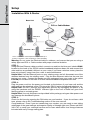
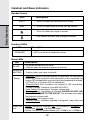
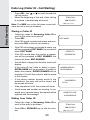
Parts Check List
The system is an advanced Broadband cordless telephone set, capable of supporting four handsets.
This manual is designed to familiarize you with this Broadband cordless telephone.
We strongly recommend you read the manual before using your phone.
6. Charger Wall Mounting Brackets
1. Base Unit
7. Belt Clip(s)
2. Handset(s)
8. User Documentation CD
3. Handset Charger(s)
9. Quick Start Guide
4. Ethernet Cables
10.Battery(ies)
5. Base Power Adapter
Note: Use ONLY VTech battery 80-5808-00-00 or VTech replacement
89-1324-00-00.
Base Unit
Battery
Handset
Blue Ethernet Cable
Base AC Adapter
Handset Charger
Yellow Ethernet Cable
Belt Clip
Charger Wall
User Documentation CD Quick Start Guide Mounting Bracket
Note: If you have purchased the IP8100 series telephone, please also refer to
the parts list in your IP811 user’s manual.
The Handset Layout
12
13
16
1.
2.
3.
4.
5.
6.
7.
8.
9. Speakerphone
10.LCD Display
11.Select (Menu)
12.Phonebook (Scroll Up)
13.Headset Jack (2.5mm)
14.Off (Clear)
15.Intercom
16.Mute (Delete)
Antenna
Earpiece
Volume Control
CID (Scroll Down)
On (Flash)
Voicemail
Dialing Keys (0-9, *, #)
Redial (Pause)
The Base Unit Layout
1.
2.
3.
4.
5.
6.
7.
8.
Message Waiting LED
Page key
In Use LED
Service Status LED
LAN Port
WAN Port
DC Connector Jack
Reset Switch
Getting Started
Setup
Connecting power to Base Unit/Handset Charger
1. Plug the power adapter into an electrical
outlet, and the connector into the connector jack at the bottom of the base unit.
2. Choose the location for your handset charger,
and plug its power supply into an electrical
outlet.
Installation of Battery Pack in Handset
Follow the steps below:
1. Remove the battery compartment
cover by pressing on the indentation
and sliding downward. Place the new
battery pack in the handset with the
positive and negative poles aligned in
the battery compartment.
2. Replace the battery cover by sliding it
upwards.
3. If the new battery pack is not already
charged, place the handset in its
charger, and allow it to charge for
10-12 hours. After initial charge, a
maintenance charge of 8 hours should
be sufficient.
Charging of the Handset Battery Pack
The handset of your cordless telephone is powered by a rechargeable battery
pack. It charges automatically whenever handset is in its charger.
You should charge the batteries for 10-12 hours when you first receive your
phone. You will know the battery pack needs charging when:
• The low battery message is displayed:
• The handset seems completely dead, the LCD is
completely clear and does not activate when you
press the keys.
Note: While in PLACE IN CHARGER (low battery)
mode, the keypad sounds, backlighting and speakerphone features will not work. When the battery has been charged, the features
will return to their normal function.
IMPORTANT:
1. Do not dispose of the battery pack in a fire, it might explode.
2. Do not open or mutilate the battery pack. Toxic substances may be released, causing harm to eyes or skin.
3. Exercise care in handling batteries in order to prevent an accidental short of
the charge contacts, potentially causing the batteries to overheat.
4. Do not dispose of the battery pack into household garbage. Please refer to the
information concerning proper battery recycling.
5. Do not charge the battery pack with other electrical devices.
Reset Switch
The reset switch, when quickly pressed and released, will reset the phone and
restart the software. Beware that when the reset switch is pressed and held for
more than 10 seconds and then released, the phone will restore to factory defaults.
This includes clearing and resetting the password on the web configuration. Reset switch does not affect your base unit power, RF operation, or any of the
telephone handset settings.
Checking for dial tone
After the battery is charged, press ON on the handset. The LCD displays PHONE and
shows a call timer, and you will hear a dial tone. If not, see In Case of Difficulty.
CAUTION: Use only the VTech power supply provided with your telephone.
IMPORTANT! MAXIMUM PERFORMANCE OF YOUR CORDLESS TELEPHONE SYSTEM:
1. Install your base unit and extension
handsets away from electronic equipment, such as personal computers,
television sets and microwave ovens.
2. In locations where there are multiple
cordless telephones, separate the
base units as far away as possible.
3. Install your telephone equipment away
from heat sources and sunlight.
4. Avoid excessive moisture, dust or
extreme cold.
Add new handsets to make your phone more versatile
Your telephone can accommodate up to four cordless handsets. You can add
new handsets (Model IP811, sold separately) at any time. You can register a
maximum of four handsets.
Getting Started
Setup
Getting Started
Wall Mounting
The wall mount brackets are designed for use on standard wall mount plates
only. Wall mounting is optional. Only the handset chargers (not the main base
unit) can be wall mounted.
1. Plug the power adapters into electrical outlets, and the connector to the bottom of the handset charger.
2. Line up the tabs on the wall mount brackets with the holes at the back of the
handset charger. Snap the wall mount bracket firmly in place.
3. Mount the handset charger on the wall. Position the handset charger so the
mounting studs will fit into the holes on the wall mount bracket. Slide handset
charger down on the mounting studs until it locks into place.
Getting Started
Setup
Installation Without A Router
INTERNET
DSL or Cable Modem
PC
Handset 1 & 2
PC/LAN Port
WAN Port
Base Unit
NOTE: The IP8100 series telephone is
expandable up to a total of 4 handsets.
Uses model IP 811 (sold separately)
Warning: Do not route the Ethernet cable to outdoors, and ensure that you are
using a safety approved DSL or Cable modem with proper electrical isolation.
STEP 1
Unplug the power cord from your Cable or DSL modem (the device your ISP
provided which provides high-speed Internet). Make sure that you turn your
computer off and that you do NOT plug in your IP8100 series broadband telephone until instructed to do so.
Helpful Hint: The modem should be powered off for at least 10 minutes. If it is
turned off for a shorter period of time, it may “remember” old information that will
prevent it from working properly.
Getting Started
Setup
STEP 2
Disconnect all cables between your Cable or DSL modem and your computer.
STEP 3
Connect one end of the yellow Ethernet cable to the yellow port, labeled “PC/
LAN,” located on the back of the base unit and connect the other end of the yellow cable to the Ethernet port of your computer.
STEP 4
Connect one end of the blue Ethernet cable to the blue port, labeled “WAN,”
located on the back of the base unit and connect the other end of the blue cable
to the Ethernet port on your cable or DSL modem.
STEP 5
Reconnect power cord to the modem then turn the modem on. Please wait until
all lights on the modem stop blinking.
Helpful Hint: This should take a few minutes, but may take as long as 10 minutes.
STEP 6
Plug the power cord into the power port located on the bottom or your IP8100
series telephone and the other end into the electrical outlet. This turns the IP
8100 series broadband telephone on.
Helpful Hint: DO NOT interrupt this registration process by unplugging the power or by using the handsets until the READY indicator light on the front of IP8100
series base has gone from flashing yellow to a steady green.
Helpful Hint: Use only the power cord provided in this package; using an older
power cord can damage the broadband telephone.
STEP 7
Turn your computer on, and check your computer to see if your Internet is working, try to visit any website. If your Internet is working, please proceed to STEP
10. If not, please proceed to STEP 8.
STEP 8:
Cable Users
If you receive Internet access through a Cable modem, you may need to register
the IP8100 series telephone with your ISP. Please contact them to update your
information; you will likely need your WAN MAC address, which is located on
the bottom of the IP8100 series telephone. Once your ISP has updated your
account, proceed to step 9.
-- OR --
DSL Users
If you have DSL and are required to enter a user name and password (PPPoE)
when accessing the Internet, you may be required to authenticate the IP8100
series telephone.
A.
B.
C.
Open a web browser such as Microsoft ® Internet Explorer using the computer connected through your phone Ethernet port. In the address of location field, type <http://192.168.15.1> and press ENTER. This displays the login screen. Enter the default password ‘VTech’ and click on login.
On the Setup Wizard screen, click Run Wizard to start the set-up.
Follow Wizard screens to complete the setup.
STEP 9:
Check for dial tone by pressing the ON button on your handset. If you do not hear
a dial tone, please refer to the Troubleshooting section of the user manual.
Congratulations! Even if you are transferring your number, you are ready to start
taking advantage of the great savings and superior quality of Vonage right now!
Please call 800-342-1791 to setup your voicemail service and to learn about
other free Vonage features included with every Vonage calling plan.
Getting Started
Setup
Getting Started
Setup
Installation With A Router
Base Unit
INTERNET
DSL or Cable Modem
PC
WAN Port
Laptop
Handset 1 & 2
Existing
Network Router
NOTE: The IP8100 series telephone is expandable up to
a total of 4 handsets. Uses model IP 811 (sold separately)
Warning: Do not route the Ethernet cable to outdoors, and ensure that you are using a
safety approved DSL or Cable modem with proper electrical isolation.
STEP 1:
Using the blue Ethernet cable provided, connect one end into the blue port, labeled WAN,
located on the back of the IP8100 series broadband telephone base unit and connect the
other end into an available LAN port on your router. If you have a wireless router, place the
base unit at least 3’ away from your router to avoid interference.
Helpful Hint: If all the Ethernet ports on your existing router are full, disconnect one of the
attached devices from the existing router. Plug the blue Ethernet cable into the now free
port on your router. Connect the device you just unplugged from your router to the yellow
PC/LAN port located on the back of IP8100 series broadband telephone base unit.
STEP 2:
Plug the power cord into the power port located on the bottom of your base unit and the
other end into the electrical outlet. This turns the IP8100 series broadband telephone on.
Helpful Hint: DO NOT interrupt this registration process by unplugging the power or by
using the handsets until the READY indicator light on the front of base has gone from
flashing yellow to a steady green.
Helpful Hint: Use only the power cord provided in this package; using an older power cord
can damage the broadband phone.
STEP 3:
Check for dial tone by pressing the ON button on your handset. If you do not hear a dial
tone, please refer to the Troubleshooting section of the user manual.
Congratulations! Even if you are transferring your number, you are ready to start taking
advantage of the great savings and superior quality of Vonage right now! Please call 800342-1791 to setup your voicemail service and to learn about other free Vonage features
included with every Vonage calling plan.
10
Getting Started
Setup
Installation With A Modem Router
INTERNET
Base Unit
PC
WAN Port
Laptop
DSL or Cable Modem
Handset 1 & 2
NOTE: The IP8100 series telephone is expandable up to
a total of 4 handsets. Uses model IP811 (sold separately)
Warning: Do not route the Ethernet cable to outdoors, and ensure that you are using
a safety approved DSL or Cable modem with proper electrical isolation.
STEP 1:
Using the blue Ethernet cable provided, connect one end into the blue port, labeled
“WAN,” located on the back of the IP8100 series broadband telephone base unit and
connect the other end into an available LAN port on your router. If you have a wireless modem router, place the base unit at least 3 feet away from your router to avoid
interference.
Helpful Hint: If all the Ethernet ports on your existing router are full, disconnect one
of the attached devices from the existing router. Plug the blue Ethernet cable into
the now free port on your router. Connect the device you just unplugged from your
router to the yellow “PC/LAN” port located on the back of IP8100 series broadband
telephone base unit.
STEP 2:
Plug the power cord into the power port located on the bottom of your base unit
and the other end into the electrical outlet. This turns the IP8100 series broadband
telephone on.
Helpful Hint: DO NOT interrupt this registration process by unplugging the power or
by using the handsets until the READY indicator light on the front of base has gone
from flashing yellow to a steady green.
Helpful Hint: Use only the power cord provided in this package; using an older power cord can damage the broadband phone.
STEP 3:
Check for dial tone by pressing the ON button on your handset. If you do not hear a
dial tone, please refer to the Troubleshooting section of the user manual.
Congratulations! Even if you are transferring your number, you are ready to start taking advantage of the great savings and superior quality of Vonage right now! Please
call 800-342-1791 to setup your voicemail service and to learn about other free Vonage features included with every Vonage calling plan.
11
Handset and Base Indicators
Handset Icons
Basic Operation
Icon
Description
MUTE
• Turns On when the microphone is muted.
NEW
• Turns On when there are new call log entries.
• Turns On when the ringer is muted.
• Low battery indicator and charging indicator.
Handset LEDs
LED
SPEAKER
Description
• LED is on when in handsfree mode.
Base LEDs
LED
Description
IN USE
• On when the phone is off hook.
• Flashes when an extension phone is off hook.
MESSAGE
• Flashes when you have voicemail.
WAITING
Ready
WAN/LAN
port
• Solid Red: Internet Service currently not available. No connection
to the ISP. Either (a) wait for the connection to be completed, (b)
ensure ISP configuration is correct (and user/password is entered,
if PPPoE), or (c) contact ISP for assistance.
• Flashing Red: Error condition not related to ISP connection.
Contact Vonage Customer Care 866-243-4357.
• Solid Yellow: Connecting to Vonage, please wait.
• Flashing Yellow: Connecting to Vonage PLEASE DO NOT UNPLUG THE POWER TO THE IP8100. This process may take a
few minutes, please wait.
• Solid Green: Line ready to use.
• Flashing Green: Software upgrade in progress, may make and
receive calls.
• Green: Link/activity indicator (off = no connection, on steady = connected, blinking = activity detected).
• Yellow: Connection speed indicator (off = 10Mb/s, on = 100Mb/s).
12
Handset Operation
• Press ON (or, SPEAKER to use the handset speakerphone feature). Dial the phone number.
-OR• Dial the phone number first; then press ON (or
SPEAKER).
• Press OFF to end your call.
Answering Calls
• Press ON, SPEAKER or any dialing keys.
• Press OFF to end your call.
If the handset is in idle mode during an incoming call,
the ringer can be temporarily muted by pressing OFF
or MUTE, or by adjusting the ringer volume using the
volume keys. If the ringing is muted completely (by
pressing OFF or MUTE, or adjusted to ringer level 0
using the volume keys), the ringer mute icon will turn
on indicating the ringing is being muted.
This feature is useful when you need to lower or stop the
ringing quickly without actually answering the call. For
example, someone is sleeping in the room and you want
to check the caller ID before answering, or you want to
ignore just the current call.
This adjustment is temporary, and only last for the
current ringing call. The ringer volume will return to it’s
normal setting once the call is answered or when the ringing stops.
Adjust the Handset Volume (also applies to the handset speakerphone
and headset)
• The volume control is on the left edge of the handset. During a call, press
VOLUME
or
keys to adjust the listening volume to a comfortable
level. When you reach the maximum or minimum setting, a double-beep will
sound.
Flash Function
• You can use your IP 8100-2/8100-3 with services
such as call waiting. When you receive a call waiting
signal, simply press the ON/FLASH key to switch
to the new call. Press ON/FLASH again to switch
back to the original call.
Redial Function
REDIAL
595-9511
• Press REDIAL/PAUSE to display the last telephone number dialed from the
handset (up to 32 digits). Use
or
to scroll through the five previously
dialed numbers. When the beginning or the end of the redial list is reached,
a double beep will sound.
• When the desired number is reached, press ON or SPEAKER to dial.
• Pressing OFF will exit the redial review list.
13
Basic Operation
Making Calls
Handset Operation
• When the desired entry displays, press DELETE. You’ll hear a confirmation
beep.
dial Vonage Voicemail
Basic Operation
press and hold #1 to dial Vonage voicemail.
Mute Function
• During an active call, pressing the MUTE/
DELETE key will disable the microphone.
MICROPHONE MUTED will display
briefly. The screen will display:
• Press MUTE/DELETE again to return to
normal two-way conversation. MICROPHONE ON will display briefly.
Intercom Call
• From the idle (off) mode, press INT. The
handset (HS1) will display:
ENTER HANDSET #
• Select a number of the handset to be
called. The display will show: CALLING
HANDSET X (Where X is the handset
number.)
• The other handset will ring and the screen
will display:
HANDSET X IS CALLING
• Press INT, PHONE, SPEAKER or any of
the dial pad keys on handset X to answer
the intercom call. The screens will display:
PHONE 00:00:15
MICROPHONE MUTE
ENTER
HANDSET #
CALLING
HANDSET X
HANDSET X
IS CALLING
INTERCOM
INTERCOM ENDED
• Press INT or OFF on either handset to
end the call.
Note: If handset X is out of range, or on an
external call, when HS1 attempts to intercom
it, the display of HS1 will show:
14
UNABLE TO CALL
TRY AGAIN
Handset Operation
Call Forward
• While on an external call, one handset (HS1)
can forward it to any other handset:
ENTER HANDSET #
• Enter the handset number you wish to forward, HS1 will display:
• HS X can press ON to answer the call.
Note: If HS X does not respond in about 30
seconds, the external call will be returned to
HS1 and the display will show:
If the returned call is not answered within 30
seconds, the external call will end automatically.
CALL FORWARDED
CALL BACK
Conference Call
It is possible to establish a conference between
two handsets and the external line.
If a handset already has a connection to the
external line, and another handset goes offhook, a conference is immediately established.
Both handsets will show:
Base Operation
From the base unit, you can use the PAGE key
to locate the handsets.
• When the handset is in idle, press PAGE.
The handsets will display:
• To end the page at the handset, press ON,
SPEAKER or any dialing keys.
• To end the page at the base, press PAGE.
15
CONF. 00:00:25
BASE IS
PAGING
Basic Operation
• Press INT on HS1, it will display:
Phonebook Operation
Your phone can store up to 50 numbers with names in memory. Each memory location
can hold up to 32 digits for the number and 16 characters for the name.
Basic Operation
Note: The handsets share a common phonebook, which is stored in the base. This
means that entries inserted by one handset are available for all handsets, and if one
deletes a phonebook entry, it will disappear from all handsets.
When one handset is accessing the phonebook, the other handsets cannot access it
at the same time. If this is attempted, NOT AVAILABLE AT THIS TIME will display.
Storing a New Entry
• Press MENU.
• With PHONEBOOK highlighted, press
SEL.
to select STORE. Press
• Press
SEL.
• You will be prompted to ENTER
NUMBER. Use the dialing keys to enter
the number you wish to store in the
phonebook. Press the MUTE/DELETE
key to backspace and make corrections.
Press SEL.
• You will then be prompted to ENTER
NAME. Use the dialing keys to spell the
name. Press SEL.
• You will hear a confirmation tone, and
the new phonebook entry will display
briefly.
>STORE
REVIEW
ENTER NUMBER
800-595-9511
ENTER NAME
_
Notes:
• If the phonebook is full, the handset will
display PHONEBOOK IS FULL.
• You can also press REDIAL/PAUSE
then
or
to scroll to the previously
dialed number from the redial list
you want to store in the phonebook.
Pressing SEL will append the selected
redial number to the current editing
number.
• While entering numbers, press and
hold REDIAL/PAUSE to add pauses if
necessary.
• If there is a duplicate number in the
phonebook, the display will show:
16
PHONEBOOK
IS FULL
NUMBER ALREADY
IN PHONEBOOK
Phonebook Operation
Each press of a particular key causes characters to be displayed in the following
order:
1
2
3
4
5
6
7
8
9
0
*
#
1
2
Characters by number of key presses
3
4
5
6
7
8
9
r
s
y
z
space1
A
B
C
2
a
b
c
D
E
F
3
d
e
f
G
H
I
4
g
h
i
J
K
L
5
j
k
l
M
N
O
6
m
n
o
P
Q
R
S
7
p
q
T
U
V
8
t
u
v
W
X
Y
Z
9
w
x
0
*
#
?
!
/
(
)
‘
,
-
.
&
Reviewing/Dialing from the Phonebook
•
•
Press MENU. With PHONEBOOK in the first line,
press SEL. With the REVIEW in the first line, press
SEL again.
- OR and the handset
With the handset idle, press
jumps directly into the phonebook review mode.
The first phonebook entry will be displayed.
Scroll through the phonebook entries using
or
keys or enter first character of the name to
be searched (using the digit keys) and continue
scrolling using the and keys, until you reach
the entry to be dialed.
Note: When reviewing the phonebook, the second
line of the display will show the phone number, up
to 16 digits. For numbers longer than 16 digits,
only the first 13 digits will be shown. Press
or
# to scroll the phone number to see the additional
digits.
• Press ON or SPEAKER, to dial the number.
Note: If there are no entries in the phonebook, when it
is accessed, PHONEBOOK IS EMPTY will display.
17
VTech
595-9511
VTech Com
800-595-9511
PHONE 00:00:10
VTech Com
VTech Com
800-595-9511
Basic Operation
Key
Phonebook Operation
Editing a Phonebook Entry
Basic Operation
• Follow the first two steps in Reviewing/Dialing
from the phonebook (on previous page) to
reach the entry to be edited.
• Press SEL.
•
Press MUTE/DELETE to backspace then enter
the correct number. Press and hold REDIAL/
PAUSE to add pauses if necessary.
You can also press REDIAL/PAUSE, then
or
to scroll to the previously dialed number
from redial list which you want to store in the
phonebook. Pressing SEL will append the
selected redial number to the current editing
number.
•
Press SEL to confirm the number and enter
name edit mode.
•
Press MUTE/DELETE to backspace and use
the digit keys to enter the correct name.
•
Press SEL to confirm the change. A confirmation
tone will sound.
EDIT NUMBER
800-595-9511_
EDIT NAME
VTech_
VTech
595-9511
Delete a Phonebook Entry
•
Follow the first two steps in Reviewing/Dialing
from the Phonebook on previous page to
reach the entry to be deleted.
•
Press MUTE/DELETE to delete the entry.
A confirmation tone will sound.
•
The handset will then move to the next entry,
if any.
18
VTech Com
800-595-9511
VTech
595-9511
Calls Log (Caller ID - Call Waiting)
Your phone is capable of displaying the name and/or number of the party calling
before you answer the phone (caller ID). It is also capable of displaying caller
ID information in conjunction with a call waiting alert signal (call waiting caller
ID). With call waiting caller ID, the caller ID data is displayed so you can decide
whether to answer the incoming call, or continue with your current conversation.
Your phone can hold up to 50 CID entries.
These are subscription services, provided by Vonage.
When one handset is accessing the call log, the other handsets can not
access it at the same time. If this is attempted, NOT AVAILABLE AT THIS
TIME will display.
Due to regional incompatibilities, caller ID information may not be available
for every call you receive. In addition, the calling party may intentionally block
their name and/or phone number from being sent.
• As new caller ID/call waiting ID records are
received, your handset displays will alert you
to the new caller ID records, for example:
• After you review all new caller ID records,
the NEW call indication will be turned off and
the screen will show:
• If the call log is full, the oldest entry is deleted
to make room for the new call. If the call log
is empty when you try to enter to call log review, the following message is displayed:
Reviewing Caller ID
You can review the caller ID record via the
menu, as described below or by pressing the
key in idle whereby the handset jumps directly
to the caller ID review.
• In idle mode, press MENU to enter the
menu.
• Press
key to scroll to CALL LOG.
19
HANDSET 1
5 NEW CALLS
NEW
HANDSET 1
CALL LOG
IS EMPTY
>CALL LOG
RINGER VOLUME
Basic Operation
Caller ID - Call Waiting ID
Calls Log (Caller ID - Call Waiting)
Basic Operation
• Press SEL. Use
or
to scroll through the
call log entries.
• When the beginning or the end of the call log
is reached, a double beep will sound.
Note: The NEW icon in the left down corner indicates the call is not yet reviewed.
VTech Com
800-595-9511
NEW 2/23 11:59AM
Storing a Caller ID
• Follow the steps in Reviewing Caller ID to
scroll to the record to be stored.
• Press SEL.
• If the CID record contains both name and number, press SEL to store it into memory.
• If the CID record does not contain a name, you
will be prompted to EDIT NAME, the screen will
show: EDIT NAME.
• If the CID record does not contain a number,
you will be prompted to EDIT NUMBER, the
screen will show: EDIT NUMBER.
EDIT NAME
-
ADDED TO
PHONEBOOK
• You will hear a happy tone then the screen will
display:
• If the caller ID isn’t able to detect a name,
ENTER NAME will be prompted. If unable to
detect the number, ENTER NUMBER will be
prompted. You will then need to add the name
or the number.
• If the phone number already exists in the
phonebook, the entry will not be stored, and
the screen will show:
NUMBER ALREADY
IN PHONEBOOK
PHONEBOOK
IS FULL
• If the phonebook is full, the screen will show:
• If both name and number are missing, for example as in a private listing, the request will be
rejected with the message:
UNABLE TO SAVE
IN PHONEBOOK
Dialing from Caller ID
• Follow the steps in Reviewing Caller ID to
scroll to the entry to be dialed.
• Press ON or SPEAKER key to dial the number.
20
VTech Com
800-595-9511
NEW 2/23 11:59AM
Calls Log (Caller ID - Call Waiting)
Deleting Caller ID
• Press DELETE key to delete the desired record. A confirmation tone will sound and the
previous caller ID record will be displayed on
the screen.
• To delete all the caller ID records, press and
hold the DELETE key. The screen will ask
you DELETE ALL CALLS? Press SEL for
confirmation. Or, press OFF to return to the
CID record previously displayed.
21
VTech Com
800-595-9511
NEW 2/23 11:59AM
DELETE ALL
CALLS
Basic Operation
• Follow the steps in Reviewing Caller ID to
scroll to the record to be deleted.
Handset Settings
Ringer Volume
Basic Operation
• From the idle (off) mode, press MENU then
or
key to RINGER VOLUME.
• Press SEL. The current ringer volume will
be shown:
• Press
and
keys or enter digit 0-6 to the
desired ringer volume. The current ring tone
is played and the volume bar is increased/
decreased each time the setting is adjusted.
At the lowest setting, display will show:
• The handset will not ring when a call comes
in if ringer volume is set to the lowest setting.
• Press SEL to confirm the setting.
Ringer Tone
>RINGER VOLUME
RINGER TONE
RINGER VOLUME
RINGER VOLUME
>RINGER TONE
KEY TONE
• From the idle (off) mode, press MENU then
or
key to RINGER TONE.
• Press SEL. You will be prompted to choose
INTERCOM CALL or OUTSIDE CALL.
Press
or
to select the desired option.
• Press SEL again. You can then use
or
or enter digit 0-9 to sample the ring tones.
The screen, will show:
• Press SEL to confirm your setting.
>INTERCOM CALL
OUTSIDE CALL
>INTERCOM TONE
1
Key Tone (preset to ON)
• From the idle (off) mode, press MENU then
or
to KEY TONE. • Press SEL. The current setting will be shown.
Press
or
to scroll to ON or OFF. When
set to on, the handset will emit a beep whenever a key is pressed.
• When the desired option is shown, press
SEL to confirm your selection.
22
>KEY TONE
LANGUAGE
KEY TONE
OFF
Handset Settings
Language (preset to English)
• Press SEL to select this option. Press
or
to scroll from English to French or Spanish. • Press SEL to confirm the setting.
>LANGUAGE
CLEAR MSG WAIT
LANGUAGE
FRENCH
Message Waiting
Your phone is capable of detecting a message
waiting signal generated by Vonage.
Once you have reviewed all new messages,
the message waiting alert will automatically be
turned off.
Clear Message Waiting
If, after reviewing all new voicemail messages, the
message waiting alert still remains on the screen
and the MESSAGE WAITING LED on base is still
flashing, you can manually remove the indication
from the screen and turn the LED off.
>CLEAR MSG WAIT
DIAL TYPE
• From the idle (off) mode, press MENU then
or
to CLEAR MSG WAIT.
• Press SEL then the display will ask you TURN
INDICATOR OFF? Press SEL again to confirm. To exit, press OFF.
23
TURN INDICATOR
OFF?
Basic Operation
• From the idle (off) mode, press MENU then
or
key to LANGUAGE.
Headset Operation
Your IP8100 series handset is equipped with a 2.5mm headset jack for use with
an optional accessory headset for handsfree operation. If you choose to use the
headset option, you must obtain an optional accessory headset, which is compatible with the IP8100 series telephone.
To purchase a headset, visit us on the web at www.vtechphones.com
Once you have a compatible 2.5mm headset, locate the headset jack on the IP
8100 series handset. Connect the plug on the headset cord to the jack (under a
small rubber flap) on the cordless handset. The plug should fit securely. Do not
force the connection.
Advanced Operation
NOTE:
• Whenever a compatible headset is
connected to the cordless handset,
the microphone on the handset will be
muted. This is done to limit the effect
of background noise.
• When a compatible headset is connected to the cordless handset, your
speakerphone feature will be disabled.
To use your speakerphone feature,
simply disconnect the headset from
the handset.
Belt Clip
The IP8100 series telephone is also
equipped with a detachable belt clip. Align
the pins on the inside edge of the clip with
the notches on the sides of the handset.
The belt clip should snap securely into
place. Do not force the connection.
24
Troubleshooting
How do I access the web - base d configuration for the IP810 0 series
telephone?
It is important that you have the latest patches and bug fixes for your web browser
when attempting to connect to the configuration for your telephone adapter.
We recommend using the following:
Internet ExplorerTM 5.5 or higher
Netscape 6 or higher
Firefox 0.8 or higher
Use the following steps to gain access to the web-based configuration of your
IP8100 series telephone:
Step 1: Verify physical connectivity by checking for solid link lights on the phone
adapter. The computer that was able to access the Internet when connected to
the broadband modem or router should be connected to the PC port on the
IP8100 series. If you do not get a solid link, try using a different cable. If the
computer is turned off, the link light may not be on.
Step 2: Disable any Internet security software running on the computer. Software firewalls such as Zone Alarm, Black Ice, Sygate, Norton Personal Firewall,
and Windows XP firewall may block access to the configuration pages. If you
have DSL and use a PPPoE client such as WinPoet or EnterNet300, you should
disable this software as well. Check the help files included with these software
applications for more information on disabling or configuring them.
Step 4: Configure the Internet settings for your browser:
Go to Start > Settings > Control Panel. Double-click the Internet Options Icon.
From the Security tab, click the button to restore the settings to their defaults. If
this button is grayed out, then the settings are already at default.
Click the Connection tab. Set the dial-up option to Never Dial a Connection and
then click the LAN Settings button.
Verify that none of these settings are checked and then click OK.
Go to the Advanced tab and click the button to restore these settings to their
defaults.
Click OK out to the desktop and close any open windows.
25
Additional Information
Step 3: Check the IP address of your computer. Your computer must have an
IP address in the same range as the router in order to communicate with it,
192.168.15.X (X = 2-254). Included in the troubleshooting section of this manual
is more detailed information on checking your IP address.
Troubleshooting
Step 5: Access the web-based configuration of the IP8100 series telephone.
Open your web browser and enter http://192.168.15.1 (do NOT type www), in
the address bar. Use the instructions that were provided with the IP8100 series
telephone to complete the configuration as needed. Specifically, you will need to
configure the WAN settings to connect the device to the Internet.
How do I configure TCP/IP settings for my computer to connect to the IP
8100 series telephone?
Note: The following information assumes the computer is connected to the PC
Port on the IP8100 series telephone.
Win98/ME:
Step 1: From the Desktop, right-click the Network Neighborhood icon (My Network Places in WinME), and then select Properties.
Step 2: Highlight TCP/IP and then click the Properties button. If you have more
than one adapter installed, then there will be a TCP/IP entry for each adapter.
Highlight TCP/IP > [your network adapter] and then click Properties.
Additional Information
Step 3: Make sure the IP Address tab is selected. Configure the adapter to
Obtain an IP address. Then, Click OK out to the desktop to apply the changes.
Reboot the computer when prompted. When the computer reboots it should request, and obtain, a valid IP address from the IP8100 series telephone. Included
in the troubleshooting section of this manual is more detailed information on
checking your IP address.
Win2k/XP:
Step 1 - Win2k: From the Desktop, right-click the My Network places and then
select Properties.
Step 1 - WinXP: Click on Start > Control Panel > Network and Internet Connections > Network connections.
Step 2: Right-click on the Local Area Connection which represents your network card and then select Properties.
Step 3: Highlight Internet Protocol (TCP/IP) and click Properties.
Step 4: Configure the adapter to Obtain an IP address. Then, Click OK out to
the desktop to apply the changes and reboot the computer when prompted. If
you are not prompted to reboot the computer, you may need to renew the IP address of the computer manually. Included in the troubleshooting section of this
manual is more detailed information on checking your IP address.
26
Troubleshooting
How do I check my computer’s IP address?
Note: The following information assumes the computer is connected to the PC
port on the IP8100 series telephone. It also assumes the computer’s TCP/IP settings are configured to obtain an IP address automatically. Included in the troubleshooting section of this manual is more detailed information on configuring
your TCP/IP settings.
Win98/ME:
Step 1: Go to Start > Run and enter winipcfg. Click OK.
Step 2: From the dropdown menu, choose the Ethernet adapter.
Step 3: After selecting the adapter, it will display the IP settings. Your adapter
should have an IP address in the same range as the IP8100 series telephone,
192.168.15.X. If it doesn’t try releasing, then renewing the IP.
a. Click the Release button to release the IP address.
b. Click the Renew button to obtain a new address.
If you are unable to obtain a valid IP address, confirm that you have a good
physical connection between the computer and the IP8100 series telephone.
Step 4: Click OK to close the IP configuration window.
Win2k/XP:
Step 1: Go to Start > Run and enter cmd. Click OK.
Step 3: It will return your IP address, Subnet Mask, and Default Gateway. Your
adapter should have an IP address in the same range as the IP8100 series telephone,192.168.15.X. If it doesn’t try releasing, then renewing the IP.
a. Enter ipconfig/release to release the IP address.
b. Enter ipconfig/renew to obtain a new address.
If you are unable to obtain a valid IP address, confirm that you have a good
physical connection between the computer and the IP8100 series telephone.
Step 4: Type, exit and then click Enter to close the Command prompt.
27
Additional Information
Step 2: From the Command prompt, enter ipconfig and then click Enter.
Troubleshooting
I followed the Quick Start Guide for DSL, but I wasn’t able to successfully
configure the IP8100 series telephone. What else can I do?
If your DSL provider uses PPPoE, confirm that you have entered the correct
username and password in the IP8100 series telephone PPPoE settings. You
may need to append your ISP’s domain suffix to your username in order to connect. For example:
[email protected]
[email protected]
[email protected]
Contact your ISP if you are unsure of your username or password.
Additional Information
Some DSL providers will issue a Dynamic IP address without using PPPoE for
authentication. If this is the case for your provider, use the setup wizard in the
IP8100 series telephone web-based configuration to configure the WAN type
to use a Dynamic IP Address. Once you have applied that setting, power down
your broadband modem and the IP8100 series telephone. Power the modem on
first and let it stabilize. When the modem is ready, then power the IP8100 series
telephone on. Wait a few seconds for the device to stabilize, and then test your
connection.
I followed the Quick Start Guide for a Static IP, but I wasn’t able to successfully configure the IP8100 series telephone. What else can I do?
From the computer that was previously connected to the broadband modem,
access the web-based configuration for the IP8100 series telephone and clone
the MAC address. After the setting has been applied, power off the IP8100
series telephone. Wait about 30 seconds before reapplying the power. Wait a
few seconds for the device to stabilize, and then test your connection. If you still
cannot connect, confirm that you have entered all the IP information correctly.
Contact your ISP to confirm your IP address.
I followed Steps 1-6 in the Quick Start Guide, but I wasn’t able to successfully configure the IP8100 series telephone. What else can I do?
If you didn’t need to complete step 7, then it is assumed that your ISP is issuing
you a Dynamic IP address. From the computer that was previously connected
to the broadband modem, access the web-based configuration for the IP8100
series telephone and clone the MAC address. After the setting has been applied, power off the IP8100 series telephone. Wait about 30 seconds before
reapplying the power. Wait a few seconds for the device to stabilize, and then
test your connection.
28
Maintenance
Taking Care Of Your Telephone
Your cordless telephone contains sophisticated electronic parts, so it must be
treated with care.
Avoid rough treatment
Place the handset down gently. Save the original packing materials to protect
your telephone if you ever need to ship it.
Avoid water
Your telephone can be damaged if it gets wet. Do not use the handset outdoors
in the rain, or handle it with wet hands. Do not install your base unit near a sink,
bathtub or shower.
Electrical storms
Electrical storms can sometimes cause power surges harmful to electronic
equipment. For your own safety, use caution when using electric appliances
during storms.
Cleaning your telephone
Remember that electrical appliances can cause serious injury if used when you
are wet or standing in water. If your base unit should fall into water, DO NOT
RETRIEVE IT UNTIL YOU UNPLUG THE POWER CORD AND ETHERNET
CABLE FROM THE WALL. Then pull the unit out by the unplugged cords.
29
Additional Information
Your telephone has a durable plastic casing that should retain its luster for many
years. Clean it only with a soft cloth slightly dampened with water or a mild soap.
Do not use excess water or cleaning solvents of any kind.
Warranty Statement
What does this limited warranty cover?
• The manufacturer of this VTech product, VTech Communications, warrants to
the holder of a valid proof of purchase (“Consumer” or “you”) that the product
and all accessories provided by VTech in the sales package (“Product”) are free
from material defects in material and workmanship, pursuant to the following
terms and conditions, when installed and used normally and in accordance
with operation instructions, This limited warranty extends only to the Consumer
for Products purchased and used in the United States of America.
What will VTech Communications do if the Product is not free from
material defects in materials and workmanship during the limited
warranty period (“Materially Defective Product”)?
• During the limited warranty period, VTech’s authorized service representative
will repair or replace at VTech’s option, without charge, a Materially Defective
Product. If we repair this product, we may use new or refurbished replacement
parts. If we choose to replace this product, we may replace it with a new or
refurbished product of the same or similar design. VTech will return repaired or
replace ment products to you in working condition. VTech will retain defective
parts, modules, or equipment. Repair or replacement of Product, at VTech’s
option, is your exclusive remedy. You should expect the repair or replacement
to take approximately 30 days.
Additional Information
How long is the limited warranty period?
• The limited warranty period for the product extends for ONE(1) YEAR from
the date of purchase if we repair or replace a Materially Defective Product
under the terms of this limited warranty. This limited warranty also applies to
repaired or replacement Products for a period of either (a) 90 days from the
date the repaired or replacement Product is shipped to you or (b) the time
remaining on the original one-year warranty; whichever is longer.
What is not covered by this limited warranty?
This limited warranty does not cover
1. Product that has been subjected to misuse, accident, shipping or other physical damage, improper installation, abnormal operation or handling, negligent,
inundation, fire, water or other liquid intrusion; or
2. Product that has been damaged due to repair, alteration or modification by
anyone other than an authorized service representative of VTech; or
3. Product to the extent that the problem experienced is caused by signal conditions, network reliability or cable or antenna systems; or
4. Product to the extent that the problem is caused by use with non-VTech
electrical accessories; or
5. Product whose warranty/quality stickers, Product serial numbers plates or elec-
30
Warranty Statement
tronic serial numbers have been removed, altered or rendered illegible; or
6. Product purchased, used, serviced, or shipped for repair from outside the United States, or used for commercial or institutional purposes (including but
not limited to Products used for rental purposes); or
7. Product returned without valid proof of purchase (see 2 below); or
8. Charges for installation or set up, adjustment of customer controls, and installation or repair of systems outside the unit.
How do you get warranty service?
•
To obtain warranty service in the United States of America, call 1- 800-5959511 for instructions regarding where to return the Product. Before calling for
service, please check the user’s manual. A check of the Product controls and
features may save you a service call.
• Except as provided by applicable law, you assume the risk of loss or damage
during transit and transportation and are responsible for delivery or handling
charges incurred in the transport of Product(s) to the service location. VTech
will return repaired or replaced product under this limited warranty to you,
transportation, delivery or handling charges prepaid. VTech assumes no risk
for damage or loss of the Product in transit.
• If the Product failure is not covered by this limited warranty, or proof of purchase
does not meet the terms of this limited warranty, VTech will notify you and will
request that you authorize the cost of repair and return shipping costs for the
repair of Products that are not covered by this limited warranty.
1. Return the entire original package and contents including the Product to the VTech service location along with a description of the malfunction or difficulty;
2. Include “valid proof of purchase” (sales receipt) identifying the Product
purchased (Product model) and the date of purchase or receipt; and
3. Provide your name, complete and correct mailing address, and telephone number.
Other Limitations
• This warranty is the complete and exclusive agreement between you and
VTech. It supersedes all other written or oral communications related to this
Product. VTech provides no other warranties for this product. The warranty
exclusively describes all of VTech’s responsibilities regarding the product. There are no other express warranties. No one is authorized to make modifications
to this limited warranty and you should not rely on any such modification.
State Law Rights: This warranty gives you specific legal rights, and you may also
have other rights, which vary from state to state.
31
Additional Information
What must you return with the Product to get warranty service?
Warranty Statement
Limitations: Implied warranties, including those of fitness for a particular purpose
and merchantability (an unwritten warranty that the product is fit for ordinary
use) are limited to one year from date of purchase. Some states do not allow
limitations on how long an implied warranty lasts, so the above limitation may
not apply to you.
Additional Information
• In no event shall VTech be liable for any indirect, special, incidental, consequential, or similar damages (including, but not limited to lost profits or
revenue, inability to use the product, or other associated equipment, the cost
of substitute equipment, and claims by third parties) resulting from the use of
this product, some states do not allow the exclusion or limitation of incidental
or consequential damages, so the above limitation or exclusion may not apply
to you.
32
Important Safety Instructions
1. Read and understand all instructions.
2. Follow all warnings and instructions marked on the product.
3. Unplug this product from the power outlet and broadband connection before
cleaning. Do not use liquid cleaners or aerosol cleaners. Use a damp cloth
for cleaning.
4. Do not use this product near water (for example, near a bath tub, kitchen sink, or swimming pool).
5. Do not place this product on an unstable cart, stand, or table. The product
may fall, causing serious damage. 6. Slots and openings on the base and handset are provided for ventilation.
To protect it from overheating, these openings must not be blocked by placing the product on the bed, sofa, rug, or other similar surface. This product
should never be placed near or over a radiator or heat register. This product
should not be placed in a built-in installation where proper ventilation is not
provided.
7. This product should be operated only from the type of power source indicated
on the marking label. If you are not sure of the type of power supply to your
home, consult your dealer or local power company.
8. Do not allow anything to rest on the power cord. Do not locate this product
where the cord will be abused by persons walking on it.
9. Never push objects of any kind into this product through the slots in the base
or handset as they may touch dangerous voltage points or short out parts that
could result in a risk of fire or electric shock. Never spill liquid of any kind on
the product.
10.To reduce the risk of electric shock, do not disassemble this product, but take
it to an authorized service facility. Opening or removing cabinet parts other
than specified access doors may expose you to dangerous voltages or other
risks. Incorrect reassembling can cause electric shock when the appliance is
subsequently used.
11.Do not overload wall outlets and extension cords as this can result in the risk
of fire or electric shock.
12.Unplug this product from the wall outlet and contact VTech under the following
conditions:
A. When the power supply cord or plug is damaged or frayed.
B. If liquid has been spilled into the product.
C. If the product has been exposed to rain or water.
D. If the product does not operate normally by following the operating instructions. Adjust only those controls that are covered by the oper-
ating instructions, because improper adjustment of other controls may result in damage and will often require extensive work to restore the product to normal operation.
33
Additional Information
When using your telephone equipment, basic safety precautions should always
be followed to reduce the risk of fire, electric shock and injury, including the following:
Important Safety Instructions
E. If the product has been dropped and the handset and/or base unit has been damaged.
F. If the product exhibits a distinct change in performance.
13.Avoid using a telephone (other than cordless) during an electrical storm. There
may be a remote risk of electric shock from lightning.
14.Do not use this or any cordless telephone to report a gas leak in the vicinity
of the leak.
15.Use only the power cord and batteries indicated in this manual. Do not dispose
of batteries in a fire. They may explode. Check with local codes for possible
special disposal instructions.
SAVE THESE INSTRUCTIONS
Additional Information
BEFORE USING YOUR IP8100 SERIES SYSTEM, CAREFULLY PEEL OFF
THE PROTECTIVE FILM COVERING THE DISPLAYS.
34
FCC and IC Regulations
This equipment complies with Parts 15 of the Federal Communications Commission (FCC) rules for the United States. It also complies with regulations
RSS210 of Industry and Science Canada. Operation is subject to the following
two conditions: (1) this device may not cause interference, and (2) this device
must accept any interference, including interference that may cause undesired
operation of the device.
FCC Part 15
Warning: Changes or modifications to this unit not expressly approved by the
party responsible for compliance could void the user’s authority to operate the
equipment.
The equipment has been tested and found to comply with part 15 of the FCC
rules. These limits are designed to provide reasonable protection against harmful
interference in a residential installation. This equipment generates, uses and can
radiate radio frequency energy and, if not installed and used in accordance with
the instructions, may cause harmful interference to radio communications.
However, there is no guarantee that interference will not occur in a particular
installation. If this equipment does cause harmful interference to radio or television reception, which can be determined by turning the equipment off and on,
the user is encouraged to try and correct the interference by one or more of the
following measures:
To ensure safety of users, the FCC has established criteria for the amount of radio
frequency energy that can be safely absorbed by a user or bystander according
to the intended usage of the product. This product has been tested and found to
comply with the FCC criteria. The handset has such a low power that it does not
require testing. It may be safely held against the ear of the user. The base unit shall
be installed & used such that parts of the user’s body other than the hands should
be maintained at a comfortable distance of approximately 20 cm or more.
IC (Industry Canada)
This telephone is registered for use in Canada.
The term “IC:” before the radio certification number only signifies that Industry
Canada technical specifications were met.
Before installing this equipment, users should ensure that it is permissible to be
connected to the facilities of the local telecommunications company. The equip-
35
Additional Information
• Reorient or relocate the receiving antenna.
• Increase the separation between the equipment and receiver.
• Connect the equipment into an outlet or on a circuit different from that to which
the receiver is connected.
• Consult the dealer or an experienced radio/TV technician for help.
FCC and IC Regulations
ment must also be installed using an acceptable method of connection. The
customer should be aware that compliance with the above conditions may not
prevent degradation of services in some situations.
Repairs to certified equipment should be made by an authorized Canadian maintenance facility designated by the supplier. Any repairs or alterations made by the
user to this equipment, or equipment malfunctions, may give the telecommunications company cause to request the user to disconnect the equipment.
Users should ensure for their own protection that the electrical ground connections of the power utility, telephone lines and internal metallic water pipe system,
if present, are connected together. This precaution may be particularly important
in rural areas.
Caution:
Users should not attempt to make such connections themselves, but should contact
the appropriate electrical inspection authority, or electrician, as appropriate.
Additional Information
Your cordless phone is designed to operate at the maximum power allowed by
the FCC and IC. This means your handset and base unit can communicate only
over a certain distance - which will depend on the location of the base unit and
handset, weather, and the construction and layout of your home or office.
36
Technical Specifications
FREQUENCY CONTROL
WEIGHT
Crystal controlled
PLL synthesizer
Handset: 146 grams
(excluding batteries)
Base: 323 grams
Charger: 225 grams
TRANSMIT FREQUENCY
Base: 5725 - 5850 MHz
Handset: 2400 - 2483.5 MHz
POWER REQUIREMENTS
RECEIVE FREQUENCY
Handset: 3.6V 600mAh NiMH
( battery pack)
Base: 5.1V, 1.7A
Charger: 9 V @ 150mA
Base: 2400 - 2483.5 MHz
Handset: 5725 - 5850 MHz
CHANNELS
95 Channels
MEMORY
NOMINAL EFFECTIVE RANGE
Maximum power allowed by FCC and
IC. Actual operating range may vary
according to environmental conditions
at the time of use.
SIZE
SPECIFICATIONS ARE TYPICAL
AND MAY CHANGE WITHOUT
NOTICE.
Additional Information
Handset: 182mm x 55.3mm x 40mm
(including antenna)
Base: 169.1mm x 60.7mm x 157.2mm
Charger: 76.5mm x 79.4mm x 45.2mm
Phonebook: 50 Memory locations;
up to 32 digits for number, 16 characters for name
CID: 50 Memory locations
37
Index
A
Installation With A Modem Router 11
Installation With A Router 10
Installation Without A Router 7
Intercom Call 16
Additonal Information 25-37
Adjust the Handset Volume 13
Advanced operation 24
Answering Calls 13
K
B
Key Tone (preset to ON) 22
Base LEDs 12
Base Operation 15
Basic Operation 12-23
C
Caller ID - Call Waiting ID 19
Call Forward 15
Calls Log (Caller ID - Call Waiting) 19
Charging of the Handset Battery Pack 4
Checking for dial tone 5
Conference Call 15
Connecting power to Base Unit/Handset Charger 4
L
Language (preset to English) 23
M
Maintenance 29
Making Calls 13
Message waiting 23
Mute Function 14
P
Parts Check List 1
Phonebook Operation 16
D
R
Delete a phonebook entry 18
Deleting Caller ID 21
Dialing from Caller ID 20
Dial Vonage Voicemail 14
Redial Function 13
Reset Switch 5
Reviewing/Dialing from the
phonebook 17
Reviewing Caller ID 19
Ringer tone 22
Ringer Volume 22
E
Editing a phonebook entry 18
F
S
SETUP 4
Storing a Caller ID 20
Storing a new entry 16
FCC and IC Regulations 35–36
Flash Function 13
H
Handset and Base Indicators 12
Handset Icons 12
Handset LEDs 12
Handset Operation 13
Handset Settings 22
Headset Operation 24
T
The Base Unit Layout 3
The Handset Layout 2
Troubleshooting 25–28
W
Wall Mounting 6
Warranty Statement 30–32
I
Important Safety Instructions 33
Installation of Battery Pack in Handset 4
38
VTECH TELECOMMUNICATIONS LTD.
A member of THE VTECH GROUP OF COMPANIES.
Distributed in the U.S.A. by VTech Communications, Inc. Beaverton,
Oregon
Distributed in Canada by VTech Telecommunications Canada Ltd.,
Richmond, B.C.
Copyright 2005 for VTECH TELECOMMUNICATIONS LTD.
Table Of Contents
Parts Check List................................................................................................. 1
The Handset Layout........................................................................................... 2
The Base Unit Layout......................................................................................... 3
Getting Started.......................................................................................... 4
SETUP................................................................................................................ 4
Connecting power to Base Unit/Handset Charger............................................. 4
Installation of Battery Pack in Handset............................................................... 4
Charging of the Handset Battery Pack............................................................... 4
Reset Switch...................................................................................................... 5
Checking for dial tone....................................................................................... 5
Wall Mounting..................................................................................................... 6
Installation Without A Router.............................................................................. 7
Installation With A Router ................................................................................ 10
Installation With A Modem Router ....................................................................11
Basic Operation........................................................................................ 12
Handset and Base Indicators........................................................................... 12
Handset Icons.................................................................................................. 12
Handset LEDs.................................................................................................. 12
Base LEDs....................................................................................................... 12
Handset Operation........................................................................................... 13
Making Calls..................................................................................................... 13
Answering Calls................................................................................................ 13
Adjust the Handset Volume.............................................................................. 13
Flash Function.................................................................................................. 13
Redial Function................................................................................................ 13
dial Vonage Voicemail...................................................................................... 14
Mute Function................................................................................................... 14
Intercom Call.................................................................................................... 14
Call Forward..................................................................................................... 15
Conference Call................................................................................................ 15
Base Operation................................................................................................ 15
Phonebook Operation...................................................................................... 16
Storing a new entry......................................................................................... 16
Reviewing/Dialing from the phonebook........................................................... 17
Editing a phonebook entry............................................................................... 18
Delete a phonebook entry................................................................................ 18
Calls Log (Caller ID - Call Waiting)................................................................... 19
Caller ID - Call Waiting ID................................................................................. 19
Reviewing Caller ID.......................................................................................... 19
Storing a Caller ID............................................................................................ 20
Dialing from Caller ID....................................................................................... 20
Deleting Caller ID............................................................................................. 21
Handset Settings.............................................................................................. 22
Ringer Volume.................................................................................................. 22
Ringer tone...................................................................................................... 22
Table Of Contents
Key Tone (preset to ON)................................................................................... 22
Language (preset to English)........................................................................... 23
Message waiting.............................................................................................. 23
Clear Message waiting..................................................................................... 23
Advanced Operation............................................................................... 24
Headset Operation........................................................................................... 24
Additional Information......................................................................... 25
Troubleshooting................................................................................................ 25
Maintenance..................................................................................................... 29
Warranty Statement.......................................................................................... 30
Important Safety InstructIONS......................................................... 33
FCC and IC Regulations.................................................................................. 35
Technical Specifications................................................................................... 37
Model: IP8100 series telephone