1
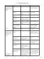
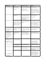
SERVICE MANUAL
(TROUBLE SHOOTING AND REPAIRING TIPS)
Fourth Edition – February 2006
CONSERV REFRIGERATOR
MODELS
375 / 1200 SERIES ( OLD & NEW)
WARRANTY INFORMATION
Your Equator appliance is protected by this warranty under normal,
personal, family or household use (1 Year), and limited commercial use
(90 days) in the USA and Canada.
WARRANTY SERVICE
WARRANTY
Equator Corporation undertakes to the consumer-owner This warranty is given by:
Equator Corporation,
to repair or, at Equator Corporation’s option, to replace
Equator Plaza,
any part of this product which proves to be defective in
2801 W. Sam Houston Pkwy. N.,
workmanship or material under normal personal, family
Houston, TX 77043-1611.
or household use, in the USA and Canada, for a period of
one year from the date of original purchase.
Service under this warranty must be obtained by the
For commercial use, the product is warranteed for a following steps, in order:
period of 90 days.
Call an Equator Corporation Authorized Service Agent
During this period, Equator Corporation will provide all (obtain number of nearest agent from your dealer or by
labor and parts necessary to correct such defect, free of c a l l i n g E q u a t o r S e r v i c e a t
charge, if the appliance has been installed and operated 1-800-776-3538). Under normal circumstances,
in accordance with Equator Corporation’s written Service will be provided during regular business hours
instructions with the appliance. Ready access to the (9:00 a.m. to 5:00 p.m. weekdays).
appliance, for service, is the responsibility of the
GENERAL
consumer-owner.
Since it is responsibility of the consumer-owner to
establish the warranty period by verifying the original
purchase date, Equator Corporation recommends that
EXCLUSIONS
In no event shall Equator Corporation be liable for a receipt, delivery slip or some other appropriate
incidental or consequential damages or for damages payment record be kept for that purpose.
resulting from external causes such as abuse, misuse,
Remember to send in your Warranty Registration Card
incorrect voltage or acts God.
so that a proof of your purchase exists with Equator.
This warranty does not cover service calls which do not This warranty gives you specific legal rights, and
involve defective workmanship or materials covered by you may also have other rights which vary from State to
this warranty. Accordingly, diagnosis and repair costs State.
for a service call which does not involve defective
Corporate Office
workmanship or materials will be the responsibility of the
consumer-owner.
EQUATOR CORPORATION
Equator Plaza
2801 W. Sam Houston Pkwy. N.
Specifically, the following work is not covered under
Houston, TX 77043-1611
Tel: 713-464-3422 - Fax: 713-464-2151
warranty and does not constitute warranty work:
Tel: 800-935-1955
. Installation
- improper hook-up or leveling
. Maintenance - cleaning of air and/or water filter
. Damage
- replacing broken door handle
Most work is covered. The defining factor is, has the
machine malfunctioned (Equator is responsible) or has
the customer omitted or done something to cause
machine to malfunction (customer is responsible).
Some States do not allow the exclusion or limitation of
incidental or consequential damages, so the above
limitation or exclusion may not apply to you.
1.
2.
1.1 Trouble-Shooting Chart
Disturbance
Cause
Unit does not
Wall socket is dead.
refrigerate or freeze,
compressor does not
operate.
Mains cable is
defective.
Trouble-Shooting
Check installation.
Remedy
Install new fuse if
necessary. Inform user.
See section 1.2: Trouble- Repair or replace socket
shooting in the electrical or mains cable.
circuit.
Replace thermostat.
Thermostat is
defective.
Defective winding in See section 1.6: Trouble- Replace compressor.
compressor.
shooting for Electrical
Faults in the Compressor.
Starting device is
defective.
No-Frost
See section 1.2: trouble
shooting in the Electric
circuit.
Correct in accordance
with wiring diagram in
the spare parts list.
Turn timer knob past
defrosting.
Wiring for starting
device is incorrectly
installed.
Timer is set in
defrosting position.
Insufficient mains
Unit does not
refrigerate or freeze, voltage.
compressor tries to
start but fails to
operate.
Wrong or defective
starting device.
Check mains voltage.
Inform user that
installation should be
repaired by an electrician.
See section 1.2:
Troubleshooting in the
Electric Circuit.
Install new starting
device.
Correct according to
wiring diagram in the
spare parts list.
Wiring for starting
device is incorrectly
installed.
Winding fault in
compressor.
To be continued on
the next page
Replace starting device.
See section 1.5:
Troubleshooting for
Electrical Faults in the
compressor.
Replace compressor.
Condensing pressure Open system and location Remove filter drier and
too high (obstruction obstruction by blowing cut 5 cm of the capillary
N2 through system. See tube. Blow through the
capillary tube).
Section 2.1: Opening the system thoroughly before
Refrigerating System with installing new filter.
R600a for Repairs.
3.
D isturbance
Cause
O il present in system
after horizontal
transport.
Trouble -Shooting
Q uestion user about mode
of transportation and time
interval between
installation and start-up.
Locked rotor (fault in Check that compressor
compressor).
hums and picks up total
starting current. O pen
system and blow N 2
through system.
Ambient temperature Measure ambient
temperature. Measure
very low. O il in
compressor too cold, voltage.
possibly in connection
with undervoltage.
R e me dy
Let unit stand for several
hours at warm
temperature and try to
start again. If compressor
does not start, open the
system and blow through
with N 2.
If system (filter) is not
blocked, replace
compressor.
Find a better location for
unit. Condenser can be
insulated if necessary, but
DO N ’T FO RGET to
remove again if ambient
temperature increases.
Can be normal.
Measure the temperature Find a better location for
the unit.arrange ways for
Ventilation is perhaps of compressor housing
a better ventistat.
insufficient.
(max. 110°C) and filter
(max. 70°C).
If standstill time is too
Check for snug fit of
Standstill time for
short, replace thermostat.
doors. Time standstill
compressor is too
period for compressor.
short.
Compressor tries to
start but does not
always succeed on
first attempt.
Refrigerate and/or
freeze normally.
Compressor tries to
start but does not
succeed on first
attempt.
Thermostat phial is
Compressor runs
incorrectly installed.
continuously. Unit
refrigerates/freezes
normally or too much.
Ice formation around
thermostat phial.
Thermostat set too
low.
Ice formation in phial
tube.
To be continued on
the next page.
Check location of phial.
Check for snug fit of
doors
Turn thermostat knob
counter-clockwise.
Correct the fault. Cutout
temperature can be raised
by giving the phial a
greater surface contact
with the evaporator.
Inform user to defrost
unit.
If compressor stops,
inform user about function
of thermostat.
Defrost unit. Remove
thermostat phial, dry
thoroughly and replace.
Repeat until the phial is
dry. Seal with putty.
4.
Disturbance
Compressor starts
normally but stops
again.
Cause
Troubleshooting
Defective thermostat. 1.Turn thermostat knob to
zero. 2.Compressor
continues to run.
3.Dismount brown wire.
4.Compressor continues
to run. 5.Compressor
stops.
Extremely high
voltage.
Measure voltage.
Remedy
4.Check internal wiring
for short circuit (fastfreeze switch). 5.Replace
thermostat.
Inform user.
High ambient
temperature. Poor
ventilation.
Can be normal.
Measure temperature and Improve ventilation.
check ventilation around
compressor.
Check temperature in
Inform user.
unit.
Unit
Leakage in system
Symptom: Evaporator not After repairing leakage,
refrigerates/freezes with resulting loss of wholly utilized. Localize repair system as in the
too much, normally, refrigerant.
leak with electronic leak case of ice blockage in
too little or not at all.
detector-first at soldering capillary tube. See
Compressor may run
joints, pipes and
relevant section in chart.
continuously.
compressor in motor
compartment. Next in the
evaporator and condenser.
When leak is localized,
cover area with a layer of
Leak-Tec or liquid soap.
Bubbles will appear at the
exact site of leakage.
Check pressure side with
compressor running and
suction side when
pressure ise equalized. If
refrigerant pressure is
insufficient for leak
detection, install a service
valve on charging pipe
and refrigerant and N2
(approximately
10kg/cm2). Repeat leak
detection.
No-Frost
Fan is not operating. Electric connections.
Blade is fixed or
Check and see if blade is replaced.
fixed properly on shaft.
5.
Ditrubance
Cause
Trouble-shooting
Check if blade is locked
mechanically.
No-Frost
Check if blade is fixed
correctly on shaft.
No-Frost
No-Frost
Refrigerates/freezes
too little or not at all.
Compressor runs
continuously.
Evaporator blocked
by ice.
Capillary tube
completely or
partially blocked
(material from filter
in capillary tube
opening). Capillary
tube is inserted so far
up in the filter that it
touches the filter net.
Remedy
Fittings for fan or air
guiding duct are adjusted
or replaced.
Blade must turn so that
air flow only can be
sucked in and blown out
in the right places. Blade
must cover 10mm of
shaft end, on two-step fan
14mm.
Turn
timer forward.
Check id timer is set in
defrosting position.
Check for snug fit of doors, Repair leakage. Check
electric connections and
cable or tube wall ducts.
contact unit of timer.
Check if timer is under
tension when set at
defrosting (remember that
timer is only under is under
tension when freezer
thermostat is cut in). Check
bimetallic thermostat and
thermal fuse. Bimetallic
thermostat can only be
checked when the
evaporator is cold (colder
than 5°C). Check if heating
element is under tension.
Furthermore, when the
doors have been open for a
long time, the evaporator
may be blocked by ice.Even
though the compressor runs
continuously, up to 10
hours will be elapsed before
the next defrosting takes
place. There will be no
cooling in this period.
Mount valve on charging
See section 4.1 and 4.1.1
pipe. Measure suction
pressure. Check pressure
equalizing time. Cut
capillary tube
approximately 5cm after
filter. Blow N2 through
charging pipe and check
flow through capillary tube
d filt
6.
Disturbance
Cause
Ice blockage in
capillary tube.
Trouble-shooting
Remedy
Blow N2 through system.
Heat injection area on
Install outsize service
evaporator with cloth
filter. Ensure careful
with hot water. If
evacuation. Start
refrigerant now can be
compressor. Stop when
heard to flow more
warm. Evacuate system
quickly through the
system, ice blockage in again. With heavy
capillary tube is indicated. contamination of system
it is necessary to repeat
Alternatively, stop
this process several
compressor and let
times. Filter can be
evaporator defrost and
start compressor again. In replaced again.
case of ice blockage, frost
formation on the
evaporator will increase
initially and then return to
its original level.
No or very little
Mount a service valve on
compressor capacity. charging pipe and check
suction pressure. Pressure
conditions indicate no or
very little compressor
capacity. Test
compressor.
If volumetric check
indicates insufficient
compressor capacity,
replace compressor. Note
that defects in the
compressor can be caused
by complete or partial
blockage at another point
in the system. This
situation must be
remedied before a new
compressor is installed.
Symptoms resemble those Replace refrigerating
Capillary tube
evaporator.
mounted incorrectly of loss of refrigerant.
at injection site (rollbond evaporator).
Insufficient
Thermostat is set too Turn thermostat knob
refrigerating/freezing. high.
clockwise. Check to
ensure that phial is
correctly installed.
Replace thermostat.
7.
Disturbance
Cause
Unit has recently been
filled with large
quantities of food.
Trouble-shooting
Question user about use
of unit immediately prior
to service call.
Built-in thermometer
is defective. User’s
thermometer is
defective.
Ambient temperature
is below 0°C.
refrigerant has
collected in the
condenser.
Ambient temperature
is too high, possibly
because unit is too
close to a heat
source, or ventilation
is insufficient.
Doors do not fit
snugly.
Check for correct
thermometer readings.
Remedy
Inform user about the
problems caused by this.
Instruct user about use of
fast-freeze switch.
Replace built-in
thermometer if necessary.
Symptoms resemble those
of partially blocked
capillary tube. Record
ambient temperature.
Find a more suitable
location for the unit, with
higher ambient
temperature.
Compare exact
temperature with user’s
observations. Check air
circulation.
Arrange for better
location of unit and/or
better ventilation.
Insert paper between
door and frame and
closed door. If paper can
be pulled out without
resistance, the door does
not fit tightly enough.
Fold double-sided tape to
suitable thickness and
press in between gasket
and door. Pull gently in
gasket at relevant area.
Rapid ice formation
on freezer shelves.
As above.
As above.
As above.
Insufficient
refrigeration.
User wishes to lower Measure the exact
temperature in unit.
temperature.
Compressor runs
continuously.
The cut-out temperature
can be lowered by giving
the thermostat phial a
reduced surface contact
with the aluminum
evaporator (refer to
automatic defrosting
section).
Measure temperature at Increase the cut-in
Automatic defrosting The cut-in
phial. Temperature here temperature of the
temperature of the
does not function.
thermostat is too low. must not be lower than the thermostat by giving the
Possibly due to ice
The thermostat phial cut-out temperature. See phial a greater surface
formation on
contact with the
has insufficient surface Section 2.
evaporator.
evaporator. If this does
contact with the
not help, replace the
evaporator.
thermostat.
8.
1.2. Trouble-Shooting in the Electric Circuit.
Before systematic trouble-shooting is commenced, check to
ensure that:
- The fuses are intact.
- The correct voltage has been used (vo!trneter).
- The electrical equipment used is suitable for the campressOr.
- The wiring has been correcUy installed (compare with
wiring diagram as found in the spare parts list).
- There is no leakage between the live parts and the frame
(see Section 1.3).
Example of wiring diagram: Diagram BKF, BMC, BSKF.
9.
1.3. Checking for Leakage to Frame
For checking whether there is leakage between the live parts
and the frame, the insulation resistance can be tested using an
ohmmeter, megger or high-voltage testing device.
An ohmmeter can be used for a rough check.
When investigating the wires on the unit, a clamp from the
ohmmeter is placed on the unit earth terminal.
Investigate the compressor for leakage to the frame by placing
the clamp from the ohmmeter on the joint connection and on
the compressor earth terminal. The ohmmeter will now show if
there is any leakage to the frame.
Flammable Refrigerant
When checking compressors for flammable refrigerants using
a megger or a high-voltage testing device, make sure that the
compressor is completely emptied of refrigerant, as sparks
may be formed during the check.
1.4. Compressor Failure
Check whether voltage is being supplied to the unit.
PTC starting device with LST.
Connect a voltmeter between terminals neutral and L on the
starting device.
If no voltage can be measured, either the mains cable or the
socket is defective.
Connect a voltmeter between terminals neutral and C on the
starting device.
If no voltage can be measured, a defective thermostat or thermostat wiring is indicated.
Neutral terminal = N on starting device 1 03N001 1 + 1 03N0021
Neutral terminal = M on starting device 103N0012
Dismount the red and brown wires on the thermostat and shortcircuit them. If the compressor runs now, the thermostat is
defective. If the compressor does not run, a break in the
thermostat wiring is indicated.
If there is voltage between terminals neutral and C on the
starting device, a defect in the starting device, compressor or
refrigerating system is indicated.
PTC starting device.
10.
Starting device with HST
Connect a voltmeter between terminals 10 and 13 on the starting device. If no voltage can be measured, either the mains
cable or the socket is defective.
Connect a voltmeter between terminals 10 and 14 on the starting device, It no voltage can be measured, a defective thermostat or thermostat wiring is indicated.
Dismount the red and brown wires on the thermostat and shortcircuit them. If the compressor runs now, the thermostat is
detective, It the compressor does not run, a break in the thermostat wiring is indicated.
If there is voltage between terminals 10 and 14 on the starting
device, a defect in the starting device, starting condenser,
compressor or refrigerating system is indicated.
1.5. Trouble-Shooting for Electrical Faults in the
Compressor
Separate the starting device from the compressor and use an
ohmmeter to test the main and start winding of the compressor.
Connect the ohmmeter between “Run” and “joint” to determine the resistance of the main winding. And between “Start’
and “Joint” to determine the resistance of the start winding.
NB: Measurements must be made when the compressor is
cold.
If the measurements indicate a damaged winding, replacement of the compressor is necessary.
If the measurements indicate that the windings are not defective, a new starting device should be installed. If the compressor still does not start, check the refrigerating system and
compressor for possible blockage.
Compressor Connecting
Pins Location
Danfoss Compressors
Za nussi Compressors
Unidad Hermética Compressors
1.Starting condenser
2. Run winding
3. Start winding
4. Winding protector
11.
1.6. The PTC Starting Device
Universal PTC Starting Device
It should be noted that starting device 1 03N001 2, which is used
for the freezing compressor of refrigerator/freezer uprights, is
installed differently than is starting device 1 03N001 1, which is
used for the refrigerating compressor.
The relay 103N0015 is a universal relay, which can replace
the relays 103N0002, 103N0005, 103N0011, 103N0012 and
103N0016.
103N0002
103N0005 103N0011 103N0012 103N0016
On starting device 1 03N001 2, the N terminal is separated from
the connections in the starting device and is used as a terminal
for the thermostat wire to the refrigerating compressor.
Note that there are three black wires at this starting device,
which can cause confusion in installation. The return wire from
the freezing thermostat is normally equipped with a protective
plastic cover. This wire is connected at terminal C on the
starting device.
is replaced by
From serial No.212 starting device 1 03N001 1 or 1 03N0021
is mounted on both cooling and freezing compressors.
Place the shunt between M and N when replacing 103N0002,
103N0011 and 103N0016.
The plug S is only used when connecting a condenser.
The HST Starting Device
The tunction of the starting relay is to cut in the motor start
winding in order to attain a torque. When the motor speed is
high enough (and the current through the run winding is reduced), the relay cuts out the start winding.
Ensure that the starting device and the starting condenser fit
the compressor. See the spare parts list.
12.
1.7. Using a Manometer in Trouble-Shooting
The pressure in a refrigerating system is directly dependent on
the temperature. For this reason, the manometer can indicate
both temperature in degrees Celsius and pressure in bar.
By mounting a manometer on the suction side of the compressor ~process ppe~. the temperature in the evaporator at which
the refrigerant evaporates can be read. This temperature is
normally from -15 C to -25 C in a refrigerator and from -3CC
to -35 C in a freezer. These temperatures apply when the unit
is set at its coldest position.
The pressure equalizing time is the time taken to reach an
denhcal liquid pressure in the condenser and the evaporator
after stop of the compressor. This is usually 8 minutes in
treezers and slightly less in refrigerators.
13.
Examples of trouble-shooting using a manometer on the suction side (process pipe) and a service valve:
3.
1.
The system is blocked.
The suction pressure is very low.
Pressure equalizing takes place very slowly or not at all.
Cause: Ice blockage in the capillary tube at the filter
or blockage in the system for other reasons. See troubleshooting chart.
2.
Leakage in the system.
The manometer indicates insufficient suction pressure.
The pressure equalizing time is short.
The equalizing pressure is lower than would be expected.
Ensure that the equalizing pressure is sufficient for leak
detection.
No compressor capacity.
The suction pressure is high.
The suction pressure does not change appreciably when
the compressor stops.
If a slight defect in the compressor is suspected, this can be
checked with a volumetric gauge.
See Section 4.1.: Opening the Refrigerating System for
Repairs and Section 4.3.: Replacing the Compressor.
14.
2.
MAKING REPAIRS TO THE REFRIGERATING
SYSTEM
2.1.
Opening the Refrigerating System with Refrigerant R600a (Isobutane) for Repairs
The Possibility of Fire/Explosion exists
Therefore, it is important to pay attention to the following points
before commencing repairs of the refrigerating system:
1. The serviceman is familiar with the dangers related to
combustible refrigerants and knows how to use the personal protection equipment.
2. There is no risk of sparks forming near the workroom.
3. Do not smoke or use naked flame or other means of heat.
Therefore, no soldering on the system is allowed.
4. Electrical appliances to be used during the service must
not produce sparks.
5. See that there is good ventilation in the workroom.
6. Do not let the refrigerant flow into basement openings,
low lying rooms, sewer systems, etc. as R600a is heavier
than air.
7. Safety rules for handling, storage and transport of combustible refrigerant applicable in the various countries must
be followed.
If a hermetic refrigerating system is to function correctly and
have a reasonably long life, it is essential that the number of
impurities present in the system i.e. moisture, foreign gases,
dirt, etc. is kept at a minimum.
This fact must be taken into consideration when repairs are to
be made, and the necessary precautions must be taken.
If there is any risk at all of finding refrigerant near or inside the
cooling/freezing unit, it must be found before commencing the
repairs. Note that some leak detectors must not be switched
on in the workroom.
Before commencing repairs, make sure that an exact diagnosis of the problem has been made.
Mount a service valve or drilling tongs on the charging pipe
(process pipe) and confirm the diagnosis with a suction manometer. Close the valve.
First Evacuation
After thorough cleaning of the spot where the gasket of the
drilling tongs is to seal and adjusting of the tongs into filter
size, the drilling tongs are mounted on the top of the filter drier
just below the curve (at the pressure pipe - see figure 1A.)
and the drilling is carried out- see figure 1.
Mount the hose on the threaded branch of the drilling tongs.
The hose is carried outside (see figure 2A). Thereafter, the
valve on the drilling tongs is opened (see figure 2), and the
refrigerant will pressure equalize through the hose situated
outside.
If the compressor does not need to be replaced, the oil is
degassed in the compressor by letting the compressor run for
about 1 minute.
The compressor is started at the thermostat, after the area
around the thermostat has been found free from refrigerant.
Never start the compressor under vacuum, it would risk damage to the motor.
The system can then be blown through with nitrogen (see section: The Blowing Process). The valve is closed at the filter
drier (see figure 3), the hose is dismounted and mounted on
the vacuum pump outlet on the oil separator - see figure 4.
Connect the hose of the filling station to the valve on the filter
drier and open the valve - see figures 5 and 6.
The refrigerating system is now ready for the first evacuation.
Evacuate to a pressure of approximately 5 mbar. After the first
evacuation, the valves are closed at the filter drier (9), at the
vacuum gauge (10), for the filling station (11), for the vacuum
pump (12), and the spherical valve (18) is closed.
The Blowing Process
Connect dry nitrogen (N2) (8) to the valve on the charging pipe.
Open the valve on the charging pipe and on the nitrogen tank
(14), regulate the working pressure with the reducing valve
(15) and equalize the pressure into the system.
Thereafter, the system, the filling station and the vacuum pump
are thoroughly blown through by opening the valve on the drilling tongs at the filter drier (see figure 9) for the filling station
(11) and the valve for the vacuum pump is opened slowly (12).
Open the system by cutting off the capillary tube using capillary tube scissors (see figure 13), so that burrs and deformation of the tube are avoided. Cut out the filter drier with a pipe
cutter.
Blow dry nitrogen (N2) through the system. The blowing process allows the localization of any obstructions in the piping.
Investigate the dismounted filter as well for possible blockage.
Any leakages can be remedied and components remounted
(see sections 2.2.: Replacing the Filter Drier, 2.3.: Replacing
the Compressor and 2.4.: Replacing the Evaporator).
When transporting dismounted compressors, the connecting
branches must be sealed with a tube joining system.
Mount a service filter, which is larger than the filter originally
used (as specified in the spare parts list). The filter drier must
be hermetically sealed until it is mounted.
The refrigerating system is prepared for assembly using a tube
joining system.
Mounting of Drilling Tongs on Filter Drier
15.
Actual Evacuation
After mounting of the filling hose, the system is ready for the
actual evacuation. Evacuate until a stable vacuum of 1 mbar has
been reached. Check for stability of the vacuum by closing the
valve for the vacuum pump (12). If the vacuum gauge needle falls
appreciably, possible leakage in the system is indicated.
When a stable vacuum of 1 mbar has been reached, evacute
further 5-10 minutes, close the valve for the vacuum gauge (10)
and the vacuum pump (12) and the spherical
valve of the filling
hose (18).
Filling of R600a
Thereafter, test the microscales with a weight so as to check
the exactitude of the scales.
The refrigerant tank is connected to the filling hose (16) and
the valve (9) is opened. Evacuate the filling hose and the
manifold by opening the valve for the vacuum pump (12) and
the vacuum gauge (10).
Close the valves (12 and 10) after evacuation. Fill the hose
from the tank and the manifold with refrigerant by opening the
refrigerant tank.
Place the tank on the scales.
Make sure that the plastic hose hangs freely.
Set the scales to 0 and fill the system with the exact amount of
refrigerant that is given on the rating plate, by opening the
refrigerant valve (9).
If the pressure in the refrigerant tank is too low, so that the
refrigerant does not flow over in the system, you can either
warm up the refrigerant tank with warm water (the refrigerant
tank must not be subjected to temperatures which exceed
+50°C) or start the compressor at the thermostat. (Remember
to control around the thermostat if there is any refrigerant).
After having filled the system, the valve is closed (9).
Start the compressor and check the suction pressure. Close
the valve on the drilling tongs. Close the process pipe and
check the tube joining system. - Pressure equalize the refrigerant hose by closing the refrigerant tank and by opening the
manifold (9) and the vacuum pump (12. Dismount the filling
hose and open the spherical valve (18. Blow though the filling
hose with nitrogen, and close the valve (11) Dismount and blow
through he hose for the refrigerant tank (16) and the filling station.
ontrol if there is any trace of refrigerant at the mouth of the outlet
hose.
Search for leakages on all joints on the refrigerating system.
Check the pressure side when the compressor is in operation, and the suction side when the system is pressure equalized.
Test the unit. Check to ensure that the evaporator frosts over
as usual.
16.
First Evacuation of Appliances with R600a in the
System
1. Drilling and tapping of filter drier, after thorough cleaning
where the gasket of the tongs must be tight.
2. Mount the hose - open the valve. The system can then be
blown through with nitrogen (see section: The Blowing
Process).
3. Close the valve after pressure equalization - dismount the
hose.
4. Mount the hose on the vacuum pump outlet.
5. Mount the hose for the filling station on the valve for the
filter drier.
6. Open the valve and start evacuation.
7. After the first evacuation, close the valves at the filter drier
(9), at the vacuum pump (10), for the filling station (11)
and for the vacuum pump (12) and close the spherical valve
on the filling hose (18).
17.
The Blowing Process of the System. the Filling Station and the Vacuum Pumo and Opening of the System
7. Drilling and tapping of the process pipe.
8. Connect dry nitrogen and equalize the pressure in
the system.
9. Open the valve on the tongs at the filter drier and
the spherical valve (18).
10. Open the valve for the filling station (11).
11. Slowly open the valve for the vacuum pump (12)
and blow the system, the filling station and the
vacuum pump through.
12. The system can then be opened with capillary
tube scissors.
18.
Actual Evacuation and Filling of R600a
1. Mounting of the filling hose with spherical valve see fig. 7. Thereafter, evacuate.
2. Testing of the microscales with a weight.
3. Connect the refrigerant tank to the filling hose (16),
and open the valve (9). Evacuate the filling hose and
the manifold by opening the valve for the vacuum
pump (12) and the vacuum gauge (10). After evacuation, close the valves (12 and 10). Fill the hose from
the tank and the manifold with refrigerant by opening
the refrigerant tank. Place the tank on the scales.
4. Set the scales at 0.
5. Open the refrigerant valve (9) and fill the system
with refrigerant.
6. Then, close the valve for the manifold (9).
7. Start the compressor, and measure the suction pressure.
8. Close the valve on the drilling tongs (process valve)
and close the process pipe using the tube joining
system.
9. Pressure equalize the refrigerant hose by closing the
refrigerant tank and by opening the manifold (9) and
the vacuum pump (12).
10. Dismount the filling hose and open for the spherical
valve (18). Blow through the filling hose. Close the valve
(11). Dismount and blow through the hose for the refrigerant tank (16) and filling station. Then, check if there
is any refrigerant around the mouth of the outlet hose.
19.
2.1.1.
Opening the Refrigerating System for Repairs
with Recovery of Refrigerant.
If a hermetic refrigerating system is to function correctly and
have a reasonably long life, it is essential that the amount of
impurities pre-sent in the system, i.e. moisture, foreign gases,
dirt, etc., be kept at a minimum.
This fact must be taken into consideration when repairs are to
be made, and the necessary precautions must be taken.
Before commencing repairs, make sure that all other possible
faults have been eliminated and that an exact diagnosis of the
problem has been made.
Mount a service valve or drilling tongs on the charging pipe
(process pipe) and confirm the diagnosis with a suction manometer.
Close the valve.
After thorough cleaning of the spot where the gasket of the
drilling tongs is to seal and adjusting of the tongs into filter
size(if the tongs are tightened too much, the filter will be
deformed the drilling tongs are mounted on the top of the filter
drier just below the curve (at the pressure pipe - see fig. 1.) and
drill the filter. Mount the hose on the threaded branch of the
drilling tongs. After the mounting of the refrigerant bag, the
valve on the drilling tongs is opened, and the refrigerant will
pressurequalize into the refrigerant bag. After the pressure
equalization the valve is closed, and the refrigerant bag is
dismounted and mounted on the vacuum pump outlet - see fig.
4. Connect the hose for the filling station on the valve for the
filter and open the valve - see fig. 5 and 6. The refrigerating
system is now ready for the first evacuation with recovery of
refrigerant. Evacuate to a pressure of approx. 1 mbar. There
must not be any appreciable overpressure in the refrigerant bag,
as this may damage the vacuum pump. When changing
refrigerant bag the evacuation is stopped by closing the valve for
the vacuum pump. After the evacuation the valve is closed at the
filter drier. Dry nitrogen (N) is connected to the valve on the
process pipe and the pressure is equalized - see fig. 7 and 8.
Plan the repair work so that the refrigerating system will not be
open for more than 10 - 15 minutes.
Assemble the special equipment required for the repairs.
Assemble any spare parts required.
Open the system by breaking off the capillary tube at the
filter drier. This is done using special-purpose pliers or
capillary tube scissors, so that burrs and deformation of the tube
are avoided.
Cut out the filter drier with a pipe cutter - see fig. 9. The filter
must never be soldered off, as any moisture collected in thefilter
will evaporate and be pressed back into the system,where it can
later lead to the formation of ice in the capillary tube. Blow dry
nitrogen (N) through the process pipe and into the system. The
inlet pressure should be approx. 5 bar.
Continue blowing for 1 - 2 minutes. This creates an inactive
atmosphere, which is a pre-requisite if soldering is to be carried
out.
The blowing process also allows the localization of any
obstructions in the piping.
Investigate the filter as well for possible blockage.
The refrigerating system is now ready for soldering.
Any leakages can be remedied and components remounted.
All pipes which have been cut over (eg. when replacing the
compressor) must be plugged during the repair work. See
Sections 2.2.: Replacing the Filter Drier, 2.3.: Replacing the
Compressor and 2.4.: Replacing the Evaporator.
Solder on the pipes and blow 2 through the system again. Use
special-purpose pliers to make a wave in the capillary tube
(2.2.).
Mount a service filter which is larger than the filter originally
used (as specified in the spare parts list). The filter drier must
be hermetically sealed until it is mounted.
When soldering the filter, note that the thin capillary tube
cannot with-stand high temperatures due to the risk of melting
and that heating must therefore be confined to the filter.
Evacuate the system through the process pipe to a pressure of
ap-prox. 1 mbar. Rinse thereafter with approx. 309 refrigerant.
This causes any moisture or non-condensable gases present
to be mixed together and discharged.
By letting the compressor run warm, this process can be
furthered. With very contaminated systems, the above process
must be repeated several times.
The system is now ready for the actual evacuation. Evacuate
until a stable vacuum of 1 mbar has been reached. Check for
stability of the vacuum by closing the valve for the vacuum
pump. If the vacuum gauge needle falls appreciably, possible
leakage in the system is indicated.
When a stable vacuum of 1 mbar has been achieved, close the
valve for the vacuum gauge and commence charging.
Switch on the heating element for the filling glass. Read the
manometer on the filling glass and select the column height.
The amount of refrigerant to be added is specified in grams on
the rating plate. Fill the unit with the exact amount and start the
compressor.
Use the suction manometer to check for correct charging.
Mounting of Drilling Tongs on Filter Drier.
20.
Pinch the charging pipe with pliers. Remove the service valve
and solder the hole together.
Brush off all solderings in the system and check for possible
leakage with an electronic leak detector. Check the pressure
side when the compressor is in operation and the suction side
when the system is pressure equalized.
Coat the area around the solderings with tectyl or paint for
corrosion protection.
Test the unit. Check to ensure that the evaporator frost over as
usual.
The refrigerant bag is dismounted from the vacuum pump
outlet and the refrigerant is later emptied to a pressure vessel
intended for used refrigerant. This is done using a special
emptying unit - see section 2.1.2.
21.
Evacuation with Recovery of Refrigerant
1.
2.
3.
4.
5.
6.
Drilling and tapping of filter drier after thorough
cleaning where the gasket of the tongs must be tight.
Mount the refrigerant bag - open the valve.
Close the valve after pressure equalizing-dismount the
refrigerant bag.
Mount the refrigerant bag on the vacuum pump outlet.
Mount the hose for the filling station on the valve for
the filter drier.
Open the valve and start evacuation.
22.
Opening the System
7.
8.
9.
Drilling and tapping of process pipe.
Connect dry nitrogen and equalize the pressure.
Open the system with capillary tube scissors and remove
the drilling and tapping valve. The tongs are removed
from the used filter drier and dry nitrogen (N2) is now blown
through the process pipe and into the system (see Section
2.1.1. + 2.1.: R600a).
23.
2.1.2.
Emptying used Refrigerant to Pressure Vessel
from Refrigerant Bag
Connect the suction valve on the emptying unit with hose to the
outlet valve on the emptying rack for refrigerant bags. Open the
main valve and the valve for the bags to be emptied.
Connect the pressure valve on the emptying unit to the vessel
for used refrigerant. This hose is to have a closing valve when
connected to the emptying unit.
When the required bag(s) haslhave been emptied the pressure
sensitive switch will stop the emptying unit. In case air should
enter the vessel causing the pressure to rise the pressure sensitive switch will also stop the emptying unit and the pressure
vessel should be bled. (Can be bled by means of the bleeder
valve on the emptying unit.)
Make sure to observe all existing rules concerning the recovery
of used refrigerant and the contents allowed for the vessel approx. 75% of the weight stated on the vessel.
Note the specifications stated on the refrigerant bags - e.g.:
Refrigerant bag for R12
or R134a
Contents max. 250 g
200 g
Temperature max. +60C
+60C
24.
2.1.3.
Opening the Refrigerating System with
Refrigerant R134a for Repairs
As R134a has other properties than the R12 used till now, it is
important to note the following before opening the hermetic
refrigerating system:
1. Service Tools
Do not use service tools that have been used for chlorinecontaining refrigerants because microscopic chlorine residues may cause a chemical reaction in the refrigerating
system.
2. Evacuation
As the oil used for R134a has the property that it absorbs
more moisture than the oil used for R12, it is necessary to
evacuate 5- 10 minutes after the system has been evacuated
to the required vacuum.
3. Recovery
Be careful, at the recovery of R134a, that no air goes into
the recovery tank as there may be a danger of explosion
at high pressure, and a safety valve should therefore
be mounted on the tank for used refrigerant.
4. Filter Drier
A filter drier with desiccant XH9 is to be used.
This service filter has part No. 0-6538053 and price
code V3. The filter drier for emptying unit has part No.
04.99.54.066.
5. Oil
The oil of the filling station and emptying unit should
be changed when needed.
The oil for emptying unit has part No. 04.99.54.070.
The oil for filling station has part No. 04.99.54.065.
These oils, which have to be used for R134a, are polyol
ester oil.
Remember to put back the lid on the oil can after use, as the
oil will otherwise absorb moisture from the air.
6. Marking with R134a
The amount of filling is indicated on the rating plate of the
unit. As to the compressors for R134a the refrigerant type
is indicated on the rating plate placed on the front of
the compressor.
25.
2.2. Replacing the Filter Drier
Some moisture and impurities will always be accumulated in
the filter drier, both from residue left in the system after
installation and from contamination given off by the compressor, pipe system and refrigerant. When repairs are made to the
refrigerating system, the filter will often be unable to absorb the
extra contamination which results, and ice blockage and
contamination of the capillary tube can result.
It is therefore important to note that REPAIRS MADE TO THE
REFRIGERATING SYSTEM HAVE NOT BEEN CORRECTLY
CARRIED OUT UNLESS THE FILTER DRIER HAS ALSO
BEEN REPLACED.
The following procedure should be used:
Open the refrigerating system by breaking off the capillary tube
approx. 5cm after the filter drier (use special-purpose pliers or
capillary tube scissors).
Discharge the refrigerant. In case of recovery of refrigerant see Section 2.1.1. + 2.1.3.
Cut out the filter using a pipe cutter.
THE FILTER MUST NOT BE SOLDERED OFF, AS ANY
MOISTURE COLLECTED IN THE FILTER WILL EVAPORATE BACK INTO THE SYSTEM.
Open the system at the process pipe and blow dry nitrogen
(N2) through the system. In case of recovery of refrigerant - see
Section 2.1.1. + 2.1.3.
Install an outsize service filter (as specified in the spare parts
list).
Ensure that the capillary tube does not touch the compressor
when the filter is positioned.
Should this happen, the flow through the capillary tube can be
reduced (moisture barrier). This problem can be confused with
slight under-filling of the system.
The filter drier shown here has been installed incorrectly, with
the capillary tube touching the filter net. The end of the tube is
not free, and the resistance is thus increased. The tube will
become completely blocked after a period of use. Specialpurpose pliers should therefore be used.
Here the capillary tube has not been inserted far enough into
the filter. This will increase the risk of the tube becoming
plugged with flux or silver during soldering. The risk of the tube
becoming plugged during operation is also high, as circulating
particles will be led directly down into the capillary tube.
Special-purpose pliers should therefore be used.
This filter drier has been installed correctly.
Special-purpose pliers have been used to make a wave in the
capillary tube.
26.
Capillary tube broken off without the use of special-purpose
pliers.
In order to ensure an efficient utilization of the filter drier, it
should be positioned with an inclination of at least 15° and with
the capillary tube lowered.
Capillary tube broken off using special-purpose pliers or
capillary tube scissors.
27.
2.3. Replacing the Compressor
If trouble-shooting in the electric circuit or volumetric
measurements indicate that the compressor is defective, a new
compressor must be installed.
The following procedure is to be used:
Ensure that the new compressor is ready for installation.
Replace the electrical equipment.
Clean a good area of the pipes at the compressor branches
with a wire brush. This makes it easier to solder on the new
compressor and prevents contamination inside the pipes.
Remove the filter. Open the process pipe and blow dry nitrogen
(N2) through the system. Cut off the pipes approx. 2cm from the
compressor branches using a pipe cutter. Plug the pipes.
The dismounting of the compressor is carried out as shown in
the diagram:
1. Insert a robust screwdriver or similar tool through the hole
in the base plate and press against the compressor track
in the direction of the arrow.
2. Press the bolt downwards to free it from the attachment
hole.
3. Release the bolt by pressing in the direction of the arrow.
When mounting the new compressor, carry out the above
steps in the reverse order.
28.
2.4. Replacing the Evaporator
The pipe systems of all Vestfrost heat exchangers are mounted in
plastic tubing with a diameter of 18/14.6 mm. It is therefore
necessary to straighten out the suction pipe and capillary tube
when an evaporator is to be replaced.
Dismounting:
1. a) Refrigerator evaporator:
Release the evaporator by removing the 4 screws
for the inner cabinet and thermostat phial.
b) Freezer evaporator:
Remove the shelf flaps and baskets. Release by
pulling the front edging out of the clips holding it to
the middle of the shelves. Remove the thermostat
and thermostat phial. Loosen the snapper carefully
with a screwdriver to release.
On two-door cabinets remove both doors as well as
the cover plate, hinge piece and plate for the centre
bridge. Carefully pull out the right side of the centre
bridge, until the inner level of the centre bridge is
even with the front edge of the cabinet (See drawing).
2. a + b) Dismount and straighten the suction pipe and
capillary tube.
3. a + b) Draw out the evaporator, at the same time drawing
out the suction pipe.
Mounting:
1. a) Straighten the suction pipe and capillary tube, determine the distance “L, and push the suction pipe and
capillary tube through the plastic tubing, at the
same time pushing the plate into place.
b)
Straighten the suction pipe and capillary tube and
push through the plastic tubing. At the same time
guide the shelves into their tracks in the inner
cabinet.
2. a) Mount the screws and thermostat and solder the
pipe ends to the compressor and filter.
b) Mount the front edging by bending the ends and
attaching these to the inner cabinet. Snap the
middle of the edging to the shelves.
Mount the thermostat and thermostat phial and all
other dismounted parts. Solder the pipes to the
compressor and filter.
(Use a tube joining system when making repairs to
uprights with R600a.)
2.4.1. Replacing the Evaporator in No-Frost
Appliances
When replacing the evaporator the entire evaporator unit is
removed. Dismount the wire in the exterior terminal box and
pull it out with the evaporator unit.
29.
2.5. Replacing the Thermostat
Uprights
Dismount the phial tube and straighten out the phial. Draw off
the insulation, if any, around the phial. The phial can now be
drawn out of the lead-in pipe from the back of the unit.
After the plug has been removed from the socket, remove the
cover for the top panel and the panel box.
Remove the thermostat knob, nut and thermostat wiring.
Install the new thermostat in reverse order.
Chest freezers
The procedure for replacing the thermostat can readily be seen
on chest units. Ensure that the phial is inserted as far as
possible inside the phial tube.
Installing the Thermostat Phial
Positioning of the Thermostat Phial in NFG 307 till Serial
No. 501----In order to ensure the proper functioning of the thermostat 90
mm of the free end of the capillary tube is to serve as
thermostat phial.
In case of failing thermostat functioning and a possible replacement of the thermostat, be sure that the phial part is
placed sufficiently far into the cabinet. This can be done
visually by loosening the screws holding the evaporator box
against the top of the inner cabinet and lowering the evaporator
box so that the phial can be seen at the back of the cabinet.
30.
Positioning of the Thermostat Phial in NFG 307 from Serial
No. 501----In order to ensure the proper functioning of the thermostat 90
mm of the free end of the capillary tube is to serve as thermostat
phial.
In case of failing thermostat functioning and a possible
replacement of the thermostat, be sure that the phial part is
placed sufficiently far into the cabinet. This can be done
visually by removing the air duct.
Uprights with curved doors
Dismount the phial tube and straighten out the phial.
Draw off the insulation, if any, around the phial.
After the plug has been removed from the socket, remove the
cover for the top panel and the electrical unit simultaneously.
Remove the thermostat knob, nut and thermostat wiring and
draw the phial out of the mounting pipe behind the electrical
unit.
Install the new thermostat in reverse order.
31.