1
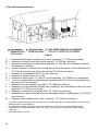
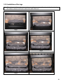
GTX-I
Natural Gas or Propane
Freestanding Direct Vent Gas Stove
Installation and Operating Instructions
WARNING: If the information in this manual is not followed exactly, a fire or explosion may result causing
property damage, personal injury, or loss of life.
For your safety
Do not store or use gasoline or other flammable vapors and liquids in the vicinity of this or any other appliance.
What to do if you smell gas
Do not try to light any appliance.
Do not touch any electrical switch; do not use any phone in your building.
Immediately call your gas supplier from a neighbor’s phone. Follow the gas supplier’s instructions.
If you cannot reach your gas supplier, call the fire department.
Installation and service must be performed by a qualified installer, service agency or the gas supplier.
Please read this manual before installing or using this appliance. Retain this manual for future reference.
45282
Table of content
1.0 INTRODUCTION .............................................................................................................. 3
1.1 Specifications ..................................................................................................................................... 3
1.2 Features ................................................................................................................................................. 5
1.3 Intended use ........................................................................................................................................ 5
1.4 General safety..................................................................................................................................... 5
2.0 OPERATION ...................................................................................................................... 6
2.1 Operation safety ................................................................................................................................ 6
2.2 Lighting instructions ...................................................................................................................... 7
2.3 Heat output adjustment................................................................................................................. 8
2.4 Fan operation ...................................................................................................................................... 8
3.0 INSTALLATION ............................................................................................................... 9
3.1 Installation and safety notes ...................................................................................................... 9
3.2 Unpacking ............................................................................................................................................. 9
3.3 Installation ............................................................................................................................................ 9
3.3.2 Gas line installation ................................................................................................................... 10
3.3.3 Thermostat or wall switch installation............................................................................ 10
3.3.4 Vent installation ........................................................................................................................... 12
4.0 MAINTENANCE ............................................................................................................ 23
4.1 Maintenance safety........................................................................................................................ 23
4.2 Recommended service ................................................................................................................ 23
4.3 Glass cleaning .................................................................................................................................. 23
4.4 Burner & pilot cleaning ............................................................................................................... 24
4.5 Fan installation ................................................................................................................................ 24
5.0 TROUBLE SHOOTING ............................................................................................. 25
6.0 REPLACEMENT PARTS ......................................................................................... 27
DROLET LIMITED LIFETIME WARRANTY ............................................................ 28
Stove Builder International Inc.
1700 Rue Léon-Harmel
Québec, PQ Canada G14 4R9
Tel. 418-527-3060
Fax : 418-527-4311
E-mail : [email protected]
2
1.0 INTRODUCTION
1.1 Specifications
TABLE 1
ITEM
INPUT: Hi
INPUT: Lo
MANIFOLD PRESSURE: Hi
MANIFOLD PRESSURE: Lo
GAS INLET SUPPLY
PRESSURE:
ORIFICE SIZE: @ 0-4500’
AIR SHUTTER OPENING
CONTROL VALVE TYPE:
VENTING
Combustion efficiency (fan off)
on maximum
Combustion efficiency (fan on)
on maximum
FAN
NATURAL GAS (NG)
32,500 Btu/hr (9.5 kW)
22,500 Btu/hr (6.6 kW)
3.5” w.c. (0.82kPa)
1.7” w.c. (0.42kPa)
Minimum: 5.0” w.c. (1.25 kPa)
Maximum: 10.5” w.c. (1.74 kPa)
2 x #57 DMS (2 x 0.043”)
*Completely open
Honeywell or SIT 820 Nova
Simpson Dura-Vent and
Security Secure Vent
PROPANE (LPG)
27,000 Btu/hr (7.9 kW)
21,000 Btu/hr (6.2 kW)
10.0” w.c. (2.49kPa)
6.3” w.c. (1.37kPa)
Minimum: 11” w.c. (2.74 kPa)
Maximum: 13” w.c. (3.24 kPa)
7/64“ (0.109”)
Completely open*
Honeywell or SIT 820
Simpson Dura-Vent and
Security Secure Vent
70.7%
68.7%
73.3%
72.3%
Variable Speed (120v / 60hz)
Variable Speed (120v / 60hz)
*May vary (±25%) depending on the installations. Judgment of installer is required.
REGISTER YOU WARRANTY ONLINE
To receive full warranty coverage, you
will need to show evidence of the date
you purchased your stove. Keep your
sales invoice. We also recommend that
you register your warranty online at
www.drolet.ca
Registering your warranty online will
help us track rapidly the information we
need on your stove.
This heating unit must serve as a supplementary heat source. An alternative heat source should be available in the home
if needed. The manufacturer cannot be responsible for additional heating costs associated with the use of an alternative
heat source.
It is highly recommended that the user buys this product from a retailer who can provide installation and maintenance
advices.
3
APPLIANCE DIMENSIONS
26 1/16"
5"
1916
11"
2016
29 1/16"
30 1/2"
Figure 1
INSTALLATION CODES
Installation must conform to local codes. In the absence of local codes, installation must conform to
the National Fuel Gas Code, ANSI Z233.1 1988, (in the U.S.), or with the current installation code
CAN/CGA B149.1 – M86 (in Canada). The heater, when installed, must be electrically grounded in
accordance with local codes or, in the absence of local codes, with the National Electric Code
ANSI/NFPA No. 70-1990 (in the U.S.) or with the current CSA C22.1 Canadian Electrical Code (in
Canada). In the state of Massachusetts, this product can only be installed by a licensed plumber or a
licensed gas fitter. Failure to comply will void the warranty.
4
1.2 Features
Ignition system:
Standing pilot ignition system with thermopile and thermocouple flame detection and piezo igniter.
Gas control:
Gas control valve type:
Automatic millivolt powered combination gas control valve with variable flame control for
convenience and on/off switch. The gas valve does not require electricity from an external
source.
Fan control:
Variable speed control:
For units equipped with a fan control, the knob controls the fan speed in connection with a heat
sensitive switch which turns on when the heater reaches operating temperature. Turning the
knob counter-clockwise turns it to the “Off” position.
Safety controls:
A safety switch will shut the system down in the event of any one of the following conditions:
Incorrectly installed vent system
Blocked vent causing flue spillage
Flow reversal or sustained down draft situation
1.3 Intended use
This appliance is intended to be used as a free standing heater. With the exception of
Massachusetts, the GTX-I may be installed in the United States and Canada in a bedroom or mobile
home provided that CR89-00 and/or ANSI A225.1/NFPA 501A standards are followed, all required
clearances are met, a wall thermostat is installed and where the maximum input is within 50 cubic
feet of room volume per 1000 BTU/hr, (i.e.1500 minimum cubic feet) and the stove must be hooked
up to a Simpson GS Dura Vent or Security Chimneys International (Secure Vent) 4” x 6 5/8” venting.
1.4 General safety
The appliance must be properly connected to a venting system in accordance with local codes. This
unit must not be connected to a chimney or flue serving any other appliance. It is equipped with a
safety control system to protect against improper venting of flue products.
WARNING: Operation of this unit when not connected to a properly installed and
maintained venting system may result in carbon monoxide poisoning.
Installation and repair should be done by a qualified service person. The appliance should be
inspected before use and at least annually by a professional service technician. Provide adequate
clearances around air openings, for combustion and ventilation air, and allow accessibility clearance
for servicing and proper operation.
5
2.0 OPERATION
2.1 Operation safety
Inspect the appliance before use. Always keep the appliance area clear and free from combustible
materials, gasoline, and other flammable vapors and liquids. Never obstruct the flow of ventilation air.
Keep the front of the appliance clear of all obstacles and foreign materials. Never obstruct or modify
the air inlet/outlet grilles of the fireplace in any manner.
CAUTION: Children and adults should be alerted to the hazards of high surface
temperature and should stay away to avoid burns or contact with hot surfaces.
Young children should be carefully supervised when they are in the same room as
the heater. Clothing or other flammable material should not be placed on or near the
unit.
Never operate the unit with the glass door off or broken since this may cause dangerous indoor air
pollution. This unit is not for use with solid fuel. Do not substitute any parts or materials. Do not
abuse the glass door by striking or slamming shut.
OUTLET
PRESSURE TAP
IGNITER
HI/LO
REGULATOR
INLET PRESSURE
TAP
GAS
CONTROL
KNOB
WIRING
TERMINALS
Figure 2
6
2.2 Lighting instructions
FOR YOUR SAFETY, READ BEFORE LIGHTING
WARNING: If you do not follow these instructions exactly, a fire or explosion may result
causing property damage, personal injury or loss of life.
A.
B.
C.
D.
This appliance has a pilot which must be lighted by hand. When lighting the pilot, follow these instructions exactly.
BEFORE LIGHTING smell all around the appliance area for gas. Be sure to smell next to the floor because some gas is heavier than air and will
settle on the floor.
WHAT TO DO IF YOU SMELL GAS
• Do not try to light any appliance.
• Do not touch any electric switch; do not use any phone in your building.
• Immediately call your gas supplier from a neighbours phone. Follow the gas supplier’s instructions.
• If you cannot reach your gas supplier, call the fire department.
Use only your hand to push in or turn the gas control knob. Never use tools. If the knob will not push in or turn by hand, don’t try to repair it, call a
qualified service technician. Force or attempted repair may result in a fire or explosion.
Do not use this appliance if any part has been under water. Immediately call a qualified service technician to inspect the appliance and to replace
any part of the control system and any gas control which has been under water.
LIGHTING INSTRUCTIONS
1.
2.
3.
4.
5.
6.
7.
8.
9.
STOP! Read the safety information above on this label.
Set the thermostat to the lowest setting.
Turn off all electric power to the appliance.
Controls are accessed by opening the bottom louver.
Push in gas control knob slightly and turn clockwise to “OFF”.
Wait five (5) minutes to clear out any gas. Then smell for gas, including near the floor. If you smell gas, STOP! Follow “B” in the safety
information above on this label. If you don’t smell gas, go to the next step.
Turn control knob counterclockwise
pilot position.
Depress control knob and push in piezo igniter button. Once pilot ignites continue to hold the control knob in for one (1) minute after the pilot is lit.
Release knob and it will pop back up. Pilot should remain lit. If it goes out, repeat steps 4 – 7.
•
If knob does not pop up when released, stop and immediately call your service technician or gas supplier.
•
If the pilot will not stay lit after several attempts, turn the gas control knob to “OFF” and call your service technician or gas supplier.
Turn gas control knob counterclockwise to “ON”. Turn on all electric power to the appliance. Set thermostat to desired setting or turn appliance
switch to “ON” position then close bottom louver.
TO TURN GAS OFF TO APPLIANCE
1.Set thermostat to lowest setting.
2.Turn off all electric power to the appliance if service is to be performed.
3.Push in gas control knob slightly and turn clockwise to “OFF”, do not force.
Note: The valve is equipped with a safety lockout, once in the “OFF” position you must wait until the thermopile has cooled before attempting
to light the pilot (approximately 3 minutes).
7
2.3 Heat output adjustment
The valve supplied with the appliance has a HI/LO knob to control the heat output and flame height
(see Figure 2).
2.4 Fan operation
The fan control knob is located on the control panel and may be adjusted to the following settings:
OFF: Turn the control fully counter-clockwise until the switch operates.
Variable Speed Setting:
Turn the control to the desired setting. When the knob is turned fully clockwise the fan will set to
minimum speed.
Do not use this appliance if any part has been under water. Immediately call a qualified service
technician to inspect the appliance and to replace any part of the control system and any gas controls
which have been under water.
Due to high temperatures, the appliance should be located out of traffic and away from furniture and
draperies.
8
3.0 INSTALLATION
3.1 Installation and safety notes
Read all instructions before starting installation and follow them carefully during installation to ensure
maximum benefit and safety. Failure to follow these instructions will void your warranty and may
present a fire hazard. See the warranty at the back of this manual for disclaimers regarding improper
installation. This free standing fireplace and its components are tested and safe when installed in
accordance with this installation manual.
ELECTRICAL GROUNDING NOTE: A three-prong (grounding) plug, for your protection against
shock hazard, is provided and should be plugged directly into a properly grounded three-prong
receptacle. Do not cut or remove the grounding prong from this plug.
WARNING: Do not connect 120 VAC to the gas control valve or it’s wiring, as this
will damage the valve.
3.2 Unpacking
Please check the appliance carefully for any damaged or missing components (specifically check the
glass condition). Report any problems to your dealer. This unit is shipped with the logs in separate
box.
3.3 Installation
For satisfactory results it is necessary to plan certain aspects of the installation prior to the
appliance’s final positioning. These include the vent system, the gas piping, and the fans wiring.
Combustible surfaces such as the hearth, mantle, and facing must also be planned for.
NOTE: All Installations Require Venting.
3.3.1 Minimum clearances to combustibles
This free standing fireplace is suitable for installation on a combustible
Minimum Clearances to Combustibles are:
From ceiling:
From sidewall:
From backwall:
From corner (corner installation)
30” (77 cm)
8” (21 cm)
5” (13 cm)
2” (5 cm)
Note: The appliance can sit directly on a combustible surface provided that it remains stable.
Verification with local codes is recommended.
9
3.3.2 Gas line installation
Install supply line using any piping approved for your installation meeting CAN/CGA 6.10, AA 3,
ANSI Z21.24 or Z21.45. A qualified gas fitter should install the gas line in accordance with all
local building codes. If codes permit, coiled copper tubing may be used for gas supply.
Pressure taps are provided on the gas control for test gauge connections to measure the manifold
and inlet pressures.
This appliance must be isolated from the gas supply piping system by closing its individual manual
shut off valve during any pressure testing of the gas supply piping system at test pressures equal
to or less than 1/2 psig (3.45 kPa).
The appliance and its individual shut off valve must be disconnected from the gas supply piping
system during any pressure testing of the system at test pressures in excess of 1/2 psig (3.45
kPa).
Install the gas line as follows:
The gas line connection found on the back of the valve is a 3/8" black iron nipple. An AGA and/or
CGA approved shut off valve can be installed in conjunction with the nipple if so desired.
Installing the shut off valve on the end of the nipple will allow quick accessibility.
Upon initial firing check manifold pressure at pressure tap located on the front of the control valve
(see Figure 2).
WARNING: Do not use an open flame to test for gas leaks.
3.3.3 Thermostat or wall switch installation
The burner control switch is located on the control panel. For your convenience, the unit can also be
operated by a thermostat, or a wall switch control. Millivolt thermostats are available from most
hearth dealers. Bedroom installations require the use of a wall thermostat.
NOTE: The thermostat or wall switch MUST be rated for millivolt use. Minimize
splicing in all millivolt wiring & solder all unavoidable splices.
3.3.3.1 Remote control installation
Please refer to instructions included with kit.
3.3.3.2 Thermostat or wall switch installation
1. Mount the thermostat or wall switch in the desired location and run "two conductor thermostat
wire" to the burner control switch (Figure 3). To bypass the burner control switch, run the wires
directly to the gas valve (Figure 4).
Purchase "two conductor thermostat wire", which is not provided, at any local supplier. The
gauge of thermostat wire will determine the maximum wire length and distance at which to locate
the thermostat or wall switch. See table 2 below and the information packaged with the
thermostat. Be aware that, as the length of wire increases, the probability of adequate operating
voltage decreases.
10
TABLE 2: THERMOSTAT WIRE INFORMATION
WIRE SIZE
MAX. WIRE LENGTH
AWG
mm
ft.
m
22
0.6
10
3.1
20
0.8
25
7.6
18
1.0
40
12.2
16
1.3
64
19.5
14
1.6
100
30.5
2. Solder an appropriate wire connector to each wire. To connect to the burner switch, 1/4" female
quick connects are required and to connect directly to the valve use spade tongue connectors.
3. Check tests can be performed on the valve by referring to the trouble shooting guide.
Figure 3
11
Figure 4
3.3.4 Vent installation
3.3.4.1 Acceptable configurations
The stove must be connected to Simpson GS Dura Vent or Security Chimneys International (Secure
Vent) 4” x 6 5/8” venting. Install the vent components according to the manufacturer's instructions.
Use a maximum of two 90 degree elbows and four 45 degree elbows. Slope horizontal pipe at least
1/4" (6 mm) rise per foot of horizontal run. Allow 2" (50 mm) clearance to the vent. A vinyl siding
standoff must be used when terminating horizontally to vinyl siding as well a heat guard must be
installed when using a 36" snorkel. Refer to the graph for allowable vent configurations.
Note: If at any time the vent-air intake piping is dismantled, use the vent manufacturer’s instructions
and the sealing instructions for reassembly.
For horizontal termination:
The maximum horizontal length using the minimum vertical length must consist of:
•
A minimum of 6 feet (1.82m) of vertical length directly on top of stove.
•
One 90 degree elbow.
•
A maximum of 10 feet (3m) of horizontal length.
•
A wall thimble.
•
A wall thimble cover.
•
A horizontal termination cap.
12
The minimum vertical length using the maximum horizontal length consists of:
•
A minimum of 24” (61cm) vertical length directly on top of the stove.
•
A maximum of one 90 degree elbow.
•
A maximum of 12” (31cm) total horizontal length.
•
A wall thimble.
•
A wall thimble cover.
•
Horizontal termination cap.
For vertical termination:
The maximum vertical system consists of:
•
Up to 30 feet (9m) of vertical length.
•
Fire stop, flashing, and collar.
•
High Wind termination cap.
Use a ceiling fire stop when penetrating a ceiling. Use a round support box/wall thimble when
penetrating an inside wall, or on an outside wall, only when additional support or decorative trim is
required. The round support box is not required on basic installations. Vent terminals shall not be
recessed into a wall or siding.
HORIZONTAL AND VERTICAL VENT CHART
Length of vertical
vent
Length of
horizontal vent
13
3.3.4.2 Typical vent installation
Vent terminals shall not be recessed into a wall or siding.
Figure 5
14
3.3.4.3 Use of sealant
Sealant is required on vent system joints. On longer vent runs, especially vertical runs, sealant will
ensure that the combustion air enters from outdoors, and not through the vent joints. Use a sealing
product, available from your local Drolet dealer, on the inner pipe joint, applying the sealant around
the outside of the male part of the vent. A bead of silicone should be used on the outside of the joint
after assembly to seal the supply air.
“WARNING: A minimum clearance to combustibles must be maintained around the vent pipe of 2” on
horizontal pipe runs and 1” on vertical pipe runs.
Apply RTV high temperature sealant around male
pipe.
Figure 6
15
3.3.4.4 Horizontal wall vent termination
The position of the horizontal vent termination must be positioned in such a way as to meet all local building
codes. Attach the correct length of vertical section pipe and an elbow fitting to the stove. Mark the center line
of the pipe facing the wall (allowing for a 1/4” rise per foot of horizontal, example 10 ft of horizontal would
require a rise of 2.5”).
NOTE: ALLOWING THE VENT PIPE TO SLOPE DOWN TOWARDS THE VENT TERMINATION COULD
CAUSE POOR COMBUSTION AND/OR HIGH TEMPERTURES THAT MAY PRESENT A FIRE HAZARD.
Mark a 10” x 10” square around the center mark (inside dimensions).Cut and frame the exterior wall to except
the wall thimble. Install the wall thimble shield using wood screws. If the wall being penetrated is constructed of
non-combustible material, a 7” hole for the vent pipe is acceptable.
Siding
Siding standoff
Wall Thimble
10” Duravent
Part #942
Screws
Apply sealant
On four sides
Caution: When installing the terminal on to
vinyl siding, a vinyl siding kit or furring strips
must be used to prevent the terminal from
being recessed into the siding.
When the termination is to be attached to vinyl
siding, apply a bead of non-hardening mastic
around the outside edge to form a seal between
the standoff and the terminal. Attach the terminal
to the exterior wall using four wood screws
through the holes in the corner of the vent
terminal. Complete the terminal installation;
apply a bead of mastic around the outer edge of
the vinyl standoff. With the termination installed
you can now connect the completed vent
assembly by sliding the unit back towards the
wall and carefully inserting the pipe into the
terminal. Before the final connection is made
slide on the decorative wall thimble. Secure the
terminal by securing the termination straps to the
pipe as close to the exterior wall as possible
using sheet metal screws, ensure that the straps
are hidden by the wall thimble cover. Apply
decorative trim if required.
Before sliding the pipe into the termination, ensure that you have slid the decorative wall thimble cover and
penetration heat shield over the pipe.
Slide the pipe into the vent, making sure that at least 11/4” overlap between the pipe and the terminal. Attach
the pipe by attaching two sheet metal screws through the terminal straps and into the pipe. Bend back the
straps towards the terminal making sure they are hidden by the decorative thimble. Finally attach the wall
penetration heat shield and secure with wood screws
16
HOT
Basement Installations
To achieve the minimum vertical rise a 36” snorkel must be used. Where the bottom of the terminal may be
blocked by snow, ensure provision is made for adequate drainage.
3.3.4.5 Vertical installation
Always maintain a 1” clearance around the vent pipe (vertical) and 2” clearance horizontal, when passing
through ceilings, walls, roofs, enclosures, attic rafter or any combustible surfaces.
DO NOT PACK AIR SPACES WITH INSULATION.
Refer to the vent charts for maximum allowable vertical and horizontal allowable installations.
When planning your installation determine if ceiling joists, roof rafters or other framing will obstruct the vent
system. You may have to use 45° elbows to navigate around any obstacles. When passing through a flat
ceiling install a Box/Wall thimble. Cut a 10” square hole and frame as shown in the diagram opposite.
Ensure all pipe sections are fully twist locked.
NOTE: ALWAYS CHECK YOUR LOCAL CODES BEFORE INSTALLING VENTING. CLEARANCES ETC, MAY VARY
FROM STATE TO STATE (PROVINCE TO PROVINCE).
NOTE: CONSULT DURAVENT PARTS LIST OR SECURITY CHIMNEY PARTS LIST FOR PART NUMBERS (USE
ONLY DURAVENT GS SYSTEM OR SECURITY DV PARTS).
17
Through Roof Framing
Maintain 10” opening relative to the pitch of the roof.
Use a suitable round or square support through the roof. Ensure adequate heat shield protection is provided.
Termination above Roof
Consult local codes for minimum vent cap height above the roof .
To prevent water seepage; install the flashing with upper portion slid under the roofing material and the lower
portion over the roofing material.
Note: do not fasten down until the final adjustments to the vent have been made.
18
3.3.4.6 Vent terminal locations
Figure 7
A = clearances above grade, veranda, porch, deck, or balcony [* 12" (305 mm) minimum]
B = clearance to window or door that may be opened [* 12" (305 mm) minimum]
C = clearance to permanently closed window [minimum 12" (305 mm) recommended to prevent
condensation on window]
D = vertical clearance to ventilated soffit located above the terminal within a horizontal distance of
24" (610 mm) from the centre-line of the terminal 23" (584 mm) minimum
E = clearance to unventilated soffit 23" (584 mm) minimum
F = clearance to outside corner = 0" (0 mm)
G = clearance to inside corner = 0" (0mm) to non-combustibles, or 8" (203mm) to combustibles
H = * not to be installed above a meter/regulator assembly within 36" (914 mm) horizontally from
the centre-line of the regulator
I = clearance to service regulator vent outlet [* 72" (1829 mm) minimum]
J = clearance to non-mechanical air supply inlet to building or the combustion air inlet to any other
appliance [* 12" (305 mm) minimum]
K = clearance to a mechanical air supply inlet [* 72" (1829 mm) minimum]
L = clearance above paved side-walk or a paved driveway located on public property [* 84" (2134
mm) minimum]
M = clearance under veranda, porch, deck, or balcony [* 12" (305 mm) minimum ]
*
*
19
a vent shall not terminate directly above a side-walk or paved driveway which is located between two single family
dwellings and serves both dwellings*
only permitted if veranda, porch, deck, or balcony is fully open on a minimum of 2 sides beneath the floor*
as specified in CGA B149 Installation Code (1991) NOTE: local codes or regulations may specify different
clearances
follow ANSI Z223.1 for U.S.A.
3.3.5 Installation of the logs
Note: If the pictures in this section are not clear enough, you may see them in color by downloading
this owner’s manual via Drolet’s web site at www.drolet.ca
Step 1
Step 2
Step 3
Step 4
Step 6
Step 7
20
3.3.6 Initial firing
At the time of the first burn, the appliance may emit an odor, accompanied by smoke. This is perfectly
normal. As the metal heats to the critical point (about 375 degrees F), part of the paint components
turns to light gray smoke as the dormant silicone resin activates and begins to bond with the metal.
After the “burn-off” is complete, there will be no more smoke or odor. Although the smoke/odor is not
toxic, it is annoying and it displaces oxygen. After the fireplace has been burned about three times
(for at least one hour), the entire surface will have cured. If the process is not complete, it will
continue to give off some odor. It is important to ventilate the house during these initial burns. We
advise removing young children, elderly persons and anyone suffering from breathing disorders (or
are sensitive to oxygen imbalances) from the area while this process is occurring.
NOTE: It is normal for the appliance to expand and contract while it heats up or cools down whether
this is from a cold start or a steady-state condition where the fan has come on or off. Under
these circumstances it is possible that the expansion/contraction of the metal parts may
produce a ticking sound. Occasionally, after a cold start, vapor may condense and fog the
glass, and the flames may be partially blue. After a few minutes the moisture will disappear
and the flames will become yellow.
3.3.6.1 Manifold pressure regulator adjustment
The manifold pressure regulator controls gas input and flame height, and is pre-adjusted at the
factory. No further adjustment is required. Manifold pressure can be verified only (see Figure 2).
3.3.6.2 Pilot adjustment
For proper operation, the pilot and main burner flames must be steady and not lifting off or floating.
The top 3/8” – 1/2” (10-13mm) of the thermopile should be engulfed by the pilot flame. The pilot
flame adjustment should be performed by a qualified service person only. To adjust the pilot flame,
turn the pilot adjustment screw counter-clockwise to increase and clockwise to decrease the flame.
Ensure that the pilot flame completely engulfs the thermopile (see figure 8).
Igniter
Thermocouple
Thermopile
Burner
Figure 8
21
3.3.7 Altitude adjustment
All valves have been pre-set and certified for installation at elevations from 0 – 4500 feet (1 – 1372m)
above sea level.
When installing this heater at higher elevations, it is necessary to decrease the input rating by
replacing the existing burner orifice with a smaller size for installations over 4500 feet (1372m). The
appliances input should be reduced 4% for each additional 1000 feet (305m) above sea level. For
the USA, de-rate the heater from sea level according to the gas installation code.
22
4.0 MAINTENANCE
4.1 Maintenance safety
Turn off the gas to the main burner and allow the heater to cool for up to 30 minutes before
servicing.
Service and repair should be done by a qualified service person. The appliance should be inspected
before use and at least annually by a professional service technician. More frequent cleaning may be
required due to excessive lint from carpeting, bedding material, etc. It is important that the access
door compartment, burner, and circulating air passageways be kept clean to provide for adequate
combustion and ventilation airflow. Do not substitute materials or use components other than factory
supplied.
4.2 Recommended service
1. Examine the venting system periodically.
2. Visually check the burner and pilot flames occasionally.
Visually inspect height and color of
flames.
3. Clean the glass as needed.
4. Have the appliance inspected annually by a professional service technician.
5. Clean the appliance regularly.
NOTE: Safety screens removed for service must be replaced prior to operating the heater.
Annual service: An annual service call should take between 1 – 2 hours. Start by disassembling the
unit; take off the glass and remove all the logs, embers, burner, and fan. A small toothbrush is a
handy tool for cleaning the fan. Loosen all the debris on the fan blades and vacuum it off. Vacuum
the whole firebox and all the air passages. Clean the burner, pilot orifice, main orifice, logs, etc. After
everything is clean, check all the connections and the chassis ground and reassemble. Fire up the
unit and check the electrical readings of the thermopile/thermocouple. Clean the glass. Check the
gas pressure. Check the draft (the venting system should also be checked).
4.3 Glass cleaning
The inside of the glass may require periodic cleaning to remove deposits left from impurities in the
gas and combustion air. For best results, use a gas fireplace glass cleaner. A suitable cleaner is
available from your dealer. Avoid the use of ammonia based cleaners such as Windex®. Do not
clean while hot. Do not use abrasive cleaners. Make sure you clean off the white film on the
fireplace glass as soon as possible – otherwise the glass may deteriorate.
23
4.4 Burner & pilot cleaning
Periodic cleaning is necessary for proper operation. Remove the burner, and check that the burner
orifice is clean. Visually inspect the pilot. Brush or blow away any dust, lint, or foreign debris. If the
pilot orifice is plugged, disassembly may be required to remove any foreign material from the orifice
or tubing.
4.5 Fan installation
Caution: Label all wires prior to disconnection when servicing controls. Wiring errors can cause
improper and dangerous operation. Verify proper operation after servicing.
24
5.0 TROUBLE SHOOTING
SYMPTOM
POSSIBLE CAUSE
I.
A. No spark at electrode (weak or not heat source for pilot ignition)
Pilot will not light after
repeated triggering of the
piezo ignition button
1. Improper ignition
2. Poor connections at igniter
and ignition electrode
3. Broken ceramic cover on
ignition electrode
4. Defective piezo igniter
B. No gas or low gas pressure
1. Gas line shut off(s) may not be
turned on
2. No gas supply (LPG)
II. Pilot will not stay lit after
following the lighting
instructions
3. Air in gas lines
4. Gas lines may not be
connected
5. Low pressure may be caused
by bent line
6. Valve control knob not fully
depressed in “PILOT” position
A. Thermocouple / Valve
1. Weak or improperly located
pilot flame
2. Defective thermocouple
3. Thermocouple not installed
properly
4.
25
Open wire connection in pilot
circuit
CORRECTIVE ACTION
1. Align the electrode with 1/8” (3mm) gap
to pilot hood
2. Reconnect if loose
3. Replace pilot assembly
4. Replace piezo igniter
1. Turn of shut-off valves
2. Check propane tank; you may be out of
fuel
3. Purge gas lines
4. Connect all gas lines
5. Check for a kinked line
6. Fully depress control knob
1. Adjust and clean pilot. The flame must
impinge on or engulf the thermocouple.
2. Have the thermostat contacts open and
pilot lit with the knob turned to the "Pilot"
position. Reading should be a minimum
of 18 mV for a new thermocouple, if the
reading is less than 18mV replace the
thermocouple.
3. Make sure all wire connections at the gas
valve terminals are tight and the
thermocouple is fully inserted into the
mounting bracket
4. Check wire continuity and connections in
the pilot circuit
III. Main burner will not light
A. Valve / Switches
1. Valve control off
2. Blockage at the burner (line,
orifice, or ports)
3. Defective wall switch or
thermostat
4. Defective wiring or connections
5. Excessive length of thermostat
wire from valve to wall switch or
thermostat
6. Wall switch or thermostat
incorrectly wired
7. Defective Valve
8. Thermopile may not be
generating sufficient voltage
(460 mV)
9. Wall switch, thermostat, or wires
are defective
IV. Soot deposits on glass
V. Flame burns blue and lifts
off burner
3. Conduct a continuity test or jumper wire
test and replace if defective
4. Conduct a test with a jumper wire and
repair as required
5. Reduce wire length to less than 100 feet or
increase wire size
6. Wire correctly
7. Turn valve and “ON/OFF” switch to the
“ON” position. Check with millivolt meter
at terminals TP-TH & TH. Millivolt meter
should read greater then 460 millivolts. If
the reading is OK and the burner does not
come on, replace the gas valve
8. Recheck using the millivolt meter. The
pilot flame may not be high enough for the
flame to properly engulf the thermopile. If
so, adjust and reset. If voltage is still
insufficient, replace thermopile
9. Follow previous corrective action, check
switch and wiring. Replace where
defective
1. Flame impingement on logs
1. Adjust the log set to avoid direct flame
impingement. Follow log placement
instructions
2. Improper primary air setting
3. Foreign material impeding
burner
2. Open aeration shutter more.
3. Ensure that no foreign material blocks
burner flame ports
4. Air inlet blocked or restricted
4. Clean air inlets
5. Vent system is restricted or
inadequate
5. Check correct termination is used.
1. Insufficient combustion air being
supplied
2. Manifold pressure set too high
1.Ensure that no foreign material blocks air
inlets and that the burner shutter is
correctly adjusted. Ensure the vent is
adequate
2. Check manifold pressure
3. Check vent system
1. Correct flue as required
3. Vent system restricted
VI. Flames impinge on firebox
top
1. Turn to “ON” position
2. Check and clean
1. Vent system is restricted or
inadequate
2. Manifold pressure too high
2. Check manifold pressure as required
26
6.0 REPLACEMENT PARTS
When requesting service or replacement parts, refer to your dealer. The following information’s will
be asked for; the model name GTX-I, the type of gas used, serial number and proof of purchase. The
damaged parts must be replaced by Drolet genuine parts. You can consult the spare parts list on our
website at www.drolet.ca or contact your Drolet dealer.
27
DROLET LIMITED LIFETIME WARRANTY
The warranty of the manufacturer extends only to the original consumer purchaser and is not transferable. This warranty
covers brand new products only, which have not been altered, modified nor repaired since shipment from factory. Proof of
purchase (dated bill of sale), model name and serial number must be supplied when making any warranty claim to your
DROLET dealer.
This warranty applies to normal residential use only. Damages caused by misuse, abuse, improper installation, lack of
maintenance, negligence or accident during transportation are not covered by this warranty.
This warranty does not cover any scratch, corrosion, warping, or discoloration caused by over firing, abrasives or
chemical cleaners. Any defect or damage caused by the use of unauthorized parts or others than original parts void this
warranty. An authorized qualified technician must perform the installation in accordance with the instructions supplied with
this product and all local and national building codes. Any service call related to an improper installation is not covered by
this warranty.
The manufacturer may require that defective products be returned or that digital pictures be provided to support the claim.
Returned products are to be shipped prepaid to the manufacturer for investigation. If a product is found to be defective,
the manufacturer will repair or replace such defect and reasonable transportation fees will be refunded. Repair work
covered by the warranty, executed at the purchaser’s domicile by an authorized qualified technician requires the prior
approval of the manufacturer. Labour cost and repair work to the account of the manufacturer are based on
predetermined rate schedule and must not exceed the wholesale price of the replacement part. All labour and freight
costs covered by this warranty are limited according to the table below.
The manufacturer at its discretion may decide to repair or replace any part or unit after inspection and investigation of the
defect. The manufacturer may, at its discretion, fully discharge all obligations with respect to this warranty by refunding
the wholesale price of any warranted but defective parts The manufacturer shall in no event be responsible for any
special, indirect, consequential damages of any nature, which are in excess of the original purchase price of the product.
DESCRIPTION
Combustion chamber (welds only), heat exchanger, and castings.
Plating (defective manufacture) – subject to limitations above
Burner
Stainless steel baffle and parts
Carbon steel baffle and parts
Ceramic logs, masonry-like panels, and ceramic glass (thermal
breakage only*)
Gas valve, pilot assembly & related parts, blowers, switches,
rheostat, and other controls.
Paint (peeling) and gaskets
*Pictures required
WARRANTY APPLICATION
PARTS
LABOUR
Lifetime
5 years
Lifetime
n/a
5 years
3 years
5 years
3 years
2 years
1 year
2 years
n/a
1 year
1 year
1 year
n/a
Shall your unit or a components be defective, contact immediately your DROLET dealer. Prior to your call make sure you
have the following information necessary to your warranty claim treatment:
•
•
Your name, address and telephone
number;
Bill of sale and dealer’s name;
•
•
Serial number and model name as indicated on the
nameplate fixed to the back of your unit;
Nature of the defect and any relevant information.
Before shipping your unit or defective component to our plant, you must obtain from your DROLET dealer an
Authorization Number. Any merchandise shipped to our plant without authorization will be refused automatically and
returned to sender.
28