1
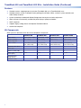
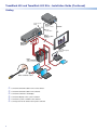
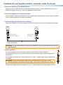
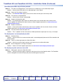
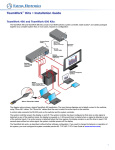
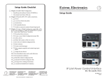
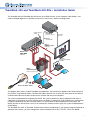
TeamWork 400 and TeamWork 600 Kits • Installation Guide
The TeamWork 400 and TeamWork 600 kits consist of an HDMI switcher, system controller, Cable Cubby®, and
cables packaged together as a complete system that, in most cases, requires no configuration.
US
®
17TT
ED
LIST IDEO
IO/V US
AUD RAT
APA
M
CO
N
LA
+5V
TX
RX
IR
UT
INP
z
/60H
50
G
S
0V
0-12
IN
10
AX
AM
UT
12
TP
WER
OU
PO
Contact Closure
& Tally
Extron
IPL T PC1
AX
AM
12
Flat Panel
AC Cord
System Controller
RS-232
Control Cable
TE
MO
RE
UT
YO
LL
TA
UT
TP
OU
1
1
4
3
T
AC
NT
2
TO
G
CO
2
-232
4
AU
RS
Tx
3
Rx
G
Extron
HDMI Pro Cable
4
TS
3
PU
IN
HDMI Video
2
I
DM
4H
al
ion
g
Re
ST
1
0
SW
15
WER
POV
12 MAX
0.3A
0
12
ST
EA
TH
lesSOU
Sa
H
RT
NO
WE
90
Extron
SW4 HDMI
60
30
0
Switcher
24
0V
/ 5A
M
AX
Flat Panel
Display w/ Integrated
Speakers
A
5
A
M
X
10
0-
24
0V
/ 5A
M
AX
/V
04
200
1
10
0-
H
al
ion
es SOUT
Sal
Reg
ST
T
0
EA
H
RT
NO
WES
15
0
12
90
60
30
0
Extron
Cable Cubby 800
Cable Access Enclosure
H
S
R
A
E
n
ro
xt
E
Extron “Show Me” Cables
The diagram above shows a typical TeamWork 400 application. The input devices (laptops and a tablet) connect to
the switcher, using Show Me cables. The Show Me cables allow the user to select the active input on the switcher.
A control cable connects the RS-232 ports on the switcher and the system controller.
The system controller powers the display on and off. The system controller has been configured so that when a
video signal is detected on any of the switcher inputs, the display is powered on. A 30 second timer is started when
no signal is detected on any of the switcher inputs. If an active source is detected before the timer expires, the
display remains on and the timer is reset. If 30 seconds pass without an active signal, the system controller powers
off the display.
The TeamWork kits work, as described, without further software configuration. If you need to change the behavior or
operation of the system, you must configure the system controller (see the IPL T PC1/IPL T PC1i User Guide).
1
TeamWork 400 and TeamWork 600 Kits • Installation Guide (Continued)
Features
zz
Standard systems support groups of up to four (TeamWork 400) or six (TeamWork 600) users.
zz
Standard systems contain a complete turnkey package that includes cables, switcher, system controller, and
Cable Cubby enclosure.
zz
System controller pre-loaded with Global Configurator that requires no further adjustment.
zz
Works with most commercially available flat panel displays, laptops and tablets.
zz
HDCP compliant
zz
Supports legacy analog sources with optional TeamWork VGA kit.
zz
Section 508 compliant.
Kit Components
When your kit is delivered, check that all the components are present.
TeamWork 400
TeamWork 400i
HDMI switcher
1 (SW4 HDMI, 4 input)
1 (SW4 HDMI, 4 input) 1 (SW6 HDMI, 6 input)
1 (SW6 HDMI, 6 input)
System controller
1 (IPL T PC1)
1 (IPL T PC1i)
1 (IPL T PC1i)
1 (IPL T PC1)
TeamWork 600i
Cable Cubby 800
1
1
1
1
Power modules
2 US modules included
(4 AC outlets total)
Sold separately
(2 AC outlets total)
2 US modules included
(4 AC outlets total)
Sold separately
(2 AC outlets total)
HDMI Show Me cables
4
4
6
6
HDMI cable
1
1
1
1
Switcher control cable
1
1
1
1
Cable Cubby AAP brackets
(three-space)
2 pairs
3 pairs
2 pairs
3 pairs
Blank AAP plates
(single-space)
2
2
2
2
Installation Guide
2
TeamWork 600
TeamWork 400, 400i, 600, and 600i Kits Installation Guide
Display Requirements
The TeamWork system is designed to work with most brands and models of flat panel displays available worldwide.
For optimum performance, consider the following when selecting the displays for your TeamWork installation. The
display should be tested thoroughly prior to installation or mass deployment of TeamWork systems.
Power attributes — The system works by controlling AC power to the display. When the display is in the ON
state with an HDMI input selected, it must be able to power back ON to the same HDMI input when AC power
is disconnected and reconnected. If the display doesn’t behave this way, an alternate display should be used.
Alternatively, you may need to control the display a different way (i.e. RS-232, infrared, or via Ethernet) using a
different type of Extron control processor.
Sleep mode — if the display has a Sleep Mode feature (sometimes called ‘auto sleep’), it must be disabled. Many
displays have an option to disable this within the menu settings.
Resolution – The TeamWork systems were designed for use with flat panels having an HDMI input connector and
having a native resolution of 1080p. Many of the readily available consumer and professional displays support 1080p
natively.
Audio – Audio from source devices is supported in the TeamWork system by routing it as an embedded audio signal
to the display for playback via integrated speakers. Most displays with HDMI inputs and integrated speakers work
this way. Some professional or commercial grade displays do not have integrated speakers and will not support
audio playback. Typically, source devices with HDMI output connectors embed audio onto the HDMI connector.
NOTES:
• Always check and test compatibility before installation. Some systems may require advanced configuration of
the system controller and require the display to be controlled by RS-232, Ethernet, or Infrared.
• Some displays support a lockout of local buttons. Extron recommends that, after setup, user accessible
controls are locked whenever possible. This ensures the display remains optimized for the TeamWork system.
TeamWork systems require a display that
returns to the previous state when the
power cord is disconnected and then
plugged back in.
Teamwork Systems work
by controlling AC power
to the display.
How to check if a display is compatible:
Extron
System
Controller
®
100-120VAC 50/60Hz
POWER OUTPUT 12A MAX
Tx Rx
+5V
INPUT
IR
IN
US
LISTED 17TT
AUDIO/VIDEO
APARATUS
COM
S G
RS-232
Switcher Control
INPUTS
OUTPUT
REMOTE
TALLYOUT
POWER
12V
0.3A MAX
1
2
3
4
1
2
3
2
3
4 G
2.
Turn the display ON.
3.
Select the HDMI input.
4.
Adjust the volume.
5.
Unplug the display (remove AC power).
6.
Re-apply AC power to the display.
If the display powers back up (to the ON state)
and to the same input and volume level, the
display will work with the TeamWork system.
4 G
CONTACT
1
Apply AC power to the display.
LAN
12A MAX
Extron
HDMI Switcher
1.
RS-232 AUTO
Tx Rx
AC Power
For Audio Playback
display should have
integrated speakers.
Display should have an HDMI
input and support embedded
audio.
1080p Native
Resolution Display
3
TeamWork 400 and TeamWork 600 Kits • Installation Guide (Continued)
Installation
Install the Power Modules in the Cable Cubby
Detailed instructions are in the Cable Cubby Setup
Guide.
Power Module
Extron recommends the layout shown to the right
with AAP shelf assemblies on either side of the power
modules.
UNSWITCHED
125 50/60HZ
5A EACH
AAP Shelf Assembly with
Cable Pass-through
UNSWITCHED
125 50/60HZ
5A EACH
Blank AAP
NOTE: Depending on your country, a power
module may occupy two or three AAP spaces,
so your final configuration may look slightly
different.
Secure the power modules in position with the provided
#4-40 Phillips head screws and star washers.
WARNING:Possible electric shock: To ensure
good electric grounding, you must use the star
washers with the screws.
Install the AAP Shelf Assembly and Show Me Cables
OUTPUT
(to switcher)
INPUT
(to source device)
Top of Cable Cubby
Share Button
Bottom of
Cable Cubby
Three-conductor
pigtail for contact
closure and tally
ATTENTION:
• The end with the button and LED
connects to the input devices and must
come out of the top of the Cable Cubby.
“Show Me” Cable
• The end with the three-conductor pigtail
connects to the switcher and must come
out of the bottom of the Cable Cubby.
1.
Assemble the AAP shelf assembly.
2.
Insert the AAP assemblies into the Cable
Cubby from underneath and secure them
in position with the provided #4‑40 Phillips
head screws and star washers.
“Show Me” Cables must
be inserted into shelf
Assemblies as it is
being constructed.
a
Split Grommet
Plug
AAP Shelf
Assemblies
Shelf
Brackets
4
b
Mounting and Placement of System Components
Decide where you will install your TeamWork system and where the individual components will be placed.
zz
The Cable Cubby should provide easy access for as many users as possible. Ensure that there is ample space
for cables under the table. Ensure that the edge on which the lid opens is correctly oriented.
zz
The system controller should be placed close to the display.
zz
The SW4 HDMI (or SW6 HDMI) switcher should be placed close to the Cable Cubby.
1080p Native
Resolution Display
VGA “Show Me”
Cable
HDMI”Show Me”
Cable
Switcher
INPUTS
INPUTS
AUTO
SWITCH
IR
1
2
3
OUTPUT
SIGNAL
4
1
2
3
HDMI Video to Display
4
HDCP
CONFIG
SW4 HDMI
HDMI SWITCHER
VGA Kit
(optional)
Extron
Cable Cubby
Power
Supplies (2)
ADJUST
CONFIG
MENU
IPL T PC1
R
ENTER
RGB - HDMI 300 A
AC Power To Display
POWER
100
TX
INPUT
RX
IR
LINK
ACT
System Controller
Shown mounted with
optional Extron UTS 100/UTS 150
Under Table Shelf System.
Cable Access Enclosure
Secure “Show Me” Cable
to Cable Cubby and create a
loop.
Installing the Cable Cubby in the Table
Before cutting the table and installing the Cable Cubby, see the Cable Cubby Setup Guide (see www.extron.com).
ATTENTION:
• Ensure that the orientation of the cable cubby and the hole dimensions are correct before cutting the table.
• After installation, secure the cables to avoid them becoming tangled (see the figure above).
5
TeamWork 400 and TeamWork 600 Kits • Installation Guide (Continued)
Cabling
US
®
CO
17TT
ED
LIST IDEO
IO/V
AUD ATUS
APAR
M
N
LA
+5V
TX
RX
IR
UT
INP
Hz
/60
50
V
G
S
20
0-1
IN
10
X
A MA
UT
12
TP
R OU
WE
PO
Contact Closure
& Tally
Extron
IPL T PC1
UT
UT
1
1
4
3
T
AC
NT
2
G
CO
2
4
-232
AU
RS
Tx
3
Rx
G
Extron
HDMI Pro Cable
4
TS
3
PU
IN
I
DM
Re
ST
1
0
15
SW
c
WER
POV
12 MAX
0.3A
Extron
f
SW4 HDMI
Switcher
0
ST
s UTH
ale SO
lS
na
gio
HDMI Video
2
4H
d
TO
TA
TP
OU
Flat Panel
AC Cord
RS-232
Control Cable
TE
MO
RE
X
A MA
System Controller
e
YO
LL
f
12
EA
H
RT
NO
WE
12
90
60
b
30
0
24
0V
/ 5A
MA
X
Flat Panel
Display w/ Integrated
Speakers
H
010
1
00
04
2-
X
MA
5
/V
/ 5A
M
A
0V
X
A
24
010
ST
T
WES
0
12
90
60
30
0
Extron
Cable Cubby 800
Cable Access Enclosure
a
E
R
A
H
S
n
ro
xt
E
Extron “Show Me” Cables
a
b
c
d
e
f
6
Connect the Show Me cables to the source devices.
Connect the Show Me cables to the switcher.
Connect the switcher to the display.
Connect the display to the system controller.
Connect the system controller to the switcher.
Connect power to the switcher and system controller.
ales SO
UT
lS
iona
Reg
0
15
EA
H
RT
NO
Show Me Cables
The Extron “Show Me” cables are for use with Extron TeamWork systems. They feature a Share button for remote
input source selection and a control pigtail, which may be wired directly into Extron switchers with contact closure
and tally outputs.
OUTPUT
(to switcher)
INPUT
(to source device)
Top of Cable Cubby
Bottom of
Cable Cubby
Three-conductor
pigtail for contact
closure and tally
Share Button
1.
Connect the input end of the Show Me cable to the source device.
2.
Connect the HDMI output to the Extron switcher.
Extron SW4 HDMI Switcher (HDMI input)
SW4 HDMI
INPUTS
1
2
3
OUTPUT
REMOTE
TALLY OUT
4
POWER
12V
0.4A MAX
1
2
3
REMOTE
4 +v
CONTACT
RS-232 AUTO
TALLY OUT
1
2
3
4 G
Tx Rx
1
SHOW ME CABLE
SWITCHER END
(output)
2
3
4
+v
CONTACT
Male HDMI connector
1
2
3
4 G
RS-232 AUTO
Tx Rx
Yellow
Three-conductor
pigtail for contact
closure and tally
Drain wire
(not used)
Green
Pigtail
3.
Connect the Green (Tally Out) and Yellow (Contact) pigtail wires as shown above. The number under the Tally Out
and Contact pins must correspond to the video input on the switcher.
NOTES:
• The drain wire does not need to be wired to the switcher. The “Show Me” cables are grounded via the
video connectors.
• Do not connect the “Show Me” cable to the +V pin on the Extron switcher.
Press the Share button to switch the connected source to the main presentation display.
Pressing the Share button creates a momentary contact closure, which triggers the switcher to select the
connected source device. If a tally output is available, the button will light up blue.
NOTES:
• The source device provides the +5 VDC supply voltage needed to illuminate the Share button. If the
source device does not supply this +5VDC, the Share button will not illuminate. Many mobile devices do
not provide the required voltage to light up the button.
• Digital “Show Me” cables support embedded audio and CEC signals.
7
TeamWork 400 and TeamWork 600 Kits • Installation Guide (Continued)
Connect the Switcher to the Display Device
Connect the switcher HDMI output to the HDMI input of the display device, using the provided cable. Do not use
HDMI to DVI adapters. If necessary, see the user guide for the display device.
Connect the Display to the System Controller
Connect the power cord from the display device to the power output receptacle of the system controller. TeamWork
systems work by controlling the AC power to the display.
Connect the System Controller to the Switcher
Connect the COM port of the system controller to the RS-232 port on the switcher with the provided control cable.
System
Controller
Switcher
(IPL T PC1)
(SW4 HDMI)
COM
TX RX
RS-232 AUTO
+5V
Tx Rx
4 pole connector
(to system controller)
5 pole connector
(to switcher)
Switcher Control Cable
ATTENTION:The two ends of the RS-232 control cable are different. One has a 4 pole connector, the other has a
5 pole connector.
Connecting Power
The system controller uses an internal power supply. Connect the power cord to a wall outlet.
The TeamWork 600 systems use a 6 input switcher with an internal power supply. Connect the power cord
to a wall outlet.
The TeamWork 400 systems use a 4 input switcher with a 12 VDC, 1 A power supply, which is provided with
the switcher.
ATTENTION:Do not connect the power supply to the SW4 HDMI switcher until you have read the
Attention notifications in the “Wiring the Power Supply” section of the SW HDMI Series User Guide.
The optional TeamWork VGA kit also includes a 12 VDC, 1 A power supply for the analog to digital converter.
8
POWER
12V
0.4A MAX
Testing the System
The TeamWork system has been pre-configured so that, once all the connections have been made and the devices
are all powered on, there should be no need of further configuration for the system to work. To ensure that the
system has been set up correctly, follow these steps:
1.
Power on the equipment
zz
Source devices
zz
Switcher (IPL T PC1)
zz
System controller
2.
Press the power button (a) on the front panel of the system
controller. The LED (b) lights green when power is being supplied
to the attached output device.
3.
Turn on the display and confirm that the display is receiving
power.
1
IPL T PC1
POWER
100
R
TX
INPUT
RX
IR
LINK
4.
Go to the menu for the display and disable the Sleep Mode
feature. If necessary, see the display user guide.
5.
Press the power button on the power controller. The LED should
go out and the display should be turned off.
6.
Connect one of the Show Me cables to a video source, such as a laptop.
7.
Press the Show Me button on that cable. If the source device is providing a video signal, the LED on the
Show Me cable lights blue and the display automatically turns on.
8.
Connect a second Show Me cable to a second video source.
9.
Repeat step 7 to verify that the second source device is providing a video signal and it is the output signal from
the switcher.
ACT
2
When the button on the second Show Me cable is pressed, the LED lights blue and the LED on the first cable is
switched off.
10.
Disconnect all the Show Me cables from the source devices.
After about 30 seconds without an input signal, the display should turn off.
11.
Connect a Show Me cable to a source device and press the Show Me button on that cable.
As soon as an active video signal is detected, the display should be turned on.
Troubleshooting
No image on the display:
Cause 1 — There is a problem with the source device:
Solution — Verify the source device is powered on and outputs an active signal.
Cause 2 — Cable connections are incorrect:
Solution — Verify the HDMI output cable from the switcher is connected to the current HDMI input of the display.
Cause 3 — Display is off:
Solution 1 — Verify the display is in the on state.
Solution 2 — The TeamWork system turns the display on and off by controlling the AC power. If the display has a
Sleep Mode feature, this feature must be disabled to prevent the display from accidentally powering off.
Cause 4 — The display has a problem:
Solution — Verify that the display functions correctly.
Cause 5 — The display cannot show video at the incoming resolution:
Solution — The EDID settings on the switcher may need to be changed. Contact an Extron Support
representative at www.extron.com/company/contactus.aspx.
9
TeamWork 400 and TeamWork 600 Kits • Installation Guide (Continued)
Show Me button LEDs stay off when pressed:
Cause 1 — The cable is not plugged into a source device that is producing an active video output signal:
Solution — Verify that the source device is on and producing an active signal.
Cause 2 — Contact or Tally wiring is incorrect:
Solution — See Show Me Cables (page 7) to ensure the contact and tally pins are correctly wired.
Cause 3 — The switcher is not powered on:
Solution — Verify that the switcher is powered on.
Cause 4 — Problem with Show Me cable:
Solution — Try connecting the video source to a different cable. If the second cable works correctly, there
may be a problem with the Show Me cable. Contact an Extron Support representative at www.extron.com/
company/contactus.aspx.
Cause 5 — Problem with Switcher:
Solution — If none of the cables work correctly, there may be a problem with the switcher. Contact an Extron
Support representative at www.extron.com/company/contactus.aspx.
Cause 6 — The source device does not output +5V:
Solution — This is a problem with the source device. HDMI specifications require pin 18 to carry a +5V output.
The display does not automatically turn ON:
Cause 1 — Incorrect wiring:
Solution — Verify that the RS-232 communication cable is connected properly between the IPLink controller and
Extron switcher.
Cause 2 — There is no video signal present at Show Me cables:
Solution — Verify that an active signal is present at the input of any of the Show Me cables.
Cause 3 — IPLink configuration is missing or corrupted:
Solution — Contact an Extron Support representative at www.extron.com/company/contactus.aspx.
The display stays On and never turns Off:
Cause 1 — Video signal is present at Show Me cables:
Solution — Verify that no active signals are present at the inputs of any of the Show Me cables. The TeamWork
system is designed to turn off the Display only when no video signals are present.
Extron Headquarters
+1.800.633.9876 (Inside USA/Canada Only)
Extron USA - West
Extron USA - East
+1.714.491.1500+1.919.850.1000
+1.714.491.1517 FAX
+1.919.850.1001 FAX
10
Extron Europe
+800.3987.6673
(Inside Europe Only)
+31.33.453.4040
+31.33.453.4050 FAX
Extron Asia
+65.6383.4400
+65.6383.4664 FAX
Extron Japan
+81.3.3511.7655
+81.3.3511.7656 FAX
Extron China
+86.21.3760.1568
+86.21.3760.1566 FAX
Extron Middle East
+971.4.299.1800
+971.4.299.1880 FAX
© 2013 Extron Electronics All rights reserved. www.extron.com
Extron Korea
+82.2.3444.1571
+82.2.3444.1575 FAX
Extron India
1800.3070.3777
Inside India Only
+91.80.3055.3777
+91.80.3055.3737 FAX
68-2400-50 Rev. A
03 13