1
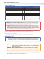
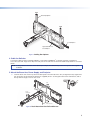
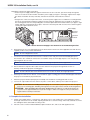
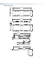
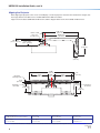
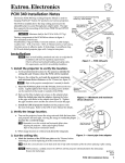
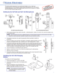
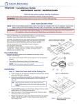
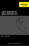
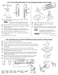
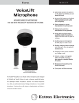
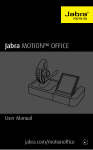
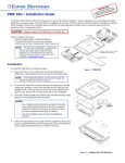
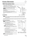
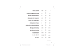
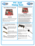
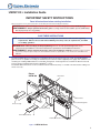
USFM 100 • Installation Guide
IMPORTANT SAFETY INSTRUCTIONS
Read all instructions before starting installation.
When using this accessory, basic precautions should always be followed, including the following:
WARNING: Risk of Personal Injury. Maximum setup load for the USFM 100 (projector arm) is 20 lbs (9.1 kg).
AVERTISSEMENT : Risque potentiel de blessure grave. La charge maximum d'installation pour le USFM 100 (le
bras du projecteur) est 9,1 kg (20 lbs).
SAVE THESE INSTRUCTIONS
NOTE: Refer to local building standards and codes to verify that the installation will meet the regulatory
requirements. Observe all local and national building and safety codes, UL requirements, and ADA
accessibility guidelines.
WARNING: Risk of Personal Injury and Property Damage. Do not exceed specified weight limits of any
component of the installation. Follow the manufacturer's specifications and installation instructions.
AVERTISSEMENT : Risque potentiel de blessure grave ou de dommages matériels. Ne dépassez pas les limites
de poids de n'importe quel composant de l'installation. Suivez les spécifications et les instructions d'installation du
fabricant.
The Extron USFM 100 is a mounting kit for suspending ultra short throw projectors from a wall. The USFM 100 base
plate enclosure is capable of mounting a PoleVault® System switcher and its supplied power supply, with sufficient room
remaining for installing additional devices and cable management. It is designed to be used with the UPB 25 universal
projector bracket (supplied with the Extron WallVault® system).
The USFM 100 has knockouts on all four sides that allow external raceways or conduits to be attached for cabling runs
where necessary.
Extron
USFM 100
Boom Arm
Base Plate
Device Mounting Plate
Arm Cover (top)
Arm Cover (front)
Arm Cover (buttom)
Plastic Enclosure Cover
Figure 1. USFM
100 Parts
1
USFM 100 Installation Guide, cont'd
Hardware Included in the Kit
Parts
Qty
¼ - 20 x 2 inch, pan head bolts
¼ inch toggle assembly
¼ inch metal washers (47/64 inch O.D.)
5/16 x 3 inch lag screws
5/16 inch metal washers (11/32 inch I.D., 11/16 inch O.D.)
¼-28 x 3/4 inch screw
¼-20 x 1/2 inch button screws
10-32 x 3/8 inch pan head screws
10-32 x ¼ inch set screw
6-32 x ¼ inch button screws
4
4
8
4
4
1
4
2
1
12
6-32 x ½ inch button screws
Tie wraps
4-40 x ¼ inch pan head screws
4
4
4
Application
Base plate to wall installation
Base plate to wall installation
Base plate to wall installation
Base plate to wall installation
Base plate to wall installation and boom arm
Securing boom arm (top)
Securing boom arm (extension)
Securing boom arm (bottom)
Securing projector pipe
Securing covers for boom arm (10)
Securing device mounting plates
Securing plastic covers for enclosure
Securing power supply wires
Securing switcher to plate
Installation
WARNING: Risk of Personal Injury and Property Damage. Before commencing installation, the wall structure
must be examined to determine if it is suitable for the proper installation and support of this product. If needed,
the installer should reinforce the wall. Drywalls should have a minimum thickness of 1/2 inch and a maximum
thickness of 5/8 inch. Improper installation of this product could lead to serious injury.
AVERTISSEMENT : Risque potentiel de blessure grave ou de dommages matériels. Avant de commencer
l'installation, la structure du mur doit être examinée afin de déterminer si elle est appropriée pour l'installation et
la prise en charge correctes de ce produit. Si nécessaire, l'installateur devra renforcer le mur. Les murs en plaque
de plâtre doivent avoir une épaisseur minimum de 2,54 cm (1/2 inch) et une épaisseur maximum de 12,7 cm
(5/8 inch). Une installation non-conforme de ce produit peut engendrer des blessures graves.
The location and type of wall where the USFM 100 is to be installed should be identified before starting installation. This
determines the installation method and the type of fasteners used to secure the plate to the wall.
Recommended Installation Tools
• Level (24 inch) • Ladder • Tape measure • Stud finder • Drill and drill bits • Phillips screwdriver
• Allen hex wrench (5/64 size)
1. Mount the Base Plate
NOTE: Before installation, see the user manual for the display device to determine the proper location and
placement of the mount. Take into consideration the projector lens offset, screen size, screen aspect, and
projected image throw distance. See page 8 for the dimensions of the USFM 100 (with the projector pipe
and UPB 25 attached) to aid in this determination
a.
At the desired site, use an edge-to-edge stud finder to locate the center of the wall studs (wood or steel). Mark
each stud location. Minimum joist size should be 2 inches by 4 inches.
ATTENTION: Potential Damage to Property. For secure installation, it is required to attach the base
ATTENTION :
b.
2
plate to two wall studs, using a minimum of four securing points. Drywall toggles can be
used for holes that are not aligned with studs (see figure 3). This product is not intended to be
mounted solely to drywall.
Risque de dommages matériels : Afin de sécuriser l’installation, il est nécessaire de fixer
la base a deux poteaux muraux en utilisant au moins 4 points de fixation. Des chevilles à
bascules adaptées à la cloison peuvent être utilisées si les percements ne sont pas alignés sur
le support. Ce produit n’est pas conçu pour être monté directement sur une cloison sèche.
Hold and level the base plate against the wall. Mark a minimum of four positions (two top, two bottom) using either
the mounting slots or the keyholes (slots uppermost) that are on the stud lines (see the + marks in figure 2). Where
applicable, mark the mounting holes on the wall for drywall toggles.
USFM 100
Base Plate
Cutout for
Signal Cable
Access
Level
Marker for
Pilot Hole
Mounting
Holes
Signal Cables
Exiting from
Cutout
Figure 2. Wall
Mounting Features
c.
If the cables are to be run behind the wall to the USFM 100 location, mark the cutout area on the wall large enough
for signal cables (see inset in figure 2).
d.
Remove the base plate and set it aside. Cut out the marked area for cable access.
For drywall with wood studs
i. Drill ¼ inch (6.35 mm) pilot holes at the marked stud locations.
ii. Align the base plate mounting holes over the pilot holes and lightly secure with 5/16 inch lag screws and washers.
NOTE: If using toggle screws for assembly, follow the installation method (steps A-D) shown in figure 3.
A. Grasp plastic handle, collapse
toggle and insert into wall.
B. Slide plastic washer down
into pilot hole.
Figure 3. Steps
C. Cut off plastic handle close
to wall.
D. Hand screw in pan head bolt
until 1/8 inch gap remains.
for Toggle Assembly Installation
iii. Verify level and position, and fully tighten down all the screws to secure the plate flush to the wall.
For drywall with steel studs
i. Drill a ½ inch (13 mm) hole through the stud at each of the locations (four recommended).
ii. Insert the supplied toggles through the studs and lightly secure the plate using the four supplied
(¼-20 x 2 inch) bolts and washers.
iii. Verify level and position, and fully tighten down all the bolts to secure the plate flush to the wall.
3
USFM 100 Installation Guide, cont'd
2. Mount the Switcher
a.
Place the mounting plate flat on the switcher base with the two small raised tabs on top, and the small securing
tab over the front panel. Align the two mounting holes in the switcher base with the corresponding holes on the
mounting plate. Secure the plate to the switcher using the two 4-40 x ¼ inch pan head screws.
b.
Secure the mounting plate (and switcher) to the base plate by aligning the two small tabs on the back of the
mounting plate over the corresponding tabs on the base plate (see figure 4, inset). Slide the mounting plate (and
switcher) down into place. Secure it to the base plate by passing a 6-32x¼ inch screw up through the securing tab
(see figure 4). Tighten down the screw.
NOTE: Mount the switcher with the rear panel uppermost for ease of cable connection (see figure 4).
USFM 100 Base Plate
(Side View)
USFM 100 Base Plate
Device
Rear Panel
Tabs
Mounting Plate
(2) 4-40 x 1/4" Screws
Mounting Plate
T
/8 s
OU
2/4 m
O
Oh
DI
AU
D
V
IE
12
IF
R
PL
IR
AM
T
/IR
Rx
L
NO ND T
LC
A Tx
M
DO OU OR R
m
32
GR SH KE S
50
-2
OR EA UT
SP TP
RS
OU
V
10
E
UT
M
R
L/
VO
R
Securing Tab
RO
L
NT
CO
O
DI
AU 5
X T
AU INPU
PAG
SEN ING
SOR
NG
SS
2 WIRI
LI
T
IF
EL ER
IC IV
VO CE
RE
LIST
ED
®
EO
VID
NE
OU
T
L
L
CLA
17TT
AUD
APP IO/V
ARA IDEO
TUS
US
TS
B
TPU
OU
B
2B
RG
RG
1B
RG
I
57
79
R
PO
WE
N1
V
12 MA
5A
P
N
RG
B
U
T
2A
S
X
RG
B
3A
B
B
4A
B
RG
B
RG EO
3B ID
/V
B
RG EO
4B ID
/V
RG
1A
(1) 6-32 x 1/4" Screw
PoleVault™ Switcher
Figure 4. Attach
Switcher to Mounting Plate and Secure to Base Plate
3. Run Cables
NOTE: All cable installation should be performed in accordance with local and national building codes, fire and
safety codes, and local and national electrical codes.
Run signal cables from the PoleVault input wallplates, control device location, and the speakers to the USFM 100
location. Cables can be routed behind the walls, through a surface raceway (such as Wiremold 700 or 2400), or through
conduit directly to the USFM 100.
If running cable behind the walls:
Run all the cables from all the locations to the USFM 100 and through the access hole (cut in step 1d).
Proceed to step 4.
If using a surface raceway or conduit:
4
a.
Turn over the left or right USFM cover as needed, and from the inside, cut the most suitable marked raceway or
conduit knockout for the cable to enter the USFM 100. Remove the knockout.
b.
Run the raceway or conduit from all locations to the marked entrance and attach to the baseplate.
c.
Run the cables through the raceway or conduit to the USFM 100.
2400
Raceway Option
V700
Conduit Option
Signal Cable Access
Cutout Option
Figure 5. Cabling
Run Options
4. Cable the Switcher
Connect the cables from the PoleVault wallplates, control device (MediaLink® Controller), speakers, and optional
accessories (VoiceLift, Page Sensor Kit) to the rear ports of the switcher. See the PVS 305SA Setup Guide for connection
details.
NOTE: If using a device other than a PVS 305SA (for example, PVS 204SA Plus), refer to the specific device guide
for details.
5. Attach the Boom Arm, Power Supply, and Projector
a.
Hook the boom arm over the top rail on the base plate so that the tab on the arm (see figure 6, inset) is against the
rail. Secure the arm at the bottom with the two supplied (10-32 x 3/8 inch) pan head screws and washers, and at
the top with the single ¼-28 x ¾ inch screw.
Tab
Screw
Rail
Screws
and Washers
Phillips
Pan Head Screws
Set Screw
Figure 6. Hook
Boom Arm Over Rail and Secure
5
USFM 100 Installation Guide, cont'd
Depending on the power supply used, either:
• Secure the power supply within the support end of the boom arm. To do this, pass the tie wraps through the
holes on one side of the arm and then around the power supply (see figure 7, left image). Tighten the tie wraps.
The cables should then be easily and safely routed to the electrical outlet and to the switcher.
OR
• Using the two 4-40 x ¼ inch pan head screws, secure the power supply to the second device mounting bracket.
Secure the mounting plate (and power supply) to the base plate by aligning the two small tabs on the back of
the mounting plate over the corresponding tabs on the base plate above the installed switcher (see figure 7, right
image). Slide the mounting plate up into place. Secure it to the base plate with a 6-32x¼ inch screw through the
securing tab. Tighten down the screw.
Power Supply
Mounting
Brackets
RGB
PoleVault
Switcher
C/IR
2 ML
IR
R
O
DI
AU 5
X T
AU PU
T
DIO
OU
DO
OR GRO NOT AMPLI
SPE SHO UND
OUT AKE
FIE
PUT R RT
D AU
2 WIR S
SS
CLA
R
NE
OU
T
L
LI
FT
LI R
CE VE
OI EI
12V
L
RO
NT
CO
L
A
Tx
Rx
50m
ING
10V
R
/8 s
2/4 m
Oh
-23
RS
E
UT
L/M
PAG
SEN ING
SOR
VO
L
US
17TT
AUD
APP IO/V
ARA IDEO
TUS
Figure 7. Secure
b.
the Power Supply in the Boom Arm or the Mounting Bracket
Extend the boom arm to the appropriate projector throw distance and secure in the applicable slots with the four
supplied (¼-20 x ½ inch) screws and washers.
NOTE: Do not overtighten the screws.
c.
Loosen the set screw (located in the lower hole on the boom arm end), and screw the threaded pipe up into
the end of the arm. A minimum of three turns is needed to safely secure the pipe in place. Lock it in place by
tightening down the set screw.
NOTE: The upper hole on the boom arm end is for attaching an optional seismic/support wire.
d.
Run the VGA and composite video cables from the switcher to the projector through the boom arm so
that they exit down the projector mounting pipe.
NOTE: Provide sufficient cable slack within the boom arm to allow for future arm length adjustment.
e.
Referring to the UPB 25 User Manual, screw the UPB 25 upper mounting plate onto the threaded pipe and attach
the projector to the UPB 25 projector bracket.
f.
Attach the projector bracket (with projector installed) onto the UPB 25 mounting plate and secure it.
g.
Connect the output cables from the switcher, any MLC control cables, and the power cable to the projector.
CAUTION: Electrical Shock That May Result in Injury. Do not thread the projector power cable through the
boom arm or mounting pipe. Threading it through the arm or the pipe violates national electrical regulations.
ATTENTION : Choc électrique qui peut causer des blessures. N'enfilez pas le câble d'alimentation du
projecteur sur le support flexible ou le tuyau de montage. L'enfiler sur le support ou le tuyau enfreint les
réglementations électriques nationales.
6. Complete the Installation
6
a.
Switch on the display device, control device, and signal sources, and configure the system. Adjust the position
and length of the boom arm as needed, adjusting the UPB 25 to center the image. When fully satisfied, secure the
arm and tighten down all the UPB 25 locking screws.
b.
Place the covers over the installed USFM base plate and boom arm, and secure with supplied screws.
USFM 100 Dimensions
2.20"
(5.59 cm)
34.40"
(87.38 cm)
11.14"
(28.29 cm)
Base Plate (front view)
36.29"
(92.19 cm)
2.74"
(6.96 cm)
12.94"
(32.86 cm)
Base Plate with Plastic Covers
31.80"
31.80" (max.)
(max.)
(80.77
(80.77 cm)
cm)
To Wall
30.00"
30.00" (max.)
(max.)
(76.20
(76.20 cm)
cm)
21.65"
21.65"
(54.99
cm)
(54.99 cm)
3.60"
3.60"
(9.14
(9.14cm)
cm)
Boom
BoomArm
Arm (top
(top view)
view)
12.50" (min.)
(min.)
12.50"
(31.75 cm)
cm)
(31.75
3.85"
3.85"
(9.77 cm)
cm)
(9.77
31.80"
31.80"
(80.77
(80.77
cm)cm)
To Wall
21.65"
21.65"
(54.99
(54.99
cm)cm)
1.25"
1.25"
(3.18
(3.18
cm) cm)
Boom
(side
view)
Boom
ArmArm
(side
view)
12.54"
11.82"
(31.86
(30.02
cm) cm)
7
USFM 100 Installation Guide, cont'd
Aligning the Projector
When aligning the projector to the screen or wall display, consult the projector manual for the relevant throw lengths. See
the images below for the dimensions of USFM 100 with the UPB 25 installed.
Page 7 shows the basic USFM 100 unit dimensions and the diagram below shows the installed unit dimensions.
31.80" (max)
(80.77 cm)
30.00" (max)
(76.20 cm)
Center of UPB
0.0” - 2.0"
(0 - 5.08 cm)
4.42” - 6.42"
(11.23 - 16.31 cm)
31.80" (max)
(80.77 cm)
30.00" (max)
(76.20 cm)
3.22” - 5.22"
Center of UPB
(8.18 - 13.26 cm)
0.0” - 2.0"
(0 - 5.08 cm)
4.42” - 6.42"
(11.23 - 16.31 cm)
12.54"
(31.86 cm)
3.22” - 5.22"
(8.18 - 13.26 cm)
12.54"
(31.86 cm)
3.71"
(9.42 cm)
3.71"
(9.42 cm)
34.40"
(87.38 cm)
12.15"
(30.86 cm)
Base Plate
Mounting Holes
12.15"
(30.86 cm)
34.40"
(87.38 cm)
0.20”
(0.51 cm)
Underside
of
Base Plate
Boom
ArmHoles
Mounting
5.60"
(14.22 cm)
6.25"
(15.88 cm)
12.15"
(30.86 cm)
5.60"
(14.22 cm)
12.15"
(30.86 cm)
2.25"
(5.72 cm)
10.15"
(27.78 cm)
10.15"
(27.78 cm)
6.25"
(15.88 cm)
Underside of
Boom Arm
8.90"
(22.61 cm)
Extron Headquarters
+1.800.633.9876 (Inside USA/Canada Only)
Extron Asia
+65.6383.4400
Extron China
+86.21.3760.1568
Extron Korea
+82.2.3444.1571
Extron Europe
+31.33.453.4040
Extron Japan
+81.3.3511.7655
Extron Middle East
+971.4.299.1800
Extron India
+91.80.3055.3777
© 2014 Extron Electronics — All rights reserved. All trademarks mentioned are the property of their respective owners.
8
Underside of
Boom Arm
8.90"
(22.61 cm)
0.20”
(0.51 cm)
Underside of
Boom Arm
2.25"
(5.72 cm)
www.extron.com
68-1838-01
Rev D
09 14