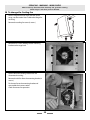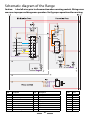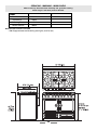
1
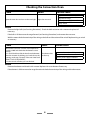
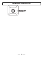
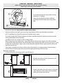
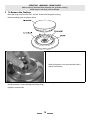
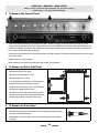
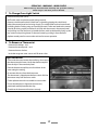
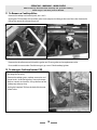
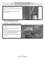
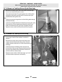
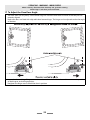
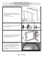
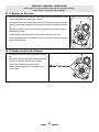
This book contains many important safety messages. Always read and obey all safety messages. Installer:Leave these instructions with the range Important - Save the installation instructions for the local electrical inspector’s use. CornuFé 44 Dual Fuel Range Service Instructions F107150-01 WARNING If the information in this manual is not followed exactly, a fire or explosion may result causing property damage, personal injury or death. Do not store or use gasoline or other flammable vapors and liquids in the vicinity of this or any other range. WHAT TO DO IF YOU SMELL GAS Do not try to light any range. Do not touch any electrical switch Do not use any phone in your building. Immediately call your gas supplier from a neighbor’s phone. Follow the gas supplier’s instructions. If you cannot reach your gas supplier, call the fire department. Installation and service must be performed by a qualified installer, service agency or the gas supplier. WARNING The anti-tip device supplied with this range must be correctly fitted when the range is installed. This will reduce risk of tipping of the range from abnormal usage or by excessive loading of the oven door WARNING • • • • ALL RANGES CAN TIP INJURY TO PERSONS COULD RESULT INSTALL ANTI-TIP BRACKET PACKED WITH RANGE SEE INSTALLATION INSTRUCTIONS SERVICING WARNING WORK SAFELY Where necessary disconnect from electricity and gas before starting. Check range is safe when you have finished. Sections Diagnostics 5 Servicing Section 12 Schematic diagram of the Range 31 Technical Data 32 3 SERVICING WARNING WORK SAFELY Where necessary disconnect from electricity and gas before starting. Check range is safe when you have finished. Servicing Notes When servicing or replacing gas carrying components disconnect from gas before commencing operation and check range is gas sound after completion. When checking for gas leaks use a liquid leak detector at all joints and connections to check for leaks in the system. Use a product specifically manufactured for leak detection. Leak testing of the range shall be conducted in accordance to the manufacturer’s instructions. CAUTION: DO NOT USE A FLAME TO CHECK FOR GAS LEAKS. When using test pressures greater than ½ psig (3.5kPa) to pressure test the gas supply system of the residence, disconnect the range and individual shut-off valve from the gas supply piping. When using test pressures of ½ psig (3.5kPa) or less to test the gas supply system, simply isolate the range from the gas supply system by closing the individual shut-off valve. Do not use re-conditioned or unauthorized gas controls. Disconnect from electricity supply before commencing servicing, particularly before removing any of the following: control panel, side panels, cooktop tray, or any of the electrical components or cover boxes. Before electrical reconnection make sure the range is electrically safe. Note – If not specifically stated, references to left hand and right hand oven are as viewed from the front of the range. 4 SERVICING WARNING WORK SAFELY Where necessary disconnect from electricity and gas before starting. Check range is safe when you have finished. Diagnostics Checking the Multifunction Oven 6 Checking the Convection Oven 8 Checking the Cooktop 10 5 Checking the Multifunction Oven Check Result Possible Cause Light bulb failed (most likely cause) Open the oven door and turn on the oven light Light does not work No power to range Fault in power supply to switch Faulty switch Action Remove the light bulb (see ‘Servicing Procedures’). Check the bulb resistance with a meter and replace it if necessary. If the bulb is OK then move the range forward (see ‘Servicing Procedures’) and remove the rear cover. With the meter check the continuity of the wiring to the bulb and the action of the switch. Replace wiring or switch as necessary. Check Result Possible Cause Fault in power supply to switch Faulty switch Turn the function control to the Defrost setting and check that the oven fan starts to spin. Fan does not spin Fault in power supply to fan Fan motor faulty Fan blades impeded Action Remove the oven inner back and check that the fan is not impeded. If not then move the range forward (see ‘Servicing Procedures’) and remove the rear cover. With the meter check the continuity of the wiring to the fan and the action of the switch. Replace wiring, switch or fan as necessary. Check Remove the oven racks. Turn the oven temperature control to 400F and turn the function control to each setting in turn and check that the elements start to heat up. See the chart opposite. You should be able to feel the heat from the element after few moments by holding your hand close to the element (DON’T TOUCH THE ELEMENTS!). The bottom element may take slightly longer to heat up. Turn the controls off when you have finished. Result Possible Cause Burnt out element (most likely cause) One element does not heat up. Faulty switch Fault in power supply to element Faulty oven thermostat.(most likely cause) No element heats up Faulty switch Fault in power supply to elements Action One element not working No element working Remove the element and check it with a meter. Replace with a new element if necessary. If the element is OK then move the range forward and check the continuity of the wiring and the function switch 6 Remove the range cooktop and check the thermostat and fuction switch Checking the Multifunction Oven 7 Checking the Convection Oven Check Result Possible Cause Light bulb failed (most likely cause) Open the oven door and turn on the oven light Light does not work No power to range Fault in power supply to switch Faulty switch Action Remove the light bulb (see ‘Servicing Procedures’). Check the bulb resistance with a meter and replace it if necessary. If the bulb is OK then move the range forward (see ‘Servicing Procedures’) and remove the rear cover. With the meter check the continuity of the wiring to the bulb and the action of the switch. Replace wiring or switch as necessary. Check Result Remove the oven racks. Turn the oven temperature control to 400F and check that the element start to heat up. You should be able to feel the heat from the element The element does after few moments by holding your hand close to the not heat up. openings at the top or bottom of the oven inner back. (DON’T TOUCH THE ELEMENT!). Turn the controls off when you have finished. Possible Cause Burnt out element (most likely cause) Faulty switch Fault in power supply to element Action Remove the element and check it with a meter. Replace with a new element if necessary. If the element is OK then move the range forward and check the continuity of the wiring and the thermostat. 8 Checking the Convection Oven 9 Checking the Cooktop Range Maintop Ignition The maintop burners have spark ignition operated by a switch on each control valve. When any burner control knob is pressed in the spark generator module produces sparks at all the burners ignition electrodes. Problem Check The ignition system Try lighting the burner with a match. makes sparks but does Are the flames even around the head with a blueish color? not light the gas Check the burner head is clean and the flame ports are clear. Check that the burner head is sitting down correctly on the burner base. What gas is being used? The range is supplied set for Natural Gas. It must be converted before it can be used on LP gas. The ignition system does not make sparks. Use flow chart below to check out the ignition system 10 Checking the Cooktop Problem Check The burner lights but the flame goes out when the control knob is released Each burner gas control valve includes a thermoelectric solenoid flame safety valve (FSD) that is normally closed. There is a sensor probe mounted on each burner. To light a burner the user must push in the control knob and turn to the full on position. Pushing in the knob overrides the safety valve and allows gas to flow to the burner while the knob is pushed in. The spark ignition lights the burner and the flame heats the sensor probe. When it gets hot enough the sensor produces a very low voltage electric current that keeps the safety valve open when the control knob is released. Try holding the knob in for longer. The FSD should hold in after a few seconds, if it does not hold in after 10 seconds the sensor may not be getting hot enough because there is problem with the burner head or the sensor position is incorrect. Check the burner head is clean and the flame ports are clear. Check that the burner head is sitting down correctly on the burner base If this does not solve the problem try changing the sensor probe The burner flame goes out when the control is turned to low. Check that the burner control valve is fitted with the correct bypass screw. See the ‘Technical Data’ section at the end of this book. Try changing the bypass screw for a new one. The burner flames are very yellow What gas is being used? The range is supplied set for Natural Gas. It must be converted before it can be used on LP gas. The burner flames are very small and blue. What gas is being used? The range is supplied set for Natural Gas. If it has been converted for use on LP gas it must be reconverted by changing the burner orifices and control valve bypass screws before it can be used on Natural Gas The pattern of flames on the burner is not even Check the burner head is clean and the flame ports are clear. Check that the burner head is sitting down correctly on the burner base 11 Servicing Section 1 How to change an oven light bulb 13 2 How To Move the Range for Servicing 13 3 To Remove the Cooktop 15 4 To Remove the Control Panel 16 5 To Remove an Outer Side Panel 16 6 To Remove an Oven Neon 16 7 To Change Oven Light Switch 17 8. To Remove a Thermostat 17 9 To Change a Multifunction oven function switch 18 10 To Remove an Oven element Thermal Cut-Out. 18 11 To Remove a Cooktop Valve 19 12 To change a Cooktop burner FSD 19 13 To Change an Ignition Switch 20 14 To Remove a Cooktop Burner Orifice 20 15 To Remove a Cooktop Burner Spark Electrode 21 16 To Remove a Cooktop Burner Body 21 17 To Adjust the Oven Door Angle 22 18 To Change the Oven Outer Door Panel or Door Trim Parts 23 19 To Remove an Oven Door 24 20 To Replace a Door Inner Panel 24 21 To Remove the Door Latch 25 22 To Remove the Oven Door Seal 25 23 To Adjust the Oven Door Catch Keeper 25 24 To Remove the Cooktop Spark Generator 26 25 To Remove the Cooktop Electrode Leads 26 26 To Remove Oven Inner Back 26 27 To Replace an Oven Fan 27 28 To Remove an Oven fan Element 27 29 To Remove the Left Hand Multifunction Oven Bottom and Top Elements 28 30 To change the Cooling fan 29 12 SERVICING WARNING WORK SAFELY Where necessary disconnect from electricity and gas before starting. Check range is safe when you have finished. 1 How to change an oven light bulb Replacement bulb must be 15w 125-130v lamp, FOR OVENS, heat resistant to 300°C (570°F). Turn off the power at the circuit breaker Make sure the oven is cool. Open the oven door and remove the oven racks. Unscrew the bulb cover by turning counter clockwise. It may be very stiff. Taking care to protect your fingers in case the bulb should shatter, unscrew the old bulb. Screw in the new bulb, screw back the bulb cover. Turn on the circuit breaker and check that the bulb now lights. 2 How To Move the Range for Servicing Follow these procedures to move the range for servicing: Shut off the gas supply and disconnect electrical supply to appliance. Disconnect gas supply tubing to appliance and unplug the electrical supply cord. NOTE: A qualified person should disconnect and reconnect the gas supply. The range is very heavy. Take great care. We recommend two people manoeuvre the range. Ensure that the floor covering is firmly attached, or removed to prevent it being disturbed when moving the range around. You will need the leveling tool. Lift up the ends of the plastic clips (one each side) to release the catches holding the drawer to the side runners and at the same time pull the drawer forward and away from the side runners. Pull the drawer out to its furthest point and empty it. For safety’s sake push the drawer runners back out of the way. Put the drawer somewhere safe - do not refit it until you have finished, you will need access to the area behind the drawer. 13 SERVICING WARNING WORK SAFELY Where necessary disconnect from electricity and gas before starting. Check range is safe when you have finished. Fit the Allen key tool to the center roller lowering mechanism (C in the fig.). Lower the front roller by turning the Allen key clockwise until the front feet are just clear of the floor. A left rear roller, B right rear roller, C center roller Open both oven doors and with your hands griping under the control panel slide, the range forward to disengage from the anti-tip bracket. Do not pull the range by the handrail. Reverse procedure to reinstall. If gas line has been disconnected, check for gas leaks after re-connection. NOTE: A qualified person should disconnect and reconnect the gas supply. The service engineer MUST follow installation instructions provided with the gas appliance connector and the warning label attached to the connector. CAUTION: DO NOT USE A FLAME TO CHECK FOR GAS LEAKS. When using test pressures greater than ½ psig (3.5kPa) to pressure test the gas supply system of the residence, disconnect the range and individual shut-off valve from the gas supply piping. When using test pressures of ½ psig (3.5kPa) or less to test the gas supply system, simply isolate the range from the gas supply system by closing the individual shut-off valve. If the range is removed for any reason, make sure the anti-tip device is re-engaged properly when the range is replaced. Failure to take this precaution could result in tipping of the range and cause injury. Replace the storage drawer To replace the drawer in the range, pull the side rails fully out. Carefully move the drawer back between the rails and rest it on the side rails. At each side hold the front of the drawer and pull the side rail forward so that the clips click into position holding the drawer to the side rails. 14 SERVICING WARNING WORK SAFELY Where necessary disconnect from electricity and gas before starting. Check range is safe when you have finished. 3 To Remove the Cooktop Move the range away from the wall - see ‘How To Move the Range for Servicing’. Remove cooktop grates and burner heads. Undo the large brass nuts and remove the brass venturis and washers. Lift up the front of the cooktop top and prop it up. Disconnect the ignition leads from the electrodes and remove the burner bezels. Lift the cooktop clear of the range. Replace in reverse order. 15 SERVICING WARNING WORK SAFELY Where necessary disconnect from electricity and gas before starting. Check range is safe when you have finished. 4 To Remove the Control Panel Remove all the control knobs. Open both oven doors. Remove 3 fixings on the top front and 3 fixings on the control panel underside. Pull the control panel forward. It may be difficult to move the control panel because it is held by the cooktop. If so loosen the cooktop by removing the cooktop grates and burner heads and slacken the brass venturi at the centre of each burner. Remove the connections from the rear of the neons and light switches. Disconnect the earth lead and lift the panel clear of the range. Replace all parts in reverse order. When replacing any electrical connections refer to the wiring diagram. 5 To Remove an Outer Side Panel Move the range away from the wall - see ‘How To Move the Range for Servicing’. Remove the control panel – see 2. Remove the plinth, 3 screws. If a side extension is fitted it must be removed before the side panel can be unscrewed. Undo the lower retaining screw situated below the edge at the panel front corner. Remove the 2 front side panel retaining screws and the 2 on the rear of the side panel. Remove the panel by pulling it away from the range. 6 To Remove an Oven Neon Remove the control panel – see 2. Remove the relevant neon connections and undo the nut which secures the neon to the control panel. Replace parts in reverse order. Ensure the replacement neon functions correctly. 16 SERVICING WARNING WORK SAFELY Where necessary disconnect from electricity and gas before starting. Check range is safe when you have finished. 7 To Change Oven Light Switch Remove control panel (see 2). NB The old switch may be destroyed during removal. Remove switch button and old switch from its bezel by gripping the switch body behind the control panel and twisting sharply. The switch bezel can then be removed by folding back its locking wings and pushing forward. Fit the new bezel to the control panel by first lining up the raised key on its body with the cutout in the control panel and pushing it in from the front. Assemble the new switch to the bezel by lining up the key sections and pushing home. Fit the new button by pushing in from the front. Replace control panel in reverse order and test for correct operation. 8. To Remove a Thermostat Remove the cooktop - see 1. Remove the control panel - see 2 Remove the oven shelves. Undo the range rear cover screws and lift covers clear. Right Hand oven From inside the oven remove the two fixings that secure the thermostat phial cover. Unclip the thermostat phial from the clips in the oven back panel. Feed the thermostat capillary out of and clear of the oven noting the routing. Disconnect the wires from the thermostat. The thermostat is clipped onto the front switch. Pull the thermostat away from the front switch. Fit the replacement and re-assemble in reverse order. Ensure that the phial is clipped to the oven rear, positioned centrally between the clips. Check that the thermostat functions correctly. 17 SERVICING WARNING WORK SAFELY Where necessary disconnect from electricity and gas before starting. Check range is safe when you have finished. Left Hand Multifunction oven From inside the oven remove the two screws holding the thermostat phial to the oven fan cover at the rear of the oven. Feed the thermostat capillary out of and clear of the oven noting the routing. Disconnect the wires from the thermostat and undo the two fixings which secure the control to the mounting plate. Fit the replacement and re-assemble in reverse order. Ensure that the phial is clipped to the oven rear, positioned centrally between the clips. Check that the thermostat functions correctly 9 To Change a Multifunction oven function switch Move the range away from the wall - see ‘How To Move the Range for Servicing’. Remove the cooktop grates, cooktop accessories and burner heads. Undo the large brass nuts and remove the brass venturis and washers. Lift up the front of the cooktop top and prop it up. Remove the control panel see section 2. Remove the fixing screws from the front of the Multifunction oven function switch, disconnect the leads and remove the switch. Fit the new switch. Reassemble in reverse order and check that the oven operates correctly. 10 To Remove an Oven element Thermal Cut-Out. Note There is one thermal cutout on the fan oven, 2 on the Multifunction oven. Pull the range forward to gain access rear, see the section ‘How To Move the Range for Servicing’. Undo the rear cover screws and lift cover clear. There is one thermal cutout on the fan oven and 2 on the Multifunction oven. The cutouts are located on the earth plates beside the oven element connections. Disconnect the cutout wiring. Undo the fixings that secure the cutout to the earth plate and remove. Fit replacement control and re-assemble in reverse order. Back of Multifunction oven 18 SERVICING WARNING WORK SAFELY Where necessary disconnect from electricity and gas before starting. Check range is safe when you have finished. 11 To Remove a Cooktop Valve Remove the cooktop and control panel, see 1 and 2. Unplug the FSD lead from the rear of the valve. Undo compression fitting at the rear of the valve. Remove the fixings that secure the valve to the gas rail. Disconnect the ignition switch wiring. Remove the valve. Remove and discard the gasket seal. Fit new gasket seal to replacement valve. Re-assemble in reverse order. Check the range is gas sound. Check cooktop ignition. 12 To change a Cooktop burner FSD Move the range away from the wall - see ‘How To Move the Range for Servicing’. Remove the cooktop grates, cooktop accessories and burner heads. Undo the large brass nuts and remove the brass venturis and washers. Lift up the front of the cooktop top and prop it up. Unplug the hotplate FSD from the back of the burner control valve. 19 SERVICING WARNING WORK SAFELY Where necessary disconnect from electricity and gas before starting. Check range is safe when you have finished. Remove the nut holding the nut holding FSD probe to the burner mounting cross member. Fit the new FSD probe, plug into the back of the control valve Reassemble in reverse order and check for correct burner operation. 13 To Change an Ignition Switch Change the gas valve as detailed in Section 9. 14 To Remove a Cooktop Burner Orifice Remove the cooktop grate and burner head. Undo the large brass nut and remove the brass venturi. The orifice is now accessible using a long box spanner. Alternatively, remove the cooktop as detailed in Section 1. Remove the orifice directly from the burner body. Fit the appropriate orifice. Re-assemble in reverse order. Check the range is gas sound. 20 SERVICING WARNING WORK SAFELY Where necessary disconnect from electricity and gas before starting. Check range is safe when you have finished. 15 To Remove a Cooktop Burner Spark Electrode Remove the cooktop grate and burner head. Undo the large brass nut and remove the brass venturi. Lift up the burner bezel. The spark ignition wire will be pulled through the electrode clearance hole. Disconnect the spark electrode from the ignition wire. Note Take care to prevent the ignition wire from falling back through the clearance hole. Undo the spark electrode from the bezel by removing the spring clip and spring. Fit the replacement electrode to the burner bezel. Ensure that the spring and clip are properly located. Replace in reverse order and check correct burner ignition. 16 To Remove a Cooktop Burner Body Remove the cooktop grates, cooktop accessories and burner heads. Remove the cooktop as detailed in Section 1. Remove the nut that secures the burner body to the support channel. Remove the fixings that secure the support channel to the chassis. Lift the channel clear of the range. Undo the compression fitting which connects the burner body to the gas pipe. Remove the burner body from the range. Remove the orifice for the old burner and fit it to the new burner body. Replace in reverse order. Check the range is gas sound and that the burner operates satisfactorily. 21 SERVICING WARNING WORK SAFELY Where necessary disconnect from electricity and gas before starting. Check range is safe when you have finished. 17 To Adjust the Oven Door Angle The oven doors are very heavy. Transit of the range can cause the oven doors to move so that they are not correctly aligned. Both oven doors are fitted with adjustable door bottom hinges. The hinges can be adjusted to alter the angle of the door. Loosen the bottom hinge fixing screws and use the notch and a flat bladed screwdriver to move the position of the hinge to set the hinge position. Retighten the hinge screws to hold the door in position. 22 SERVICING WARNING WORK SAFELY Where necessary disconnect from electricity and gas before starting. Check range is safe when you have finished. 18 To Change the Oven Outer Door Panel or Door Trim Parts The door outer panel and all the trim parts are available as separate parts so that individual parts can be changed. Door is very heavy - take care. Unscrew the door handle and remove the handle and door trim handle disk.. Open the oven door. Remove the hexagon headed screws ‘A’ and ‘B’ (two each side) from the door. Carefully lift of the door outer. Place the outer panel on a clean flat surface. As can be seen in the photograph the door trim handle plate is held in place by screws on the inside. Studs and nuts hold the other trims. Replace the damaged parts and re-assemble in reverse order. 23 SERVICING WARNING WORK SAFELY Where necessary disconnect from electricity and gas before starting. Check range is safe when you have finished. 19 To Remove an Oven Door Door is very heavy - take care. Open the oven door. Loosen the two top hinge screws. Support the weight of the door and remove the screw nearest the hinge pin. Swing the hinge up and away from the hinge pin on the door. Lift the door away from the bottom hinge. Re-assemble in reverse order. When replacing the door ensure that the nylon hinge bush is in position between the hinge pin and the hinge bracket at the both the bottom and top. 20 To Replace a Door Inner Panel The door inner panel is supplied fully assembled. Remove the door – see Section 19. Carefully place the door, outer side up, on a clean level surface. Remove the hexagon headed screws, two each side, from the door edges. Carefully lift off the door outer panel. Fit the door front to the new inner panel and reassemble in reverse order 24 SERVICING WARNING WORK SAFELY Where necessary disconnect from electricity and gas before starting. Check range is safe when you have finished. 21 To Remove the Door Latch Remove the oven outer door panel as detailed in Section 18. Remove the fixings that secure the latch assembly to the inner door panel. Fit the replacement catch and re-assemble in reverse order. Check correct operation of door. 22 To Remove the Oven Door Seal Open oven door. The seal is held in place by small hooks on the rear face. At the corner pull seal diagonally away from the door centre until that hook is released. Proceed to the next hook and release it in a similar way, and so on. Use force if the hooks are stiff, as the old seal will be discarded. When fitting new seal, position the seal join at the bottom. Hook the new seal in one of the corner holes of the door, and proceed round the door snapping in each hook in turn. 23 To Adjust the Oven Door Catch Keeper Open the oven door and slacken the locknut at the keeper base. Adjust the keeper inward or outward as required, until the desired door operation is obtained. Check the door seal with a strip of paper. Re-tighten the locknut. 25 SERVICING WARNING WORK SAFELY Where necessary disconnect from electricity and gas before starting. Check range is safe when you have finished. 24 To Remove the Cooktop Spark Generator Pull the range forward to access the covers at the rear of the range; see the section ‘How To Move the Range for Servicing’. From the rear remove the right hand (when viewed from the rear) rear cover and disconnect all the leads at the generator. Fit the leads to the new generator Undo the fixings that secure the spark generator and remove the device and fit the new one. Re-assemble in reverse order. Check that the ignition works correctly 25 To Remove the Cooktop Electrode Leads Pull the range forward to access the covers at the rear of the range, see the section ‘How To Move the Range for Servicing’. Remove the cooktop grates, cooktop accessories and burner heads. Lift up the front of the cooktop top and prop it up. From the rear remove the right hand (when viewed from the rear) rear cover and disconnect all ignition electrode leads at the generator. Disconnect the leads at the electrodes. Pull the bundle of electrode HT leads up through the rear upright. Place the new leads in the rear upright. Re-connect the leads at the generator and burner electrodes. Re-assemble in reverse order and check ignition. 26 To Remove Oven Inner Back Open the oven door. For the left hand oven unscrew the 2 thermostat phial fixing screws. Remove the fixings that secure the inner back to the oven rear. Lift the removable panel away. Re-assemble in reverse order. Ensure that the retaining fixings are fully tightened. 26 SERVICING WARNING WORK SAFELY Where necessary disconnect from electricity and gas before starting. Check range is safe when you have finished. 27 To Replace an Oven Fan Pull the range forward to access the cover boxes at the rear of the range, see the section ‘How To Move the Range for Servicing’. Remove the fixings that secure the cover and lift it clear. Remove the fan wiring, noting the connection positions. Remove the inner back as detailed in Section 26. Hold the fan blades and undo the centre nut (left hand thread), brass washers, fan blade and Circlip. Undo the fixings that retain the fan and remove it from the cavity rear. Fit the replacement and re-assemble parts in reverse order. Check that the oven operates satisfactorily. 28 To Remove an Oven fan Element Remove the oven inner back as detailed in Section 26. Remove the fixings that secure the element within the oven and lift the element away carefully. Disconnect the leads and connect to the replacement element and re-assemble parts in reverse order. 27 SERVICING WARNING WORK SAFELY Where necessary disconnect from electricity and gas before starting. Check range is safe when you have finished. 29 To Remove the Left Hand Multifunction Oven Bottom and Top Elements Bottom Element Pull the range forward to access the rear of the range, see the section ‘How To Move the Range for Servicing’. Remove the fixings that secure the right hand (when viewed from the rear) cover and lift it clear. Remove the 2 screws ‘A’ and allow the plate to drop down. Remove the 2 screws B, lower the upper plate and remove through the slot in the range back. Undo the terminal connections, noting their positions. Remove the element fixings and withdraw element. Replace the element and re-assemble parts in reverse order. Top Element Open the left hand oven door and undo the fixings that secure the heat shield and remove the shield. Remove the top element bracket fixings and withdraw element. Replace the element and re-assemble parts in reverse order. Check that the oven operates satisfactorily. 28 SERVICING WARNING WORK SAFELY Where necessary disconnect from electricity and gas before starting. Check range is safe when you have finished. 30 To change the Cooling fan Pull the range forward to access the rear of the range, see the section ‘How To Move the Range for Servicing’. Remove the cooling fan cover (4 screws) Remove the 6 screws holding the fan mounting bracket to the range back. Pull the fan and mounting bracket out and disconnect the wiring. Remove the old fan from the mounting bracket (4 screws). Fit the new fan to the mounting bracket and reassemble the in reverse order. Check for correct fan operation. 29 SERVICING WARNING WORK SAFELY Where necessary disconnect from electricity and gas before starting. Check range is safe when you have finished. 30 Schematic diagram of the Range Caution: Label all wires prior to disconnection when servicing controls. Wiring errors can cause improper and dangerous operation. Verify proper operation after servicing. Code Description Code Description Code Color CFM IGS ISG LBE LFE LTI LTO LOS Cooling fan motor Ignition switches Ignition spark generator Left hand bottom element Left hand fan element Left hand top inner element Left hand top outer element Left hand oven switch block OFM OLS OTL OTR OVL ROE RSB TCO Oven fan motor Oven light switch Left hand oven thermostat Right hand oven thermostat Oven light bulb Right hand oven element Right hand oven switch block Thermal cut out NLI Neon indicator light BK BL BR GY O R V W Y Black Blue Brown Grey Orange Red Violet White Yellow 31 SERVICING WARNING WORK SAFELY Where necessary disconnect from electricity and gas before starting. Check range is safe when you have finished. Technical Data This range is supplied set for Natural gas. A conversion kit from Natural Gas to Propane gas is included. INSTALLER: Please leave these instructions with the User. DATA BADGE LOCATION: instructions. Inside base of drawer cavity - remove drawer. For removal of drawer see installation Country of Destination: USA/Canada Gas Electric Natural Gas 4.0” W.C (10 mbar) Propane 10.0” W.C (25 mbar) 240V 60Hz (See appliance data badge for test pressures) Dimensions Overall height minimum 35 13/16” (91 cm) Overall width 43” (109.2cm) See ‘Positioning the Range’ Overall depth 28 5/8” (72 .5cm). Space for fixing See ‘Positioning the Range’ Minimum space above cooktop 31.5” (80cm) Connections Gas : maximum 36 7/8” (93.7 cm) Electric: ½” NPT at rear right-hand side 240 V 60 Hz Ratings Cooktop Natural Gas Input Propane Gas Orifice Screw Input Orifice Screw Center burner 17,500 Btu/hr 205 82 17,500 Btu/hr 118 49 Large Burners 12,000 Btu/hr 150 70 12,000 Btu/hr 99 38 Right hand front Burner 6,000 Btu/hr 112 53 6,000 Btu/hr 68 31 Gas burner inputs based on Gross Calorific Value 32 SERVICING WARNING WORK SAFELY Where necessary disconnect from electricity and gas before starting. Check range is safe when you have finished. Ovens Left hand Multifunction Oven Fan element Top element Browning Element Bottom element Right hand Convection Oven 2500W 1200W 1150W 1000W 2500W Maximum total electrical load at 240V 5100 W (approximate total including oven lights, oven fan etc.) 33 060106