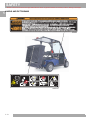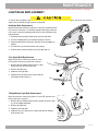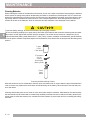
1
Owner’s Guide 624263 ISSUED OCTOBER 2011 WELCOME Thank you for purchasing this vehicle. Before driving the vehicle, we ask you to spend some time reading this Owner’s Guide. This guide contains the information that will assist you in maintaining this highly reliable vehicle. Some illustrations may show items that are optional for your vehicle. This guide covers the operation of several vehicles; therefore, some illustrations may not represent your vehicle. Physical differences in controls will be illustrated. Most of the service procedures in this guide can be accomplished using common, automotive hand tools. Contact your service representative on servicing the vehicle in accordance with the Periodic Service Schedule. Repair or replacement parts are available through your E-Z-GO retailer or E-Z-GO Genuine Service Parts. The following information is needed when contacting E-Z-GO concerning service or parts for your vehicle: Vehicle Model ____________________________________________________________________________ VIN Number _____________________________________________________________________________ Manufacturing Date Code __________________________________________________________________ NOTICE CUSHMAN LSV 800 is a motor vehicle that can only be operated by a licensed driver, and must be driven in accordance with all State traffic laws and the insurance requirements for motor vehicles. FOREWORD Read all of this manual to become thoroughly familiar with this vehicle. Pay particular attention to all Notices, Cautions, Warnings, and Dangers. OWNER’S GUIDE 48 V ELECTRIC POWERED LOW-SPEED VEHICLE LSV 800 STARTING MODEL YEAR 2012 Never modify the vehicle in any way that will alter the weight distribution of the vehicle, decrease its stability or increase the speed beyond the factory specifications. Such modifications can cause serious personal injury or death. E-Z-GO Division of Textron, Inc. prohibits and disclaims responsibility for any such modifications or any other alteration which would adversely affect the safety of the vehicle. E-Z-GO Division of Textron, Inc. reserves the right to incorporate engineering and design changes to products in this manual, without obligation to include these changes on units sold previously. The information contained in this manual may be revised periodically by E-Z-GO Division of Textron, Inc., and therefore is subject to change without notice. E-Z-GO Division of Textron, Inc. DISCLAIMS LIABILITY FOR ERRORS IN THIS MANUAL, and SPECIFICALLY DISCLAIMS LIABILITY FOR INCIDENTAL AND CONSEQUENTIAL DAMAGES resulting from the use of the information and materials in this Manual. TO CONTACT US E-Z-GO Division of Textron Inc. 1451 Marvin Griffin Road. Augusta, Georgia, USA 30906-3852 North America: Technical Assistance & Warranty PHONE: 1-800-774-3946 FAX: 1-800-448-8124 Service Parts PHONE: 1-888-GET-EZGO (1-888-438-3946) FAX: 1-800-752-6175 International: Page i FOREWORD Read all of this manual to become thoroughly familiar with this vehicle. Pay particular attention to all Notices, Cautions, Warnings, and Dangers. This vehicle has been designed and manufactured in the United States of America (USA). The Standards and Specifications listed in the following text originate in the USA unless otherwise indicated. The use of non-Original Equipment Manufacturer (OEM) approved parts may void the warranty. Failure to properly maintain batteries may void the warranty. Refer to the battery manual for instructions on the proper maintenance and care of the batteries. BATTERY PROLONGED STORAGE All batteries will self-discharge over time. The rate of self-discharge varies depending on the ambient temperature, the age and condition of the batteries. A fully charged battery will not freeze in winter temperatures unless the temperature falls below -75°F (- 60°C). For winter storage, the batteries must be clean, fully charged and disconnected from any source of electrical drain. The battery charger may be left connected to the vehicle to maintain a full charge on the batteries, provided the charger is plugged into an active electrical source. If power to the electrical source is disconnected or interrupted the battery charger will continue to check the charge on the battery pack, this will draw power from the battery pack and eventually drain the batteries if power is not restored in a timely manner. As with all electric vehicles, the batteries must be checked and recharged as required or at a minimum of 30 day intervals. Page ii TABLE OF CONTENTS Read all of this manual to become thoroughly familiar with this vehicle. Pay particular attention to all Notices, Cautions, Warnings, and Dangers. SECTION PAGE NO. SAFETY............................................................................................................................................................................... 1-1 GENERAL SPECIFICATIONS............................................................................................................................................. 2-1 INTRODUCTION.................................................................................................................................................................. 3-1 OPERATING PROCEDURES.............................................................................................................................................. 4-1 MAINTENANCE................................................................................................................................................................... 5-1 REGISTRATION AND WARRANTY .................................................................................................................................... 6-1 Page iii TABLE OF CONTENTS Read all of this manual to become thoroughly familiar with this vehicle. Pay particular attention to all Notices, Cautions, Warnings, and Dangers. Notes: Page iv SAFETY Read all of this manual to become thoroughly familiar with this vehicle. Pay particular attention to all Notices, Cautions, Warnings, and Dangers. TITLE PAGE NO. SAFETY................................................................................................................................................................. 1-3 NOTICES, CAUTIONS, WARNINGS, AND DANGERS......................................................................................... 1-3 GENERAL ............................................................................................................................................................. 1-4 GENERAL OPERATION ....................................................................................................................................... 1-5 MAINTENANCE .................................................................................................................................................... 1-6 VENTILATION ....................................................................................................................................................... 1-6 SEAT BELTS......................................................................................................................................................... 1-7 LABELS AND PICTOGRAMS ............................................................................................................................... 1-8 REPORTING SAFETY DEFECTS ......................................................................................................................... 1-9 1- 1 1 SAFETY Read all of this manual to become thoroughly familiar with this vehicle. Pay particular attention to all Notices, Cautions, Warnings, and Dangers. 1 Notes: 1- 2 SAFETY Read all of this manual to become thoroughly familiar with this vehicle. Pay particular attention to all Notices, Cautions, Warnings, and Dangers. SAFETY 1 For any questions on material contained in this manual, contact an authorized representative for clarification. Read and understand all labels located on the vehicle. Always replace any damaged or missing labels. On steep hills it is possible for vehicles to coast at greater speeds. To prevent loss of vehicle control and possible serious injury, speeds should be limited to no more than 25 mph. Catastrophic damage to the drivetrain components due to excessive speed may result from driving the vehicle above 25 mph. Damage caused by excessive speed may cause a loss of vehicle control, is costly, is considered abuse, and will not be covered under warranty. Signs similar to the ones illustrated should be used to warn of situations that could result in an unsafe condition. BATTERY WARNING Battery posts, terminals and related accessories contain lead and lead compounds, chemicals known to cause cancer and reproductive harm. WASH HANDS AFTER HANDLING! BATTERIES CONTAIN LEAD AND RELATED PARTS ! < 14˚ 25% DO NOT DRIVE ACROSS SLOPES IN EXCESS OF 14˚ WASH HANDS AFTER HANDLING! WARNING: Battery posts, terminals and related accessories contain lead and lead compounds, chemicals known to cause cancer and reproductive harm. Observe these NOTICES, CAUTIONS, WARNINGS and DANGERS; be aware that servicing a vehicle requires mechanical skill and a regard for conditions that could be hazardous. Improper service or repair may damage the vehicle or render it unsafe. NOTICES, CAUTIONS, WARNINGS, AND DANGERS Throughout this guide NOTICE, CAUTION, WARNING, and DANGER will be used. Please observe these NOTICES, CAUTIONS, WARNINGS, and DANGERS; be aware that servicing a vehicle requires mechanical skill and a regard for conditions that could be hazardous. Improper service or repair may damage the vehicle or render it unsafe. NOTICE Address practices not related to personal injury. Indicates a hazardous situation which, if not avoided, could result in minor or moderate injury. Indicates a hazardous situation which, if not avoided, could result in death or serious injury. DANGER Indicates a hazardous situation which, if not avoided, will result in death or serious injury. 1- 3 SAFETY Read all of this manual to become thoroughly familiar with this vehicle. Pay particular attention to all Notices, Cautions, Warnings, and Dangers. 1 This manual has been designed to assist in maintaining the vehicle in accordance with procedures developed by the manufacturer. Adherence to these procedures and troubleshooting tips will ensure the best possible service from the product. To reduce the chance of personal injury or property damage, the following must be carefully observed: THE LSV 800 SHALL BE OPERATED ONLY BY PERSONS WITH VALID DRIVERS LICENSES, AND IN ACCORDANCE WITH APPLICABLE STATE REQUIREMENTS. THIS IS A LEGAL REQUIREMENT AND IS IMPORTANT TO THE SAFE USE AND OPERATION OF THE PRODUCT. All customers should adhere to this SAFETY RESTRICTION, in connection with the use of all E-Z-GO products, new and used, in personal transportation applications. Federal Low-Speed Vehicle Standard (FMVSS 571.500) can be obtained at Title 49 of the Code of Federal Regulations, section 571.500, or through the Internet at the website for the U.S. Department of Transportation - at Dockets and Regulation, then to Title 49 of the Code of Federal Regulations (Transportation). All vehicles can be used for a variety of tasks often beyond the original intended use of the vehicle; therefore, it is impossible to anticipate and warn against every possible combination of circumstances that may occur. No warning can replace good common sense and prudent driving practices. GENERAL Good common sense and prudent driving practices do more to prevent accidents and injury than all of the warnings and instructions combined. E-Z-GO strongly suggests that all users and maintenance personnel read this entire manual paying particular attention to the CAUTIONS, WARNINGS and DANGERS contained therein. If you have any questions regarding this vehicle, contact your E-Z-GO dealer or write to the address on the back cover of this publication, Attention: Customer Care Department. E-Z-GO reserves the right to make design changes without obligation to make these changes on units previously sold. The information contained in this manual is subject to change without notice. E-Z-GO IS NOT LIABLE FOR ERRORS IN THIS MANUAL. E-Z-GO IS NOT LIABLE FOR INCIDENTAL OR CONSEQUENTIAL DAMAGES THAT RESULT FROM THE USE OF THE MATERIAL IN THIS MANUAL. This vehicle is designed and manufactured in accordance with FMVSS 571.500. Be sure that all electrical accessories are grounded directly to the battery (-) post. Never use the chassis or body as a ground connection. Refer to GENERAL SPECIFICATIONS for vehicle seating capacity. Never modify the vehicle in any way that will alter the weight distribution of the vehicle, decrease its stability or increase the speed or extend the stopping distance beyond the factory specification. Such modifications can result in serious personal injury or death. Do not make any such modifications or changes. E-Z-GO prohibits and disclaims responsibility for all such modifications or and alterations which would adversely affect the safety of the vehicle. Vehicles that are capable of higher speeds must limit their speed to no more than the speed of other vehicles when used in a golf course environment. Additionally, speed should be further moderated by the environmental conditions, terrain and common sense. 1- 4 SAFETY Read all of this manual to become thoroughly familiar with this vehicle. Pay particular attention to all Notices, Cautions, Warnings, and Dangers. GENERAL OPERATION 1 Read the following warnings before attempting to operate the vehicle. To prevent personal injury or death, observe the following: When vehicle is to be left unattended, turn key to OFF position AND REMOVE KEY. Drive vehicle only as fast as terrain and safety considerations allow. Consider the terrain and traffic conditions. Consider environmental factors which affect the terrain and the ability to control the vehicle. Avoid driving fast downhill. Sudden stops or change of direction may result in a loss of control. Use brake to control speed when traveling down an incline. Use extra care and reduced speed when driving in poor driving conditions or on poor surfaces. Stay in designated areas where provided and avoid steep slopes. Seat belts must be worn at all times while operating the vehicle. Keep feet, legs, hands, and arms inside vehicle at all times. Avoid extremely rough terrain. Check area behind the vehicle before operating in reverse. Make sure the direction selector is in correct position before depressing the accelerator pedal. Slow down before and during turns. Always bring vehicle to a complete stop before shifting the direction selector. See GENERAL SPECIFICATIONS for vehicle load and seating capacity. NOTICE Read the following text and warnings before attempting to service vehicle: In any product, components may eventually fail to perform properly as the result of normal use, age, wear, or abuse. It is impossible to anticipate all possible component failures or the manner in which each component may fail. A vehicle requiring repair is no longer functioning as designed and therefore could be potentially hazardous. Therefore, use extreme care when working on any vehicle. When diagnosing, removing, or replacing any components that are not operating correctly, take time to consider the safety of yourself and others around you. Some components are heavy, spring-loaded, highly corrosive, explosive, may produce high amperage, or reach high temperatures. Exposure to battery acid and hydrogen gas could result in serious bodily injury. Becareful to protect hands, face, feet, and body from injury. Always use the appropriate tools listed in the tool list and wear approved safety equipment. Before working on the vehicle, remove all jewelry. Be sure no loose clothing or hair can contact moving parts.Use care not to touch hot objects. Wear eye protection when working on or around the vehicle. In particular, use care when working around batteries, using solvents or compressed air. Hydrogen gas is formed when charging batteries. Do not charge batteries without adequate ventilation. Do not permit open flame or anyone to smoke in an area that is being used for charging batteries. 1- 5 SAFETY Read all of this manual to become thoroughly familiar with this vehicle. Pay particular attention to all Notices, Cautions, Warnings, and Dangers. 1 ALWAYS: • use the vehicle in a responsible manner and maintain the vehicle in safe operating condition • read and observe all warnings and operation instruction labels affixed to the vehicle • use extreme caution in areas where pedestrians are present • maintain adequate distance between vehicles • follow all safety rules established in the area where the vehicle is being operated • reduce speed to compensate for poor terrain or conditions • apply brake to control speed on steep grades • reduce speed in wet areas • use extreme caution when approaching sharp or blind turns • use extreme caution when driving over loose terrain MAINTENANCE ALWAYS: • replace damaged or missing warning, caution, or information labels • maintain the vehicle in accordance with the manufacturer’s periodic service schedule • ensure that repairs are only performed by trained and qualified personnel • follow the manufacturer’s maintenance procedures • insulate any tools used within the battery area in order to prevent sparks or battery explosion • use specified replacement parts. Never use replacement parts of lesser quality • use recommended tools • maintain the vehicle in an area away from exposed flame or persons who are smoking • test drive the vehicle after all repairs or maintenance in a safe area that is free of both vehicular and pedestrian traffic • keep complete records of the maintenance history of the vehicle VENTILATION • charge the vehicle in a well-ventilated area • charge in an area free of flammable liquids and items • charge a vehicle in an area that is free from flame or spark, pay particular attention to natural gas or propane water heaters and furnaces. • use a dedicated 15-amp circuit for each battery charger, DO NOT permit other appliances to be plugged into the receptacle when the charger is in operation. • operate the charger in accordance with E-Z-GO’s recommendations or applicable electrical codes 1- 6 SAFETY Read all of this manual to become thoroughly familiar with this vehicle. Pay particular attention to all Notices, Cautions, Warnings, and Dangers. SEAT BELTS 1 Always operate the vehicle with seat belts properly fastened. Be certain the seat belts are latched securely and are free from twists. Position the shoulder belt across the top of the shoulder. Do not place the shoulder belt under an arm. Loose fitting safety belts significantly reduce protection. Keep belts snug and positioned low on the hips. Do not exceed the recommended number of occupants for the vehicle; Bucket seats are designed for one occupant only. The driver and all passengers must wear seat belts, one person per belt. The two-passenger LSV 800 has two bucket seats and is equipped with two safety belts, one for the driver and one for the passenger. The safety belts must be used at all times while operating the vehicle. This vehicle has not been tested for use with automotive style child safety seats or booster seats. Do not use automotive style child safety seats or booster seats with this vehicle. Inspect the safety belt webbing and hardware periodically. Check for cuts, frays or loose parts. Replace components if excessive wear or damage is noticed. Keep safety belts clean and dry. To clean, use mild soap and warm water. Do not use bleach, dye or abrasive cleaners as this will weaken the belt webbing material. Do not insert any foreign objects into the retractor mechanism. Periodically check for smooth operation and replace if the mechanism is not operating properly. Pregnant, disabled, or injured persons should consult their doctor for specific recommendations before using the LSV 800. Seat Belt Operation To properly secure the seat belts, pull the metal tab out away from the retractor and insert into the appropriate buckle located near the center of the seat. A click will be heard when the tab is securely latched. Position the lap belt as low as possible on the hips, not the waist. Properly adjust and ensure a snug fit by pulling the shoulder portion upward. The retractor will lock the belt during sudden stops. It may also lock if the person leans forward too quickly. Slow, easy motions will allow for free travel. To release the safety belt, press the buckle release button and allow the belt to retract. If the belt does not retract, check for twists. 1- 7 SAFETY Read all of this manual to become thoroughly familiar with this vehicle. Pay particular attention to all Notices, Cautions, Warnings, and Dangers. 1 LABELS AND PICTOGRAMS Failure to follow these instructions could result in DEATH or SERIOUS INJURY 610793 As PERMITTED BY LAW: Vehicle may be driven on public roads. Drivers must possess a valid drivers license in accordance with state law. AVOID FALLS from the vehicle: DO NOT start moving until all occupants are PROPERLY SEATED with SEAT BELT FASTENED and HOLDING ON. KEEP entire body INSIDE VEHICLE while moving. Reduce the RISK OF ACCIDENTS: Always DRIVE SLOWLY in congested areas, on wet or loose terrain, and when backing up. DRIVE SLOWLY when turning and AVOID sudden stops. ALWAYS drive straight up and down slopes. Do not coast, use Brake when going down a slope. NEVER drive this vehicle under the influence of drugs or alcohol. This vehicle is NOT A TOY: Drive responsibly. NEVER leave children unattended or allow children to play on the vehicle. NEVER leave key in vehicle when parked. DO NOT OVERLOAD this vehicle: NEVER carry more than 2 occupants on bench seat. Do not exceed vehicle WEIGHT CAPACITY (see Owner’s Manual). DO NOT MODIFY this vehicle: NEVER alter this vehicle to increase travel speeds above factory specifications. Alterations NOT approved or tested by E-Z-GO can create unsafe conditions and increase your chance of haveing an accident. ONLY authorized E-Z-GO dealers should alter vehicle using approved parts. 610793 MAX 300 lbs. 136 kg PP MAX 4 in. 10 cm MAX 100 lbs. 45 kg MAX 14o / 25% 74821G07 74821G07 1- 8 SAFETY Read all of this manual to become thoroughly familiar with this vehicle. Pay particular attention to all Notices, Cautions, Warnings, and Dangers. 1 LOW SPEED VEHICLE DISCLOSURE OPERATING INSTRUCTIONS THIS VEHICLE IS CLASSIFIED AS A LOW SPEED VEHICLE AVOID TIP OVERS BEFORE OPERATING: READ all warning labels and the owner’s manual. Contact an authorized E-Z-GO dealer or visit www.ezgo.com for a replacement manual. This vehicle is equipped for personal use in most communities. However, state law or local rules may require additional equipment in your community. THIS VEHICLE has a maximum speed of greater than 20 milers per hour, but not greater than 25 miles per hour; shall not be operated on a public highway with a speed limit in excess of the maximum specified by the state or local jurisdiction in which it is operated; may be a hazard on the roadways if it impedes traffic; may subject the driver to citations for impeding traffic; may not be equipped with such safety features as bumpers, a padded dashboard, visors and a tamper-resistant odometer; and may be subject to other restrictions specified by the state or local jurisdiction in which it is operated. 611962 SAFE OPERATION: Turn key to ‘ON’ - select ‘FORWARD’ or ‘REVERSE’ - slowly depress the accelerator pedal. Always bring the vehicle to a complete stop BEFORE shifting the direction selector. Operate from the driver’s seat ONLY. Always Buckle Up PARKING: Set the direction selector to ‘OFF’ and remove the key (the parking brake is automatically engaged when the key is removed) MAINTENANCE: This vehicle requires regularly scheduled maintenance (see owner’s manual). ONLY qualified personnel should service this vehicle. Place on header inside vehicle MFD BY: E-Z-GO DIVISION OF TEXTRON INC. DATE OF MANUFACTURE: MM/YY GVWR: XXXX LBS. (XXX KGS) GAWR (Front): XXX LBS (XXX KGS) GAWR (Rear): XXXX LBS (XXX KGS) TIRE & RIM DIMENSIONS: FRONT 205/50-10 10X7 @ 30PSI (207 KPA)-COLD REAR 205/50-10 10X7 @ 30PSI (207 KPA)-COLD 611962 Avoid Abrupt Maneuvers and Excessive Speed See Owner’s Manual for Further Information 610798 610798 THIS VEHICLE CONFORMS TO ALL APPLICABLE FEDERAL MOTOR VEHICLE SAFETY STANDARDS IN EFFECT AT THE DATE OF MANUFACTURE SHOWN ABOVE VIN XXXXXXXXXXXXXX TYPE OF VEHICLE: LSV Failure to follow these instructions will result in DEATH or SERIOUS INJURY Windshields do not High voltage cables and terminals are contained in this compartment. Battery electrolyte contains caustic substances. Batteries must be connected properly (see Owner’s Manual). Connect battery charger to properly rated electrical receptacle with GFCI. Do not attempt to charge frozen, leaking or damaged batteries. ONLY charge batteries in a well ventilated area away from flammable materials. 610786 provide protection from flying objects 610786 611233 (see Owner’s Manual) TOWING - Always select ‘TOW’ position before towing 611365 DO NOT alter or tamper with this unit. Unauthorized modifications can result in SERIOUS INJURY. Unauthorized modifications can result in damage to the vehicle and will void the warranty. To disable electrical system, turn key switch to ‘OFF’ and remove battery wires. ALWAYS turn key to ‘OFF’ before disconnecting or reconnecting battery wires. ELECTRICAL ARC or BATTERY EXPLOSION can occur if key is not in the ‘OFF’ position. WAIT 30 seconds after reconnecting batteries BEFORE turning key switch to ‘REVERSE’, ‘FORWARD’ or ‘NEUTRAL’ positions. 611233 Failure to follow these instructions can result in SERIOUS INJURY or DEATH IF VEHICLE IS INOPERABLE AND NEEDS TO BE MOVED: Turn the ignition key to the ‘N’ position and ‘chock’ tires to prevent inadvertent movement. Flip the RUN-TOW switch to the ‘TOW’ position and move vehicle to the desired location and park it properly on level ground and chock tires immediately. Turn the ignition key to the ‘OFF’ position, remove key and perform required service procedures following all Safety Guidelines as outlined in your repair manual. In Case of Total Power Loss and the ‘Run-tow’ Switch DOES NOT Release the Brake to Move the Vehicle : Remove this plastic cover by removing 3 plastic fasteners. See illustrations below. See emergency brake release instruction under this panel. Push center of fastener with vehicle key. When center is depressed lift fastener to remove. To reuse fastener push center stem up then install fastener through shield into hole. To secure fastener in place press down on center stem until flush with head of fastener. Failure to follow these instructions can result in SERIOUS INJURY or DEATH THIS PROCEDURE SHOULD ONLY BE TO CLEAR VEHICLE FROM AN UNSAFE AREA AND BE PERFORMED ONLY BY QUALIFIED TRAINED PERSONNEL In Case Of Total Power Loss And The ‘Run-tow’ Switch DOES NOT Release The Brake To Move The Vehicle: Turn the ignition key to the ‘OFF’ position and ‘chock’ tires to prevent inadvertent movement. Identify the ‘Auxiliary Power’ line (3) and remove the Weather Pack Seal (4) from the connector. Identify the ‘Primary Power’ line (1) connector and disconnect the line (2). Connect ‘Auxiliary Power’ line (3) to ‘Primary Power’ line (1) which will release the brake. THIS WILL CAUSE THE VEHICLE TO MOVE IMMEDIATELY IF NOT ON LEVEL GROUND. Move vehicle to desired location and park it properly on level ground, chock tires, IMMEDI ATELY DISCONNECT ‘AUXILIARY POWER’ AND RECONNECT ‘PRIMARY POWER’ (1, 2) FOR SAFETY AND TO AVOID BATTERY DRAIN. Reconnect the Weather Pack Seal (4) to the Auxiliary Power line (3) and perform required service procedures following all Safety guidelines as outlined in your repair manual. 609694 609987 611365 609694 609987 REPORTING SAFETY DEFECTS If you believe that your vehicle has a defect which could cause a crash or could cause injury or death, you should immediately inform the National Highway Traffic Safety Administration (NHTSA) in addition to notifying E-Z-GO Division of Textron Inc. If NHTSA receives similar complaints, it may open an investigation, and if it finds that a safety defect exists in a group of vehicles, it may order a recall and remedy campaign. However, NHTSA cannot become involved in individual problems between you, your dealer, or E-Z-GO Division of Textron Inc. To contact NHTSA, you may call the Vehicle Safety Hotline toll-free at 1-888-327-4236 (TTY: 1-800-424-9153); go to http://nhtsa.safercar.gov; or write to: Administrator, NHTSA 1200 New Jersey Avenue SE Washington, DC 20590 You can also obtain other information about motor vehicle safety from http://www.safercar.gov 1- 9 SAFETY Read all of this manual to become thoroughly familiar with this vehicle. Pay particular attention to all Notices, Cautions, Warnings, and Dangers. 1 Notes: 1 - 10 GENERAL SPECIFICATIONS Read all of this manual to become thoroughly familiar with this vehicle. Pay particular attention to all Notices, Cautions, Warnings, and Dangers. TITLE PAGE NO. LSV 800 Vehicle Specifications ...................................................................................................................................... 2 - 3 LSV 800 Vehicle Dimensions .......................................................................................................................................... 2 - 4 LSV 800 Vehicle Incline Information and Turning Diameter ......................................................................................... 2 - 5 2- 1 2 GENERAL SPECIFICATIONS Read all of this manual to become thoroughly familiar with this vehicle. Pay particular attention to all Notices, Cautions, Warnings, and Dangers. 2 Notes: 2- 2 GENERAL SPECIFICATIONS Read all of this manual to become thoroughly familiar with this vehicle. Pay particular attention to all Notices, Cautions, Warnings, and Dangers. 2 MODEL: LSV 800 TYPE: ELECTRIC LOW SPEED TRUCK MODEL YEAR: 2012 Part No: 624927 PRODUCT SPECIFICATION CONFIGURATION HIGHLIGHTS Programmable AC Drive System: Factory programmable to application Solid State variable frequency AC speed controller Drive-by-wire electronic throttle control Dash mounted direction selector switch (Forward-Neutral-Reverse) Descent speed control and automatic hill hold Full-time regenerative braking Motor: Battery Charger: Electrical System: Drive Train: Transaxle: Brakes: Towing: Cargo Bed: 235 Amp AC Controller Full torque, reduced speed reverse Sealed Hall effect throttle sensor Full diagnostic capability (Hand held diagnostic unit) Dash mounted High/Low speed selector switch 48 Volt AC induction motor, solid copper windings. 4.4 hp (3.3 kW) Continuous, 15 hp (11.2 kW) peak. AC system reads motor speed for accurate speed control in all conditions. Regenerative braking for maximum economy On-board 48 VDC PowerWise™ High Frequency, 120/230 VAC 50/60 Hz with 30 amp DC-DC Convertor. (U.L. & C.S.A. Certified) 48 Volt DC, four, 12 volt deep cycle storage batteries (60 minute minimum, 150 amp-hour @ 20 hr. discharge rate) Direct motor shaft connected to transaxle pinion shaft Differential with reverse helical gears 4-wheel hydraulic disc brakes and Induction motor. Electro-magnetic parking brake is applied automatically Rear hitch receiver integrated into bed support frame Roto-molded cross-linked polyethelene. Tilts for access to powertrain. Removable hinged multi-position tailgate requires no latch mechanism PRODUCT OVERVIEW Dimensions Overall Length Overall Width Overall Height Overall Height (with Strobe) Wheel Base Front Wheel Track Rear Wheel Track Gnd Clearance @ Differential Cargo Box Width (inside) Cargo Box Length (inside) Cargo Box Depth (inside) 108.9 in. (277 cm) 48.5 in. (123 cm) 71.2 in. (181 cm) 75.2 in. (191 cm) 65.9 in. (167 cm) 36.7 in. (93 cm) 39.7 in. (101 cm) 4.5 in. (11 cm) 44.5 in. (113 cm) 30.5 in. (77 cm) 7.5 in. (19 cm) Cargo Box Capacity Cargo Box Material 5.9 cu ft. (0.17 m3) Roto-molded polyethylene Rear Axle Ratio Battery Charger DC-DC Convertor Performance Seating Capacity & Style Dry Weight Curb Weight Bed Load Capacity Vehicle load capacity Gross Axle Weight Rating - F Gross Axle Weight Rating - R Outside Clearance Circle Speed - Low (Level Ground) Speed - High (Level Ground) Speed - Reverse Vehicle Power Power Source Motor Type Horsepower (kW) Electrical System Batteries (Qty, Type) Key or Pedal Start Speed Controller Drive Train Transaxle Direction Selection Speed Selection 14.76:1 (F) Onboard 48 VDC PowerWise™ 30 amp - Integrated into On-board Charger 48 Volts DC 48 Volts AC 4.4 hp (3.3 kW) 48 Volt Four, 12 Volt Deep Cycle Pedal Start 235 amp Motor Shaft Direct Drive Helical Gears Dash mounted Forward-Neutral-Reverse Dash mounted High-Low switch 2 Persons/Bucket Seats 893 lb (405 kg) 1221 lb (554 kg) 300 lb (136 kg) 800 lb (363 kg) 575 lb (261 kg) 2000 lb (907 kg) 19.7 ft (6.0 m) 14 mph (22.5 kph) 25 mph (40.2 kph) 8 mph (12.9 kph) Steering & Suspension Steering Front Suspension Rear Suspension Service Brake Parking Brake Front & Rear Tires Double Ended Rack & Pinion - 3.69 turns to lock Independent A-arm with Coil Over Shock Mono-Leaf Springs with Hydraulic Shocks 4-Wheel Hydraulic Disc with Motor Regen Spring Applied Electro-magnetic DOT Street Legal 205-50-10 Radial Body & Chassis Frame Body & Finish Standard Color Welded Steel with DuraShield powder coat Injection Molded TPO & Automotive Style Paint Patriot Blue Some items shown may be optional equipment 2- 3 GENERAL SPECIFICATIONS Read all of this manual to become thoroughly familiar with this vehicle. Pay particular attention to all Notices, Cautions, Warnings, and Dangers. 2 48.5” (123 cm) 47.3” (120 cm) 65.9” (167 cm) 108.9” (277 cm) 2- 4 GENERAL SPECIFICATIONS Read all of this manual to become thoroughly familiar with this vehicle. Pay particular attention to all Notices, Cautions, Warnings, and Dangers. 2 MAX RAMP GRADE 25% OR 14° 19 (6 .0 .7 ft m ) MAX SIDE TILT 25% OR 14° 2- 5 GENERAL SPECIFICATIONS Read all of this manual to become thoroughly familiar with this vehicle. Pay particular attention to all Notices, Cautions, Warnings, and Dangers. 2 Notes: 2- 6 INTRODUCTION Read all of this manual to become thoroughly familiar with this vehicle. Pay particular attention to all Notices, Cautions, Warnings, and Dangers. TITLE PAGE NO. FEATURES.......................................................................................................................................................................... 3-3 General Information .................................................................................................................................................................................... 3-3 Parking Brake ............................................................................................................................................................................................. 3-3 Key Switch / Direction Selector .................................................................................................................................................................. 3-3 High/Low Speed Switch ............................................................................................................................................................................. 3-3 Accelerator Pedal ....................................................................................................................................................................................... 3-3 Brake Pedal ................................................................................................................................................................................................ 3-3 Horn ........................................................................................................................................................................................................... 3-3 Headlight Switch ........................................................................................................................................................................................ 3-4 State of Charge Meter ................................................................................................................................................................................ 3-5 Speedometer .............................................................................................................................................................................................. 3-5 Odometer ................................................................................................................................................................................................... 3-5 12V Accessory Plug ................................................................................................................................................................................... 3-5 Steering Wheel ........................................................................................................................................................................................... 3-5 Turn Signal/Hazard Switch ......................................................................................................................................................................... 3-5 Rear View Mirror ........................................................................................................................................................................................ 3-5 Side View Mirrors ....................................................................................................................................................................................... 3-5 Windshield Wiper Switch (optional) ............................................................................................................................................................ 3-5 Locking Glove Box ..................................................................................................................................................................................... 3-5 Cup Holder ................................................................................................................................................................................................. 3-5 Front Seats ................................................................................................................................................................................................. 3-5 Hip Restraint - Front ................................................................................................................................................................................... 3-6 Grab Handles - Front Passenger ............................................................................................................................................................... 3-7 Seat Belts - Front ....................................................................................................................................................................................... 3-7 Windshield Wiper (optional) ....................................................................................................................................................................... 3-7 Head Lamps ............................................................................................................................................................................................... 3-7 Front Turn Signals ...................................................................................................................................................................................... 3-7 Brake Light/Turn Signal .............................................................................................................................................................................. 3-7 Brake Light (Overhead) .............................................................................................................................................................................. 3-7 Battery Compartment ................................................................................................................................................................................. 3-7 On-board Charger Receptacle ................................................................................................................................................................... 3-7 On-board Charger with DC to DC Converter ............................................................................................................................................. 3-7 Run/Tow Switch ......................................................................................................................................................................................... 3-7 Utility Bed ................................................................................................................................................................................................... 3-8 3- 1 3 INTRODUCTION Read all of this manual to become thoroughly familiar with this vehicle. Pay particular attention to all Notices, Cautions, Warnings, and Dangers. Notes: 3 3- 2 INTRODUCTION Read all of this manual to become thoroughly familiar with this vehicle. Pay particular attention to all Notices, Cautions, Warnings, and Dangers. FEATURES General Information NOTICE If the vehicle is equipped with factory installed custom accessories, some accessories remain operational with the key switch in the ‘OFF’ position. ALL accessories that do NOT use the accessory wiring harness MUST be connected to draw from the entire 48 Volt battery pack. A DC to DC converter is required for accessories that require voltage other than 48 volts to operate properly. Accessories connected to this vehicle that do not use the accessory harness must be connected to the DC to DC converter. Parking Brake This vehicle is equipped with an automatic parking brake; when the vehicle is stopped the parking brake is automatically set. The parking brake is released when the key switch/direction selector is in forward (’F’) or reverse (’R’) and the accelerator is depressed. The parking brake is also released when the Run/Tow switch is placed in the ’TOW’ position with the key switch turned to neutral (’N’). 1. Key Switch / Direction Selector To reduce the possibility of component damage, the vehicle must be stopped before moving the key switch/direction selector. Located on the dash panel, the key switch enables the electrical system of the vehicle to be turned on and off by turning the key and the headlight is operated by turning the key switch beyond ON position. To prevent inadvertent operation of the vehicle when left unattended, the key should be turned to the ‘OFF’ position and removed. 2. High/Low Speed Switch Located above the four-cup console, this switch allows operator to select between High/Rabbit and Low/Turtle speeds for on-road and golf course operation. High/Rabbit allows maximum speed of 25 mph for on-road use. Low/ Turtle allows maximum speed of 14 mph for golf course use. 3. Accelerator Pedal With the key switch in the ’F’ or ’R’ position, depressing the accelerator pedal starts the motor and will move the vehicle in the direction indicated on the key switch/direction selector. 4. Brake Pedal This vehicle is equipped with 4 wheel hydraulic disc brakes; the brake master cylinder is located under the seat on the driver-side of the vehicle. 5. Horn The horn button is located on turn signal switch, below steering wheel. Depressing the button will sound the vehicle’s horn. 3- 3 3 INTRODUCTION Read all of this manual to become thoroughly familiar with this vehicle. Pay particular attention to all Notices, Cautions, Warnings, and Dangers. 6. Headlight Switch The headlight ON/OFF switch is located on the instrument panel to the left of the speedometer. 3 6 8 15 9 1 7 12 5 4 3- 4 3 10 2 14 INTRODUCTION Read all of this manual to become thoroughly familiar with this vehicle. Pay particular attention to all Notices, Cautions, Warnings, and Dangers. 7. State of Charge Meter The vehicle is equipped with a state of charge meter located in the dash panel below the speedometer. The state of charge meter indicates the amount of usable power in the batteries. The state of charge meter shows the condition of the battery pack with F indicating a full charge on the battery pack and E indicating the battery pack needs to be charged. 3 8. Speedometer The digital speedometer is located on the dash in front of the steering wheel and indicates vehicle speed. 9. Odometer The digital odometer is located directly below the speedometer and indicates total miles driven on the vehicle. The odometer will also display warning or error codes to alert the driver to potential problems with the vehicle. 10. 12V Accessory Plug The 12-volt accessory plug is located on the center of the dash to the left of the passenger-side glove box. The 12volt accessory plug can be used to run a variety of approved 12-volt accessories. Total current draw must be 10 amps or less. The accessory plug can be used with the key switch in any position. 11. Steering Wheel The steering wheel located in front of the driver seat is used to steer the vehicle. The steering wheel does not contain an airbag. 12. Turn Signal/Hazard Switch The switch is mounted on the steering column. To activate the hazard lights, pull the hazard switch away from the steering column. To deactivate, temporarily flip the turn signal switch in either direction. 13. Rear View Mirror The rear view mirror is a two-position mirror manually adjusted for day and nighttime conditions. Side View Mirrors A driver-side mirror is standard, passenger-side is offered as an option. Side view mirrors are manually adjusted. Windshield Wiper Switch (optional) The windshield wiper switch is located on the wiper motor cover plate. It is a two-speed rocker switch that has LOW/ HIGH/OFF positions. 14. Locking Glove Box A passenger-side locking glove box is standard, driver-side is offered as an option. A separate key is used for the locking glove boxes. 15. Cup Holder A cup holder is provided for convenience of both the driver and passenger. 16. Front Seats The split bench front seat is designed for one occupant on each side of the center console. There is a seat belt for the passenger and one for the driver. 3- 5 INTRODUCTION Read all of this manual to become thoroughly familiar with this vehicle. Pay particular attention to all Notices, Cautions, Warnings, and Dangers. 17. Hip Restraint - Front The front hip restraints are designed to help keep the occupants properly positioned in the event of sudden vehicle position changes. 3 23 5 28 18 11 13 17 22 24 26 19 16 20 21 25 27 3- 6 INTRODUCTION Read all of this manual to become thoroughly familiar with this vehicle. Pay particular attention to all Notices, Cautions, Warnings, and Dangers. 18. Grab Handles - Front Passenger The vehicle is equipped with grab handles. 19. Seat Belts - Front Two seat belts are located for the front seat occupants (driver and passenger). 3 Windshield Wiper (optional) A two-speed windshield wiper is available as an option. 20. Head Lamps The vehicle is equipped with two single element head lamps. 21. Front Turn Signals Vehicle is equipped with front and rear turn signals. 22. Brake Light/Turn Signal The combination brake light/turn signal assemblies are located on the rear fenders. 23. Brake Light (Overhead) The vehicle is equipped with an overhead brake light. 24. Battery Compartment The battery compartment can be accessed by raising the front seat to perform battery maintenance and access the Run/Tow switch. 25. On-board Charger Receptacle The charging cord is to be connected to this receptacle while the vehicle is being charged. 26. On-board Charger with DC to DC Converter On-board charger is used to charge battery while vehicle is parked and the DC to DC converter is used to power accessories. 27. Run/Tow Switch The Run/Tow switch is used when the vehicle has become stalled or inoperative. To reduce the possibility of severe injury or death resulting from loss of vehicle control, consider the grade of the terrain the vehicle is on and set vehicle’s park brake accordingly before switching the Run - Tow/Maintenance switch to the ‘Tow/Maintenance’ position. When in the ‘Tow/ Maintenance’ position, the Anti-Roll Back and Walk-Away safety features of the system no longer function. Before attempting to tow vehicle, move the Run-Tow/Maintenance switch to the ‘Tow/Maintenance’ position. Failure to do so will damage the controller or motor. Before disconnecting or connecting a battery, or any other wiring, move the Run-Tow/Maintenance switch to the ‘Tow/Maintenance’ position. After connecting a battery, or any other wiring, wait a minimum of 30 seconds before moving the Run-Tow/Maintenance switch to the ‘Run’ position. 3- 7 INTRODUCTION Read all of this manual to become thoroughly familiar with this vehicle. Pay particular attention to all Notices, Cautions, Warnings, and Dangers. NOTICE The Run/Tow switch should always be returned to the ’RUN’ position after moving a stalled vehicle. If the switch is left in the ’TOW’ position for an extended period of time, it will drain the batteries. The Run/Tow switch is located under the seat on the passenger side of the vehicle. 3 With the switch in the ‘TOW’ position and the key in ’N’: • • • the electronic parking brake is deactivated, which allows a stalled vehicle to be moved or roll freely, except in the event of a controller failure the brake is still active the reverse warning beeper is deactivated With the switch in ‘RUN’ position: • the electronic parking brake is activated and the reverse warning beeper features are activated 28. Utility Bed The manual lift bed is the standard bed for the vehicle. To reduce the possibility of severe injury or death, read, understand and follow the Danger label affixed to the front of the utility bed. MAX 300 lbs. 136 kg PP MAX 4 in. 10 cm MAX 100 lbs. 45 kg MAX 14o / 25% 74821G07 Never fill a gas can in the bed of a vehicle. Static discharge could ignite gasoline vapor and cause an explosion. A utility bed warning label is affixed to the front of the bed. For safe operation of the vehicle, this label must be understood.See the utility bed warning label for maximum load.The load must be positioned in the bed as far forward as possible, distributed in such a way that its center of gravity must not be higher than height noted on label, and secured. Failure to follow these instructions may result in severe injury, damage the vehicle and/or cause the vehicle to tip over. Use extra care when operating loaded vehicle. Do not permit anyone to ride in the bed. Do not drive the vehicle with the utility bed raised or with the tailgate unsupported. When using a utility bed, be sure to avoid backing up to the edge of a drop off, such as a loading dock or ravine. A misjudgment of distance or an unstable surface could result in the vehicle falling backwards. Always place a gas can on the ground before filling. Never fill a gas can in the bed of the vehicle. Static electricity is built up during the fueling process and could discharge causing the gasoline vapor to ignite. 3- 8 INTRODUCTION Read all of this manual to become thoroughly familiar with this vehicle. Pay particular attention to all Notices, Cautions, Warnings, and Dangers. Notes: 3 3- 9 INTRODUCTION Read all of this manual to become thoroughly familiar with this vehicle. Pay particular attention to all Notices, Cautions, Warnings, and Dangers. Notes: 3 3 - 10 OPERATING PROCEDURES Read all of this manual to become thoroughly familiar with this vehicle. Pay particular attention to all Notices, Cautions, Warnings, and Dangers. TITLE PAGE NO. SERIAL NUMBER LOCATION ............................................................................................................................................ 4-3 VEHICLE DATA PLATE ...................................................................................................................................................... 4-4 BEFORE INITIAL USE ........................................................................................................................................................ 4-4 BRAKE BURNISHING PROCEDURE ................................................................................................................................. 4-5 ON-BOARD CHARGER WITH DC TO DC CONVERTER ................................................................................................... 4-5 Understanding the Charger......................................................................................................................................................................... 4-5 Maintenance Instructions ............................................................................................................................................................................ 4-6 OPERATING THE VEHICLE ............................................................................................................................................... 4-7 Regenerative Braking ................................................................................................................................................................................. 4-8 Pedal-Up Braking ....................................................................................................................................................................................... 4-8 Parking Brake ............................................................................................................................................................................................. 4-8 High Pedal Disable Feature ....................................................................................................................................................................... 4-8 Starting and Driving .................................................................................................................................................................................... 4-8 Starting Vehicle on a Hill ............................................................................................................................................................................ 4-8 Coasting ..................................................................................................................................................................................................... 4-8 Labels and Pictograms ............................................................................................................................................................................... 4-9 Top and Windshield ................................................................................................................................................................................... 4-9 Towing Gradability ..................................................................................................................................................................................... 4-9 Manual Lift Bed Operation ........................................................................................................................................................................ 4-10 Tailgate Operation..................................................................................................................................................................................... 4-10 4- 1 4 OPERATING PROCEDURES Read all of this manual to become thoroughly familiar with this vehicle. Pay particular attention to all Notices, Cautions, Warnings, and Dangers. Notes: 4 4- 2 OPERATING PROCEDURES Read all of this manual to become thoroughly familiar with this vehicle. Pay particular attention to all Notices, Cautions, Warnings, and Dangers. SERIAL NUMBER LOCATION Three serial number and manufacture date code labels are on the vehicle. One is placed on the steering column, the second is located on the frame member under the front splash shield on the driver side and the third is located on the passenger side frame rail at the rear of the vehicle. Serial Number 4 Serial Number Location on Steering Column Serial Number Serial Number Serial Number Location on Front Frame Serial Number Location on Rear Frame VEHICLE IDENTIFICATION NUMBER (VIN) The Vehicle Identification Number (VIN) is located on the far left side of the header (Ref. Fig. 4). It may be necessary to provide the VIN when service or parts are needed for the vehicle. The VIN must not be removed from the vehicle. VIN VIN on Header 4- 3 OPERATING PROCEDURES Read all of this manual to become thoroughly familiar with this vehicle. Pay particular attention to all Notices, Cautions, Warnings, and Dangers. VEHICLE DATA PLATE The vehicle data plate is located on the inside surface of the canopy strut. The data plate contains information concerning the Date of Manufacture, GVWR, GAWR (Front), GAWR (Rear), Tire and Rim Dimensions, VIN, and Type of Vehicle. MFD BY: E-Z-GO DIVISION OF TEXTRON INC. DATE OF MANUFACTURE: MM/YY GVWR: XXXX LBS. (XXX KGS) GAWR (Front): XXX LBS (XXX KGS) GAWR (Rear): XXXX LBS (XXX KGS) TIRE & RIM DIMENSIONS: FRONT 205/50-10 10X7 @ 30PSI (207 KPA)-COLD REAR 205/50-10 10X7 @ 30PSI (207 KPA)-COLD 4 THIS VEHICLE CONFORMS TO ALL APPLICABLE FEDERAL MOTOR VEHICLE SAFETY STANDARDS IN EFFECT AT THE DATE OF MANUFACTURE SHOWN ABOVE VIN XXXXXXXXXXXXXX TYPE OF VEHICLE: LSV Vehicle Data Plate on Header BEFORE INITIAL USE Read and follow the safety instructions on the cup holder and header. Understanding how to use this vehicle and its accessories is essential to safety and good performance. Maintaining good performance depends to a large extent on the operator. Hydrogen gas is generated as a natural part of the lead acid battery charging process. A 4% concentration of hydrogen gas is explosive and could cause severe injury or death. Charging must take place in an area that is adequately ventilated (minimum of five air exchanges per hour). To reduce the chance of battery explosion that could result in severe injury or death, never smoke around or charge batteries in an area that has open flame or electrical equipment that could cause an electrical arc. Before a new vehicle is put into operation, the items shown in the INITIAL SERVICE CHART must be performed. The vehicle batteries must be fully charged before initial use. Check for correct tire inflation. See GENERAL SPECIFICATIONS. Check fluid level in the brake master cylinder. Check the operation of the brakes. 4- 4 OPERATING PROCEDURES Read all of this manual to become thoroughly familiar with this vehicle. Pay particular attention to all Notices, Cautions, Warnings, and Dangers. Remove the protective clear plastic from the seat bottom and back rest before placing the vehicle in service. ITEM SERVICE OPERATION Batteries Charge batteries Seats Remove protective plastic covering Brakes Check master cylinder fluid level & brake operation Perform brake burnishing procedure Establish acceptable stopping distance Tires 4 Check air pressure (see SPECIFICATIONS) Initial Service Chart BRAKE BURNISHING PROCEDURE: For new vehicles or after replacement of brake pads or rotors, it is recommended that approximately 20 stops with moderate braking from 20 mph to 5 mph should be made without coming to a complete stop. This procedure will assure that your new brakes will function to their full potential and maintain maximum wear resistance. Determine and record the braking distance required to stop the vehicle for future brake performance tests. ON-BOARD CHARGER WITH DC TO DC CONVERTER Risk of electric shock. Connect charger power cord to an outlet that has been properly installed and grounded in accordance with all local codes and ordinances. A grounded outlet is required to reduce risk of electric shock – do not use ground adapters or modify plug. Do not touch uninsulated portion of output connector or uninsulated battery terminal. Disconnect the DC supply before making or breaking the connections to the battery while charging. Do not open or disassemble charger. Do not operate charger if the AC supply cord is damaged or if the charger has been damaged in any way – refer all repair work to qualified personnel. Use charger ONLY on 48 volt battery systems. Other usage may cause personal injury and damage. Lead acid batteries may generate explosive hydrogen gas during normal operation. Keep sparks, flames, and smoking materials away from batteries. Provide adequate ventilation during charging. Never charge a frozen battery. Study all battery manufacturers’ specific precautions such as recommended rates of charge and removing or not removing cell caps while charging. An ungrounded electrical device may become a physical hazard that could result in an electrical shock or electrocution. Understanding the Charger The vehicle is equipped with an on-board charger and DC to DC converter to power 12 volt accessories. This allows your accessories to draw from the full battery pack, so that one battery is not damaged due to the increased current draw on a single battery. 4- 5 OPERATING PROCEDURES Read all of this manual to become thoroughly familiar with this vehicle. Pay particular attention to all Notices, Cautions, Warnings, and Dangers. The charger automatically starts as the AC plug is plugged into the receptacle. NOTE: a spark may be visible when as the plug is connected, this is normal and not a safety issue. The charger must be connected to a dedicated 15amp (minimum) circuit. Within two seconds after the AC plug has been engaged, the receptacle LED shall perform a <3 second RED/ GREEN self-test flash. The receptacle LED will then flash SHORT GREEN to indicate “CHARGING <80%” and a low charge current shall be applied for a minimum of five seconds until the battery voltage reaches a minimum 1.95Vpc, or a time-out error condition has occurred. Receptacle LED will flash SHORT AMBER if charger is operating in reduced output mode due to thermal cutback. 4 The charger output will turn off and the receptacle LED will continuously illuminate GREEN to indicate ‘CHARGED’. If left plugged into the vehicle, the charger will automatically restart if the battery pack drops below 2.08 Vpc (Volts per cell). If the AC is removed, the charger will turn off the receptacle LED and the charger will terminate charging. • • • Charger input voltage 95 to 230 VAC power 9 Amp input current required Frequency 45-65 hertz The charger will output 13A at 48V, and the DC to DC converter will output 30A at 12V. To prevent a physical hazard that could result in an electrical shock or electrocution, be sure that the charger plug is not damaged and is inserted into a grounded receptacle. The optional charging (AC) cord is equipped with a polarized connector that fits into a matching receptacle on the vehicle. The receptacle is located on the driver side of the vehicle just below the seat bottom. E-Z-GO offers a charging cord with a ground fault circuit interrupt (GFCI). If the car is not charged from a GFCI receptacle, E-Z-GO recommends that the GFCI charging cord be purchased. If using a charging cord other than one purchased from E-Z-GO, the cord must be a 3 conductor #14 SJO, or equivalent. Maintenance Instructions 1. For flooded lead-acid batteries, regularly check the water levels of each battery cell after charging and add distilled water as required to the level specified by the battery manufacturer. Follow the safety instructions recommended by the battery manufacturer. 2. Make sure the charger connections to the battery terminals are tight and clean. Check for any deformations or cracks in the plastic parts. Check the charger harness for chaffing and rubbing. Inspect all wiring for fraying, loose terminals, chaffing, corrosion or deterioration of the insulation. 3. Keep the cooling fins free of dirt and debris. Do not expose the charger to oil, dirt, mud or to direct heavy water spray when cleaning equipment. 4. Inspect the ends of the charge cord and the vehicle receptacle housing for dirt or debris. Clean the connector monthly or more often if needed. 4- 6 OPERATING PROCEDURES Read all of this manual to become thoroughly familiar with this vehicle. Pay particular attention to all Notices, Cautions, Warnings, and Dangers. OPERATING THE VEHICLE Improper use of the vehicle or the lack of proper maintenance may result in damage or decreased performance. Read the following warnings before attempting to operate the vehicle. To reduce the possibility of severe injury or death resulting from loss of vehicle control, the following warnings must be observed: When driving vehicle, consider the terrain, traffic conditions, and the environmental factors which effect the terrain and the ability to control the vehicle. Use extra care and reduced speed when driving in poor driving conditions or on poor surfaces. Maintain a safe speed when driving down hill. Use the brake to reduce speed when traveling down an incline. A sudden stop or change of direction may result in loss of control. Slow down before and during turns. All turns should be made at reduced speed. Never drive vehicle perpendicular to an incline that exceeds 14° (25% grade). Refer to GENERAL SPECIFICATIONS for seating capacity. To prevent inadvertent movement when the vehicle is to be left unattended, turn key to ‘OFF’ position and remove the key. Make sure that the direction selector is in correct position before attempting to start the vehicle. Always bring the vehicle to a complete stop before shifting the direction selector. Check the area behind the vehicle before operating in reverse. All occupants must be seated and wearing their seat belt. Keep entire body inside vehicle and hold on while vehicle is in motion. NOTICE Reduced vehicle range and performance can occur in steep terrain and low temperature operating conditions. 4- 7 4 OPERATING PROCEDURES Read all of this manual to become thoroughly familiar with this vehicle. Pay particular attention to all Notices, Cautions, Warnings, and Dangers. Regenerative Braking To prevent the possibility of loss of control that could cause severe injury or death, use brake to reduce speed. 4 This vehicle is equipped with a regenerative motor control system. If the vehicle is being driven down a slope and the driver attempts to exceed the specified top speed (with the accelerator pedal depressed or released), the regenerative braking will limit the speed of the vehicle to the specified top speed. When the regenerative braking system is activated by this sequence of events, the motor generates power that is returned to the batteries. When the vehicle speed is reduced below the maximum by using the brake, the speed will not increase unless the throttle is increased. When the brake pedal is released, the vehicle will slow down as it does with pedal up braking. Pedal-Up Braking Pedal-up braking is regenerative braking that occurs when the accelerator pedal is released while the vehicle is moving. If the vehicle is being driven down a slope and the accelerator pedal is released, pedal-up braking will slow the vehicle until the vehicle stops, or the accelerator pedal is applied. When pedal-up braking system is activated by this sequence of events, the motor generates power that is returned to the batteries. Parking Brake In the event that the vehicle will not move in forward or reverse, the automatic parking brake can be released using the instructions located on the controller splash shield beneath the seat on the passenger side of the vehicle. Refer to the Maintenance Procedures section of this manual for in-depth instructions. High Pedal Disable Feature High pedal disable prevents acceleration if the key is turned on while the accelerator is depressed. Starting and Driving All vehicles are equipped with an interlock system that disables the controller and prevents the vehicle from being operated while the charger is connected. Unplug the cord from the vehicle receptacle and properly store the cord prior to moving the vehicle. To operate the vehicle: • • • Place the key in the key switch and turn the direction selector to the direction desired. Slowly depress the accelerator pedal to start the motor. When the accelerator pedal is released, the motor controls the deceleration. To stop the vehicle more quickly, depress the brake pedal. NOTICE When the direction selector is in the reverse position, a warning signal will sound to indicate that the vehicle is ready to run in reverse. Starting Vehicle on a Hill The parking brake will activate automatically when the vehicle comes to a stop. To start the vehicle on a hill, depress the accelerator pedal and the parking brake will be released. Coasting Uncontrolled coasting does not occur with this model. However, this is not a substitute for the brake which should be used to slow the speed of the vehicle quickly. 4- 8 OPERATING PROCEDURES Read all of this manual to become thoroughly familiar with this vehicle. Pay particular attention to all Notices, Cautions, Warnings, and Dangers. NOTICE This model is equipped with a feature (pedal-up braking) that slows the vehicle’s speed when the accelerator pedal is released, until the vehicle stops. Labels and Pictograms Vehicles may be labeled with pictograms as a method of conveying information or warnings. The Safety Information - Labels and Pictograms section of this manual explains the labels that are used on this vehicle. 4 Top and Windshield Always keep arms and legs inside of the vehicle when the car is moving. The top and windshield are designed to provide protection from the elements, but the operator and passengers may not remain dry during severe weather. The windshield does not provide protection from flying objects. If the vehicle is equipped with the optional strobe light overhead clearance will be reduced. Towing Gradability Refer to the chart shown below for towing capacity. Towing Gradability Maximum % of Grade/Payload* Vehicle Speed** mph/kmh 2.0/3.2 6.0/9.7 10.0/16.1 16.0/25.7 Drawbar Pull† lbs/kg 468/212 455/206 354/161 151/68 0% lbs/kg 14189/6436 13740/6232 10367/4703 3627/1645 5% lbs/kg 4267/1935 4103/1861 2875/1304 418/190 10% lbs/kg 2192/994 2092/949 1312/595 - 15% lbs/kg 1213/550 1136/516 568/258 - 20% lbs/kg 621/282 562/255 - 25% lbs/kg 249/113 - 30% lbs/kg - Grades designated in this chart indicate "climbing ability" of the vehicle with one operator and no bed load. Other considerations such as braking, road surface, type of load and stability must be made for safe operation. Consult factory for specific requirements. *Payload - Vehicle payload must not exceed vehicle payload rating. Balance of load must be trailed weight (trailer weight plus load on trailer). **Vehicle speed at Peak Torque. † Formula: Weight to be pulled multiplied by .03 equals Drawbar Pull required. 4- 9 OPERATING PROCEDURES Read all of this manual to become thoroughly familiar with this vehicle. Pay particular attention to all Notices, Cautions, Warnings, and Dangers. Manual Lift Bed Operation Exercise caution while operating the manual lift bed to ensure the bed is not released during lifting or lowering procedure. Severe injury could result if bed is released and traps fingers or other body parts. 4 To lift the manual lift bed, pull back on the latch release handle immediately behind the driver or passenger seat. Raise the bed using the handle on the side of the bed. Front of Vehicle Manual Load Bed Latch Pull Up to Release Manual Bed Latch Bed Lifted NOTICE To lower the manual lift bed, grasp the bed handle and lower the bed to the rest position. Be sure hands are not trapped by the bed. Tailgate Operation To open the tailgate, lift tailgate straight up with a sharp upward pull to lift out of the closed position and pivot out for open position. To remove the tailgate, remove the side cables from the utility bed and open tailgate until it is straight down, move tailgate panel straight up to remove from pins and remove from the utility bed. Reassemble in reverse order. 4 - 10 OPERATING PROCEDURES Read all of this manual to become thoroughly familiar with this vehicle. Pay particular attention to all Notices, Cautions, Warnings, and Dangers. Notes: 4 4 - 11 OPERATING PROCEDURES Read all of this manual to become thoroughly familiar with this vehicle. Pay particular attention to all Notices, Cautions, Warnings, and Dangers. Notes: 4 4 - 12 MAINTENANCE Read all of this manual to become thoroughly familiar with this vehicle. Pay particular attention to all Notices, Cautions, Warnings, and Dangers. TITLE PAGE NO. VEHICLE CLEANING AND CARE ...................................................................................................................................... 5-3 Vehicle Cleaning ......................................................................................................................................................................................... 5-3 COMMON SENSE OPERATION ......................................................................................................................................... 5-3 ENVIRONMENTAL CONCERNS......................................................................................................................................... 5-4 REPAIR ............................................................................................................................................................................... 5-4 Lifting the Vehicle........................................................................................................................................................................................ 5-4 WHEELS AND TIRES.......................................................................................................................................................... 5-6 Tire Repair .................................................................................................................................................................................................. 5-6 Wheel Installation........................................................................................................................................................................................ 5-6 LIGHT BULB REPLACEMENT ........................................................................................................................................... 5-7 Headlight Bulb Replacement ...................................................................................................................................................................... 5-7 Turn Signal Bulb Replacement ................................................................................................................................................................... 5-7 Taillight/Brake Light Bulb Replacement ..................................................................................................................................................... 5-7 TRANSPORTING VEHICLE ................................................................................................................................................ 5-8 Hauling ........................................................................................................................................................................................................ 5-8 In Case of Total Power Loss ....................................................................................................................................................................... 5-8 SERVICE AND MAINTENANCE ....................................................................................................................................... 5-10 ROUTINE MAINTENANCE................................................................................................................................................ 5-10 Tire Inspection........................................................................................................................................................................................... 5-11 Rear Axle .................................................................................................................................................................................................. 5-11 Brake Master Cylinder............................................................................................................................................................................... 5-11 Error and Warning Codes ......................................................................................................................................................................... 5-11 CAPACITIES AND REPLACEMENT PARTS .................................................................................................................... 5-12 PERIODIC SERVICE SCHEDULE..................................................................................................................................... 5-13 BATTERY CHARGING AND MAINTENANCE .................................................................................................................. 5-14 Batteries .................................................................................................................................................................................................... 5-14 At Each Charging Cycle ............................................................................................................................................................................ 5-15 Monthly...................................................................................................................................................................................................... 5-15 Electrolyte Level and Water ...................................................................................................................................................................... 5-15 Battery Charging ....................................................................................................................................................................................... 5-16 Battery Removal and Installation .............................................................................................................................................................. 5-17 Cleaning Batteries .................................................................................................................................................................................... 5-18 Battery Disposal ....................................................................................................................................................................................... 5-19 Prolonged Storage ................................................................................................................................................................................... 5-19 5- 1 5 MAINTENANCE Read all of this manual to become thoroughly familiar with this vehicle. Pay particular attention to all Notices, Cautions, Warnings, and Dangers. Notes: 5 5- 2 MAINTENANCE Read all of this manual to become thoroughly familiar with this vehicle. Pay particular attention to all Notices, Cautions, Warnings, and Dangers. VEHICLE CLEANING AND CARE Vehicle Cleaning To reduce the possibility of severe injury or vehicle damage, read and understand all instructions supplied by manufacturer of pressure washer. When pressure washing exterior of vehicle, do not use pressure in excess of 700 psi. To reduce the possibility of cosmetic damage, do not use any abrasive or reactive solvents to clean plastic parts. It is important that proper techniques and cleaning materials be used. Using excessive water pressure may cause severe injury to operator or bystander, damage to seals, plastics, seat material, body finish or electrical system. Do not use pressure in excess of 700 psi to wash exterior of vehicle. Clean windshield with lots of water and a clean cloth. Minor scratches may be removed using a commercial plastic polish or Plexus® plastic cleaner available from the service parts department. Normal cleaning of vinyl seats and plastic or rubber trim requires the use of a mild soap solution applied with a sponge or soft brush and wipe with a damp cloth. Removal of oil, tar, asphalt, shoe polish, etc. will require the use of a commercially available vinyl/rubber cleaner. The painted surfaces of the vehicle provide attractive appearance and durable protection. Frequent washing with lukewarm or cold water and mild detergent is required to preserve the painted surfaces. Occasional cleaning and waxing with non-abrasive products designed for ‘clear coat’ automotive finishes will enhance the appearance and durability of the painted surfaces. Corrosive materials used as fertilizers or for dust control can collect on the underbody of the vehicle. These materials will cause corrosion of underbody parts unless flushed occasionally with plain water. Thoroughly clean any areas where mud or other debris can collect. Sediment packed in closed areas should be loosened to ease it’s removal, taking care not to chip or otherwise damage paint. COMMON SENSE OPERATION To prevent severe injury or death, observe the following: Never transport loaded firearms on or in vehicle. Check that firearms are unloaded with the safety engaged and are properly secured with muzzle pointing in a safe direction before operating vehicle. Be aware of other firearms in proximity to operator and passengers. This vehicle is not a toy. If not operated properly and responsibly, it can cause severe injury or death to the operator, passengers or bystanders. All operators should possess a valid driver’s license. Children should not be permitted to operate the vehicle. Children may not have the skill, judgement or strength to operate this or similar vehicles. Alcohol, drugs and many over the counter medications reduce the ability of the driver to operate the vehicle safely. Always review side effects of any medication with a doctor or pharmacist before operating vehicle. Protective clothing and an approved motorcycle helmet are recommended for operator and passengers when operating vehicle in rough or densely wooded terrain. When driving at full speed on a dirt road, loose surfaces or wet grass, vehicle stopping distance will increase. If the vehicle is fully loaded, it will take longer to stop than with no load. When operating vehicle in wet weather conditions, remember that the brakes may need to be lightly applied in order to provide enough friction to dry the brake unit. If wet, the brakes will lose much of their effect. 5- 3 5 MAINTENANCE Read all of this manual to become thoroughly familiar with this vehicle. Pay particular attention to all Notices, Cautions, Warnings, and Dangers. Slow down when in unfamiliar terrain. Slow down when cresting a hill in an area that you are unfamiliar with. Some hills are too steep to climb. If you attempt to climb a hill that is too steep or if you are unable to achieve adequate traction, do not attempt to turn around on the hill. Slowly back straight down the hill using the service brake to control speed. ENVIRONMENTAL CONCERNS As a responsible user, practice respect for all wildlife and their habitat. Respect private property and comply with all local laws and regulations governing the use of light duty utility vehicles. To prevent severe injury or death while driving, be aware of the following: 5 Environmental hazards such as steep slopes, overhanging limbs, etc. Danger of fire when vehicle is operated over dry combustible organic material. When driving, be aware of environmental hazards such as steep slopes, overhanging limbs, etc. Be aware of the danger of fire when the gasoline powered vehicle is operated over dry combustible organic material. REPAIR Some servicing operations may require the front wheels, the rear wheels, or the entire vehicle to be raised. To reduce the possibility of severe injury or death from a vehicle falling from a jack: Always place chocks in front and behind the wheels not being raised. Be sure the vehicle is on a firm and level surface. Never get under a vehicle while it is supported by a jack. Use jack stands and test the stability of the vehicle on the stands. Use extreme care since the vehicle is extremely unstable during the lifting process. When lifting the vehicle, position the jacks and jack stands at the areas indicated only. Lifting The Vehicle Tool List Qty. Floor jack .....................................................................1 Wheel Chocks..............................................................4 Tool List Jack stands............................................................. 4 Remove payload from vehicle before lifting. No person(s) should be in or on the vehicle while lifting. To raise the entire vehicle, install the wheel chocks in front and behind each front wheel. Center the jack under the rear axle tube next to differential housing. Raise the vehicle and position the jack stands under the frame where the leaf spring mounting bracket is welded to the frame. Lower the jack and test the stability of the vehicle on the two jack stands. Place the jack under the center front of the car just behind the bumper. Raise the vehicle and position the jack stands under the frame where the instrument panel support is attached to the frame. 5- 4 Qty. MAINTENANCE Read all of this manual to become thoroughly familiar with this vehicle. Pay particular attention to all Notices, Cautions, Warnings, and Dangers. Lower the jack and test the stability of the vehicle on all four jack stands. To raise only the front or rear of the vehicle, place the wheel chocks in front and behind the wheels that are not to be raised. The jack may be left under the center front of the frame while the front end of the vehicle is on the jackstands. Lower the vehicle by reversing the lifting sequence. 5 5- 5 MAINTENANCE Read all of this manual to become thoroughly familiar with this vehicle. Pay particular attention to all Notices, Cautions, Warnings, and Dangers. WHEELS AND TIRES A tire explosion can cause severe injury or death. Never exceed the inflation pressure rating on the tire sidewall. To reduce the possibility of tire explosion, pressurize tire with small amounts of air applied intermittently to seat beads. Due to the low volume of the small tires, overinflation can occur in seconds. Never exceed the tire manufacturer’s recommendation when seating a bead. Protect face and eyes from escaping air when removing a valve core. 5 DO NOT use low inflation tires on any E-Z-GO vehicle. DO NOT use any tire which has a recommended inflation pressure less than the inflation pressure recommended in the owner’s guide. Use caution when inflating tires. Overinflation could cause the tire to separate from the wheel or cause the tire to explode, either of which could cause severe injury. To reduce the possibility of severe injury caused by a broken socket when removing wheels, use only sockets designed for impact wrench use. Tire Repair Tool List Qty. Lug wrench, 3/4" ..........................................................1 Impact wrench .............................................................1 Tool List Qty. Impact socket, 3/4" ................................................. 1 Torque wrench, ft. lbs.............................................. 1 Use caution when inflating tires. Due to the low volume of the small tires, overinflation can occur in seconds. Overinflation could cause the tire to separate from the wheel or cause the tire to explode. See GENERAL SPECIFICATIONS section for recommended tire inflation pressure. Under no condition should inflation pressure be higher than recommended on tire sidewall. All four tires should have the same pressure for optimum handling characteristics. Be sure to install the valve stem dust cap after checking or inflating. The vehicle is fitted with low volume tubeless tires mounted on one piece rims. Wheel Installation Valve Stem To reduce the possibility of component damage, do not tighten lug nuts to more than 85 ft. lbs. (115 Nm) torque. 1 NOTICE It is important to follow the ‘cross sequence’ pattern when installing lug nuts. This will assure even seating of the wheel against the hub. With the valve stem to the outside, mount the wheel onto the hub with lug nuts. Finger tighten the lug nuts (1) in a ‘cross sequence’ pattern. Tighten the lug nuts to 50 to 85 ft. lbs. (68 to 115 Nm) torque in 20 ft. lbs. (27 Nm) increments following the ‘cross sequence’ pattern. Tire style may vary Cross Sequence 5- 6 MAINTENANCE Read all of this manual to become thoroughly familiar with this vehicle. Pay particular attention to all Notices, Cautions, Warnings, and Dangers. LIGHT BULB REPLACEMENT To reduce the possibility of premature bulb failure, do not touch new bulbs with bare fingers. Use clean, dry tissue or paper towel to handle the glass portion of the bulb. Headlight Bulb Replacement Make sure that the vehicle key switch is in the OFF position and the key has been removed. For vehicles equipped with lights mounted in the cowl, locate the headlight bulb socket on the backside of the light assembly. 5 1. Disconnect the accessory harness (5) from the light bulb. 2. Turn the headlight bulb (3) clockwise and pull to remove. 3. Align the bulb with the opening in the back of the headlight assembly. 3 4. Turn the bulb (3) counterclockwise until it stops. 5 5. Connect the accessory harness (5) to the light bulb (3). Turn Signal Bulb Replacement Make sure that the vehicle key switch is in the OFF position and the key has been removed. 1. Remove the two Phillips head screws (7) that secure the lens (8) to the fascia (9). 2. Remove the light bulb. 3. Install the new light bulb. 4. Install the lens (8) and secure in place with the two Phillips head screws (7). 7 8 9 Taillight/Brake Light Bulb Replacement Make sure that the vehicle key switch is in the OFF position and the key has been removed. 10 11 1. Remove the two Phillips head screws (10) that secure the lens (11) to the taillight assembly. 2. Remove the light bulb. 3. Install the new light bulb. 4. Install the lens (11) and secure in place with the two Phillips head screws (10). 5- 7 MAINTENANCE Read all of this manual to become thoroughly familiar with this vehicle. Pay particular attention to all Notices, Cautions, Warnings, and Dangers. TRANSPORTING VEHICLE Hauling To reduce the possibility of severe injury or death while transporting the vehicle: 5 Secure the vehicle and contents. Never ride on the vehicle being transported. The vehicle must be transported in the forward-facing position. Maximum speed while hauling the vehicle is 70 mph (112 kph). If the vehicle is to be transported at highway speeds, the seat bottom and controls must be secured. Always check that the vehicle and contents are adequately secured before transporting. The rated capacity of the trailer or truck must exceed the weight of the vehicle (see GENERAL SPECIFICATIONS for vehicle weight) and the load plus 1000 lbs. (454 kg). Secure the vehicle using ratchet tiedowns. In the event that the vehicle will not move in forward or reverse, the parking brake can be released using the Run/ Tow switch located under the seat on the passenger side. With the switch toggled to the ‘TOW’ position and the key switch in neutral (N) position, the vehicle will roll freely without activating the reverse warning beeper or damaging the controller and motor. After moving the vehicle, return the Run/Tow switch to the ‘RUN’ position; leaving the switch in the ‘TOW’ position will drain the batteries. In Case of Total Power Loss In case of total power loss and the Run/Tow does not release the parking brake, the instructions below the controller splash shield must be used. Chock the tires to prevent the vehicle moving when the brake is released. t ‘TO lec se ys ng wa towi - Al re G fo IN be W n TO sitio po lt in su n re s. s ca nty. re wi ation rra ry g ific wa tte tin n od the ec e ba d m id nn N ca mov ize ll vo co re OSIO d re thor d wi au an g or PL ’ an tin Un le h to FF ec Y EX it. hic itc ‘O nn un ve e y sw co ER h to this th ke itc dis BATT th to ing y sw fore or . r wi e ke turn pe mag ’ be C sition RE FF AR turn tam or da ‘O ICAL ’ po FO or m, FF er RY ste y to TR ‘O s BE s. alt ke EC the l sy T INJU rie ion ica tte sit turn EL in NO S ctr S s. not g ba ’ po DO RIOU ele AY re tin AL le W wi y is SE ec TR ab AL ttery if ke nn dis ba cur co EU To re or ‘N oc ter D’ s af AR nd W co se ‘FOR 30 ’, T SE AI W EVER ‘R W ’ 61 25 94 Run Tow Switch Splash Shield 5- 8 MAINTENANCE Read all of this manual to become thoroughly familiar with this vehicle. Pay particular attention to all Notices, Cautions, Warnings, and Dangers. To access the instructions remove three re-usable plastic rivets securing the controller splash shield to the body and the controller. To remove the re-usable rivets, press the center of the rivet with the vehicle key, when the center pin snaps into place the rivet can be removed, repeat the process for each remaining rivet. Turn the splash shield over to reveal the instructions for releasing the parking brake. To reinstall the controller splash shield, position the splash shield by aligning the mounting holes with the holes in the body, push the center pin of each rivet upward so that the top of the pin is above the rivet head. Place a rivet in each mounting hole of the controller splash shield and push down on the center pin until the top of the pin is flush with the rivet head. 5 THIS PROCEDURE SHOULD ONLY BE PERFORMED BY QUALIFIED TRAINED PERSONNEL. Make sure that the key is in the ’OFF’ position and the tires are chocked to prevent the vehicle moving; then perform the following: 1. Locate the ’Auxiliary Power’ line (3) and remove the weather pack seal (4) from the connector. 2. Locate the ’Primary Power’ line connector (1) and disconnect it from line (2). 3. Connect the ’Auxiliary Power’ line (3) to the ’Primary Power’ line (1) which will release the brake. If the tires are not chocked and the vehicle is not on flat ground the vehicle will move immediately. 4. Move the vehicle to desired, safe location and chock the tires immediately. 5. Disconnect the ’Auxiliary Power’ line (3) from the ’Primary Power’ line (1). 6. Connect the ’Primary Power’ line (1) to line (2). 7. Replace the weather pack seal (4) on the ’Auxiliary Power’ line connector (3). THIS Failu ONLY PROC re to In Ca BY QUEDURE follo SH se AL Turn Of Tota IFIED OULD w th TRAI ON ese Iden the ig l Powe NED LY BE inst ni r ruct Iden tify the tion ke Loss An PERS TO CL ONNE EA ions Conntify th ‘Auxilia y to th d The R VE L can HICL CAUSect ‘Ae ‘Prim ry Po e ‘OFF ‘Run-to resu E FR w’ Sw lt in Mov E TH uxilia ary Po wer’ lin ’ posi OM DEA AN DISCe vehi E VE ry Powewer’ lin e (3) tion an itch DO UNSA TH or HI an cl ES NO d ‘c r’ lin e (1 CL AND ONN e to d FE AR SERI TO ECT desi E TO e (3) ) conn remov hock’ tir T Re Reco EA AN OUS re M e AV to ec ‘A es to lease O th d nn UX proc O tor ‘P VE D BE lo INJU Th an e W pr IM rim edurect th ID BA ILIARYcatio PERF RY n an MED ary Po d disc eather even e Brake es fo e Wea TTER PO t ORME IA we Pa on d llowi ther Y DR WER park TELY r’ lin nect ck Seinadve To Mo D ve ng Pack AIN. ’ AN it pr rte e th IF all Sa D RE oper NOT (1) wh e line al (4) fro nt mov The Ve Se fety al (4 ON ich wi (2). CO ly on m th emen hicle: guid ) to LE NN e co t. ECTlevel gr VEL ll rele elin the nn as es as Auxi ecto ‘PRI ound GRO e th r. MAR , ch UND. e br outli liary ake. Y PO ock ned Powe THIS in yo r lin WERtires, ur re e (3) WIL ’ (1, IMMED L pair and 2) FO IA man perfo R SATELY ual. rm FETY requ ired serv ice 3 4 1 609694 2 Controller Splash Shield 5- 9 MAINTENANCE Read all of this manual to become thoroughly familiar with this vehicle. Pay particular attention to all Notices, Cautions, Warnings, and Dangers. SERVICE AND MAINTENANCE To reduce the possibility of severe injury or death from improper servicing techniques: 5 DO NOT attempt any type of servicing operations before reading all notes, cautions and warnings in this manual. Never depress the accelerator pedal with drive wheels off the ground. Any servicing requiring adjustments to be made to the powertrain while the motor is running must be made with both drive wheels raised and vehicle properly supported on jack stands. To reduce the possibility of motor damage, never operate vehicle at full throttle for more than 4 - 5 seconds while vehicle is in a ‘no load’ condition. Reduce the possibility of accidental starting by disconnecting battery at negative terminal before servicing. Wear eye protection when working on the vehicle. Use extra care when working around batteries, or using solvents or compressed air. To reduce the possibility of causing an electrical arc, which could result in a battery explosion, turn off all electrical loads from the battery before removing battery wires. Wrap wrenches with vinyl tape to reduce the possibility of a dropped wrench ‘shorting out’ a battery, which could result in an explosion. The electrolyte in a battery is an acid solution which can cause severe burns to the skin and eyes. Treat all electrolyte spills to the body and eyes with extended flushing with clear water. Contact a physician immediately. Any electrolyte spills should be neutralized with a solution of 2 teaspoons (10 ml) sodium bicarbonate (baking soda) dissolved in 1 quart (1 liters) of water and flushed with water. Aerosol containers of battery terminal protectant must be used with extreme care. Insulate metal container to reduce the possibility of can contacting battery terminals which could result in an explosion. It is in the best interest of both vehicle owner and service technician to carefully follow the procedures recommended in this manual. Preventative maintenance, applied at recommended intervals, is the best guarantee for keeping the vehicle both dependable and economical. This vehicle will give years of satisfactory service, providing it receives regular maintenance. Refer to the Periodic Service Schedule for appropriate service intervals. ROUTINE MAINTENANCE To prolong vehicle life, some maintenance items must be serviced more frequently on vehicles used under severe driving conditions such as extreme temperatures, extreme dust/debris conditions, or frequent use with maximum load. To access the powertrain for routine maintenance, lift or remove the seat and remove the rear access panel. For major repair, refer to the appropriate Technician’s Repair and Service Manual. Some service procedures may require the vehicle to be lifted. Refer to LIFTING THE VEHICLE for proper lifting procedure and safety information. 5 - 10 MAINTENANCE Read all of this manual to become thoroughly familiar with this vehicle. Pay particular attention to all Notices, Cautions, Warnings, and Dangers. Tire Inspection Tire condition should be inspected per the Periodic Service Schedule (Ref. Fig 1 on page 49). Inflation pressures should be checked when the tires are cool. Be sure to install the valve dust cap after checking or inflating. Rear Axle The only maintenance required for the first five years is the periodic inspection of the rear axle for lubricant leakage. Unless leakage is evident, the lubricant need only be replaced after five years. Refer to the Service and Repair Manual for the fluid replacement procedure. Brake Master Cylinder Fluid level in the Brake Master Cylinder should be checked per the Periodic Service Schedule. Brake fluid level must be maintained between the MIN and MAX indicators on the master cylinder body. Make sure that the area is clean and free of dirt before removing cap from the master cylinder to add fluid. Error and Warning Codes Error and Warning Codes will display in the odometer window as a four or five digit number to indicate a potential problem with the vehicle. If an error or warning code is displayed contact your E-Z-GO service representative. CODE DESCRIPTION 1000 Parking Brake Pad Wear Warning 1001 Power Reduction to Motor CODES DESCRIPTION 12818 Battery Voltage High 12833 Battery Voltage Low 1002 Motor Speed Sensor 20753 15V Supply Low Voltage 1003 Controller Default Parameter 20755 Sensor Power Error 1004 State of Charger Meter Calibration 21008 Current Sensor Error 1005 Controller Temperature Low 21520 Electrical Short Detected 1006 Charger Connected 16912 Motor Temperature High 1007 Throttle Switch Closed at Start Up 17912 Controller Temperature High 1008 Reverse Alarm Test Failed 20755 Sensor Power Error 8976 Controller AC Over Current 21008 Current Sensor Error 9024 Controller AC Short Circuit 21520 Electrical Short Detected Controller Charging Time-out 25108 Parking Brake Sensor Error 12576 Hardware Periodically, the vehicle should be inspected for loose fasteners. Use care when tightening fasteners. Refer to the Technician’s Repair and Service Manual for specific torque values. Generally, three classes of standard hardware and two classes of metric hardware are used in the vehicle. Grade 5 hardware can be identified by the three marks on the hexagonal head and grade 8 hardware is identified by six marks on the head. Metric hardware is marked on the head with 8.8 or 10.9. Unmarked hardware is Grade 2. 5 - 11 5 MAINTENANCE Read all of this manual to become thoroughly familiar with this vehicle. Pay particular attention to all Notices, Cautions, Warnings, and Dangers. ALLTORQUE FIGURES ARE IN FT. LBS. (Nm) Unless otherwise noted in text, tighten all hardware in accordance with this chart. This chart specifies 'lubricated' torque figures. Fasteners that are plated or lubricated when installed are considered 'wet' and require approximately 80% of the torque required for 'dry' fasteners. BOLT SIZE 5 1/4" 5/16" 3/8" 7/16" 1/2" 9/16" 5/8" 3/4" 7/8" 1" Grade 2 4 (5) 8 (11) 15 (20) 24 (33) 35 (47) 55 (75) 75 (102) 130 (176) 125 (169) 190 (258) Grade 5 6 (8) 13 (18) 23 (31) 35 (47) 55 (75) 80 (108) 110 (149) 200 (271) 320 (434) 480 (651) Grade 8 6 (8) 18 (24) 35 (47) 55 (75) 80 (108) 110 (149) 170 (230) 280 (380) 460 (624) 680 (922) BOLT SIZE M4 M5 M6 M8 M10 M12 M14 Class 5.8 (Grade 2) Class 8.8 (Grade 5) 8.8 1 (2) 2 (3) 2 (3) 4 (6) 4 (6) 7 (10) 10 (14) 18 (24) 20 (27) 35 (47) 35 (47) 61 (83) 55 (76.4) 97 (131) 10.9 3 (4) 6 (8) 10 (14) 25 (34) 49 (66) 86 (117) 136 (184) Class 10.9 (Grade 8) 5.8 Torque Specifications and Bolt Grades CAPACITIES AND REPLACEMENT PARTS FLUID QUANTITY Rear Axle Lubricant Mobil 424 Gear Oil 25 oz. (740 ml) Brake Fluid, DOT 3 As Required Table 1: Capacities ITEM PART NUMBER Fuse ATC 10A (E-Z-GO P/N 35212G07) Headlight Bulb 894 (E-Z-GO P/N 74004G01) Front Turn Signal Bulb 2057 (E-Z-GO P/N 604311) Taillight/ Brake Light Bulb 2057 (E-Z-GO P/N 604311) *Vehicle Key E-Z-GO P/N 609680 Table 2: Replacement Parts *If replacing a lost key, the number on the key must match the number on the ignition. 5 - 12 MAINTENANCE Read all of this manual to become thoroughly familiar with this vehicle. Pay particular attention to all Notices, Cautions, Warnings, and Dangers. PERIODIC SERVICE SCHEDULE 3000miles/5000 kms ANNUAL Tires - pressure, condition of tires and rims Hardware - loose or missing Reverse Warning Indicator Overall Vehicle Condition Batteries - state of charge, condition, loose terminals, corrosion, hold down and hardware Batteries* - check electrolyte level, fill after charging if required (if plates are exposed before charging add only enough water to cover any exposed plates and fill after charging) REMARKS CL Brakes - aggressive stop test, does brake hold on a hill Accelerator - smooth operation Wiring - loose connections, broken or missing insulation Charger Receptacle - clean connections CL CL P P P CL CL CL CL Tie Rods - excessive play, bent rods, loose or missing hardware Rear Axle - oil leakage, noise, loose or missing hardware Rear Axle - drain and replace fluid Front Wheel Alignment - unusual tire wear 3000 mi/5000 km P Steering Assembly - excessive play, loose or missing hardware Front Suspension - strut oil leakage, excessive play in hubs or kingpins, worn bushings, loose or missing hardware 5 C&A C&A C&A C&A Brakes - check fluid level in master cylinder Brakes - smooth operation of pedal, stopping distance CL REPLACE AFTER 1500miles/2500 kms SEMI-ANNUAL R - REPLACE 750 miles/1250 kms QUARTERLY CL - CLEAN 250 miles/415 kms MONTHLY C&A - CHECK & ADJUST before each use DAILY - CHECK 5000 mi/8000 km C&A C&A C&A Rear Suspension - shock oil leakage, worn bushings, loose or missing hardware *Use only distilled or purified water that is free of contaminants to fill batteries. 5 - 13 MAINTENANCE Read all of this manual to become thoroughly familiar with this vehicle. Pay particular attention to all Notices, Cautions, Warnings, and Dangers. BATTERY CHARGING AND MAINTENANCE Batteries To prevent battery explosion that could result in severe personal injury or death, keep all smoking materials, open flames or sparks away from the batteries. Hydrogen gas is formed when charging batteries. Do not charge batteries without adequate ventilation. A 4% concentration of hydrogen gas is explosive. 5 Be sure that the key switch is off and all electrical accessories are turned off before starting work on the vehicle. Never disconnect a circuit under load at a battery terminal. Batteries are heavy. Use proper lifting techniques when moving them. Always lift the battery with a commercially available battery lifting device. Use care not to tip batteries when removing or installing them; spilled electrolyte can cause burns and damage. The electrolyte in a storage battery is an acid solution which can cause severe burns to the skin and eyes. Treat all electrolyte spills to the body and eyes with extended flushing with clear water. Contact a physician immediately. Always wear a safety shield or approved safety goggles when adding water or charging batteries. Any electrolyte spills should be neutralized with a solution of 1/4 cup (60 ml) sodium bicarbonate (baking soda) dissolved in 1 1/2 gallons (6 liters) of water and flushed with water. Overfilling batteries may result in electrolyte being spilled from the battery during the charge cycle. Expelled electrolyte may cause damage to the vehicle and storage facility. Aerosol containers of battery terminal protectant must be used with extreme care. Insulate metal container to prevent can from contacting battery terminals which could result in an explosion. Wrap wrenches with vinyl tape to prevent the possibility of a dropped wrench from ’shorting out’ a battery, which could result in an explosion and severe personal injury or death. BATTERY MAINTENANCE Tool List Qty. Insulated Wrench, 9/16"...............................................1 Hydrometer ..................................................................1 Tool List Qty. Battery Carrier ........................................................ 1 Battery Maintenance Kit P/N 25587-G01................ 1 As a battery ages, it still performs adequately except that its capacity is diminished. Capacity describes the time that a battery can continue to provide its design amperes from a full charge. A battery has a maximum life, therefore good maintenance is designed to maximize the available life and reduce the factors that can reduce the life of the battery. 5 - 14 MAINTENANCE Read all of this manual to become thoroughly familiar with this vehicle. Pay particular attention to all Notices, Cautions, Warnings, and Dangers. At Each Charging Cycle Before charging the batteries, inspect the plug of the battery charger and vehicle receptacle housing for dirt or debris. Charge the batteries after each day’s use. Monthly • • • • • Inspect all wiring for fraying, loose terminations, corrosion or deterioration of insulation. Check that the electrolyte level is correct and add suitable water as required. Clean the batteries and wire terminations. Torque battery terminal nuts to 95 - 105 in. lbs. (11 - 12 Nm). Coat battery terminals with commercially available protectant. 5 Electrolyte Level and Water The correct level of the electrolyte is 1/2" (13 mm) above the plates in each cell. This level will leave approximately 1/4" - 3/8" (6 - 10 mm) of space between the electrolyte and the vent tube. The electrolyte level is important since any portion of the plates exposed to air will be ruined beyond repair. Also avoid filling with too much water, which will result in electrolyte being forced out of the battery due to gassing and a decrease in volume of the electrolyte that results from the charging cycle. DO NOT overfill batteries. The charging cycle will expel electrolyte and result in component damage. If the battery electrolyte level is too high, the electrolyte will block the vent tube and the gas will force it out of the vent tube and battery cap. The water will evaporate but the sulfuric acid will remain where it can damage vehicle components and the storage facility floor. Sulfuric acid loss will weaken the concentration of acid within the electrolyte and reduce the life of the battery. . Vent Cap Gas Vent Expansion Space Vent 1/4 to 3/8 inch (6 mm to 10 mm) 1/2 inch (13 mm) Plates Electrolyte level should be at least 1/2” (13 mm) above the plates and 1/4” to 3/8” (6 to 10 mm) below vent. 5 - 15 MAINTENANCE Read all of this manual to become thoroughly familiar with this vehicle. Pay particular attention to all Notices, Cautions, Warnings, and Dangers. Over the life of the battery, a considerable amount of water is consumed. It is important that the water used be pure and free of contaminants that could reduce the life of the battery by reducing the chemical reaction. The water must be distilled or purified by an efficient filtration system. Even if the water is colorless, odorless, tasteless and fit for drinking, the water should be analyzed to see that it does not exceed the impurity levels specified in the table. A Battery Watering Jug; available from many auto parts stores; may be used to fill the battery, these watering devices are accurate, easy to use and allow for rapid filling. They also maintain the correct electrolyte level within the battery cells. Hand Held Watering Device 5 Distilled Water Dispensing Valve Consistently Fills To A Predetermined Level Electrolyte Level Single Battery Cell NOTICE The watering device should only be used if the electrolyte level is less than 1/2” (13 mm) above top of plates... The electrolyte in a storage battery is an acid solution which can cause severe burns to the skin and eyes. Treat all electrolyte spills to the body and eyes with extended flushing with clear water. Contact a physician immediately. Any electrolyte spills should be neutralized with a solution of 2 teaspoons (10 ml) sodium bicarbonate (baking soda) dissolved in 1 quart (1 liter) of water and flushed with water. Always wear a safety shield or approved safety goggles when adding water or charging batteries. Battery Charging The battery charger is designed to fully charge the battery set. If the batteries are excessively discharged, the battery charger contains an electronic module that may not activate and the battery charger will not function. The charger will determine the correct duration of charge to the battery set and will shut off when the battery set is fully charged. Always refer to the instructions for the battery charger. Before charging, the following should be observed: 5 - 16 MAINTENANCE Read all of this manual to become thoroughly familiar with this vehicle. Pay particular attention to all Notices, Cautions, Warnings, and Dangers. Do not overfill batteries. The charging cycle will expel electrolyte and result in component damage. • The electrolyte level in all cells must be at the recommended level and cover the plates. • The charging must take place in an area that is well ventilated. • The charging connector components must be in good condition and free from dirt or debris. • The power cord plug must be fully inserted into the vehicle charger receptacle. • The power cord is protected from damage and is located in an area to prevent injury that may result from running over or tripping over the cord. 5 Battery Removal and Installation Improper handling of high voltage wiring, batteries, or control systems could result in serious or fatal injury by electric shock. Only qualified technicians should repair or access high voltage wiring, battery packs, and associated systems. To prevent battery explosion that could result in severe personal injury or death, extreme care must be used with aerosol containers of battery terminal protectant. Insulate the metal container to prevent the metal can from contacting battery terminals, which could result in an explosion. If the batteries are replaced, make sure they are the exact type and model originally supplied with the vehicle. Failure to follow this caution can result in damage to the vehicle’s electrical system. Red Wire from Controller Black Wire from Controller Black Wire from Accessory Harness Red Wire from Accessory Harness Battery Connections 5 - 17 MAINTENANCE Read all of this manual to become thoroughly familiar with this vehicle. Pay particular attention to all Notices, Cautions, Warnings, and Dangers. Cleaning Batteries When cleaning the outside of the batteries and terminals, do not use a water hose without first spraying the batteries with a solution of baking soda (sodium bicarbonate) and water to neutralize any acid deposits. Use of a water hose without first neutralizing the acid will move the acid from the top of the batteries to another area of the vehicle or storage facility, where it will attack the metal structure or the concrete/asphalt floor. After hosing down the batteries, a residue will be left on the batteries, which is conductive and will contribute to the discharge of the batteries . To prevent battery damage, be sure that all battery caps are tightly installed. 5 The correct cleaning technique is to spray the top and sides of the batteries with a solution of baking soda and water. This solution is best applied with a plastic sprayer equipped. The solution should consist of 2 teaspoons (10 ml) sodium bicarbonate (baking soda) dissolved in 1 quart (1 liter) of water. In addition to the batteries, special attention should be paid to metallic components adjacent to the batteries, these should also be sprayed with the baking soda solution. 1 quart (1 liter) Clear Water 2 Teaspoons (10 ml) Sodium Bicarbonate (Baking Soda) Plastic Spray Bottle Preparing Acid Neutralizing Solution Allow the solution to set for at least three minutes; use a soft bristle brush or cloth to wipe the tops of the batteries in order to remove any residue that could cause the self-discharge of the battery. Rinse the entire area with low pressure clear water. Cleaning should take place once a month or more often under extreme conditions. After batteries are clean and dry, the terminals should be coated with a commercially available protectant. Aerosol containers of battery terminal protectant must be used with extreme care. Insulate the metal container to prevent the can from contacting the battery terminals. 5 - 18 MAINTENANCE Read all of this manual to become thoroughly familiar with this vehicle. Pay particular attention to all Notices, Cautions, Warnings, and Dangers. Battery Disposal Lead-acid batteries are recyclable. Return whole scrap batteries to distributor, manufacturer or lead smelter for recycling. For neutralized spills, place residue in acid-resistant containers with absorbent material, sand or earth and dispose of in accordance with local, state and federal regulations for acid and lead compounds. Contact local and/or state environmental officials regarding disposal information. Prolonged Storage During periods of storage, the batteries will need attention to keep them maintained and prevent discharge. In winter conditions, the battery must be fully charged to prevent the possibility of freezing. A fully charged battery will not freeze in temperatures above -75° F (-60° C). Although the chemical reaction is slowed in cold temperatures, the battery must be stored fully charged. The on-board charger supplied with your vehicle may be left connected to an active AC power source for prolonged periods to maintain the proper state of charge for the battery pack. 5 - 19 5 MAINTENANCE Read all of this manual to become thoroughly familiar with this vehicle. Pay particular attention to all Notices, Cautions, Warnings, and Dangers. Notes: 5 5 - 20 REGISTRATION AND WARRANTY Read all of this manual to become thoroughly familiar with this vehicle. Pay particular attention to all Notices, Cautions, Warnings, and Dangers. To register your vehicle, go to http://www.ezgo.com For warranty information, go to http://www.ezgo.com For Genuine E-Z-GO Parts & Accessories, contact your local E-Z-GO dealer or visit www.shopezgo.com 6- 1 REGISTRATION AND WARRANTY Read all of this manual to become thoroughly familiar with this vehicle. Pay particular attention to all Notices, Cautions, Warnings, and Dangers. Notes: 6- 2 E-Z-GO Division of Textron Inc., 1451 Marvin Griffin Road, Augusta, Georgia 30906 - 3852 USA Service Parts Manuals, as well as Repair and Service Manuals are available from a local Distributor, an authorized Branch, Genuine E-Z-GO Parts & Accessories Department or at www.shopezgo.com. Copyrighted Material This manual may not be reproduced in whole or in part without the express permission of E-Z-GO Division of Textron Inc. Technical Communications Department