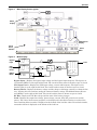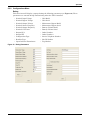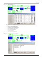
1
AC Power
For Business-Critical Continuity™
Liebert® NXL™
Operation and Maintenance Manual – 250-400kVA, 60Hz, Three Phase Single-Module
BATTERY CABINET PRECAUTIONS
The following warning applies to all battery cabinets supplied with UPS systems. Additional warnings and cautions applicable to battery cabinets may be found in Important Safety Instructions and
3.4 - Battery Maintenance.
! WARNING
Internal battery strapping must be verified by manufacturer prior to moving a battery cabinet
(after initial installation).
• Battery cabinets contain non-spillable batteries.
• Keep units upright.
• Do not stack.
• Do not tilt.
Failure to heed this warning could result in smoke, fire or electric hazard.
Call 1-800-LIEBERT before moving battery cabinets (after initial installation).
Contacting Liebert for Support
Contact Emerson Network Power Liebert Services for information or repair service in the United
States at 1-800-LIEBERT (1-800-543-2378).
For repair or maintenance service outside the 48 contiguous United States, contact Liebert Services,
if available in your area. For areas not covered by Liebert Services, the authorized distributor is
responsible for providing qualified, factory-authorized service.
Have the following information available before calling Liebert Services:
Part Numbers: ________________________________________________________________
Serial Numbers: _______________________________________________________________
kVA Rating: __________________________________________________________________
Date Purchased: _______________________________________________________________
Date Installed: ________________________________________________________________
Location: _____________________________________________________________________
Input Voltage/Frequency: ______________________________________________________
Output Voltage/Frequency: _____________________________________________________
Battery Reserve Time: _________________________________________________________
TABLE OF CONTENTS
BATTERY CABINET PRECAUTIONS . . . . . . . . . . . . . . . . . . . . . . . . . . . . . . . . . . . . . . . . . . . . . . . . .2
IMPORTANT SAFETY INSTRUCTIONS . . . . . . . . . . . . . . . . . . . . . . . . . . . . . . . . . . . . . . . . . .1
1.0
INTRODUCTION . . . . . . . . . . . . . . . . . . . . . . . . . . . . . . . . . . . . . . . . . . . . . . . . . . . . . . . . . .2
1.1
General Description . . . . . . . . . . . . . . . . . . . . . . . . . . . . . . . . . . . . . . . . . . . . . . . . . . . . . . . . . . 2
1.2
Modes of Operation. . . . . . . . . . . . . . . . . . . . . . . . . . . . . . . . . . . . . . . . . . . . . . . . . . . . . . . . . . . 2
1.2.1
1.2.2
1.2.3
1.2.4
Normal Mode . . . . . . . . . . . . . . . . . . . . . . . . . . . . . . . . . . . . . . . . . . . . . . . . . . . . . . . . . . . . . . . .
Bypass Mode . . . . . . . . . . . . . . . . . . . . . . . . . . . . . . . . . . . . . . . . . . . . . . . . . . . . . . . . . . . . . . . . .
Battery Mode . . . . . . . . . . . . . . . . . . . . . . . . . . . . . . . . . . . . . . . . . . . . . . . . . . . . . . . . . . . . . . . .
Maintenance Bypass. . . . . . . . . . . . . . . . . . . . . . . . . . . . . . . . . . . . . . . . . . . . . . . . . . . . . . . . . . .
2
3
3
3
1.3
Options . . . . . . . . . . . . . . . . . . . . . . . . . . . . . . . . . . . . . . . . . . . . . . . . . . . . . . . . . . . . . . . . . . . . 3
2.0
OPERATION . . . . . . . . . . . . . . . . . . . . . . . . . . . . . . . . . . . . . . . . . . . . . . . . . . . . . . . . . . . .5
2.1
Features . . . . . . . . . . . . . . . . . . . . . . . . . . . . . . . . . . . . . . . . . . . . . . . . . . . . . . . . . . . . . . . . . . . 5
2.2
Touchscreen Navigation. . . . . . . . . . . . . . . . . . . . . . . . . . . . . . . . . . . . . . . . . . . . . . . . . . . . . . . 9
2.2.1
2.2.2
2.2.3
2.2.4
2.2.5
2.2.6
2.2.7
2.2.8
2.2.9
2.2.10
2.2.11
2.3
Modes of Operation. . . . . . . . . . . . . . . . . . . . . . . . . . . . . . . . . . . . . . . . . . . . . . . . . . . . . . . . . . 19
2.3.1
2.3.2
2.3.3
2.3.4
2.3.5
2.3.6
2.4
19
20
21
22
22
23
Startup Procedure . . . . . . . . . . . . . . . . . . . . . . . . . . . . . . . . . . . . . . . . . . . . . . . . . . . . . . . . . . . 24
Load Transfer Procedures . . . . . . . . . . . . . . . . . . . . . . . . . . . . . . . . . . . . . . . . . . . . . . . . . . . . . 26
Maintenance Bypass Load Transfers . . . . . . . . . . . . . . . . . . . . . . . . . . . . . . . . . . . . . . . . . . . . 26
Shutdown Procedures. . . . . . . . . . . . . . . . . . . . . . . . . . . . . . . . . . . . . . . . . . . . . . . . . . . . . . . . 28
2.5.1
2.6
Load on Bypass . . . . . . . . . . . . . . . . . . . . . . . . . . . . . . . . . . . . . . . . . . . . . . . . . . . . . . . . . . . . . .
OK to Transfer . . . . . . . . . . . . . . . . . . . . . . . . . . . . . . . . . . . . . . . . . . . . . . . . . . . . . . . . . . . . . .
Input Power Failure—Load on Battery. . . . . . . . . . . . . . . . . . . . . . . . . . . . . . . . . . . . . . . . . . .
Off Battery . . . . . . . . . . . . . . . . . . . . . . . . . . . . . . . . . . . . . . . . . . . . . . . . . . . . . . . . . . . . . . . . .
Emergency Module Off . . . . . . . . . . . . . . . . . . . . . . . . . . . . . . . . . . . . . . . . . . . . . . . . . . . . . . . .
Remote Emergency Power Off . . . . . . . . . . . . . . . . . . . . . . . . . . . . . . . . . . . . . . . . . . . . . . . . . .
Manual Procedures. . . . . . . . . . . . . . . . . . . . . . . . . . . . . . . . . . . . . . . . . . . . . . . . . . . . . . . . . . 23
2.4.1
2.4.2
2.4.3
2.5
Main Display Screen . . . . . . . . . . . . . . . . . . . . . . . . . . . . . . . . . . . . . . . . . . . . . . . . . . . . . . . . . . 9
Configurations Menu . . . . . . . . . . . . . . . . . . . . . . . . . . . . . . . . . . . . . . . . . . . . . . . . . . . . . . . . . 10
Status Reports Menu . . . . . . . . . . . . . . . . . . . . . . . . . . . . . . . . . . . . . . . . . . . . . . . . . . . . . . . . . 14
Startup Menu . . . . . . . . . . . . . . . . . . . . . . . . . . . . . . . . . . . . . . . . . . . . . . . . . . . . . . . . . . . . . . . 14
Shutdown Menu . . . . . . . . . . . . . . . . . . . . . . . . . . . . . . . . . . . . . . . . . . . . . . . . . . . . . . . . . . . . . 15
Transfer Menu . . . . . . . . . . . . . . . . . . . . . . . . . . . . . . . . . . . . . . . . . . . . . . . . . . . . . . . . . . . . . . 16
Battery Management Menu . . . . . . . . . . . . . . . . . . . . . . . . . . . . . . . . . . . . . . . . . . . . . . . . . . . . 17
Metering . . . . . . . . . . . . . . . . . . . . . . . . . . . . . . . . . . . . . . . . . . . . . . . . . . . . . . . . . . . . . . . . . . . 19
Help . . . . . . . . . . . . . . . . . . . . . . . . . . . . . . . . . . . . . . . . . . . . . . . . . . . . . . . . . . . . . . . . . . . . . . . 19
Reset . . . . . . . . . . . . . . . . . . . . . . . . . . . . . . . . . . . . . . . . . . . . . . . . . . . . . . . . . . . . . . . . . . . . . . 19
Silence . . . . . . . . . . . . . . . . . . . . . . . . . . . . . . . . . . . . . . . . . . . . . . . . . . . . . . . . . . . . . . . . . . . . . 19
Module Shutdown Procedure . . . . . . . . . . . . . . . . . . . . . . . . . . . . . . . . . . . . . . . . . . . . . . . . . . . 28
Automatic Operations . . . . . . . . . . . . . . . . . . . . . . . . . . . . . . . . . . . . . . . . . . . . . . . . . . . . . . . 28
2.6.1
2.6.2
2.6.3
2.6.4
Overloads (Without Transfer) . . . . . . . . . . . . . . . . . . . . . . . . . . . . . . . . . . . . . . . . . . . . . . . . . .
Automatic Transfers to Bypass (Overload Condition) . . . . . . . . . . . . . . . . . . . . . . . . . . . . . . .
Automatic Transfers to Bypass, UPS System Faults . . . . . . . . . . . . . . . . . . . . . . . . . . . . . . . .
Automatic Retransfers to UPS. . . . . . . . . . . . . . . . . . . . . . . . . . . . . . . . . . . . . . . . . . . . . . . . . .
28
29
30
30
3.0
MAINTENANCE . . . . . . . . . . . . . . . . . . . . . . . . . . . . . . . . . . . . . . . . . . . . . . . . . . . . . . . . . 31
3.1
Safety Precautions . . . . . . . . . . . . . . . . . . . . . . . . . . . . . . . . . . . . . . . . . . . . . . . . . . . . . . . . . . 31
i
3.2
Liebert Services . . . . . . . . . . . . . . . . . . . . . . . . . . . . . . . . . . . . . . . . . . . . . . . . . . . . . . . . . . . . 32
3.2.1
3.3
Routine Maintenance . . . . . . . . . . . . . . . . . . . . . . . . . . . . . . . . . . . . . . . . . . . . . . . . . . . . . . . . 32
3.3.1
3.3.2
3.3.3
3.4
Professional Startup . . . . . . . . . . . . . . . . . . . . . . . . . . . . . . . . . . . . . . . . . . . . . . . . . . . . . . . . . . 32
Record Log. . . . . . . . . . . . . . . . . . . . . . . . . . . . . . . . . . . . . . . . . . . . . . . . . . . . . . . . . . . . . . . . . . 33
Air Filters . . . . . . . . . . . . . . . . . . . . . . . . . . . . . . . . . . . . . . . . . . . . . . . . . . . . . . . . . . . . . . . . . . 33
Limited Life Components. . . . . . . . . . . . . . . . . . . . . . . . . . . . . . . . . . . . . . . . . . . . . . . . . . . . . . 34
Battery Maintenance . . . . . . . . . . . . . . . . . . . . . . . . . . . . . . . . . . . . . . . . . . . . . . . . . . . . . . . . 34
3.4.1
3.4.2
Battery Safety Precautions . . . . . . . . . . . . . . . . . . . . . . . . . . . . . . . . . . . . . . . . . . . . . . . . . . . . 35
Torque Requirements . . . . . . . . . . . . . . . . . . . . . . . . . . . . . . . . . . . . . . . . . . . . . . . . . . . . . . . . . 37
3.5
Detecting Trouble . . . . . . . . . . . . . . . . . . . . . . . . . . . . . . . . . . . . . . . . . . . . . . . . . . . . . . . . . . . 37
3.6
Reporting a Problem. . . . . . . . . . . . . . . . . . . . . . . . . . . . . . . . . . . . . . . . . . . . . . . . . . . . . . . . . 38
3.7
Corrective Actions . . . . . . . . . . . . . . . . . . . . . . . . . . . . . . . . . . . . . . . . . . . . . . . . . . . . . . . . . . 38
3.8
Upstream Feeder Circuit Breaker Setting Inspections . . . . . . . . . . . . . . . . . . . . . . . . . . . . . 38
4.0
SPECIFICATIONS . . . . . . . . . . . . . . . . . . . . . . . . . . . . . . . . . . . . . . . . . . . . . . . . . . . . . 39
4.1
Battery Operation. . . . . . . . . . . . . . . . . . . . . . . . . . . . . . . . . . . . . . . . . . . . . . . . . . . . . . . . . . . 39
4.2
Environmental Conditions . . . . . . . . . . . . . . . . . . . . . . . . . . . . . . . . . . . . . . . . . . . . . . . . . . . . 39
APPENDIX A - UPS ALARM AND STATUS MESSAGES . . . . . . . . . . . . . . . . . . . . . . . . . . . . . . . . A43
ii
FIGURES
Figure 1
Figure 2
Figure 3
Figure 4
Figure 5
Figure 6
Figure 7
Figure 8
Figure 9
Figure 10
Figure 11
Figure 12
Figure 13
Figure 14
Figure 15
Figure 16
Figure 17
Figure 18
Figure 19
Figure 20
Figure 21
Figure 22
Figure 23
Figure 24
Figure 25
Figure 26
Figure 27
Figure 28
Figure 29
Figure 30
Figure 31
Figure 32
Typical UPS system one-line diagram . . . . . . . . . . . . . . . . . . . . . . . . . . . . . . . . . . . . . . . . . . . . . . . . 2
Main component locations . . . . . . . . . . . . . . . . . . . . . . . . . . . . . . . . . . . . . . . . . . . . . . . . . . . . . . . . . 5
Main Display Screen, typical . . . . . . . . . . . . . . . . . . . . . . . . . . . . . . . . . . . . . . . . . . . . . . . . . . . . . . . 6
Mimic display . . . . . . . . . . . . . . . . . . . . . . . . . . . . . . . . . . . . . . . . . . . . . . . . . . . . . . . . . . . . . . . . . . . 6
Monitor/mimic display example: Normal power flow . . . . . . . . . . . . . . . . . . . . . . . . . . . . . . . . . . . . 7
Monitor/mimic display example: Utility fail . . . . . . . . . . . . . . . . . . . . . . . . . . . . . . . . . . . . . . . . . . . 7
Monitor/mimic display example: Load on bypass, UPS On . . . . . . . . . . . . . . . . . . . . . . . . . . . . . . . 8
Monitor/mimic display example: Load on bypass, UPS module off . . . . . . . . . . . . . . . . . . . . . . . . . 8
Menu tree . . . . . . . . . . . . . . . . . . . . . . . . . . . . . . . . . . . . . . . . . . . . . . . . . . . . . . . . . . . . . . . . . . . . . . 9
Rating Parameters . . . . . . . . . . . . . . . . . . . . . . . . . . . . . . . . . . . . . . . . . . . . . . . . . . . . . . . . . . . . . . 10
System Settings parameters . . . . . . . . . . . . . . . . . . . . . . . . . . . . . . . . . . . . . . . . . . . . . . . . . . . . . . 11
Adjustable setpoints parameters . . . . . . . . . . . . . . . . . . . . . . . . . . . . . . . . . . . . . . . . . . . . . . . . . . . 12
Battery Management Parameters . . . . . . . . . . . . . . . . . . . . . . . . . . . . . . . . . . . . . . . . . . . . . . . . . . 13
Typical Event Management Parameters . . . . . . . . . . . . . . . . . . . . . . . . . . . . . . . . . . . . . . . . . . . . . 14
Shutdown menu . . . . . . . . . . . . . . . . . . . . . . . . . . . . . . . . . . . . . . . . . . . . . . . . . . . . . . . . . . . . . . . . 15
UPS shutdown popup . . . . . . . . . . . . . . . . . . . . . . . . . . . . . . . . . . . . . . . . . . . . . . . . . . . . . . . . . . . . 15
System shutdown popup . . . . . . . . . . . . . . . . . . . . . . . . . . . . . . . . . . . . . . . . . . . . . . . . . . . . . . . . . . 15
Transfer/retransfer commands. . . . . . . . . . . . . . . . . . . . . . . . . . . . . . . . . . . . . . . . . . . . . . . . . . . . . 16
Time remaining display . . . . . . . . . . . . . . . . . . . . . . . . . . . . . . . . . . . . . . . . . . . . . . . . . . . . . . . . . . 17
Battery cycle monitor . . . . . . . . . . . . . . . . . . . . . . . . . . . . . . . . . . . . . . . . . . . . . . . . . . . . . . . . . . . . 18
Battery cycle monitor summary . . . . . . . . . . . . . . . . . . . . . . . . . . . . . . . . . . . . . . . . . . . . . . . . . . . . 18
Battery cycle monitor—clear log . . . . . . . . . . . . . . . . . . . . . . . . . . . . . . . . . . . . . . . . . . . . . . . . . . . 19
Load on bypass (UPS not available). . . . . . . . . . . . . . . . . . . . . . . . . . . . . . . . . . . . . . . . . . . . . . . . . 19
Load on bypass, UPS available . . . . . . . . . . . . . . . . . . . . . . . . . . . . . . . . . . . . . . . . . . . . . . . . . . . . 20
Load on UPS, bypass available . . . . . . . . . . . . . . . . . . . . . . . . . . . . . . . . . . . . . . . . . . . . . . . . . . . . 20
Input power fail, load on battery . . . . . . . . . . . . . . . . . . . . . . . . . . . . . . . . . . . . . . . . . . . . . . . . . . . 21
Load on UPS, battery not available . . . . . . . . . . . . . . . . . . . . . . . . . . . . . . . . . . . . . . . . . . . . . . . . . 22
Emergency modules off . . . . . . . . . . . . . . . . . . . . . . . . . . . . . . . . . . . . . . . . . . . . . . . . . . . . . . . . . . . 22
Remote emergency power off . . . . . . . . . . . . . . . . . . . . . . . . . . . . . . . . . . . . . . . . . . . . . . . . . . . . . . 23
Startup commands . . . . . . . . . . . . . . . . . . . . . . . . . . . . . . . . . . . . . . . . . . . . . . . . . . . . . . . . . . . . . . 25
UPS with two-breaker bypass cabinet . . . . . . . . . . . . . . . . . . . . . . . . . . . . . . . . . . . . . . . . . . . . . . . 26
Current-versus-time curves of overload capacity . . . . . . . . . . . . . . . . . . . . . . . . . . . . . . . . . . . . . . 29
TABLES
Table 1
Table 2
Table 3
Table 4
Table 5
Table 6
Table 7
UPS component service life . . . . . . . . . . . . . . . . . . . . . . . . . . . . . . . . . . . . . . . . . . . . . . . . . . . . . . .
Battery voltage, nominal and float . . . . . . . . . . . . . . . . . . . . . . . . . . . . . . . . . . . . . . . . . . . . . . . . .
Battery retorque values . . . . . . . . . . . . . . . . . . . . . . . . . . . . . . . . . . . . . . . . . . . . . . . . . . . . . . . . . .
Torque specifications, unless otherwise labeled . . . . . . . . . . . . . . . . . . . . . . . . . . . . . . . . . . . . . . .
Environmental specifications . . . . . . . . . . . . . . . . . . . . . . . . . . . . . . . . . . . . . . . . . . . . . . . . . . . . . .
Electrical specifications . . . . . . . . . . . . . . . . . . . . . . . . . . . . . . . . . . . . . . . . . . . . . . . . . . . . . . . . . .
Liebert NXL alarm and status messages . . . . . . . . . . . . . . . . . . . . . . . . . . . . . . . . . . . . . . . . . . . .
iii
34
36
36
37
39
40
43
iv
IMPORTANT SAFETY INSTRUCTIONS
SAVE THESE INSTRUCTIONS
This manual contains important instructions that should be followed during installation and maintenance of your Liebert NXL UPS and batteries.
! WARNING
Risk of electric shock. Can cause equipment damage, injury or death.
Exercise extreme care when handling UPS cabinets to avoid equipment damage or injury to
personnel. Refer to separate installation manual for equipment handling information and
installation procedures.
Follow all battery safety precautions in 3.0 - Maintenance when installing, charging or
servicing batteries. In addition to the hazard of electric shock, gas produced by batteries can
be explosive and sulfuric acid can cause severe burns.
In case of fire involving electrical equipment, use only carbon dioxide fire extinguishers or
others approved for use in electrical fire fighting.
Extreme caution is required when performing maintenance. Service and maintenance work
must be performed only by properly trained and qualified personnel and in accordance with
applicable regulations as well as with manufacturers’ specifications.
Be constantly aware that the UPS system contains high DC as well as AC voltages. With
input power off and the battery disconnected, high voltage at filter capacitors and power
circuits should be discharged within 30 seconds. However, if a power circuit failure has
occurred, assume that high voltage still exists after shutdown. Check with a voltmeter before
making contact.
AC voltage will remain on the system bypass, the UPS output terminals and the static bypass
switch, unless associated external circuit breakers are opened.
Check for voltage with both AC and DC voltmeters prior to making contact.
When the UPS system is under power, both the operator and any test equipment must be
isolated from direct contact with earth ground and the UPS chassis frame by using rubber
mats.
Some components within the cabinets are not connected to the chassis ground. Any contact
between floating circuits and the chassis is a lethal shock hazard. Exercise caution that the
test instrument exterior does not make contact, either physically or electrically, with earth
ground.
This equipment contains circuitry that is energized with high voltage. Only test equipment
designated for troubleshooting should be used. This is particularly true for oscilloscopes. Always
check with an AC and DC voltmeter to ensure safety before making contact or using tools. Even when
the power is turned Off, dangerously high voltage may exist at the capacitor banks.
Observe all battery precautions when near the battery for any reason.
ONLY properly trained and qualified service personnel should perform maintenance on
the UPS system. When performing maintenance on any part of the equipment under power, service
personnel and test equipment should be standing on rubber mats. The service personnel should wear
insulating shoes for isolation from direct contact with the floor (earth ground).
One person should never work alone. A second person should be standing by to assist and summon
help in case an accident should occur. This is particularly true when work is performed on the battery.
1
Introduction
1.0
INTRODUCTION
1.1
General Description
The Liebert NXL UPS provides continuous, high-quality AC power to your business-critical equipment, such as telecommunications and data processing equipment. The Liebert NXL UPS supplies
power that is free of the disturbances and variations in voltage and frequency common to utility
power, which is subject to brownouts, blackouts, surges and sags.
The Liebert NXL utilizes the latest in high-frequency, double-conversion pulse-width modulation
technology and fully digital controls to enhance its reliability and increase the ease of use.
As shown in Figure 1, the AC utility source is input at CB1 and the rectifier converts the AC utility
into DC power. The inverter converts that DC power from the utility—or DC power from the batteries— into AC power for the load. The batteries power the load through the inverter in the event of a
power failure. The utility source can also power the load through the static bypass.
If maintenance or repair of the UPS is necessary, the load can be switched without interruption in
service to the maintenance bypass.
Figure 1
Typical UPS system one-line diagram
Bypass
BFB
Input
DC Bus
CB1
Battery
System
1.2
Modes of Operation
1.2.1
Normal Mode
CB2
Module
Output
MBD
Operating in normal mode, the Liebert NXL’s rectifier derives power from a utility AC source and
supplies regulated DC power to the inverter, which regenerates precise AC power to supply the connected equipment. The rectifier also uses the utility source power to charge the batteries.
2
Introduction
1.2.2
Bypass Mode
When the Liebert NXL is in bypass mode, the load is directly supported by utility power and is without battery backup protection.
The Liebert NXL’s inverter and bypass static switch will shift the load from the inverter to bypass
mode without an interruption in AC power if the inverter is synchronous with the bypass and any of
the following occurs:
• Inverter fails
• Inverter overload capacity is exceeded
• Inverter is manually turned off by the user
NOTE
If the inverter is asynchronous with the bypass, the static switch will transfer the load from the
inverter to the bypass WITH interruption in AC power to the critical load. This interruption
will be less than 10ms. This interruption time may be altered by modifying the Output transfer
interrupt time setting.
1.2.3
Battery Mode
When utility AC power fails, the Liebert NXL protects the critical load by instantaneously channeling
battery power to the inverter, which continues supporting the critical load without interruption.
When utility power returns and is within acceptable limits, the Liebert NXL automatically shifts back
to Normal mode, with the rectifier powering the critical load.
1.2.4
Maintenance Bypass
The installation of a Maintenance Bypass Cabinet or Assembly is recommended to allow you to totally
isolate the UPS from all power sources. Use of the Maintenance Bypass is described in 2.0 - Operation.
1.3
Options
A number of options are available from Liebert for your UPS system. (Some options are not available
for all ratings.) Described below are the most frequently provided options. The first three battery
items are required to complete the UPS system. The remaining options provide improved system performance or convenience. Other options are available. Contact your Liebert sales representative for more information.
• Battery and Racks—The batteries provide power in the event of a power outage. The Liebert
NXL UPS can use a variety of battery types, provided the battery plant is designed for the UPS
DC voltage range and the load requirements of your application. This option is required to complete the UPS system.
• Battery Cabinets—Valve-regulated, lead-acid (VRLA) sealed batteries are available in matching cabinets for convenient installation and maintenance in otherwise unprotected space.
Depending on the UPS module rating, two or more cabinets may be connected in parallel to provide the additional run time. This option is required to complete the UPS system.
• Module Battery Disconnect—The UPS system utilizes a separate Module Battery Disconnect
for remotely located batteries. A sensing circuit in the UPS module, set at the battery low voltage
limit, trips the Module Battery Disconnect to safeguard the battery from excessive discharge. The
Module Battery Disconnect has an undervoltage release mechanism designed to ensure that during any shutdown or failure mode all battery potential is removed from the UPS system. This
option is required to complete the UPS system.
• Input Current Distortion Filter—This filter reduces input current reflected harmonic distortion to less than 7% reflected THD at full load. The filter is factory-installed in the UPS. This filter also improves the input power factor to better than 0.92 lagging at full load.
• Two Breaker Maintenance Bypass—This switchboard provides make-before-break maintenance bypass. It includes: Maintenance Bypass Breaker (MBB) and Maintenance Isolation
Breaker (MIB).
3
Introduction
• Load Bus Synchronization—The Load Bus Sync (LBS) option keeps two independent UPS systems (and therefore their critical load buses) in sync, even when the modules are operating on batteries or asynchronous AC sources. This means that critical loads connected to both load buses
can switch seamlessly between the two.
• Customer Alarm Interface—This optional interface board allows the input and display of eight
alarms from customer-supplied contacts, each with a customer-selected name of up to 19 characters. The following attributes can be programmed for each alarm: latching, audible, event log and
time delay (0 to 99.9 seconds).
• Temperature-Compensated Charging—When the battery temperature exceeds a preset limit
(typically 77°F [25°C]), this optional circuit proportionally reduces float charging voltage to prevent overcharging the battery.
• Battery Load Testing—When activated, this option forces the battery string to assume the load
for a short period of time. The UPS then compares the test results to data collected during the
UPS commissioning to see if the battery system appears to meet specifications.
The Liebert NXL will display status events for Battery Equalize, Battery Self-Test and Battery Commissioning when those options are active.
4
Operation
2.0
OPERATION
The Liebert NXL UPS is equipped with a microprocessor-based display touchscreen designed for convenient and reliable operation. The display is driven by an easy-to- follow, menu-prompted software.
2.1
Features
The Liebert NXL interface display enables the operator to perform such tasks as:
•
•
•
•
•
•
Quickly check operational status
Monitor the power flow through the UPS system and all meter readings
Execute operational procedures
Check status reports and history files
Adjustment programmable parameters (access limited by security access function)
Adjustment output voltage before performing a manual load transfer.
The touchscreen is a white-background display with multicolor text. The display turns on automatically, but after 15 minutes of inactivity the backlight will go out and the display will appear very dim.
Touching the screen will reactivate the backlight; the backlight will again be active for 15 minutes. If
any screen other than the mimic screen is accessed, that screen will be displayed for 5 minutes without any interaction. If there is no activity for 5 minutes, the display will revert to the basic mimic
screen.
Figure 2
Main component locations
EXTERNAL
INTERFACE
BOARD
(CB2)
5
(CB1)
Operation
Figure 3
Main Display Screen, typical
Mimic
Display
Multipurpose
Display
Active
Event
Window
Menu
Bar
Figure 4
Mimic display
Bypass
Input
L-L
Freq
BYPASS
A
B
C
0
0
0
0.0Hz
L-L
I
Freq
INPUT
A
B
0
0
0
0
0.0Hz
UPS
Input
Power
Battery
Block
C
0
0
V
BFB
DC BUS
V
A
Voltage
Current
CB1
T
BATTERY 1 OF 4
Voltage Disable
Temp Disable
BIS1
0V
Float
CB2
MODULE OUTPUT
A
B
C
L-L
0
0
0 V
L-N
0
0
0 V
I
0
0
0 A
KVA 0
0
0 %
KW
0
0
0 %
PF
0.0 0.0 0.0
KVA/KW
0/
0
Freq
0.0Hz
Rexfer Timeout
00:00
Load
Legend
Inlet Air Temp 0°C
MBD
Bypass Input—Displays the bypass input voltage and the bypass input frequency. The bypass circuit breaker (BFB) is to the right of this block. The circuit breaker status is shown as open or closed.
UPS Input Power—Displays the UPS input voltage, current and frequency. The input circuit
breaker (CB1) is to the right of this block. The circuit breaker status is shown as open or closed.
Battery Block—Displays the battery voltage and the charge or discharge current to or from the battery. Pressing this icon switches among the connected battery strings. The Module Battery Disconnect (MBD) is to the right of this block. The circuit breaker status is shown as open or closed.
DC Bus—Displays the DC Bus voltage and the state of the battery charger.
Load—Displays the output line voltage, phase voltage, current, kVA, kW, power factor and frequency. The critical load current per phase is also displayed in this block. During an overload, the
time remaining before transfer is displayed at the bottom of the load box. After an overload transfer,
retransfer timeout is displayed at the bottom of the load box.
6
Operation
Figure 5
Monitor/mimic display example: Normal power flow
Green – Normal
Orange – Marginal
Gray – Absent
Black – Unknown
Figure 6
Monitor/mimic display example: Utility fail
Green – Normal
Orange – Marginal
Gray – Absent
Black – Unknown
7
Operation
Figure 7
Monitor/mimic display example: Load on bypass, UPS On
Green – Normal
Orange – Marginal
Gray – Absent
Black – Unknown
Figure 8
Monitor/mimic display example: Load on bypass, UPS module off
Green – Normal
Orange – Marginal
Gray – Absent
Black – Unknown
8
Operation
2.2
Touchscreen Navigation
2.2.1
Main Display Screen
Several menu items can be accessed from the main display screen (see Figure 3). These menu items
are detailed in subsequent sections.
Figure 9
Menu tree
Liebert NXL Menu
Configurations
Status Reports
Startup
Shutdown
Transfer
Battery
Management
Metering
Rating
Event Log
Manual Start
Open Trap
UPS
Time Remaining
Graph
Silence
System Settings
System Status
Device Control
Open MBD
Bypass
Manual Battery
Test
Reset
Adjustable
Setpoints
UPS
Manual Battery
Equalize
Battery
Management
System
Commissioning
Help Menu
Event
Management
Battery Cycle
Monitoring
Internal Option
Settings
9
Operation
2.2.2
Configurations Menu
Rating
This menu item will display a popup showing the following parameters (see Figure 10). These
parameters are entered during commissioning when the UPS is installed.
• Nominal Input Voltage
• Unit Model
• Nominal Bypass Voltage
• Unit Serial
• Nominal Output Voltage
• Maintenance Bypass Model
• Nominal Source Frequency
• Maintenance Bypass Serial
• Nominal Output Frequency
• Battery Cabinet Model
• Nominal Cell Count
• Battery Cabinet Serial
• Output kVA
• Order Number 1
• Output KW
• Order Number 2
• Configuration Type
• Service Telephone Number
• Rectifier Type
• Site ID Number
• Input Isolation Transformer
• Tag Number
Figure 10 Rating Parameters
10
Operation
User Settings
System Settings
These display settings can be changed from the touchscreen. Press the box to the left of each parameter to bring a popup window that will allow the parameter to be changed.
•
•
•
•
•
•
•
•
Figure 11
Backlight Brightness—High or Low (default: Low)
Time (24hr format)—Adjust Hour, Minute or Seconds
Date (MM DD, YYYY format)—Adjust Month, Day or Year
Password – Reset the password (4 characters, alphanumeric, case-sensitive)
Language—English, Chinese, French, Spanish, German, Italian, Portuguese
Audio level—Range 1 to 10 (default: 5)
Phase labeling—Auto, ABC, RST, XYZ, RYB, RWB, UVW, 123, L1L2L3 (default: Automatic)
Unit Locator
• Location ID—Alphanumeric
• System Number—Alphanumeric
• Unit Number—Number (1 through 99)
• Unit Label—Alphanumeric
System Settings parameters
11
Operation
Adjustable Setpoints
These warning and alarm settings can be changed from the touchscreen. Press the box to the left of
each parameter to bring a popup window that will allow the parameter to be changed.
Max Load Alarm
•
•
•
•
Phase A (%)—10% to 105% (default: 95%)
Phase B (%)—10% to 105% (default: 95%)
Phase C (%)—10% to 105% (default: 95%)
Delay (second)—0 to 60 (default: 5 seconds)
Manual Xfer Bypass Voltage Limits
• Manual Xfer Bypass Voltage Low Limit (%)—1% to 20% (default: 5%)
• Manual Xfer Bypass Voltage High Limit (%)—1% to 15% (default: 5%)
Inlet Air Temp Warning
• Inlet Air Temp Warning—30°C to 40°C (default: 35°C)
NOTE
Temperature will display in both Celsius and Fahrenheit.
Figure 12 Adjustable setpoints parameters
Battery Management
These battery settings can be changed from the touchscreen. Press the box to the left of each parameter to bring a popup window that will allow the parameter to be changed.
Battery Equalize:
• Equalize Voltage, Vpc - 2.30 to 2.40 (default: 2.3)
• Equalize Time, hours - 0 to 200hours (default: 0)
NOTE
Battery Equalize must be enabled by service to be functional. If Battery Equalize is disabled,
the feature will not be available and the menu item will not be displayed.
12
Operation
Battery Test
•
•
•
•
•
Auto Test—Enable/Disable (default: disabled)
Test Cycle, weeks—1 to 26 (default: 13 weeks)
Time of day, hh:mm—Set Hour and Minute; sets the start time of the automatic battery test
Start Date, mm dd, yyyyy—Set Month, Day and Year
Test Duration, minutes—Automatic, 0.5 minute to 30% of full load Operating Time
(default: automatic)
• Minimum Battery Voltage, lead-acid only—1.75VPC to 1.95VPC (default: 1.75VPC); this is the
minimum voltage the battery test will stop.
Low Battery Warning Time
• Low Battery Warning Time, minutes—2 to 60, depending on configured batteries (default: 5 minutes)
Battery Temperature
• Battery Temp Warning—30°C to 50°C (default: 40°C)
• Battery Temp Limit—35°C to 60°C (default: 50°C)
• Disconnect—Enable/Disable (default: disabled)
NOTE
If Disconnect is set to “Enable’ and the Battery Temp Limit is met, the Battery breaker will
open.
Figure 13 Battery Management Parameters
Cell Count Adjustment
• Cell Count Adjustment— -12 cells to +6 cells (default: 0)
Float Voltage
• Battery Float Voltage, Vpc—2.15 to 2.3 (default: 2.25)
13
Operation
Event Management
This menu item permits changing how the Liebert NXL handles Alarms, Faults and Status information. Each event can be configured for the following:
• Latch (yes/no)—Event stays active in the event window, even if the fault condition has been
cleared, until user acknowledges it by pressing the “Reset” button.
• Audible (yes/no)—Will set Audible alarm when event occurs
• Event log (yes/no)—Will display event in Event log when it occurs
NOTE
You must press “Save” for changes to take effect.
See Table 7 for a list of alarms, fault and status messages.
Figure 14 Typical Event Management Parameters
2.2.3
Status Reports Menu
This menu accesses the events records.
• Event Log—Up to 1024 time/date stamped events are captured in the log. The oldest record will
be overwritten with a new record once the buffer reaches 1024 events.
• System Status
• Total Operating Hours—Total number hours the UPS has been operational
• Battery Operating Time—A running total of the battery discharge time for all events since
the log was last cleared
2.2.4
Startup Menu
This menu is used to start the UPS and individual devices.
Manual—This will begin the UPS startup. See 2.4 - Manual Procedures for details.
Devices
• Close Trap—This will start the Input filter, if installed
• Close MBD/BCB—If MBD is motor operated, the Close command will Enable and energize the
motor to close. If MBD is not motorized, the Close command will Enable the breaker UVR. The
MBD/BCB must be closed manually. If no MBD is selected, do not display this setting.
14
Operation
2.2.5
Shutdown Menu
This menu permits shutting down the UPS and individual devices.
Figure 15 Shutdown menu
Open Trap—Open the input trap filter
Open MBD/BCB—Opens the associated MBD or BCB breaker
UPS—Turns off inverter, rectifier and trips all battery breakers. Transfers to bypass, if available.
NOTE
The following popup window is displayed when the UPS is about to be shut down. To shut
down the UPS, an operator must press OK.
Figure 16 UPS shutdown popup
System—Turns off inverter, rectifier and trips all battery breakers. Will shutdown UPS completely.
NOTICE
Risk of equipment damage. This command will result in the load being shut down.
The following popup window is displayed when the UPS is about to be shut down. To shutdown the
UPS, an operator must press OK.
Figure 17 System shutdown popup
15
Operation
2.2.6
Transfer Menu
This menu permits switching between UPS and Bypass mode. A graph in the multipurpose window
shows if the UPS is in synch with the bypass. If the UPS and bypass are in synch, pressing Bypass
will switch the UPS to Bypass mode. Pressing UPS will switch back to Normal (Inverter) Mode (see
Figure 18).
Figure 18 Transfer/retransfer commands
16
Operation
2.2.7
Battery Management Menu
This menu permits configuring battery settings.
Time Remaining Graph—Displays the time remaining graph in the multipurpose window; plot the
battery voltage against elapsed time during a Battery Discharge Cycle (see Figure 19).
Figure 19 Time remaining display
Manual Battery Test—Start/Stop
Manual Battery Equalize—For Service only.
Commissioning—For Service only.
Battery Cycle Monitor—Displays how many discharges have occurred for these time periods:
0-30sec, 31-90sec, 91-240sec, 4-15min, 15-30min, 30-60min, 60-240min, 4-8hrs, 8hrs and up. Each
discharge record will include: (see Figure 20)
• #
• Max KW
• Date
• AH
• Time
• Start Temp °C
• Duration
• End Temp °C
• Start KW
• Battery CB Start
• Min KW
• Battery CB End
17
Operation
Figure 20 Battery cycle monitor
Display summary (see Figure 21)
•
•
•
•
•
•
Battery Commission Date/Time
Last Battery Discharge Date/Time
Active Battery Discharge Time
Active Battery Amp Hours
Active Battery KW
Total Number of Discharges
Figure 21 Battery cycle monitor summary
18
Operation
Clear Log—This command resets the Date of First Discharge Cycle. A dialog box will warn that the
data will be permanently lost and should downloaded before proceeding (see Figure 22).
Figure 22 Battery cycle monitor—clear log
2.2.8
Metering
This button will place the metering tables in the multipurpose window.
2.2.9
Help
This button will display the help menu.
2.2.10 Reset
This button will reset any non-active latched events.
2.2.11 Silence
This button will silence the audible alarm.
2.3
Modes of Operation
This section illustrates the flow of power through circuit breakers, switches and UPS components
during various modes of operation. The same modes of operation apply to all configurations of the Liebert NXL. Highlighted (thick) lines in the diagrams indicate power flow and power availability.
These illustrations do not show an alternate power source (generator) and automatic transfer switch
(external to the UPS) that might be present at your installation.
2.3.1
Load on Bypass
Load on Bypass, with the UPS not available, is shown in Figure 23. The UPS system could be in this
mode of operation during either initial startup or UPS system shutdown and isolation for maintenance.
NOTICE
Risk of equipment damage. When the critical load is being supplied power from the bypass
line, it is exposed to utility failure and fluctuations.
Figure 23 Load on bypass (UPS not available)
Bypass
BFB
Input
DC Bus
CB1
Battery
System
MBD
19
CB2
Module
Output
Operation
2.3.2
OK to Transfer
The OK to Transfer status message will be displayed when the bypass line and UPS output power are
both available, their voltage, frequency and phase synchronization are matched within specifications,
and the Static Switch Disconnects are closed (ON). An alarm message may be displayed to indicate
Load On Bypass (Figure 24). If no alarm is displayed, the operating status is Load On UPS
(Figure 25).
When the OK to Transfer message is displayed, the load can be manually transferred from the UPS to
bypass or the load can be manually retransferred from the bypass to the UPS.
To perform a manual transfer, Use the Load Transfer Procedures screen. Refer to 2.4.2 - Load
Transfer Procedures.
The UPS control logic will initiate an automatic transfer to bypass if an overload condition exceeds
the system current versus time window or if a UPS fault is detected. The control logic may initiate an
automatic retransfer to the UPS system when the system is recovering from overloads lasting less
than five minutes. Refer to 2.6 - Automatic Operations.
Figure 24 Load on bypass, UPS available
Bypass
BFB
Input
DC Bus
CB1
Battery
System
CB2
Module
Output
CB2
Module
Output
MBD
Figure 25 Load on UPS, bypass available
Bypass
BFB
Input
DC Bus
CB1
Battery
System
MBD
20
Operation
2.3.3
Input Power Failure—Load on Battery
If the utility AC power source fails or is outside the acceptable range, the battery plant becomes the
power source for the UPS module inverters. The UPS continues to supply power to the critical load
and also to the UPS controls.
Use the Battery Time screen at the UPS modules to monitor the present battery voltage compared to
the shutdown value. The time the battery can sustain the load depends on the size of the load and the
size and condition of the battery plant.
Alarm messages that indicate battery status are Battery Discharge, Low Battery and Battery Shutdown. The voltage limits for these alarms are displayed on the UPS module Alarm Limit Settings
screen. These limits were selected for your installation by Liebert Services during initial startup. The
battery block in the UPS module Monitor/Mimic Display indicates Charge or Discharge and the current in amperes.
Figure 26 Input power fail, load on battery
Bypass
BFB
Input
DC Bus
CB1
Battery
System
MBD
21
CB2
Module
Output
Operation
2.3.4
Off Battery
The battery plant can be disconnected from the UPS, if required for battery maintenance, by opening
the module battery disconnect (MBD) circuit breaker. In this situation the UPS module will continue
to supply conditioned power to the critical load, but if input power fails the UPS system cannot supply
power to the load.
! CAUTION
When the UPS system is operating with the module battery disconnect (MBD) circuit
breaker(s) open, the critical load is not protected from loss of the utility source power.
Figure 27 Load on UPS, battery not available
Bypass
BFB
Input
DC Bus
CB1
Battery
System
2.3.5
CB2
Module
Output
MBD
Emergency Module Off
The Local Emergency Module Off (LEMO) mode will transfer the critical load to the bypass line and
remove power from all UPS module components except the controls, bypass circuit breaker and the
static switch.
The Emergency Module Off control is a guarded pad next to the display touchscreen (Figure 2).
Lift the cover and press the pad. The load will be transferred to bypass, and the battery (MBD), input
and output circuit breakers will be opened (tripped). Refer to 2.5 - Shutdown Procedures.
Figure 28 Emergency modules off
Bypass
BFB
Input
DC Bus
CB1
Battery
System
MBD
22
CB2
Module
Output
Operation
2.3.6
Remote Emergency Power Off
The Remote Emergency Power Off (REPO) mode will transfer the critical load to the bypass line and
remove power from all UPS module components except the controls, bypass circuit breaker and the
static switch.
The Remote Emergency Power Off control is a user-provided switch located remotely from the UPS
system. It usually is installed in the same room as the critical load equipment. This mode can also be
initiated by an automatic contact closure in the same external circuit as the manually operated
switch.
When the Remote Emergency Power Off switch is operated, all UPS circuit breakers are opened,
including the bypass circuit breaker. All power through the UPS is removed from the load. Typically,
the REPO circuit also opens the circuit breakers that provide power to the bypass lines and the UPS
controls. Refer to 2.5 - Shutdown Procedures.
Figure 29 Remote emergency power off
Bypass
BFB
Input
DC Bus
CB1
Battery
System
2.4
CB2
Module
Output
MBD
Manual Procedures
The Liebert NXL UPS is designed to function while unattended by an operator. Many important functions are handled automatically by the system control logic, as explained in 2.6 - Automatic Operations. Other procedures must be performed manually.
Manual procedures available to the operator include Startup, Load Transfers and Shutdowns. These
procedures are performed by using the touchscreen and some manually operated circuit breakers and
switches.
The touchscreen lists all steps required for each manual procedure. This section lists step-by-step controls to operate and conditions to observe in the following manual procedures:
• Startup—including initial startup, recovering from input power failure, recovering from battery
shutdown and recovering from shutdowns for emergencies or maintenance.
• Load Transfers—including transfers from UPS to bypass and retransfers from bypass to the
UPS system.
• Maintenance Bypass Load Transfers—including transferring from internal bypass to maintenance bypass and transferring from maintenance bypass to internal bypass.
• Shutdowns—including module shutdowns for maintenance and emergency shutdowns.
NOTE
The following procedure assumes that the UPS installation inspection and initial startup have
been performed by Liebert Services. A Liebert-authorized representative must perform the
initial system startup to ensure proper system operation.
23
Operation
2.4.1
Startup Procedure
! CAUTION
The following procedure provides power to the critical load distribution system. Verify that
the critical load distribution is ready to accept power. Make sure that personnel and
equipment are ready for the critical load distribution system to be energized.
If your installation includes a Maintenance Bypass, you may already be supplying power to the critical load equipment through the Maintenance Bypass. If there is no power to the critical load, apply
power through the UPS bypass line per the following procedure.
During startup, power is supplied to the critical load through the UPS (internal) bypass line while the
UPS system is being energized. Depending on the reason for the UPS system shutdown, power may
be present in the bypass line. To determine this, check the Monitor/Mimic Display screen after control
power is available.
1. Before you apply power to the UPS modules, determine the position of the following circuit
breakers and switches:
• Input Circuit Breaker (CB1)—Verify that this breaker on the front of the UPS cabinet
(Figure 2) is in the Open position.
• Module Battery Disconnect (MBD)—Verify that this external breaker is open or tripped. If
battery cabinets are used, verify that breakers on all the cabinets are open.
• Bypass Circuit Breaker (BFB)—This circuit breaker (Figure 2) should be open.
NOTE
Power to the critical load may already be supplied through this breaker.
• Output Circuit Breaker (CB2)—This motorized circuit breaker (Figure 2) should be open.
NOTE
If the system was shut down in response to an “Emergency Off”, there may be alarm messages
on the touchscreen that describe system conditions before (or at the time of) the shutdown.
Some or all of the alarm conditions may have been resolved. To clear these alarm messages,
turn off control power (see Figure 2). Wait at least 10 minutes for the control power circuitry to
completely de-energize. After 10 minutes, turn control power back on and wait two minutes
before continuing.
! WARNING
Risk of electrical shock and high short circuit current. Can cause equipment damage, personal
injury and death.
If the UPS has been shut down for maintenance, verify that all of the UPS system doors are
closed and latched. All test equipment must be removed from the system. All electrical
connections must be secure.
2. Power must be provided to the UPS controls so the operator can use the display touchscreen and
so the system logic can function properly. The display touchscreen may be used to monitor UPS
system status, even when the UPS modules are not operating. This will be the usual condition
unless you are recovering from a maintenance shutdown.
3. If the bypass line is not supplying the load, energize the bypass line by:
a. Closing the Bypass Input Breaker (BIB), external to the UPS. This breaker may be in the
Maintenance Bypass Cabinet.
The display touchscreen should start up.
b. Pressing the “Start-Up” then “Manual Start” menu buttons (see Figure 30).
c. The “Close BFB” message appears in the multipurpose window. Close the BFB breaker (see
Figure 2).
d. A “Press OK to issue BPSS On Command” message appears. Press OK to continue.
This will energize the load on the UPS internal bypass.
24
Operation
e.
f.
The “Close CB1” message will appear. Close CB1 (see Figure 2)
The “Press OK to Issue Rectifier On Command” message will appear. Press “OK”
This will start the UPS’ rectifier. Load is still on internal bypass.
g. The “Press OK to Issue Inverter On Command” message appears. Press “OK”
The motorized Module Output Breaker (CB2) will close. The rectifier will be On and the
Inverter will be on standby. Load is still on internal bypass.
h. The “Press OK to Issue Transfer Command” message appears. Press “OK”
The load is now energized from the UPS Inverter.
NOTICE
Risk of equipment damage.If any abnormal situation occurs during this startup procedure,
open the input circuit breaker and investigate the problem. Call Liebert Services if help is
required.
4. When the Module DC Bus voltage is at 100%, you can manually close the module battery
disconnect (MBD) circuit breaker (external to the UPS).
The Battery block in the Monitor/Mimic Display indicates the battery voltage and charge current.
NOTE
The battery charge current may increase quickly, but then should slowly decrease. If the system
is recovering from a battery shutdown or an input power failure, the UPS rectifier will be
recharging the battery. Recharge current can be more than 100 Amps. The maximum allowable
recharge current for your unit will depend on the kVA rating and your factory-set battery
recharge current limit.
! WARNING
Risk of electric shock, explosive reaction, hazardous chemicals and fire. Can cause equipment
damage, personal injury and death.
Do not use equalize charging with valve-regulated, lead-acid batteries. Refer to the battery
manufacturer’s manual, available on the manufacturer’s Web site, for specific information
about equalize charging.
Figure 30 Startup commands
25
Operation
2.4.2
Load Transfer Procedures
Changing the load from the UPS system to the UPS bypass is called a transfer. Changing the load
from UPS bypass to the UPS system is called a retransfer. Note that the UPS system control logic can
initiate automatic load transfers and retransfers. Refer to 2.6 - Automatic Operations.
Transfer Procedure
1. Press the “Transfer” menu button on the touchscreen.
2. The Transfer/Retransfer screen will appear in the multipurpose window (see Figure 18).
3. If the UPS output is with synchronization with the bypass, press the “Bypass” button. This will
transfer the load from UPS to Bypass.
Re-Transfer Procedure
1. Press the “Transfer” menu button on the touchscreen.
2. The Transfer/Retransfer screen will appear in the multipurpose window (see Figure 18).
3. If the UPS output is with synchronization with the bypass, press the “UPS” button. This will
transfer the load from Bypass to UPS.
2.4.3
Maintenance Bypass Load Transfers
To manually transfer the load between Maintenance Bypass and the UPS bypass line, carefully follow
these instructions. Do not transfer the load between Maintenance Bypass and the UPS module
(inverter) output. Use the Monitor/Mimic Display screen to verify the UPS bypass line is available.
Figure 31 UPS with two-breaker bypass cabinet
Two Breaker Maintenance Bypass Cabinet
MBB
Critical
Load
MIB
MBFB
UPS Module
BIB
BFB
RIB
DC Bus
CB1
Main Input
Switchgear
Battery
System
CB2
MBD
NOTICE
Risk of equipment damage. Failing to follow the proper operating sequence when operating
any circuit breaker may cause damage to the connected equipment. Operating a Maintenance
Bypass circuit breaker out of sequence could cut off power to the critical load.
26
Operation
NOTICE
Risk of equipment damage. The UPS system must be on internal bypass before performing
the following procedures and operating MIB or MBB, or damage to the UPS may occur and
the critical load may be lost.
Maintenance Bypass Load Transfers—If Load is on UPS Bypass
1. If the maintenance bypass cabinet or switchboard has an optional two-key interlock system, press
the button on the maintenance bypass cabinet to remove the key from the solenoid.
NOTE
If the maintenance bypass cabinet or switchboard has any other type of custom interlock, follow
the specific instructions for that interlock system to remove the key.
2. If using a key interlock system, insert the key into the lock for the Maintenance Bypass Breaker
(MBB) to enable it to be closed.
3. Close the Maintenance Bypass Breaker (MBB).
4. Open the Maintenance Isolation Breaker (MIB). The UPS system is now isolated from the critical
load, and the load is now on Maintenance Bypass.
5. If using a key interlock system, remove the key from the lock for the Maintenance Isolation
Breaker (MIB) to lock it open.
6. If the maintenance bypass cabinet or switchboard has an optional 2-key interlock system, replace
the key into the solenoid.
7. If UPS bypass shutdown is required, open the Bypass Input Breaker (BIB).
Maintenance Bypass Load Transfers—If Load is on Maintenance Bypass
1. Close the Bypass Input Breaker (BIB) or verify BIB is closed. Note that UPS Bypass circuit
breaker (motorized) must also be closed. Refer to 2.4.1 - Startup Procedure.
2. If the maintenance bypass cabinet or switchboard has an optional two-key interlock system, press
the button on the maintenance bypass cabinet to remove the key from the solenoid.
NOTE
If the maintenance bypass cabinet or switchboard has any other type of custom interlock, follow
the specific instructions for that interlock system to remove the key.
3. If using a key interlock system, insert the key into the lock for the Maintenance Isolation Breaker
(MIB) to enable it to be closed.
4. Close the Maintenance Isolation Breaker (MIB).
5. Open the Maintenance Bypass Breaker (MBB). Load is now on UPS Internal Bypass.
6. If using a key interlock system, remove the key from the lock for the Maintenance Bypass Breaker
(MBB) to lock it open.
7. If the maintenance bypass cabinet or switchboard has an optional 2-key interlock system, replace
the key into the solenoid.
27
Operation
2.5
Shutdown Procedures
2.5.1
Module Shutdown Procedure
Perform a Module Shutdown Procedure when you want to remove power from a UPS module.
Read all warnings in 3.0 - Maintenance before performing any maintenance on your Liebert NXL
UPS. These warnings and cautions must be observed during any work on the UPS.
NOTE
Service and maintenance work must be performed only by properly trained and qualified
personnel and in accordance with applicable regulations as well as with manufacturers’
specifications.
Use the module Monitor/Mimic Display to determine the operating condition of the UPS module.
UPS Shutdown Procedure
NOTE
This shutdown turns Off the inverter and the rectifier and trips all battery breakers. Transfers
to bypass if available
1. Press the “Shutdown” menu button on the touchscreen.
The Shutdown screen will appear in the multipurpose window (see Figure 15).
2. Press the “UPS” button. This brings up a warning dialog box (see Figure 16).
3. Press OK to shut down the UPS
System Shutdown Procedure
NOTE
This shutdown turns Off the inverter and the rectifier and trips all battery breakers. Will shut
down UPS completely.
1. Press the “Shutdown” menu button on the display touchscreen.
The Shutdown screen will appear in the multipurpose window (see Figure 15).
2. Press the “System” button. This brings up a warning dialog box (see Figure 17).
3. Press OK to shut down the system.
2.6
Automatic Operations
The Liebert NXL UPS system is designed to function while unattended by an operator. The system
control logic monitors the performance of the UPS, the availability of power sources and the current
required by the critical load.
The system control logic:
• Determines what overload conditions can be sustained without a transfer to bypass.
• Initiates an automatic transfer to bypass to sustain an overload or when selected UPS faults
occur.
• Can initiate an automatic retransfer to the UPS after an overload has been cleared.
• Initiates an automatic transfer to bypass and emergency module shutdown when specified UPS
faults occur.
2.6.1
Overloads (Without Transfer)
The UPS system is capable of sustaining full output voltage (±2% of the nominal voltage) for overload
conditions that remain within (under) the current versus time curve of overload capacity (Figure 32).
Note that the time scale is not linear.
For high current demands of short duration (momentary overloads) the critical load is supplied simultaneously by both the UPS system and the bypass line. Whenever an overload condition occurs, you
should determine the cause of the overload. If an overload condition exceeds the overload capacity, the
UPS system initiates an automatic load transfer to the bypass line.
28
Operation
Figure 32 Current-versus-time curves of overload capacity
60min
10 min
1 min
110%
2.6.2
125%
150%
Automatic Transfers to Bypass (Overload Condition)
The UPS system will initiate an automatic load transfer to the bypass line if an overload condition
exceeds the current-versus-time curve of overload capacity or if specified UPS system faults occur.
Load On Bypass is illustrated in Figure 24.
The Overload Transfer and Output Undervoltage alarm messages will initiate an automatic transfer
to bypass and the Load On Bypass message will be displayed. The active event window will display
the Automatic Transfer to Bypass message. Other UPS system faults will initiate an automatic transfer to bypass followed immediately by the shutdown and isolation of the UPS system. Refer to 2.6.3 Automatic Transfers to Bypass, UPS System Faults.
In an automatic transfer to bypass the output and bypass circuit breakers do not overlap as they do in
a manual transfer. The static bypass switch is fired (closed), the output circuit breaker is opened, and
the bypass circuit breaker is closed. Bypass power is supplied to the critical load through the static
bypass switch during the short time while both circuit breakers are open.
NOTE
A load transfer to the bypass line will be completed whenever an automatic transfer to bypass
is initiated. If the OK to Transfer condition is present, the load transfer will be uninterrupted.
If the Static Switch Unable alarm message is present for any reason, the automatic transfer
will be interrupted for 40 to 120 milliseconds. Because of the reliability of the UPS components,
an interrupted load transfer is a very unlikely occurrence.
29
Operation
2.6.3
Automatic Transfers to Bypass, UPS System Faults
For specified UPS system faults, the control logic will initiate an automatic transfer to bypass followed immediately by a shutdown and isolation of the UPS system. The output, battery (MBD) and
input circuit breakers are open. The bypass breaker will be closed if the bypass line is available. Note
that the bypass line is usually not available during Low Battery Shutdown. The circuit diagram is the
same as illustrated in Figure 28 for Emergency Module Off.
The following UPS system faults will initiate an automatic transfer to bypass:
•
•
•
•
•
•
•
•
•
DC Overvoltage Shutdown
Hardware Shutdown
Inverter Fault
Low-Battery Shutdown
Output Overvoltage
Overload Shutdown
Overtemperature Timeout
Rectifier Fuse Blown
Reverse Power
Refer to Table 7 for more information about these alarm messages.
NOTE
A load transfer to the bypass line will be completed whenever an automatic transfer to bypass
is initiated and the bypass line is available. If the OK to Transfer condition is present, the load
transfer will be uninterrupted. If the Static Switch Unable alarm message is present for any
reason, the automatic transfer will be interrupted for 40 to 120 milliseconds. Because of the
reliability of the UPS components, an interrupted load transfer is a very unlikely occurrence.
Some installations may include a Remote Emergency Power Off mode that can be initiated automatically by a contact closure in the critical load equipment. Refer to 2.3.6 - Remote Emergency Power
Off.
2.6.4
Automatic Retransfers to UPS
In an automatic retransfer, the two circuit breakers (bypass and inverter output) are both closed
simultaneously for a short period of time (overlap).
The following critical bus conditions must be present to initiate an automatic retransfer of the critical
load from the bypass source to the UPS inverter:
1. Critical load was initially transferred to the bypass source due to a system overload only. A
manual retransfer from bypass is required if the transfer to bypass was caused by any condition
other than output overload.
2. Overload has since dropped below 100% of the rated load.
3. Both the Input and the Battery (MBD) circuit breakers have remained closed since the overload
transfer.
4. OK to Transfer signal received from the control logic for at least 10 seconds, within 5 minutes of
the system overload transfer. A manual retransfer from bypass is required for overloads lasting 5
minutes or more.
5. Cyclic-type overloads, which occur up to five (select range is 0 to 5) times in 60 minutes, are
automatically returned to the inverter for each event including the Nth overload.
NOTE
If you do not want the UPS system to initiate any automatic retransfers, this can be set during
the initial commissioning or by calling your local Liebert Services representative.
30
Maintenance
3.0
MAINTENANCE
3.1
Safety Precautions
Observe the safety precautions in Battery Cabinet Precautions inside the front cover.
NOTE
Service and maintenance work must be performed only by properly trained and qualified
personnel and in accordance with applicable regulations as well as with manufacturers’
specifications.
Observe ALL of the WARNINGS below before performing ANY maintenance on the UPS System and
associated equipment. Also observe the manufacturer’s safety precautions pertaining to the battery,
along with the battery safety precautions in this section.
! WARNING
Risk of electrical shock and high short circuit current. Can cause equipment damage, personal
injury and death.
Extreme caution is required when performing maintenance.
Be constantly aware that the UPS system contains high DC as well as AC voltages. With
input power off and the battery disconnected, high voltage at filter capacitors and power
circuits should be discharged within 30 seconds. However, if a power circuit failure has
occurred, you should assume that high voltage may still exist after shutdown. Check with a
voltmeter before making contact.
AC voltage will remain on the bypass and output circuit breakers and the static bypass
switch, unless associated external circuit breakers are opened.
Check for voltage with both AC and DC voltmeters prior to making contact.
When the UPS system is under power, both the operator and any test equipment must be
isolated from direct contact with earth ground and the UPS chassis frame by using rubber
mats.
Some components within the cabinets are not connected to chassis ground.
Any contact between floating circuits and the chassis is a lethal shock hazard. Use differential
oscilloscopes when measuring a floating circuit.
Exercise caution that the test instrument exterior does not make contact, either physically or
electrically, with earth ground.
In case of fire involving electrical equipment, use only carbon dioxide fire extinguishers or
others approved for use in fighting electrical fires.
! WARNING
Risk of electrical shock and high short circuit current. Can cause equipment damage, personal
injury and death.
Always identify connecting wiring prior to disconnecting any wiring.
Do not substitute parts except as authorized by Liebert Corporation.
Maintain the UPS cabinets free of foreign materials such as solder, wire cuttings, etc.
Contact Liebert Services if you are not sure of the procedures to follow or if you are not
familiar with the circuitry.
31
Maintenance
3.2
Liebert Services
Startup, UPS maintenance, battery maintenance and training programs are available for the Liebert
NXL UPS through your Liebert sales representative.
3.2.1
Professional Startup
UPS Startup—Liebert’s Customer Engineers perform a thorough non-powered inspection of the
units and will then conduct a complete electrical checkout. The battery installation is also inspected
and placed on an initialization charge to ensure cell equalization. Customer Operation training will
be conducted during battery charge time.
Load bank testing and full site acceptance testing are additional services that can be performed during a UPS startup. One preventive maintenance service call can be added to the initial UPS startup
agreement.
Battery Installation/Startup—When purchased with a UPS Start-Up, this Agreement provides
consistent, professional service for your entire UPS system. This one-source approach avoids conflicts
that may occur during a multisource installation. Note that Liebert requires a mandatory installation
inspection for all batteries not installed by Liebert Customer Engineers.
Battery IEEE Certification Inspection - The Battery Specialist will perform a detailed inspection of
the entire battery system to ensure it meets current IEEE standards.
Maintenance Agreements: The Signature Program
UPS Service Agreements—Liebert Services (LGS) has a variety of available maintenance agreements, depending on specific site needs. Choose the level of support appropriate for each installation.
Mission-critical sites can have the standard parts-and-labor, around-the-clock coverage for their UPS,
with or without scheduled preventive maintenance visits. Other sites can benefit from a variety of
money-saving options.
Liebert recommends two preventive maintenance visits per year for the UPS. The first can be conducted with the UPS operational and includes an infrared scan of key UPS components.
The annual visit will require taking the UPS off-line for a thorough non-powered inspection.
These visits are in addition to the general housekeeping tasks (changing air filters, etc.) that can be
performed by customer personnel.
Battery Service Agreements—The same flexible Signature Program can also be applied to contracts for battery maintenance. Again, the coverage needed will depend on the type of battery purchased and the degree of support required from Liebert Services.
Training
Customer training courses include the proper operation of the system, emergency procedures, preventive maintenance and some corrective maintenance.
Warranties
Contact Liebert Services if you have any questions regarding the warranty on your Liebert NXL UPS
or the batteries.
3.3
Routine Maintenance
You should become thoroughly familiar with the equipment, but at no time should you go beyond the
specific procedures in this manual while performing maintenance or correcting a malfunction.
If you have any doubt as to what must be done, call Liebert Services at 1-800-LIEBERT for further
instructions.
NOTE
Service and maintenance work must be performed only by properly trained and qualified
personnel and in accordance with applicable regulations as well as with manufacturers’
specifications.
32
Maintenance
The UPS is designed for unattended operation, but does require some common-sense maintenance.
• Keep good records—Troubleshooting is easier if you have historical background.
• Keep it clean—Maintain the UPS free of dust and any moisture.
• Keep it cool—Battery systems must be kept in the range of 72-77°F (22-26°C) in order to meet
design specifications for capacity and longevity.
The UPS will reliably meet all performance specifications and design life at temperatures up to
104°F (40°C) and can be slightly derated for operation at even higher temperatures or higher altitudes. However, performance and longevity will be optimized when the UPS is operated at the
same temperature as the batteries. Contact your local Liebert sales representative or call
1-800-LIEBERT for further details.
• Keep connections tight—Tighten all connections at installation and at least annually thereafter. (See torque requirements, Table 4.)
• Keep it inspected—Periodically inspect external upstream and downstream circuit breakers to
assure that the trip current settings are correct.
Become familiar with typical ambient conditions surrounding equipment so that abnormal conditions may be more quickly recognized. Know what typical meter readings are and where adjustable settings should be.
3.3.1
Record Log
Set up a maintenance log to record scheduled checks and any abnormal conditions.
The log should have space for all metered parameter indications including phase readings, alarm
messages, UPS mode of operation, air filter replacement date and observation notes. A second log
should be maintained for the battery module as directed by the battery manufacturer.
A periodic walk-through inspection of the UPS and battery rooms is advised to check for visible and
audible indications of problems. Log the inspection, metered parameter indications and any discrepancies.
3.3.2
Air Filters
The air filters must be inspected and serviced on a regular schedule. The period between inspections
will depend upon environmental conditions. Under normal conditions, the air filters will require
cleaning or replacement approximately every two months. Abnormal or dusty conditions will require
more-frequent cleaning and replacement of air filters. Inspect installations in new buildings more
often, then extend the inspection period as experience dictates.
All NXL models have a replaceable air filter located inside the front doors. These filters can be
changed while the UPS is in operation.
33
Maintenance
3.3.3
Limited Life Components
The Liebert NXL UPS has a design life well in excess of 10 years. Well-maintained units can continue
to provide economic benefits for 20 years or more. Long-life components are used in the UPS wherever
practical and cost-effective. However, due to the currently available component material, manufacturing technology limitations and the general function and use of the component, a few components in
your Liebert UPS will have a shorter life cycle and require replacement in less than 10 years.
The following components utilized in your UPS system have a limited life cycle and are specifically
exempt from warranty. To prevent a wear-out failure of one of these components affecting your critical load operations, Liebert recommends these components be periodically inspected and replaced
before the expected expiration of their life cycle. The expected life of each component listed below is
simply an estimate and is not a guarantee. Individual users may have site-specific requirements,
maintenance and other environmental conditions that affect the length of the component's useful life
cycle.
Table 1
UPS component service life
Component
Expected Life
Replace in:
Power AC filter capacitors
> 7 years (~62,000 hours)
5 to 6 years
Power DC filter capacitors
> 7 years (~62,000 hours)
5 to 6 years
Low-profile fans
> 7 years (~62,000 hours)
5 to 6 years
Air filters
1 to 3 years
Check four times per year
Battery, lithium logic memory
backup
10 years (~87,600 hours)
8 to 9 years
10 to 20 years
1 to 2 years before end-of-life
5 years
3 to 4 years
10 years
6 to 8 years
Battery, storage
Lead-acid wet-cell (user selection)
Valve-regulated, lead-acid (VRLA)
In most cases, replacement components must exactly match the original component specifications.
These replacement components are not readily available from third-party component distributors.
For assistance with your specific component specifications, replacement component selection and
sourcing, call 1-800-LIEBERT. For customers using Liebert Services’ preventive maintenance services, periodic inspection of these components is part of this service, as well as recommending component replacement intervals to customers to avoid unanticipated interruptions in critical load
operations.
3.4
Battery Maintenance
! WARNING
Risk of electrical shock and high short circuit current. Can cause equipment damage, personal
injury and death.
These maintenance procedures will expose hazardous live parts. Refer servicing to properly
trained and qualified personnel working in accordance with applicable regulations as well as
with manufacturers’ specifications.
DC fuses operate at the rated battery voltage at all times. A blown DC bus fuse indicates a
serious problem. Serious injury or damage to the equipment can result if the fuse is replaced
without knowing why it failed. Contact Liebert Services for assistance.
34
Maintenance
3.4.1
Battery Safety Precautions
Servicing of batteries should be performed or supervised by personnel knowledgeable of batteries and
the required precautions. Keep unauthorized personnel away from batteries.
When replacing batteries, use the same number and type of batteries.
! WARNING
Risk of electric shock, explosive reaction, hazardous chemicals and fire. Can cause equipment
damage, personal injury and death.
Lead-acid batteries contain hazardous materials. Batteries must be handled, transported and
recycled or discarded in accordance with federal, state and local regulations. Because lead is a
toxic substance, lead-acid batteries must be recycled rather than discarded.
Do not dispose of battery or batteries in a fire. The battery may explode.
Do not open or mutilate the battery or batteries. Released electrolyte is harmful to the skin
and eyes. It is toxic.
! WARNING
Risk of electrical shock and high short circuit current. Can cause equipment damage, personal
injury and death.
The following precautions must be observed when working on batteries:
• Remove watches, rings and other metal objects.
• Use tools with insulated handles.
• Wear rubber gloves and boots.
• Do not lay tools or metal parts on top of batteries.
• Disconnect charging source prior to connecting or disconnecting battery terminals.
• Determine whether the battery is grounded. If it is grounded, remove source of ground.
Contact with any part of a grounded battery can result in electrical shock. The likelihood of
such shock will be reduced if such grounds are removed during installation and maintenance.
Lead-acid batteries can present a risk of fire because they generate hydrogen gas. In addition, the
electrical connections must be protected against accidental short circuits which can cause sparks. The
following procedures should be followed:
• DO NOT SMOKE when near batteries.
• DO NOT cause flame or spark in battery area.
• Discharge static electricity from body before touching batteries by first touching a grounded metal
surface.
• After replacing battery jars in a battery cabinet, replace the retaining straps that hold the jars in
place on the shelves. This will limit accidental movement of the jars and connectors should the
cabinet ever need to be repositioned or relocated.
Regular maintenance of the battery module is an absolute necessity. Periodic inspections of battery
and terminal voltages, specific gravity and connection resistance should be made. Strictly follow the
procedures outlined in the battery manufacturer’s manual, available on the manufacturer’s Web site.
Valve-regulated lead-acid (sealed-cell) batteries do require periodic maintenance. Although maintenance of electrolyte levels is not required, visual inspections and checks of battery voltage and connection resistance should be made.
NOTICE
Risk of equipment damage. Batteries should be cleaned with a dry cloth or a cloth lightly
moistened with water. Do not use cleaners on the batteries. Solvents can make the battery
cases brittle.
35
Maintenance
Because individual battery characteristics are not identical and may change over time, the UPS module is equipped with circuitry to equalize battery cell voltages. This circuit increases charging voltage
to maintain flooded type battery cells at full capacity.
! WARNING
Risk of electric shock, explosive reaction, hazardous chemicals and fire. Can cause equipment
damage, personal injury and death.
Do not use equalize charging with valve-regulated, lead-acid batteries. Refer to the battery
manufacturer’s manual, available on the manufacturer’s Web site, for specific information
about equalize charging.
Matching Battery Cabinets—Optional
Although the individual battery cells are sealed (valve-regulated) and require only minimal maintenance, the Battery Cabinets should be given a periodic inspection and electrical check. Checks should
be performed at least annually to ensure years of trouble-free service.
Voltage Records: With the Battery Cabinet DC circuit breaker closed and the connected UPS operating, measure and record battery float voltage. With the DC circuit breaker open, measure and
record the nominal (open circuit) voltage. Both these measurements should be made across the final
positive and negative terminal lugs. Compare these values with those shown below. The recorded
nominal voltage should be no less than the value shown; while the recorded float voltage should be
within the range shown. If a discrepancy is found, contact Liebert Services.
Table 2
Battery voltage, nominal and float
Battery Voltage, VDC
Number of Cells
Nominal
Float
240
480
527 - 552
Power Connections: Check for corrosion and connection integrity. Visually inspect wiring for discolored or cracked insulation. Clean and/or retighten as required. Refer to torque specifications in
Table 4.
Battery Cell Terminals: Check for discoloration, corrosion and connection integrity. Clean and
tighten if necessary. Note that when installing a new battery, the initial torque value is 5 lb.-in. more
than the retorque value. Table 8 shows battery retorque values.
Table 3
Battery retorque values
Battery
Manufacturer
C&D batteries
Enersys
Battery Model
Number
Retorque
Value
UPS12-300MR
110 in-lb
UPS12-350MR
110 in-lb
UPS12-400MR
110 in-lb
UPS12-490MR
110 in-lb
UPS12-540MR
110 in-lb
HX205-FR
65 in-lb
HX300-FR
65 in-lb
HX330-FR
65 in-lb
HX400-FR
65 in-lb
HX500-FR
65 in-lb
If you have a different model battery, contact Liebert Services for the required torque value.
To access battery cell terminals, disconnect the inter-tier cable and two shelf retaining screws. Once
disconnected, insulate (with protective boot or electrical tape) the cables to prevent accidental shorts.
The battery shelf can now be pulled out. Tighten each terminal connection to the retorque value.
When replacing a battery, the terminal connections must be cleaned and tightened. Disconnect and
insulate the cables connected to the battery. Secure each battery shelf with retaining screws when
maintenance is complete.
36
Maintenance
Rack-Mounted Batteries
If the UPS system uses a battery other than a factory-supplied Matching Battery Cabinet, perform
maintenance on the battery as recommended in the battery manufacturer’s maintenance manual,
available on the manufacturer’s Web site.
3.4.2
Torque Requirements
All electrical connections must be tight. Table 4 provides the torque values for the connections in the
UPS. Use these values unless the equipment is labeled otherwise.
NOTE
Refer to the battery manufacturer’s manual, available on the manufacturer’s Web site, for the proper torque
values required for the battery.
Table 4
Torque specifications, unless otherwise labeled
Nut and Bolt Combinations
Bolt Shaft Size
Grade 2 Standard
lb-in (Nm)
Electrical Connections
with Belleville Washers
lb-in (Nm)
1/4
53 (6.0)
46 (5.2)
5/16
107 (12)
60 (6.8)
3/8
192 (22)
95 (11)
1/2
428 (48)
256 (29)
Circuit Breakers with Compression Lugs (For Power Wiring)
Current Rating
lb-in (N-m)
—
400 - 1200 Amps
300 (34)
—
Circuit Breakers with Compression Lugs (For Control Wiring)
3.5
AWG Wire Size or Range
lb-in (N-m)
—
#22 - #14
3.5 to 5.3 (0.4 to 0.6)
—
Detecting Trouble
It is important that the operator check the instrument readings if abnormal equipment performance
is suspected. Any metered value that differs appreciably from normal could mean an impending malfunction and should be investigated.
Items to check include:
• If the UPS has not operated on battery power during the last 10 hours, the batteries should
require little charging current. Battery mimic should indicate normal DC voltage with the battery
charge current no more than 1% of maximum discharge current.
• Input current on each phase should be within 10% of the average input current.
• Alarm messages indicate malfunction or impending malfunction. A daily check of the Display
Screen will help to provide an early detection of problems. Refer to Table 7 for information about
interpreting alarm messages.
• Tracing a problem to a particular section is facilitated by alarm messages and the metered
parameter indications.
NOTICE
If the UPS system has an open fuse, the cause should be determined before replacing the fuse.
Contact Liebert Services for assistance.
37
Maintenance
3.6
Reporting a Problem
If a problem occurs within the UPS, review all alarm messages along with other pertinent data. Contact Liebert Services at 1-800-LIEBERT to report a problem or to request assistance.
3.7
Corrective Actions
For each alarm message on the Display Screen, you can find the recommended corrective action in
Table 7.
3.8
Upstream Feeder Circuit Breaker Setting Inspections
During normal UPS operations, short-term overload current demand from the bypass source may
reach 10 times the UPS output current rating. This overload current demand may be caused by the
magnetizing inrush current of one or more downstream transformers (i.e., power distribution units)
or faults on downstream branch circuits. The instantaneous trip point(s) of the upstream bypass
feeder breaker(s) must be set to support these temporary overloads. The magnitude of short-term
overload bypass current demand is typically six to eight times the UPS current rating, but must be
determined by analysis on a per-site basis. This analysis, generally known as an End-to-End Fault
Coordination Study, must be done by a registered professional engineer experienced in this activity
and familiar with local codes and related requirements.
Liebert strongly recommends periodic inspections of the bypass feeder breaker instantaneous trip settings, as well as the module input (rectifier) feeder breaker trip settings, to ensure that they are correct. For a variety of reasons, although typically during circuit breaker maintenance procedures by
others, trip settings have been known to be inadvertently left improperly set. Correct trip setting of
these circuit breakers is most important to achieving high-availability from your Liebert UPS system.
For further information regarding proper trip settings for your feeder breakers, call 1-800-LIEBERT.
NOTE
The instantaneous trip setting of the breaker feeding the UPS bypass input should be high
enough to accommodate short-duration overloads. The bypass static switch power path inside
the UPS can draw up to 10 times the system’s rated current for up to three cycles.
NOTE
While Liebert can provide typical guidelines, the responsibility for the proper breaker trip
settings outside the Liebert-manufactured UPS equipment resides with the owner. Contact
Liebert Services at 1-800-LIEBERT for further details.
38
SPECIFICATIONS
4.0
SPECIFICATIONS
4.1
Battery Operation
The separate battery manufacturer’s manual, available on the manufacturer’s Web site, provides the
necessary information for the installation, operation and maintenance of the battery. Use the battery
manual in conjunction with this manual.
The float charge voltage for a battery is equal to the number of cells in series making up the battery
multiplied by the charge voltage for each cell.
Because the charging voltage level is critical to proper battery operation, refer to your battery manual, available on the manufacturer’s Web site, for information about your system.
For models with nominal 240-cell battery, the DC bus nominal float voltage range is 527 to 561VDC.
Maximum equalize voltage is 585VDC. Battery voltage at end of discharge is 386VDC at the UPS terminals (389VDC at the battery). The number of battery cells required will range from 236 to 244,
depending on the application.
4.2
Environmental Conditions
Table 5
Environmental specifications
Parameter
Specification
Enclosure
The UPS is housed in a NEMA-1 enclosure. The enclosure is designed for indoor
use only and is not to be subjected to falling objects or precipitation.
Recommended Operating
Temperature, °F (°C)
77 (25) ambient
Maximum Operating
Temperature, °F (°C)
104 (40) ambient (design temperature) without derating; (see Notes 2 and 3).
Minimum Operating
Temperature, °F (°C)
0°C
Storage Temperature, °F (°C)
-13 to 158 (-25 to 70)
Typical Battery
Temperature Requirements
Average annual temperature must not exceed 80°F (27°C). Peak temperature
must not exceed 109°F (43°C). See battery manufacturer’s recommendations.
Relative Humidity
0 to 95% without condensation
Operating Elevation
Sea level to 4900 ft. (1500m) without derating
Storage Elevation
Sea level to 50,000 ft. (15,240m)
Audible Noise,
5 Feet (1.5m) from Unit
68 dBA typical
Notes on Environmental Specifications
1. This category of electronic equipment is agency rated for use in an atmosphere free of conductive
particles. Some industrial facilities may require a room air filtration system to keep the UPS free
of excess moisture and contaminants.
2. The UPS system is designed to operate continuously at 104°F (40°C). However, design equipment
life expectancy will be extended with lower temperatures (25°C is recommended).
3. Ambient temperature is the maximum ambient temperature during any 24-hour period. For
operation at higher temperatures, consult your Liebert sales representative or call Liebert
Services at 1-800-LIEBERT.
4. Exercise care during installation to ensure unimpeded airflow through the UPS.
5. For operation at higher elevations, consult your Liebert sales representative or call Liebert
Services at 1-800-LIEBERT.
39
SPECIFICATIONS
Table 6
Electrical specifications
Liebert NXL Model Size
250
300
400
Input Parameters
Input Voltage to Rectifier, VAC
480V 3-phase, 3-wire
Input Voltage to Bypass, VAC
480V 3-phase, 3- or 4-wire
Permissible Input Voltage Range, VAC
70% to 110%
Input Frequency, Hz
60
Permissible Input Frequency Range, Hz
Input THDi at nominal voltage at full load, %
55 to 65
<10% with 6-pulse and passive filter
Input Power Factor at nominal voltage
Flexi Power Walk-In, sec
>= 0.92
3 to 30 (selectable) in 1 sec. Increments
Battery & DC Parameters
Battery Type
VRLA (Valve Regulated Lead Acid) or FLA
(Flooded Lead Acid)
Nominal Battery Bus, VDC
480V
Battery Float Voltage, VDC
540V
End-Cell Voltage, VDC
384 (for VRLA / FLA)
DC Ripple Voltage in float & Const V Ch.mode, %
<1 (RMS value) < 3.4% Vpp
Temperature Compensated Battery Charging
Standard (with temperature probe)
Output Parameters
Inverter Type
Output Power, kW
Output Voltage
IGBT-based Sine-Sine PWM Controlled
225
270
480VAC, 3-ph, 4-w
Output Voltage Regulation, %
< 1% (3-phase RMS average)
Output Voltage Regulation (100% Unb. Load)
< 2% (3-phase RMS average)
Output Frequency, Hz
60
Output Frequency Regulation, %
± 0.1
Output THDu at Nominal Voltage (Linear Load), %
<2%
Output THDu at nominal voltage Including a 100kVA Non Linear
Load per EN 62040-3, %
Capacity to Handle Step Load, %
Transient Recovery (Linear Loads), %, msec
360
2.5% (max)
0-100 or 100-0
within 5% peak to peak in one-line cycle
Capacity to Handle Leading PF Load
Up to 0.8 with the following ratings:
a - 0.5 lag to 0.9 lag
a - Subject to maximum kVA rating
b - 0.9 lag to Nom
b - Subject to maximum kW rating
c - at 0.95 Lead
c - Subject to maximum. kW rating
d - at 0.9 Lead
d - Subject to 12,5% kW derate or same rating
and 10°C temp. derate
e - at 0.8 Lead
e - Subject to 25% kW derate or 12,5% kW derate and
10°C Temp. Derate
Voltage Displacement, ° el
Compliance to FCC Class-A
120° ±1° el (with 100% unbalanced load)
Standard
110% for 60 minutes
Overload Conditions, % FL
125% for 10 minutes
150% for 1 minute
40
SPECIFICATIONS
Table 6
Electrical specifications (continued)
Liebert NXL Model Size
250
300
400
UPS Efficiency AC-AC 100% Load, %
93.9%
94%
94.2%
UPS Efficiency AC-AC 50% Load, %
93.2%
93.3%
93.4%
Width
71.8 (1823)
78.5(1993)
78.5(1993)
Depth
33.5 (850)
33.5 (850)
39.4 (1000)
System Parameter
Physical Parameters & Standards, in (mm)
Height
Weight, lb (kg) approx.
Color
Front Door Opening (for serviceability)
Degree of Protection for UPS Enclosure
Standards & Conformities
41
76.8 (1950)
4165 (1889)
4890 (2218)
5450 (2472)
Charcoal (ZP-0420)
More than 180°
IP 20 (with and without front door open)
UL 1778
CSA 22.2 107.3
FCC Part 15, Class A
IEC62040-2, Level 4, Criteria A
EN61000-4-3, Level 3, Criteria A
EN61000-4-6, Level 4, Criteria A
EN61000-2-2, Criteria A
EN61000-4-4, Level 4, Criteria A
ANSI C62.41, Category A3 &B3 ISTA Procedure 1H
WEEE
SPECIFICATIONS
42
UPS Alarm and Status Messages
APPENDIX A - UPS ALARM AND STATUS MESSAGES
Table 7 shows alarm and status messages as they appear in Liebert NXL’s touchscreen and in the
history log, along with a description and recommended actions, if any.
If the recommended action fails to correct the condition, contact your factory-authorized service provider.
The “Service Telephone Number” can be found by pressing “CONFIG,” “Ratings,” “More>>” on the
menu bar.
Table 7
Liebert NXL alarm and status messages
Event Message
Event Definition
Recommended Action
Auto Restart Fail
An Automatic Restart was enabled but has failed
to complete.
With Automatic Restart enabled, the unit
automatically restarts after an End of Discharge
(EOD) event. This alarm means that one of the
auto restart requirements was true, but failed
before the restart sequence completed.
For example, one conditional requirement for
Automatic Restart to occur is that the Rectifier
Input Voltage must be within acceptable limits. If,
during the restart sequence, the input voltage
drops out of tolerance, the Automatic Restart will
fail.
This alarm is self-clearing. When the condition is
no longer present, the alarm and any control
activity tied to the alarm reverts to normal.
Press “SILENCE” to silence the audible alarm.
Check the active events to determine the status of
the UPS.
If “Auto Restart Fail” is the only alarm present,
attempt a manual start of the unit by pressing
“Startup,” “Manual Start,” then following the prompts
to attempt to place the unit back online.
If the manual start fails, or if there are other alarms
present that won’t clear, contact your factoryauthorized service provider.
Auto Rexfer Failed
The condition that caused an automatic transfer
to bypass failed to clear within a specified time
delay.
An example of a recoverable transfer (one which
the controls may attempt to recover from
automatically) is an overload that exceeded the
overload time curve.
Press “SILENCE” to silence the audible alarm.
Press “RESET” to attempt to clear active events.
This does not clear the “Auto Retransfer Failed”
alarm.
If all other alarm conditions clear, attempt a manual
transfer back to Inverter by pressing “Transfer,”
“UPS.”
If the transfer is successful, press “RESET” to clear
this alarm from the Active Event Window. If the UPS
fails to transfer and the active messages do not
explain the reason, contact your factory-authorized
service provider.
Batt CB “#” Open
Battery Circuit Breaker “#” is open.
This status message is self-clearing. When the
condition is no longer present, the message and
any control activity tied to the status event reverts
to normal. (The Liebert NXL has eight battery
circuit breakers.)
Press “SILENCE” to silence the audible alarm.
Check the status of Battery Circuit Breaker “#”. If it
is open, the alarm is normal.
If Battery Circuit Breaker “#” is closed, contact your
factory-authorized service provider.
43
UPS Alarm and Status Messages
Table 7
Liebert NXL alarm and status messages (continued)
Event Message
Event Definition
Recommended Action
Batt Discharging
The UPS is on battery.
The most common reason for going to battery is a
loss of rectifier input power (power outage).
This alarm is self-clearing. When the condition is
no longer present, the alarm and any control
activity tied to the alarm reverts to normal.
Press “SILENCE” to silence the audible alarm.
Observe the One-Line Display. If the input line is
orange, black, or gray, the battery discharging
condition is normal.
If the input line on the One-Line Display is green,
check the Active Event Window for potential fault
conditions that could explain why the UPS is on
battery. An example of this could be “Rectifier
Fault.”
Monitor the UPS during the battery discharge. The
display shows the discharge curve of the battery.
When the Battery Voltage Line touches the End of
Discharge Line, the UPS shuts down.
Check the bypass line on the One-Line Display. If
the line feeding the Static Bypass Switch (BPSS) is
green, the unit can be transferred to bypass by
pressing “Transfer,” “Bypass” to transfer the load to
the bypass source. Note that transferring to bypass
could expose the load to an outage if the bypass
source fails.
If the battery is discharging because of a fault such
as “Rectifier Fault” in the Active Event Window
rather than an actual power outage, transfer to
bypass if available, and contact your factoryauthorized service provider.
Batt Equalizing
The batteries are being equalized.
Battery equalization stops automatically based on
the Equalize Time Setting.
This status message is self-clearing. When the
condition is no longer present, the message and
any control activity tied to the status event reverts
to normal.
In normal operation, no user response is required.
Equalize charge can be terminated at any time by
pressing “Battery Management,” “Manual Battery
Equalize,” “Stop.”
Detected battery ground current exceeds the trip
setting.
A possible symptom that could cause this alarm is
a leaking battery.
This alarm has a higher detection setpoint than
“Battery Ground Fault Current Warning,” and if
present, means that the Battery Ground Fault
Current is excessive.
This alarm could cause Battery Breakers to trip if
the “Battery Ground Fault Trip Enable” setting is
enabled.
Press “SILENCE” to silence the audible alarm.
Are any Battery Circuit Breakers tripped?
Perform a visual inspection of the batteries in the
tripped string(s). Look for signs of leaking battery
acid or excessively corroded battery terminals.
If there are no visible signs of defective batteries,
press “RESET” to try and clear the alarm.
Close any open breakers one at a time, pressing
“RESET” after each one to see which string is
causing the alarm. The string reporting the fault,
when online, will not allow the alarm to reset.
Once the location is identified, or if the battery string
tests are inconclusive, contact your factoryauthorized service provider.
Batt Ground Fault
44
UPS Alarm and Status Messages
Table 7
Liebert NXL alarm and status messages (continued)
Event Message
Event Definition
Recommended Action
One or more of the Battery Temperature Sensors
is reporting a temperature above the limit
setpoint.
There are two user-adjustable Battery
Temperature Setpoints: Battery Over
Temperature Warning and Battery
Overtemperature Limit. The temperature in one or
more battery compartments has risen above the
limit setpoint.
Depending on user settings, the controls may trip
the battery breaker associated with the over
temperature condition.
Press “SILENCE” to silence the audible alarm.
Observe the One-Line Display. To identify which
battery cabinet is reporting the temperature
condition, press the “Battery Box” on the One-Line
Display to cycle through each battery compartment
or string. The temperature display is located under
the voltage reading in the Battery Box.
If the Common Battery Disconnect and/or the
individual battery cabinet or string reporting the over
temperature condition is tripped, check the following
settings.
Press “User Settings,” “Battery Management,”
“Battery Temperature” to check the current Battery
Temperature Setpoints. If none of the Battery Boxes
on the One-Line Display exhibit a temperature in
excess of the temperature setpoint in the user
settings, contact your factory-authorized service
provider.
If the overtemperature limit is being reported
correctly, investigate potential causes such as faulty
air conditioning, or air flow blockage and resolve.
Otherwise, contact your factory-authorized service
provider.
Batt Ovtemp
Warning
One or more of the Battery Temperature Sensors
is reporting a temperature above the warning
setpoint.
There are two user adjustable Battery
Temperature Setpoints: Battery Over
Temperature Warning and Battery
Overtemperature Limit. This alarm means the
temperature in one or more battery compartments
has risen above the warning setpoint.
This alarm is self-clearing. When the condition is
no longer present, the alarm and any control
activity tied to the alarm reverts to normal
Press “SILENCE” to silence the audible alarm.
Observe the One-Line Display. To identify which
battery cabinet is reporting the temperature
condition, press the “Battery Box” on the One-Line
Display to cycle through each battery compartment
or string. The temperature display is located under
the voltage reading in the Battery Box.
Press “User Settings,” “Battery Management,”
“Battery Temperature” to check the current Battery
Temperature Setpoints. If none of the Battery Boxes
on the One-Line Display exhibit a temperature in
excess of the temperature setpoint in the user
settings, contact your factory-authorized service
provider.
If the overtemperature warning is being reported
correctly, investigate potential causes, such as
faulty air conditioning or air flow blockage and
resolve. Otherwise, contact your factory-authorized
service provider.
Batt Self Test
The UPS is performing a battery self test.
The battery self test terminates automatically at
the end of the test.
Battery test settings are adjustable and can be
accessed by pressing “Config,” “User Settings,”
“Batt Mgt,” “Battery Test.”
This status message is self-clearing. When the
condition is no longer present, the message and
any control activity tied to the status event reverts
to normal.
During normal operation, no user response is
required.
The battery test can be terminated at any time by
the user by pressing “Batt Mgt,” “Manual Battery
Test,” “Stop.”
Batt Sensor Fail
The controls are sensing a failed Battery
Temperature Sensor.
If a sensor reports a value outside the normal
operating range of the sensor, it is considered
failed.
This alarm is self-clearing. When the condition is
no longer present, the alarm and any control
activity tied to the alarm reverts to normal.
Press “SILENCE” to silence the audible alarm.
Try to identify which sensor has failed by observing
the temperature reading inside the Battery Box on
the One-Line Display. Cycle through all connected
batteries by pressing the Battery Box on the display.
Contact your factory-authorized service provider.
Batt Ovtemp Limit
45
UPS Alarm and Status Messages
Table 7
Liebert NXL alarm and status messages (continued)
Event Message
Event Definition
Recommended Action
Batt Temp
Imbalance
With more than one Battery Temperature Sensor
installed, the controls are detecting too great a
temperature difference between the individual
sensors.
Press “SILENCE” to silence the audible alarm.
To attempt to identify which sensor is reporting an
inconsistent temperature or an overheating battery,
observe the temperature reading inside the Battery
Box on the One-Line Display. Cycle through all
connected batteries by pressing the Battery Box.
If it appears this alarm is due to a specific cabinet or
battery string being warmer than the others, verify
through investigation whether the string is actually
getting warmer than the others, or if the sensor
appears to be reporting incorrectly.
Contact your factory-authorized service provider.
Batt Test Failed
An Automatic or Manual Battery Test Failed. The
battery “Test Duration” is adjustable. The battery
test fail criteria were met before the end of the
timed battery test.
For example, there must be at least 25% load to
run the battery test. If, during the battery test the
load drops below 25%, the test fails.
Press “SILENCE” to silence the audible alarm.
Contact your factory-authorized service provider.
Batt Test Inhibit
The conditions required to perform an automatic
battery test are not met.
When the battery test is inhibited, the system
delays the test for 7 days. If conditions are
satisfied after 7 days, the UPS performs the
battery test at that time.
Examples of conditions required to run the
automatic battery test are at least 20% load, all
battery breakers closed, normal operation, etc.
Check the Active Event Window and investigate
other events to further analyze.
If there are other active events in the Active Event
Window, press “RESET” to clear the events.
Check the One-Line display to verify the UPS is
online.
Check the Module Output Meter and verify the kW
load is between 20%-100%.
Press the Battery Box on the One-Line Display and
verify all battery strings show at least 90% charged
and all battery breakers are closed.
If the issue cannot be resolved, contact your
factory-authorized service provider.
Batt Test Passed
The Battery Test passed.
None.
BFB Open
The Backfeed Breaker is open.
The Backfeed Breaker feeds the Static Bypass
Switch (BPSS). The physical location of the
breaker depends on unit configuration. It may be
located in the UPS, or it may be located external
to the UPS.
The purpose of the Backfeed Breaker is to
prevent leakage current through the bypass circuit
during an outage.
This status message is self-clearing. When the
condition is no longer present, the message and
any control activity tied to the status event reverts
to normal.
This status message is informational. If the breaker
was not opened intentionally, or if the breaker is
actually closed and this message is active, contact
your factory-authorized service provider.
BPSS Ovld
Exceeded
The Bypass Static Switch (BPSS) was turned off
due to an extended overload.
While the BPSS can sustain an overload greater
than the Inverter and for a longer period of time,
there are still limits on the amplitude and duration
of overload that the BPSS can handle. This alarm
indicates the overload was greater in amplitude
and time than the BPSS can handle, and
therefore shut off to prevent damage to the
equipment.
Press “SILENCE” to silence the audible alarm.
If CB3 is available (visible if present on the OneLine Display), close it to restore power to the load.
DO NOT ATTEMPT TO CLOSE CB3 UNTIL THE
SOURCE OF THE OVERLOAD IS IDENTIFIED
AND ISOLATED.
Once the overload source is isolated, restart the
UPS by pressing “Startup,” “Manual Start” and
follow the prompts.
If the overload condition does not clear, or the
overload is cleared but the UPS does not restart,
contact your factory-authorized service provider.
BPSS Unable
A problem has been detected in the Bypass Static
Switch.
Press “SILENCE” to silence the audible alarm.
Press “RESET” to attempt to clear the fault.
Contact your factory-authorized service provider.
46
UPS Alarm and Status Messages
Table 7
Liebert NXL alarm and status messages (continued)
Event Message
Event Definition
Recommended Action
Breaker Close Fail
This is a summary event that informs the user that
a circuit breaker that was either signaled to close
or was manually closed failed to report a closed
status.
The Breaker Close Fail event indicates a
mismatch between the expected state of a
breaker and the reported state of the breaker.
Press “SILENCE” to silence the audible alarm.
Check the One-Line Display and the Active Event
Window to determine which breaker or switch is
open.
If the open breaker cannot be reset or closed, or if
all breakers are closed but the One-Line Display
does not agree, or the alarm cannot be cleared,
contact your factory-authorized service provider.
Breaker Open Fail
This is a summary event that informs the user a
circuit breaker that was either signaled to open or
was manually opened failed to report an open
status.
The Breaker Open Fail event indicates a
mismatch between the expected state of a
breaker and the reported state of the breaker.
Press “SILENCE” to silence the audible alarm.
Check the One-Line Display and the Active Event
Window to determine which breaker or switch that
should be open is still closed.
If a breaker that should be open shows closed, or if
the breaker in question actually is open but the fault
is still present, attempt to clear the fault by pressing
“RESET.”
If the event does not reset, contact your factoryauthorized service provider.
The critical load is greater than 110% while the
UPS is on bypass. The controls may shut the unit
down if the overload condition does not clear
within the allotted time. Allotted time is variable,
and is inversely proportional to the amplitude of
the overload, i.e., the greater the amplitude of the
overload, the less time the unit continues to
support the load.
This alarm is self-clearing. When the condition is
no longer present, the alarm and any control
activity tied to the alarm reverts to normal.
Press “SILENCE” to silence the audible alarm.
Observe the calculated load percentage on A phase
displayed on the Module Output Meter. If the A
phase steady state load percentage exceeds 110%,
perform the following:
If Maintenance Bypass is available, follow Standard
Operating Procedures to transfer the load to
Maintenance Bypass.
If Maintenance Bypass is not available but the
system has an Internal Bypass Breaker (CB3 on the
One-Line Display), close CB3. Note that depending
on the severity of the overload, the possibility exists
that CB3 could trip if the overload exceeds the
breaker rating.
Investigate the overload condition.
If the Module Output Meter does not indicate an
overload condition, perform the previous steps and
contact your factory-authorized service provider.
The critical load is greater than 110% while the
UPS is on bypass. The controls may shut the unit
down if the overload condition does not clear
within the allotted time. Allotted time is variable,
and is inversely proportional to the amplitude of
the overload, i.e., the greater the amplitude of the
overload, the less time the unit continues to
support the load.
This alarm is self-clearing. When the condition is
no longer present, the alarm and any control
activity tied to the alarm reverts to normal
Press “SILENCE” to silence the audible alarm.
Observe the calculated load percentage on B phase
displayed on the Module Output Meter. If the B
phase steady state load percentage exceeds 110%,
perform the following:
If Maintenance Bypass is available, follow Standard
Operating Procedures to transfer the load to
Maintenance Bypass.
If Maintenance Bypass is not available but the
system has an Internal Bypass Breaker (CB3 on the
One-Line Display), close CB3. Note that depending
on the severity of the overload, the possibility exists
that CB3 could trip if the overload exceeds the
breaker rating.
Investigate the overload condition.
If the Module Output Meter does not indicate an
overload condition, perform the previous steps and
contact your factory-authorized service provider.
Byp Overload
Ph A
Byp Overload
Ph B
47
UPS Alarm and Status Messages
Table 7
Liebert NXL alarm and status messages (continued)
Event Message
Event Definition
Recommended Action
Byp Overload
Ph C
The critical load is greater than 110% while the
UPS is on bypass. The controls may shut the unit
down if the overload condition does not clear
within the allotted time. Allotted time is variable,
and is inversely proportional to the amplitude of
the overload, i.e., the greater the amplitude of the
overload, the less time the unit continues to
support the load.
This alarm is self-clearing. When the condition is
no longer present, the alarm and any control
activity tied to the alarm reverts to normal.
Press “SILENCE” to silence the audible alarm.
Observe the calculated load percentage on C phase
displayed on the Module Output Meter. If the
C phase steady state load percentage exceeds
110%, perform the following:
If Maintenance Bypass is available, follow Standard
Operating Procedures to transfer the load to
Maintenance Bypass.
If Maintenance Bypass is not available but the
system has an Internal Bypass Breaker (CB3 on the
One-Line Display), close CB3. Note that depending
on the severity of the overload, the possibility exists
that CB3 could trip if the overload exceeds the
breaker rating.
Investigate the overload condition.
If the Module Output Meter does not indicate an
overload condition, perform the previous steps and
contact your factory-authorized service provider.
Bypass Breaker
(CB3) Close Fail
The bypass circuit breaker has failed to respond
to a close signal.
Bypass Breaker
(CB3) Open Fail
The bypass circuit breaker has failed to respond
to an open signal.
Bypass Line Fail
The bypass source is not present.
This summary event indicates a problem with the
detected bypass voltage. If bypass is not
available, transfers to bypass are disabled.
This alarm is self-clearing. When the condition is
no longer present, the alarm and any control
activity tied to the alarm reverts to normal.
Press “SILENCE” to silence the audible alarm.
Observe the One-Line Display. The bypass power
line feeding the static switch is green when bypass
power is within normal operating range. If the line
feeding the static switch is orange, gray, or black,
bypass voltage is out of tolerance. Also check the
bypass voltage readings on the Bypass Meter.
When the bypass returns to normal, this alarm
clears automatically. If all indications checked
above are normal and the alarm is still present,
contact your factory-authorized service provider.
If there is a problem indicated with the bypass
voltage, investigate and resolve the issue.
Examples of conditions that could cause this alarm:
Unstable generator voltage; or, Bypass Feeder
Breaker tripped.
Bypass OF/UF
The bypass frequency has exceeded the bypass
frequency limit of ± 5 Hz of nominal. If this alarm is
active, transfers to bypass are disabled.
This alarm is self-clearing. When the condition is
no longer present, the alarm and any control
activity tied to the alarm reverts to normal.
Press “SILENCE” to silence the audible alarm.
Check the frequency on the Bypass Meter. If the
frequency is outside the synchronization range,
investigate and resolve the issue.
This alarm is commonly the result of an uncalibrated
generator, or power anomalies on the utility feed.
Check bypass power for nominal limits.
If bypass frequency appears normal, contact your
factory-authorized service provider.
Controller Error
This is a summary event that indicates a DSP
communication error.
The Controller Error event is a fault condition that
indicates a loss of communications in the
controls.
Press “SILENCE” to silence the audible alarm.
Press “RESET” to attempt to reset the fault.
Contact your factory-authorized service provider.
Bypass Not Avail
48
UPS Alarm and Status Messages
Table 7
Liebert NXL alarm and status messages (continued)
Event Message
Event Definition
Recommended Action
Controls
Comm Fail
The Controls Communication Failure event
indicates a loss of communications between the
Controls and Human Machine Interface (HMI).
The Controls Communication Failure event is
displayed when the HMI detects a loss of
communication with Controls on the Controller
Area Network (CAN).
An infrequent occurrence that resets immediately
is probably not serious.
If the alarm does not clear, or if the alarm condition
returns, contact your factory-authorized service
provider.
Controls Reset
Required
This alarm means one or more critical settings
have been changed by user during UPS
operation.
The change(s) will not take effect until after a UPS
Controls reset. This operation should only be
performed by an authorized service personnel.
This alarm is cleared after UPS Controls reset.
Press “SILENCE” to silence the audible alarm.
Press “SILENCE” to silence the audible alarm.
Press “RESET” to clear the fault.
Perform a visual inspection of the batteries. Look for
signs of leaking battery acid or excessively
corroded battery terminals.
If there are no visible signs of defective batteries,
open one Battery Breaker. Press “RESET” and see
if the condition clears. If the condition clears, you
have isolated the problem to that battery string.
If the condition will not clear, repeat the test with
each connected battery string.
Once the location is identified, or if the battery string
tests are inconclusive, contact your factoryauthorized service provider.
DC Link
Gnd Fault -
The negative DC Bus has a ground fault.
The UPS controls monitor the DC Bus negative
half for a voltage imbalance caused by current
flow to ground. This fault means excessive
ground current is detected.
In normal operation, with the batteries connected,
the most likely cause of a current path to ground
is a leaking battery.
If your system includes an optional Battery
Ground Fault Monitor, check if the Battery Ground
Fault message is present also.
DC Link
Gnd Fault +
The positive DC Bus has a ground fault.
The UPS controls monitor the DC Bus positive
half for a voltage imbalance caused by current
flow to ground. This fault means excessive
ground current is detected.
In normal operation, with the batteries connected,
the most likely cause of a current path to ground
is a leaking battery.
If your system includes an optional Battery
Ground Fault Monitor, check if the Battery Ground
Fault message is present also.
Press “SILENCE” to silence the audible alarm.
Press “RESET” to clear the fault.
Perform a visual inspection of the batteries. Look for
signs of leaking battery acid or excessively
corroded battery terminals.
If there are no visible signs of defective batteries,
open one Battery Breaker. Press “RESET” and see
if the condition clears. If the condition clears, you
have isolated the problem to that battery string.
If the condition will not clear, repeat the test with
each connected battery string.
Once the location is identified, or if the battery string
tests are inconclusive, contact your factoryauthorized service provider.
An Emergency Module Off (EMO) command has
been detected.
The EMO signal means the front panel EMO
button was pressed. A Remote EMO would
display the “REMO Shutdown” alarm.
In response to an EMO, the UPS transfers to
Bypass and shuts off.
Press “SILENCE” to silence the audible alarm.
Resolve the issue that precipitated the EMO.
For safety, the UPS latches an EPO event. To clear
the latch, press the EMO Reset pushbutton on the
External Interface Board (EIB).
Verify the EMO is cleared by pressing “RESET” and
observing that the EPO alarm in the Active Event
Window is gone.
Restart the UPS by pressing “Startup,” “Manual
Start,” and follow the prompts.
EMO Shutdown
49
UPS Alarm and Status Messages
Table 7
Liebert NXL alarm and status messages (continued)
Event Message
EPO Shutdown
Equip Ovtemp
Event Definition
Recommended Action
The UPS shuts down in response to an active
Emergency Power Off (EPO) command.
This summary event indicates the UPS is nearing
an over temperature condition. Depending on
which sensor is reporting the high temperature,
the UPS may do one of three things once the limit
is reached: shut down, transfer to bypass, or
transfer to battery operation. This is a potentially
serious event.
50
Press “SILENCE” to silence the audible alarm.
Resolve the issue that precipitated the EPO.
For safety, the UPS latches an EPO event. There
are two ways to clear the latch:
1. Press the EPO Reset pushbutton on the External
Interface Board (EIB).
2. From HMI front panel display, press OK button
when ” Press OK to Reset EPO Latched signal”
message is displayed
in a dialog box.
Verify the EPO is cleared by observing the EPO
alarm in the Active Event Window is gone.
Restart the UPS by pressing “Startup,” “Manual
Start,” and follow the prompts.
Investigate possible causes for a rising temperature
condition, such as loss of air conditioning, airflow
obstructions, etc. If the ambient temperature is high
due to loss of air conditioning and cannot be
addressed immediately, perform the following:
1. Press “Transfer,” “Bypass” to transfer the UPS
to bypass.
2. Press “SILENCE” to silence the audible alarm.
3. Wait at least 15 minutes, then attempt to reset
the alarm by pressing “RESET.”
4. If the alarm clears and proper cooling has been
restored to the UPS, press “Transfer,” “UPS” to
transfer back to UPS.
If this alarm is present and no external factors are
affecting proper cooling of the UPS, contact your
factory-authorized service provider.
UPS Alarm and Status Messages
Table 7
Liebert NXL alarm and status messages (continued)
Event Message
Equip
Ovtemp
Limit
Event Definition
Recommended Action
This summary event occurs when one or more
internal temperatures have exceeded the
maximum temperature setpoint. This is the
second of two over temperature alarms. The first,
“Equipment Overtemperature Warning,” sets
when the detected temperature is near the limit.
The controls react to this condition in various
ways, depending on which sensor is reporting the
over temperature condition.
Press “SILENCE” to silence the audible alarm.
Check the One-Line Display for system status:
1. UPS Off
a. If external Maintenance Bypass is available,
close the Maintenance Bypass Breaker
(MBB) to restore power to the load. Do not
attempt to restart the UPS without first
contacting your factory-authorized service
provider.
b. If external Maintenance Bypass is not
available, but the CB3 option is visible on the
One-Line Display, verify the bypass line is
green and close CB3 to restore power to the
load. Contact your factory-authorized
service provider.
2. UPS On Bypass
a. Verify the bypass line is green. If it is not,
contact your factory-authorized service
provider immediately and prepare to shut
down the load.
b. If external Maintenance Bypass is available,
close the Maintenance Bypass Breaker
(MBB) to place the load on Maintenance
Bypass. Do not attempt to re-transfer to UPS
without first contacting your factoryauthorized service provider.
c. If external Maintenance Bypass is not
available, but the CB3 option is visible on the
One-Line Display, close CB3. Do not
attempt to re-transfer to UPS without first
contacting your factory-authorized service
provider.
3. UPS On Battery
a. Verify the bypass line is green. If it is not,
contact your factory-authorized service
provider immediately and prepare to shut
down the load.
b. If the bypass line is green, press "Transfer",
"Bypass", to transfer the load to bypass.
c. If there is a CB3 present on the One-Line
Display, close CB3. If CB3 is not present
and external Maintenance Bypass is
available, close the MBB to place the load
on Maintenance Bypass. If both CB3 and
Maintenance Bypass are present, first close
CB3, then close the external MBB. If CB3 or
external Maintenance Bypass is not
available, shut down the UPS by pressing
"Shutdown", "UPS" and contact your factoryauthorized service provider.
51
UPS Alarm and Status Messages
Table 7
Liebert NXL alarm and status messages (continued)
Event Message
Event Definition
Recommended Action
Excess Auto
Rexfers
The UPS has re-transferred too many times and
is now locked on bypass.
The UPS attempts to perform an automatic
transfer back to Inverter, if the reason for the
transfer to bypass is determined by the controls to
be automatically recoverable; for example, a
temporary overload.
The number of times the UPS attempts to recover
from an automatic transfer to bypass is limited.
When the number of transfers exceeds the
number allowable (default is 5 transfers per hour),
the UPS remains on bypass, and display this
message.
An example of a condition that could cause this
alarm is cycling load to the UPS where the peak
load exceeds the overload settings. The UPS
transfers on the overload, re-transfers to Inverter,
then the overload returns. Once this occurs 5
times within one hour, the user must manually
transfer the UPS back online.
Press “SILENCE” to silence the audible alarm.
Press “RESET” to clear any active faults or alarms.
Provided there are no alarms or faults still present
that could prevent a transfer, press “Transfer,”
“UPS,” to transfer back to Inverter.
If the transfer is successful, press “RESET” to clear
the alarm. Otherwise, contact your factoryauthorized service provider.
Excess Paralleling
Press “SILENCE” to silence the audible alarm.
Check the Module Output Meter and verify the
output currents are normal, the kVA/kW
percentages are less than 100%, and the Rexfer
When the controls detect a high amplitude, short Timeout is 00:00.
Verify the Inverter box on the One-Line Display is
duration overload condition on the output, the
green.
static switch is turned on momentarily in parallel
with the Inverter to attempt to clear the condition. Investigate any other active alarms or faults before
attempting to clear this fault.
If the fault clears, the controls turn off the static
switch and the load remains on Inverter. This fault Press “RESET” to clear the fault.
If the Event Window is clear, press “Transfer,”
condition indicates the UPS pulse paralleled too
many times and is now locked on bypass (auto re- “UPS” to transfer the load back to Inverter.
If the “UPS” button is grayed out, or pressing the
transfers to Inverter are inhibited).
“UPS” button does not transfer the unit back to
Inverter, or if the UPS immediately transfers back to
bypass, contact your factory-authorized service
provider.
Fuse Fail
This is a summary event that indicates a fuse has
opened. There are several fuses that can cause
this fault.
The Fuse Failure event is caused by one or more
fuses reporting a failed status. The UPS may or
may not transfer to bypass as a result of the failed
fuse.
Press “SILENCE” to silence the audible alarm.
Check the One-Line Display and other indicators to
determine the state of the unit and take appropriate
action.
Contact your factory-authorized service provider.
The air flowing into the UPS is too warm.
This alarm is self-clearing. When the condition is
no longer present, the alarm and any control
activity tied to the alarm reverts to normal.
Press “SILENCE” to silence the audible alarm.
Check the Inlet Air Temperature on the One-Line
Display and verify the reading is accurate, i.e. is the
room temperature warmer than normal?
If the room temperature is warmer than normal,
investigate and resolve the issue.
If the room temperature is normal, and the Inlet Air
Temp reading on the One-Line Display is higher
than normal, contact your factory-authorized service
provider.
Inlet Ovtemp
52
UPS Alarm and Status Messages
Table 7
Liebert NXL alarm and status messages (continued)
Event Message
Event Definition
Recommended Action
The correct input phase rotation should be
clockwise, or A-B-C. This alarm indicates the
sensed input phase rotation is counter-clockwise.
If this alarm occurs on an operational unit, it
typically indicates upstream work was performed
Inp Phase Rotation
(input side) and the input wiring was connected
incorrectly.
This alarm is self-clearing. When the condition is
no longer present, the alarm and any control
activity tied to the alarm reverts to normal.
Input Contact XY
The displayed text for this alarm is dependent on
settings.
In response to this alarm, the user may see 1 of 4
possible messages:
1. No message but the help icon (lowercase “i“)
is present;
2. A custom message programmed by the user;
3. “Input Contact XY” if the contact is
unconfigured;
4. “Reduced Rect ILimit” if the contact is
programmed as Pre-assigned.
If this event is active, an external signal is wired
into Channel Y of Input Contact Isolator #X.
If the display shows Case 1 above (blank
message), it means the contact channel is set to
default but the default message was erased.
If the display shows Case 2, the userprogrammed event is active and the displayed
text is customer defined.
If the display shows Case 3, the contact is active
but was not pre-programmed (default condition).
If the display shows Case 4, the controls force the
Rectifier into Reduced Input Current Limit
operation (this limits the amount of current
available to charge the battery - typically during
generator operation).
This alarm message is self-clearing. When the
condition is no longer present, the message and
any control activity tied to the alarm will revert to
normal.
Input Contact
Interface #1
Communication
Failure
Input Contact Interface #1 has failed to
communicate in a timely fashon.
Input Contact
Interface #2
Communication
Failure
Input Contact Interface #2 has failed to
communicate in a timely fashon.
Input Current
Imbal
The detected input currents are not balanced.
This latching alarm indicates a potential problem
in the input filter. The controls automatically open
the filter contactor in response to this condition.
The filter contactor must be manually closed once
it opens in response to this alarm.
53
Press “SILENCE” to silence the audible alarm.
Verify correct phase rotation at the input.
If the phase rotation is correct, contact your factoryauthorized service provider.
Check the wires landed on Input Contact
Isolator #X.
If the signal is not active, or no wires are present,
contact your factory-authorized service provider.
Press “SILENCE” to silence the audible alarm.
Press “RESET” to attempt to clear the alarm
condition.
If the alarm clears, press “Startup,” “Device
Control,” “Close Trap” to manually close the filter
contactor.
If the contactor remains closed, check the Input
Meter and verify the input currents are balanced.
If the contactor re-opens and the “Input Current
Imbalance” returns, silence the alarm, leave the
filter contactor open, and contact your factoryauthorized service provider.
UPS Alarm and Status Messages
Table 7
Liebert NXL alarm and status messages (continued)
Event Message
Event Definition
Recommended Action
Input Current Limit
An active Input Current Limit alarm means the
detected input current (RMS) exceeds the limit
setpoint (default is 125%). This may be normal
depending on various operating conditions, such
as input voltage level, output load level, and
whether the batteries have recently discharged.
This alarm is self-clearing. When the condition is
no longer present, the alarm and any control
activity tied to the alarm reverts to normal.
Press “SILENCE” to silence the audible alarm.
Observe the meters on the One-Line Display for
input voltage level, battery charge/discharge
current, and output load percentage kW. Investigate
any abnormal readings.
If the reason for the alarm cannot be determined,
contact your factory-authorized service provider.
Input Disconnect
(Q1) Open
The rectifier disconnect device indicates that it is
in the open position.
Input Disconnect
(Q11) Open
The externally mounted input isolator indicates
that it is in the open position.
Input Filter Cycle
The Input Filter Disconnect is locked open.
The Input Filter Disconnect Cycle counter has
exceeded the setpoint. The Input Filter
Disconnect opens automatically as determined by
the disconnect settings, or because of an unusual
condition.
An example of a setting would be to automatically
open the filter disconnect under light load
conditions to improve the input power factor. An
example of an unusual condition would be
unbalanced currents on the input, possibly
because of a suspect component in the filter itself.
Press “SILENCE” to silence the audible alarm.
Attempt to manually close the disconnect by
pressing “Startup,” “Device Control,” “Close Trap.”
If the condition which caused the filter disconnect to
lock open is still present, it re-opens.
If the disconnect cannot be manually closed or the
alarm cannot be cleared, contact your factoryauthorized service provider.
Input Not Avail
This summary alarm means there is a problem
with input power. It is not acceptable to the
Rectifier.
If the unit is running normally when this event
occurs, the UPS goes to battery.
This alarm is self-clearing. When the condition is
no longer present, the alarm and any control
activity tied to the alarm reverts to normal.
Press “SILENCE” to silence the audible alarm.
Examine the One-Line Display. The Rectifier input
line feeding the Input Breaker should be green. If
not, investigate source power to the UPS.
If input power is good, and this alarm is active,
contact your factory-authorized service provider.
Internal Comm
Error
This is a summary event caused by an
interruption in communication between the
controls and a device on the Controller Area
Network (CAN).
The Internal Communication Error event indicates
a loss of communications between the controls
and an external device.
The Internal Communication Error is displayed
when the controls detect a loss of communication
to a device on the Controller Area Network (CAN).
An infrequent occurrence that resets immediately
is probably not serious.
Press “SILENCE” to silence the audible alarm.
Press “RESET” to clear the alarm.
If the alarm cannot be reset, or if the alarm condition
returns, contact your factory-authorized service
provider.
Inv Overload Ph A
An overload condition is active on A phase.
A phase load condition exceeds 105%.
A countdown timer is displayed on the One-Line
Display in response to this alarm, and indicates
the time remaining until a transfer to bypass
occurs. The length of time remaining until transfer
is directly proportional to the severity of the
overload.
This alarm is self-clearing. When the condition is
no longer present, the alarm and any control
activity tied to the alarm reverts to normal.
Press “SILENCE” to silence the audible alarm.
Check the Module Output Meter and note the A
phase load percentage.
If possible, reduce A phase loading.
If the steady state load remains above 105%, allow
the UPS to transfer to bypass and contact your
factory-authorized service provider.
If the displayed load percentage is less than 100%
and the alarm is still active, contact your factoryauthorized service provider.
54
UPS Alarm and Status Messages
Table 7
Liebert NXL alarm and status messages (continued)
Event Message
Event Definition
Recommended Action
Inv Overload Ph B
An overload condition is active on B phase.
B phase load condition exceeds 105%.
A countdown timer is displayed on the One-Line
Display in response to this alarm, and indicates
the time remaining until a transfer to bypass
occurs. The length of time remaining until transfer
is directly proportional to the severity of the
overload.
This alarm is self-clearing. When the condition is
no longer present, the alarm and any control
activity tied to the alarm reverts to normal.
Press “SILENCE” to silence the audible alarm.
Check the Module Output Meter and note the B
phase load percentage.
If possible, reduce B phase loading.
If the steady state load remains above 105%, allow
the UPS to transfer to bypass and contact your
factory-authorized service provider.
If the displayed load percentage is less than 100%
and the alarm is still active, contact your factoryauthorized service provider.
Inv Overload Ph C
An overload condition is active on C phase.
C phase load condition exceeds 105%.
A countdown timer is displayed on the One-Line
Display in response to this alarm, and indicates
the time remaining until a transfer to bypass
occurs. The length of time remaining until transfer
is inversely proportional to the severity of the
overload.
This alarm is self-clearing. When the condition is
no longer present, the alarm and any control
activity tied to the alarm reverts to normal.
Press “SILENCE” to silence the audible alarm.
Check the Module Output Meter and note the C
phase load percentage.
If possible, reduce C phase loading.
If the steady state load remains above 105%, allow
the UPS to transfer to bypass and contact your
factory-authorized service provider.
If the displayed load percentage is less than 100%
and the alarm is still active, contact your factoryauthorized service provider.
This message is displayed in response to an
overload on one or more output phases.
When an overload occurs, the controls display a
countdown timer that displays the time remaining
until a transfer to bypass occurs. The length of the
timer is inversely proportional to the amplitude of
Inv Ovld Exceeded the overload. When the timer reaches zero, the
UPS transfers to bypass and populates the Active
Event Window with this alarm.
This fault is non-latching. When the underlying
condition is no longer present, this fault and any
control activity tied directly to this fault reverts to
normal.
Press “SILENCE” to silence the audible alarm.
Observe the load percentages for each phase on
the Module Output Meter. If the load is less than
100%, attempt to transfer back to Inverter by
pressing “Transfer,” “UPS.”
If the transfer is successful, investigate the reason
for the overload and take appropriate action.
If the transfer is unsuccessful, contact your factoryauthorized service provider.
Inverter Fault
This summary event indicates a potentially
serious problem in the Inverter.
The controls react to an Inverter fault in different
ways depending on the root event that caused the
fault. If bypass is available, the controls transfer to
static bypass.
A restart may or may not be possible
Press “SILENCE” to silence the audible alarm.
Check the One-Line Display to determine the state
of the UPS. If both the Rectifier and Inverter are
shut off, press “RESET” to attempt to clear any
latched alarms or faults.
Attempt a restart by pressing “Startup,” “Manual
Start,” and follow the prompts to place the UPS
back in service.
If the startup fails, contact your factory-authorized
service provider.
If the Rectifier and Inverter appear to be running,
press “RESET” to attempt to clear any latched
alarms or faults, then attempt a transfer by pressing
“Transfer,” “UPS.” If the transfer is successful,
contact your factory-authorized service provider.
If the transfer is unsuccessful, contact your factoryauthorized service provider.
ISS SCR Shorted
The controls have detected voltage on the
Inverter (Line side) side of the Inverter Static
Switch.
This indicates that an SCR is shorted.
With the Output SCRs turned off, there should be
no voltage present inside the UPS.
This is a non-recoverable fault, and inhibits
normal start up of the UPS.
Press “SILENCE” to silence the audible alarm.
Turn off Control Power to clear the event. Wait 5
minutes before re-applying Control Power.
If the fault fails to clear, contact your factoryauthorized service representative.
55
UPS Alarm and Status Messages
Table 7
Liebert NXL alarm and status messages (continued)
Event Message
Event Definition
Recommended Action
LBS Inhibited
With LBS operation enabled, conditions required
to allow LBS operation are not met.
Voltage or Frequency differences sensed by the
LBS control are preventing the ability of LBS to
function correctly.
This alarm is self-clearing. When the condition is
no longer present, the alarm and any control
activity tied to the alarm reverts to normal.
Press “SILENCE” to silence the audible alarm.
Check both Systems and verify normal operation:
a. Both Systems running online on inverter;
b. Neither System in Maintenance Bypass;
c. No Bypass, Input, or Synchronization errors
present on either system.
If the cause of the alarm cannot be determined by
checking both Systems, contact your factoryauthorized service provider.
LBS Operating
Load Bus Synchronization (LBS) is enabled and
is active.
This status message informs the user that one
system in an LBS system has lost its
synchronization source (usually its own Bypass)
and is now synchronized to the other system by
the LBS controls.
This status message is self-clearing. When the
condition is no longer present, the alarm and any
control activity tied to the alarm reverts to normal.
Under normal circumstances, none.
If this message is active, and there is no clear
reason why the LBS circuit should be active, contact
your factory-authorized service provider.
Leading Pwr
Factor
With a load of 80% or greater, the controls have
calculated the output Power Factor to be less than
.95 leading.
Leading Power Factors result in wasted energy. If
the Power Factor is less than .95 leading, the
UPS output is de-rated to compensate for output
losses.
This alarm is self-clearing. When the condition is
no longer present, the alarm and any control
activity tied to the alarm reverts to normal.
Press “SILENCE” to silence the audible alarm.
Check the Output Meter readings and verify the
Output Power Factor. If the displayed power factor
is less than .95 leading, and the load is greater than
80%, reduce the load or investigate.
Contact your factory-authorized service
representative.
Load on Bypass
The load is being supplied by bypass.
None.
Load on Maint Byp
The load is on Maintenance Bypass.
None.
Low Batt Capacity
One or more battery circuit breakers are open.
This alarm applies if the system includes more
than one battery circuit breaker, and at least one
is closed, but one or more are open.
This alarm is self-clearing. When the condition is
no longer present, the alarm and any control
activity tied to the alarm reverts to normal.
Press “SILENCE” to silence the audible alarm.
To clear this alarm, verify all battery breakers are
closed. Investigate any open breakers.
Low Batt
Shutdown
The Battery has reached End of Discharge
(EOD).
There is no longer enough energy left in the
battery to run the Inverter with the current load.
If bypass is available, the UPS attempts to
transfer the load to bypass at EOD.
Press “SILENCE” to silence the audible alarm.
Once power is restored, attempt a normal restart of
the UPS.
If the restart fails, contact your factory-authorized
service provider.
Low Battery
Warning
The battery is nearly depleted, and the unit shuts
down very soon.
The Low Battery Warning setpoint is adjustable
under User Settings. This alarm means the
calculated time remaining on battery is now less
than the Low Battery Warning setpoint.
This alarm is self-clearing. When the condition is
no longer present, the alarm and any control
activity tied to the alarm reverts to normal
Check to see if bypass is available by observing the
One-Line Display. Acceptable bypass voltage is
indicated by a green power line feeding the Static
Bypass Switch (BPSS) box.
If bypass is available, press “Transfer,” “Bypass” to
transfer to bypass. If the bypass is qualified, the
UPS transfers to the bypass source.
If bypass is not available, prepare to shut down
critical loads, or remove non-essential loads in
order to extend battery run time so that critical loads
may be shut down in an orderly manner.
56
UPS Alarm and Status Messages
Table 7
Liebert NXL alarm and status messages (continued)
Event Message
Event Definition
Recommended Action
Low Power Factor
The output power factor is low.
The output power factor is less than 70% leading
or lagging. A simplified explanation of power
factor is the ratio of energy being supplied to
energy being used by the load. For a given load,
the current output of the UPS goes up as power
factor decreases.
This results in the UPS output being derated.
For example, study the following:
Load = 100 kw @ 480V
amps = kw X 1000 / volts X power factor X 1.73
(square root of 3)
100kw X 1000 = 100000
480volts X .9PF X 1.73 = 747.36
100000/747.36 = 133.8 amps
Now, replace the .9 power factor (typical
computer load power factor) with .7 power factor:
100kw X 1000 = 100000
480volts X .7PF X 1.73 = 581.28
100000/581.28 = 172 amps
The load remains the same, but the current
required to supply it is roughly 30% higher. The
extra current is wasted energy that can result in
nuisance trips of breakers, overheating of cables,
and other unwanted conditions. The UPS cannot
control the output power factor.
This alarm is notification to the
Press “SILENCE” to silence the audible alarm.
Evaluate the load on the UPS. For more
information, contact your factory-authorized service
provider.
Main Control Fault
The UPS has transferred to Bypass due to a loss
of communications with the Main Controller.
All Transfers, Startup, Shutdown, and Metering
screens are locked out.
The Controls attempt to reestablish
communications but will not return the load to
inverter automatically.
Press “SILENCE” to silence the audible alarm.
Contact your factory-authorized service provider.
If communications are reestablished, the One-Line
Display will be restored; however, Liebert does not
recommend attempting to return the load to inverter
until a service visit has been made and action taken
to determine why the fault occurred.
Action will involve resetting the UPS controls by
removing and then reapplying control power.
Therefore, it will be necessary to utilize
maintenance bypass, either by closing the optional
CB3 internal bypass breaker, or by closing the
optional external Maintenance Bypass Breaker
(MBB). Liebert does not recommend the user, or
operator, attempt this without first speaking with an
authorized service associate from Liebert.
Maintenance
Bypass Breaker
(MBB) Open
The maintenance bypass breaker indicates that it
is in the open position
Man Rexfer Inhibit
This summary event means the conditions
required to perform a manual transfer to Inverter
(online) are not met (Inverter must be in sync with
bypass).
This status message is self-clearing. When the
condition is no longer present, the message and
any control activity tied to the status event reverts
to normal.
57
The condition clears from the Active Event Window
when manual re-transfers are enabled.
A possible reason for this condition is an unstable
generator. If the generator frequency is not stable,
or not at 60 Hz, the Inverter may have difficulty
maintaining or acquiring synchronization with the
bypass source.
To check the synchronization of the Inverter to
bypass, click “Transfer” and observe the
synchroscope. A non-sync condition is indicated by
a varying phase angle error, rather than a stable “0”
degree indication.
If the unit is not on generator, and the bypass
voltage otherwise appears normal, contact your
factory-authorized service provider.
UPS Alarm and Status Messages
Table 7
Liebert NXL alarm and status messages (continued)
Event Message
Event Definition
Recommended Action
Manual Xfer Inhibit
This summary event means the conditions
required to perform a manual transfer to bypass
are not met (Inverter must be in sync with
bypass).
This status message is self-clearing. When the
condition is no longer present, the message and
any control activity tied to the status event reverts
to normal
The condition clears from the Active Event Window
when manual transfers are enabled.
A possible reason for this condition is an unstable
generator. If the generator frequency is not stable,
or not at 60 Hz, the Inverter may have difficulty
maintaining synchronization with the bypass
source.
To check the synchronization of the Inverter to
bypass, click “Transfer” and observe the
synchroscope. A non-sync condition is indicated by
a varying phase angle error, rather than a stable “0”
degree indication.
If the unit is not on generator, and the bypass
voltage otherwise appears normal, contact your
factory-authorized service provider.
Max Load Alarm
Ph A
The user adjustable maximum load alarm
threshold was exceeded. This is a “notification
only” type alarm, meaning the UPS takes no
action other than sounding an audible alarm
based on this setpoint. The setting allows the user
to monitor the load status of the UPS.
For example, if the current load on Phase A is
50%, the user can set this setpoint to 80% and an
alarm is received if the added load exceeds 80%.
The alarm may also be configured with a delay, to
prevent nuisance alarms due to cycling loads.
The alarm is self-clearing. Once the load level
decreases to less than 95% of the level setting,
the alarm clears.
Press “SILENCE” to silence the audible alarm.
Check the kW load % displayed for A phase.
To check the setpoint for the alarm, press “Config,”
“User Settings,” “Adjustable Setpoints,” “Max Load
Alarm.”
Compare the setpoint to the displayed load
percentage. If the load percentage displayed is
correct and the value exceeds the setpoint, raise
the setpoint to clear the alarm, or reduce the load
below the setpoint.
Contact your factory-authorized service provider.
Max Load
Alarm Ph B
The user adjustable maximum load alarm
threshold was exceeded. This is a “notification
only” type alarm, meaning the UPS takes no
action other than sounding an audible alarm
based on this setpoint. The setting allows the user
to monitor the load status of the UPS.
For example, if the current load on Phase B is
50%, the user can set this setpoint to 80% and an
alarm is received if the added load exceeds 80%.
The alarm may also be configured with a delay, to
prevent nuisance alarms due to cycling loads.
The alarm is self-clearing. Once the load level
decreases to less than 95% of the level setting,
the alarm clears.
Press “SILENCE” to silence the audible alarm.
Check the kW load % displayed for B phase.
To check the setpoint for the alarm, press “Config,”
“User Settings,” “Adjustable Setpoints,” “Max Load
Alarm.”
Compare the setpoint to the displayed load
percentage. If the load percentage displayed is
correct and the value exceeds the setpoint, raise
the setpoint to clear the alarm, or reduce the load
below the setpoint.
Contact your factory-authorized service provider.
Max Load
Alarm Ph C
The user adjustable maximum load alarm
threshold was exceeded. This is a “notification
only” type alarm, meaning the UPS takes no
action other than sounding an audible alarm
based on this setpoint. The setting allows the user
to monitor the load status of the UPS.
For example, if the current load on Phase C is
50%, the user can set this setpoint to 80% and an
alarm is received if the added load exceeds 80%.
The alarm may also be configured with a delay, to
prevent nuisance alarms due to cycling loads.
The alarm is self-clearing. Once the load level
decreases to less than 95% of the level setting,
the alarm clears.
Press “SILENCE” to silence the audible alarm.
Check the kW load % displayed for C phase.
To check the setpoint for the alarm, press “Config,”
“User Settings,” “Adjustable Setpoints,” “Max Load
Alarm.”
Compare the setpoint to the displayed load
percentage. If the load percentage displayed is
correct and the value exceeds the setpoint, raise
the setpoint to clear the alarm, or reduce the load
below the setpoint.
Contact your factory-authorized service provider.
MBD Open
The Module battery disconnect is open.
This alarm is self-clearing. When the condition is
no longer present, the alarm and any control
activity tied to the alarm reverts to normal.
Press “SILENCE” to silence the audible alarm.
Check the status of Module Battery Disconnect
(MBD). If it is open, the alarm is normal.
If the Module Battery Disconnect is closed, contact
your factory-authorized service provider.
58
UPS Alarm and Status Messages
Table 7
Liebert NXL alarm and status messages (continued)
Event Message
Event Definition
Recommended Action
Multiple Fan Fail
This summary event is active when more than
one fan has failed.
Press “SILENCE” to silence the audible alarm.
Press “RESET” to clear the alarm.
If the alarm will not clear, contact your factoryauthorized service provider.
On Gen Active
The UPS input source is generator.
An external signal is being used to inform the
UPS when the power source is generator rather
than utility, and the signal is active.
This status message is self-clearing. When the
condition is no longer present, the message and
any control activity tied to the status event reverts
to normal.
Under normal conditions, no user action is required.
If the UPS is not actually on generator and this
message is active, contact your factory-authorized
service provider.
Outlet Ovtemp
Limit
The difference between the inlet air temperature
and the outlet air temperature is too great.
This alarm means excessive heat is being
generated internally resulting in a higher than
normal exhaust air temperature.
If the Bypass is within limits, the UPS reacts to
this alarm by transferring to Bypass and shutting
off the Inverter.
This alarm is self-clearing. When the condition is
no longer present, the alarm and any control
activity tied to the alarm reverts to normal.
Press “SILENCE” to silence the audible alarm.
Check the Inlet Air Temperature on the One-Line
Display and verify the reading is accurate, i.e. is the
room temperature warmer than normal?
If the room temperature is warmer than normal,
investigate and resolve the issue.
If the room temperature is normal, and the Inlet Air
Temp reading on the One-Line Display is higher
than normal, contact your factory-authorized service
provider.
This summary event occurs when the detected
system output exceeds acceptable limits in either
voltage or frequency.
If the UPS was on Inverter at the time of the
event, the UPS transfers to bypass provided the
bypass voltage is available.
If the UPS was on bypass at the time of the event,
the UPS shuts down rather than allowing
unacceptable voltage to reach the load.
Press “SILENCE” to silence the audible alarm.
Check the Active Event Window and investigate
other events to further analyze.
Press “RESET” to attempt to reset any latched
events.
Check the One-Line Display to determine the
system status (on UPS, Bypass, or Off).
Check the input and bypass (dual input only) and
observe the One-Line color. Green indicates good
power present, orange means power is present but
outside nominal range, and gray means power is
not present.
If the load is off and the input voltage is ok, attempt
to restart the UPS by pressing “Startup,” “Manual
Start,” and follow the prompts.
If the Input Meter indicates input or bypass is not
available, investigate and resolve the power
problem.
If the load is on bypass and all alarms are reset,
press “Transfer,” “UPS,” to attempt to transfer back
to Inverter.
If the issue cannot be resolved, contact your
factory-authorized service provider.
Output Fault
59
UPS Alarm and Status Messages
Table 7
Liebert NXL alarm and status messages (continued)
Event Message
Event Definition
Recommended Action
Rectifier Fault
This summary event indicates a potentially
serious condition in the Rectifier circuit. The
controls respond to this by turning off the
Rectifier, opening the input filter contactor, and
placing the UPS on battery operation.
This fault is non-latching. When the underlying
condition is no longer present, this fault and any
control activity tied directly to this fault reverts to
normal.
Observe the One-Line Display and the Active Event
Window for current UPS condition - On Battery?
Observe the color of the Bypass Line on the OneLine Display. If green, bypass is available. This is
significant, because if the batteries fail, the UPS
transfers safely to the bypass line.
If the UPS is on battery, and the bypass line on the
One-Line Display is not green, contact your factoryauthorized service provider immediately and
prepare to shut down as the UPS turns off once the
batteries are depleted. Press “SILENCE” to silence
the audible alarm.
Press “RESET” to attempt to clear the fault
condition. If the Rectifier Fault clears, press
“Startup,” “Manual Start,” “Rectifier” to attempt to
restart the Rectifier.
If this is successful, observe normal operation of the
Rectifier, indicated on the One-Line Display by a
green outline around the Rectifier box, and normal
DC Bus voltage on the DC Bus Meter. If the
Rectifier starts normally, attempt to close the input
filter contactor by pressing “Startup,” “Device
Control", "Close Trap".
If the UPS is not on battery, but transferred to
bypass, contact your factory-authorized service
provider.
If the Rectifier Fault was cleared by pressing
"RESET", but the fault returns as soon as a Rectifier
restart is attempted, contact your factory-authorized
service provider.
Redundant Fan
Fail
This alarm indicates a fan has failed
Press “SILENCE” to silence the audible alarm.
Contact your factory-authorized service provider.
Regen Active
Regeneration Mode is a service mode that is
normally controlled by the service technician.
Regeneration Mode Status or Alarm messages
are generally intended for the service person.
This status message informs the user the UPS is
in Regeneration Mode.
This status message is self-clearing. When the
condition is no longer present, the alarm and any
control activity tied to the alarm reverts to normal.
Under normal circumstances, none.
If this message is active, and there is no clear
reason why the UPS is in Regeneration Mode,
contact your factory-authorized service provider.
Regen Failure
Regeneration Mode was initiated and terminated
because of an abnormal condition.
Once Regeneration Mode is active, any condition,
for example an Inverter Overload, other than the
user manually stopping Regeneration Mode,
causes this message to appear.
Regeneration Mode is a service mode that is
normally controlled by the service technician.
Regeneration Mode Status or Alarm messages
are generally intended for the service person.
This status message informs the user the UPS is
in Regeneration Mode.
This status message is self-clearing. When the
condition is no longer present, the alarm and any
control activity tied to the alarm reverts to normal.
Press “SILENCE” to silence the audible alarm.
Press “RESET” to attempt to clear the alarm.
If Regeneration Mode was not manually initiated by
service, or if this alarm will not reset, contact your
factory-authorized service provider.
60
UPS Alarm and Status Messages
Table 7
Liebert NXL alarm and status messages (continued)
Event Message
Event Definition
Recommended Action
Regen Terminated
Regeneration Mode is a service mode that is
normally controlled by the service technician.
Regeneration Mode Status or Alarm messages
are generally intended for the service person.
This status message informs the user that Regen
Mode is no longer active.
This status message is self-clearing. When the
condition is no longer present, the alarm and any
control activity tied to the alarm reverts to normal.
Under normal circumstances, none.
If this message is active, and there is no clear
reason why the UPS was in Regeneration Mode, or
if the command to terminate Regeneration Mode
was not issued, contact your factory-authorized
service provider.
Remote Off BPSS
The Static Bypass Switch (BPSS) was turned off
by an external signal.
This indicates an external signal forcing the BPSS
to remain off is active.
This type of signal is wired into an Input Contact
Isolator and the specific channel is assigned as
Remote Off BPSS.
This status message is self-clearing. When the
condition is no longer present, the message and
any control activity tied to the status event reverts
to normal.
Check the state of the Remote Off BPSS signal.
If this signal is not active, or if no signal wires are
present, contact your factory-authorized service
provider.
Remote Off Inv
The Inverter was turned off by an external signal.
This indicates an external signal forcing the
Inverter to remain off is active.
This type of signal is wired into an Input Contact
Isolator and the specific channel is assigned as
Remote Off Inverter.
This status message is self-clearing. When the
condition is no longer present, the message and
any control activity tied to the status event reverts
to normal.
Check the state of the Remote Off Inverter signal.
If this signal is not active, or if no signal wires are
present, contact your factory-authorized service
provider.
Remote Off Rect
The Rectifier was turned off by an external signal.
This indicates an external signal forcing the
Rectifier to remain off is active.
This type of signal is wired into an Input Contact
Isolator and the specific channel is assigned as
Remote Off Rectifier.
This status message is self-clearing. When the
condition is no longer present, the message and
any control activity tied to the status event reverts
to normal.
Check the state of the Remote Off Rectifier signal.
If this signal is not active, or if no signal wires are
present, contact your factory-authorized service
provider.
REPO Shutdown
The UPS shuts down in response to an active
Remote Emergency Power Off (REPO)
command.
Press “SILENCE” to silence the audible alarm.
Resolve the issue that precipitated the REPO.
For safety, the UPS latches an REPO event. There
are two ways to clear the latch:
1. Press the Reset pushbutton on the External
Interface Board (EIB).
2. From HMI front panel display, press OK button
when ” Press OK to Reset EPO Latched signal”
message is displayed
in a dialog box.
Verify the REPO is cleared by observing the REPO
alarm in the Active Event Window is gone.
Restart the UPS by pressing “Startup,” “Manual
Start,” and follow the prompts.
Restart in Process
Automatic Restart is in progress. This message
clears when the Automatic Restart sequence is
complete.
To complete the Automatic Restart, follow the
prompts on the display.
Restart Inhibited
Automatic Restart of the UPS is not allowed
because of an external signal.
Automatic Restart Inhibit is active when signaled
from an external source. The signal is wired into
Input Contact Interface (ICI 1).
Investigate and resolve the external signal forcing
the UPS to remain off.
If you do not have an ICI, or if there are no external
off signals input to the UPS, contact your factoryauthorized service provider.
61
UPS Alarm and Status Messages
Table 7
Liebert NXL alarm and status messages (continued)
Event Message
Event Definition
Recommended Action
Service Code
Active
This event is for informational purposes, and
informs the user that Service Code is currently
running.
This status message is self-clearing. When the
condition is no longer present, the alarm and any
control activity tied to the alarm reverts to normal.
Under normal circumstances, none.
If this message is active, and Service Code is not
loaded, contact your factory-authorized service
provider.
Temp Sense Fail
An equipment temperature sensor is reporting an
invalid temperature. The controls ignore
temperatures from a failed sensor.
Press “SILENCE” to silence the audible alarm.
Press “RESET” to clear the alarm.
If the alarm cannot be reset, or if the alarm condition
returns, contact your factory-authorized service
provider.
An event (such as an Inverter fault) caused an
attempted automatic transfer to bypass and the
transfer failed.
The controls detect the Static Bypass Switch
(BPSS) failed to assume the load and the Inverter
was off.
Press “SILENCE” to silence the audible alarm.
Check the Event Log by pressing “Status Reports,”
“Event Log” to investigate why the UPS tried to
transfer to bypass and why the BPSS failed.
If CB3 is available (as displayed on the One-Line
Display), close CB3 to restore power to the load.
Press “RESET” to attempt to clear any latched
alarms or faults.
If conditions appear normal, attempt to restart the
UPS by pressing “Startup,” “Manual Start” and
follow the prompts.
Contact your factory-authorized service provider.
Xfer to Byp Failed
62
UPS Alarm and Status Messages
NOTES
63
UPS Alarm and Status Messages
64
Ensuring The High Availability
0f Mission-Critical Data And Applications.
Emerson Network Power, the global leader in enabling business-critical
continuity, ensures network resiliency and adaptability through
a family of technologies—including Liebert power and cooling
technologies—that protect and support business-critical systems.
Liebert solutions employ an adaptive architecture that responds
to changes in criticality, density and capacity. Enterprises benefit
from greater IT system availability, operational flexibility and
reduced capital equipment and operating costs.
Technical Support / Service
Web Site
www.liebert.com
Monitoring
800-222-5877
[email protected]
Outside the US: 614-841-6755
Single-Phase UPS
800-222-5877
[email protected]
Outside the US: 614-841-6755
Three-Phase UPS
800-543-2378
[email protected]
Environmental Systems
800-543-2778
Outside the United States
614-888-0246
Locations
United States
1050 Dearborn Drive
P.O. Box 29186
Columbus, OH 43229
Europe
Via Leonardo Da Vinci 8
Zona Industriale Tognana
35028 Piove Di Sacco (PD) Italy
+39 049 9719 111
Fax: +39 049 5841 257
Asia
7/F, Dah Sing Financial Centre
108 Gloucester Road, Wanchai
Hong Kong
852 2572220
Fax: 852 28029250
While every precaution has been taken to ensure the accuracy
and completeness of this literature, Liebert Corporation assumes no
responsibility and disclaims all liability for damages resulting from use of
this information or for any errors or omissions.
© 2008 Liebert Corporation
All rights reserved throughout the world. Specifications subject to change
without notice.
® Liebert is a registered trademark of Liebert Corporation.
All names referred to are trademarks
or registered trademarks of their respective owners.
SL-25425_REV0_02-08
Emerson Network Power.
The global leader in enabling Business-Critical Continuity.
AC Power
Embedded Computing
Embedded Power
Connectivity
DC Power
Monitoring
EmersonNetworkPower.com
Outside Plant
Power Switching & Controls
Racks & Integrated Cabinets
Services
Precision Cooling
Surge Protection
Business-Critical Continuity, Emerson Network Power and the Emerson Network Power logo are trademarks and service marks of Emerson Electric Co.
©2008 Emerson Electric Co.