1
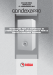
CondexaPRO
Light commercial boiler
Installation
& Servicing
Instructions
THESE INSTRUCTIONS
TO BE RETAINED
BY USER
Vokèra is a licensed member of the Benchmark scheme
which aims to improve the standards of installation and
commissioning of domestic hot water systems in the UK.
CONFORMITY
The Vokera CONDEXA PRO boilers comply with:
• Gas Appliances Directive 90/396/EEC
• Boiler Efficiency Directive 92/42/EEC
• Electromagnetic Compatibility Directive 89/336/EEC
• Low Voltage Directive 73/23/EEC.
• EN 677 standard on condensing boilers.
0085
RANGE
2
MODEL
FUEL
CODE
CONDEXA PRO 50 M
Natural gas - LPG
50-37685-12869-4
CONDEXA PRO 100 M
Natural gas - LPG
50-37685-12867-0
CONDEXA PRO 100 S
Natural gas - LPG
50-37685-12868-7
CONDEXA PRO
Dear Customer,
congratulations on your purchase of a Vokera CONDEXA PRO Boiler. You have chosen proven
technology based on Vokera Ltd experience in this field and if fully compliant with current
European standards. This appliance ensures maximum comfort for an extended period, with high
reliability, efficiency, quality and safety.
The purpose of this manual is to provide all the information that we feel is necessary for the correct
and simple installation of the boiler and must be preserved and made available as and when
requested to ensure correct installation, operation and maintenance.
Full warranty cover applies providing the boiler has been correctly installed, operated and commissioned by qualified personnel. The manufacturer is not liable for any damage caused by the
incorrect layout or installation of the flue system.
Vokera Ltd
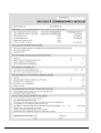
WARRANTY
The Vokera CONDEXA PRO Boiler comes with a SPECIFIC WARRANTY of 24 months (parts and
labour) starting from the date of commissioning or 3 months from date of purchase which ever sooner providing it has been commissioned by Vokera or a qualified engineer and a copy of the commissioning certificate has been returned and filled with Vokera Ltd.
As a result, we suggest that you contact Vokera Service Department or a qualified engineer for
commissioning of the boiler, as described in the conditions listed on the WARRANTY CERTIFICATE supplied with the boiler, which should be read with care.
CONDEXA PRO
3
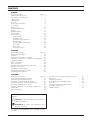
CONTENTS
GENERAL
General warnings
Fundamental safety rules
Description of the appliance
Safety devices
Identification
Structure
Technical specifications
Accessories
Water circuit
Positioning the probes
Pumps
Wiring diagrams
Control panels
User interface
- Display mode
- Readout mode
- Setting the user parameters
- Monitor mode
- Installer programming mode
- Test mode
- Error mode
- Permanent lockout
page
“
“
“
“
“
“
“
“
“
“
“
“
“
“
“
“
“
“
“
“
“
5
5
6
6
7
8
9
9
10
11
11
14
18
19
20
20
21
22
23
24
24
24
INSTALLER
Receiving the product
pag.
Dimensions and weight
“
Handling
“
Room where the boiler is installed
“
Installation in old systems or systems to be upgraded “
Installing the boiler
“
Water connections
“
Fuel connections
“
Flue gas outlet and combustion air intake
“
Electrical connections
“
Installing the outside probe
“
Filling and emptying the systems
“
Preparing for first start-up
“
25
25
26
26
27
28
28
30
30
33
35
36
38
TECHNICAL
Starting for the first time
pag.
Checks during and after first start-up
“
Setting the functional parameters
“
Setting the central heating parameters
“
Setting the domestic hot water parameters
“
Setting the temperature controller
“
Setting the addresses for cascading configurations “
Fault codes
“
List of parameters
“
39
41
45
45
47
48
54
56
58
Conversion from one type of gas to the other
Adjustments
Temporary shutdown
Shutting down for extended periods
Servicing
Cleaning the boiler and dismantling
the inside components
Troubleshooting
“
“
“
“
“
60
62
63
63
64
“
“
64
69
The following symbols are used in some parts of this
booklet:
b CAUTION = actions that require special care and
suitable preparation
a PROHIBITED
= actions that absolutely must
NOT be carried out
This booklet, code 068464EN - Rev. 0 (09/05), contains
76 pages.
4
CONDEXA PRO
GENERAL WARNINGS
b After having removed the packaging, check that the
material supplied is intact and complete; if this is
not the case, contact Vokera Ltd.
b The CONDEXA PRO Boiler must be installed by
qualified personnel as detailed under any current
standards and law applicable and with the instructions provided by Vokera in the manual supplied
with the appliance.
b The boiler must be used for the purposes it has
been expressly manufactured. Vokera Ltd declines
all contractual and extra-contractual liability for
damage caused to persons, animals or things, due
to errors in installation, control, servicing or improper use.
b In the event of water leaks, disconnect the boiler
from the mains power supply, close the water supply and promptly notify Vokera Ltd or other professionally qualified personnel.
b Periodically check that the operating pressure of
the water circuit when cold is 1.5 bar and less than
the maximum limit specified for the appliance. If this
is not the case, contact Vokera Ltd or other professionally qualified personnel.
b If the boiler is not used for an extended period, the
following minimum operations must be completed:
- move the main system switch to "off"
- close the fuel cock and the water cocks on the central heating system
- empty the central heating system if there is the risk
of frost.
b Servicing must be performed on the boiler at least
once a year.
b This manual is an integral part of the boiler and as a
consequence must be kept with care. If the manual
is damaged or lost, contact Vokera Ltd for another
copy.
b Periodically check that the condensate drain is free
of blockages.
FUNDAMENTAL SAFETY RULES
The use of products that operate on fuel, electricity and water requires a number of fundamental safety rules to be
observed, including:
a The boiler must not be used by children or invalid
persons without supervision.
a Electrical devices or appliances, such as switches,
household appliances, etc. must not be used if there
is the smell of gas or unburned fuel. In this case:
- ventilate the room by opening doors and windows;
- close the fuel stopcock;
- promptly contact Vokera Ltd, your gas supplier or
other professionally qualified personnel.
a Do not touch the boiler when barefoot or with wet
parts of the body.
a No service or cleaning operations may be performed without first having disconnected the boiler
from the mains power supply, moving the main
system switch to "off".
a The safety or control devices must not be adjusted
without the authorisation and written instructions
from the manufacturer of the boiler.
a The condensate drain must not be plugged.
CONDEXA PRO
a Do not pull, remove or twist the electrical cables
coming out of the boiler, even if the appliance is
disconnected from the mains power supply.
a The ventilation openings in the room where the
appliance is installed must not be plugged or reduced in size and must comply with any current standards and law applicable.
a Do not expose the boiler to the elements. It is not
designed to operate outdoors and does not have
sufficient frost protection systems.
a Do not switch the boiler off if the outside temperature may fall below ZERO (risk of freezing).
a Do not leave containers and flammable substances
in the room where the boiler is installed.
a The packaging material must not be dispersed in
the environment or left within the reach of children
as it is a potential source of hazard. It must be
disposed of according to the legislation in force.
5
DESCRIPTION OF THE APPLIANCE
The CONDEXA PRO Boiler is a wall-hung condensing
boiler, for heating only, with a premix burner, made up of
one or two heating units, depending on the model.
The CONDEXA PRO Boiler can be combined in a cascading configuration with other heat generators to create
modular heating plants made up of boilers connected to
the same water circuit and with electronic controllers
communicating via bus. The heat output of each heating
unit reaches 48.50 kW (100%, 50°C-30°C) and can be
modulated from 30% to 100%. The efficiency reaches
108.7% and the low flue gas outlet temperature allows
the use of a flame-retardant polypropylene flue (class
B1), with a diameter of just 50 mm and a total equivalent
height of 30 metres.
The versatility of the electronic board makes quick connection possible to all types of central heating and
domestic hot water production systems with storage,
managing three circuits operating with three different
temperatures at the same time.
The individual heating units in cascading configuration
can be activated, as well as by simple rotation, in such a
way that when a certain percentage of output is reached
by the first unit, the other units start automatically, all with
the same load factor.
Specific accessories are available for the boiler, such as
two-way valves or pumps, or devices for taking in the
combustion air.
These ensure adaptability to a vast range of system configurations. Other accessories include water headers
and the flue gas header for cascading installations.
The main features of the CONDEXA PRO Boiler are:
- premix jet burner with constant air-gas ratio
- output from 16.3 to 100 kW (models 100 M and 100 S)
- heat output up to 450 kW, by connecting up to 9 heating units in a cascading configuration, using the waterconnection kit (code 5037685135029), available separately
- maximum flue gas outlet temperature 80°C
- total flue gas outlet and combustion air intake length up
to 30 m, Ø 50 mm
- quick connection of the water and gas headers (optional), with outlet on the right or left
- microprocessor control with self-diagnosis, shown on
LEDs and the display
- the electronic controller can manage up to 60 heating
units in cascading
- frost protection function activated according to the outside temperature and/or the temperature of the boiler
- fitted for room thermostat in the high and low temperature zones
- outside probe to enable the climate control function
- post-circulation function for the central heating and
DHW circuits
- priority settable on the DHW, high or low temperature
circuit
- possibility to manage two circuits with fixed set point or
with climate control using two separate curves
- automatic reversal of the burner ignition order
- emergency function, which in the event of faults on the
Master board still allows the Slave boards to be controlled.
SAFETY DEVICES
The CONDEXA PRO Boiler is fitted with the following safety devices, installed on each heating unit:
Safety thermostat with automatic reset, activated if the
outlet temperature exceeds 90°C, shutting down the burner.
Diagnosis in the water circuit, the minimum flow-rate of
the heat exchange fluid in each heating unit is controlled
by a water differential pressure switch and an electronic
safety system, using an outlet probe and a return probe.
The appliance goes into safety mode if there is insufficient water or circulation.
Flue gas outlet safety device: the flue gas probe, located at the bottom of the exchanger, sets off an alarm in
the event of high flue gas temperatures (> 80°C). In addition, the float in the drain trap prevents the flue gas from
passing through the condensate drain.
Fan safety device: a Hall-effect sensor constantly monitors the rotation speed of the fan. The CONDEXA PRO
Boilers are designed for cascading connection, which
allows the creation of compact and very flexible heating
plants, due to the high degree of modulation.
6
b The activation of the safety devices indicates a
potentially dangerous malfunction on the boiler;
immediately contact Vokera Ltd or other professionally qualified personnel.
After a short wait, try restarting the boiler (see chapter
on starting for the first time).
a The boiler must never be started, even temporarily,
with the safety devices not working or having been
tampered with.
b The safety devices must be replaced by the only
using the original components supplied by the
manufacturer. See the spare parts catalogue supplied with the boiler.
After having performed the repairs or replacements,
check the correct operation of the boiler.
CONDEXA PRO
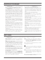
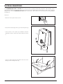
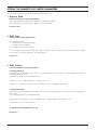
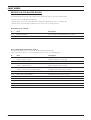
IDENTIFICATION
The boilers can be identified by the:
- Packaging label
This shows the code, the serial number and the
barcode.
2
1
Models
50 M - 100 M
- Rating plate
This shows the technical and performance specifications.
Models
100 S
- Gas label
This is applied on the side of the frame, and
describes the type of fuel used by the boiler, and
the country of destination.
Country of destination:
Type of appliance : B23, C63
Boiler category : II2H3+
Gas supply pressure:
G20 20 mbar
G30+G31 28-30/37 mbar
Manufacturer settings:
G20 - 20 mbar - 2H NATURAL GAS
WARNING
Carefully read the instruction manual before
installing and starting the appliance.
(Laterale DX)
068465EN_1_E0
b If the plates or other means for clearly identifying the product have been tampered with, removed or are missing,
the installation and servicing operations will be much more difficult.
CONDEXA PRO
7
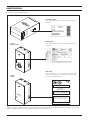
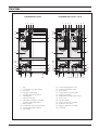
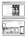
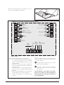
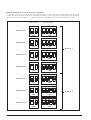
STRUCTURE
CONDEXA PRO 50 M
1
2
3
CONDEXA PRO 100 M - 100 S
4
1
24
2
3
4
1
2
3
4
24
23
23
5
22
6
5
22
6
7
21
21
20
19
20
19
8
9
18
17
9
18
10 17
16
11
14
1
2
3
4
5
6
7
8
13
-
9 10 11 12 -
8
7
12
15
Fan
Combustion air intake fitting
Gas valve
Flue gas outlet fitting
Flue gas analysis test point
Outlet probe
Safety thermostat
SECOND combustion chamber
(models 100 M and 100 S)
Return probe
Condensate collection drain trap
Control panel (90° rotation)
Gas supply
10
16
11
14
13 14 15 16 17 18 19 20 21 22 23 24 -
13
12 16 14 17 13
12 15
Central heating return inlet
Central heating flow outlet
Main switch
Safety valve connection pipe
Safety valve 6 bar
Water differential pressure switch
Drain cock
Flue gas probe
FIRST combustion chamber
Automatic vent valve
Ignition / detection electrode
Panelling
CONDEXA PRO
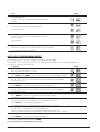
TECHNICAL SPECIFICATIONS
DESCRIPTION
Fuel
Appliance category
Type of appliance
Heat input ref. HHV (min - max)
Heat input ref. NHV (min - max)
Useful heat output (80°/60°C)
Useful heat output (50°/30°C)
Useful efficiency ref. NHV (80°C/60°C)
Useful efficiency ref. NHV (50°C/30°C)
Useful efficiency at 30% ref. NHV (50°C/30°C)
Losses through the chimney with the burner operating
Losses through the chimney with the burner off
Losses through the casing (Tm=70°C )
Flue gas temperature
CO2 at minimum - maximum
CO without air at minimum - maximum less than
NOx without air at minimum - maximum less than
NOx class
Maximum operating pressure, central heating
Maximum admissible temperature
Range of boiler water temperature settings (± 3 °C)
Water content
Power supply
Maximum power input
Index of protection
Quantity of condensate
50 M
16,3 - 50
15 - 45
44,2
48,5
5
169
7,2
CONDEXA PRO
100 M
G20 - G30 - G31
II2H3+
B23 - C63
16,3 - 100
15 - 90
88,30
96,8
98,2
107,7
108,7
1,3
0,1
0,5
Return temp. + 5
8,4 - 9,4
10 - 120
10 - 20
5
6
90
20-80
10
230~50
333
X0D
14,4
100 S
16,3 - 100
15 - 90
88,30
96,8
10
333
14,4
kW
kW
kW
kW
kW
%
%
%
%
%
°C
%
p.p.m.
p.p.m.
bar
°C
°C
l
V~Hz
W
IP
l/h
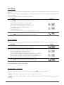
ACCESSORIES
The following accessories are available to be ordered separately.
ACCESSORY
Flue gas header kit
Water connection kit for installations < 100 kW
Water connection kit for installations > 100 kW
Remote control kit
Two-way valve kit
Injection pump kit
Conversion kit for room-sealed operation CONDEXA PRO 50
Conversion kit for room-sealed operation CONDEXA PRO 100
CONDEXA PRO
CODE
5037685135005
5037685135012
5037685135029
5037685135036
5037685135043
5037685135050
5037685135067
5037685135074
9
WATER CIRCUIT
AA
1
2
3
4
5
6
7
8
9
2
1
3
SF
4
-
Fan
Gas valve
Automatic vent valve
Burner
Heat exchanger
Condensate drain trap
Drain cock
Water differential pressure switch
Safety valve (6 bar)
5
AA
SF
SC1
SC2
MI
RI
GAS
6
7
8
- Air intake
- Flue gas outlet
- Safety valve drain
- Condensate drain
- Central heating flow outlet
- Central heating return inlet
- Gas supply
9
SC2
SC1
MI
RI
GAS
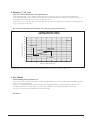
Water-side pressure drop in the boiler
The CONDEXA PRO Boiler does not come with a pump, which must be installed in the system.
When sizing the pump, refer to the water-side pressure drop in the boiler, as shown in the figure below.
1200
1100
1000
Pressure drop (mbar)
900
800
700
600
500
400
300
200
100
0
0
250
500
750
1000
1250
1500
1750
2000
2250
2500
2750
3000
Flow-rate (l/h)
10
CONDEXA PRO
POSITIONING THE PROBES
The following probes/thermostats are installed for each heating unit:
CENTRAL HEATING
OUTLET PROBE
SAFETY THERMOSTAT
FLUE GAS PROBE
CENTRAL HEATING
RETURN PROBE
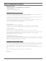
PUMPS
THE CONDEXA PRO Boiler does not come with a pump, which must be installed in the system.
When choosing the pump, refer to the following system diagrams.
Configuration with distribution pumps
Boiler discharge head: 7 mWC
Boiler flow-rate: 2 m3/h for each heating unit.
Also consider the pressure drops in the individual circuit.
PB - DHW pump
PZ1 - Pump in zone 1
(high temperature)
PZ2 - Pump in zone 2
(low temperature)
V2 - Two-way valve
(accessory)
PB
V2
V2
PZ1
PZ2
80°C
50°C
60°C
30°C
CONDEXA PRO
11
Configuration with injection pumps
PB - DHW pump
PZ1 - Pump in zone 1
(high temperature)
PZ2 - Pump in zone 2
(low temperature)
P
- Injection pump
(accessory)
Boiler discharge head: 6 mWC
Boiler flow-rate: 2 m3/h for each pump.
Recommended pump TYPE A for each heating unit.
PB
PZ1
80°C
PZ2
50°C
60°C
P
P
30°C
Configuration with loop pump and valves on the heating units (*)
Boiler discharge head: 7 mWC.
Boiler flow-rate: 2 m3/h for each heating unit.
Recommended: p 50 M: TYPE A; 100M/S: TYPE B; 100M+100S: TYPE C.
PB
PZ1
PZ2
V2
-
DHW pump
Pump in zone 1 (high temperature)
System pump
Two-way valve (accessory)
PB
V2
PZ1
V2
80°C
50°C
60°C
PZ2
30°C
(*) With this configuration the pump in the low temperature circuit is managed externally by a
thermostat (see parameter 34 on page 59).
12
CONDEXA PRO
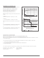
Pump TYPE A
800
Residual head (mbar)
700
600
III
500
400
II
300
I
200
100
0
0
1
2
3
4
5
6
7
8
9
Flow-rate (m /h)
Pump TYPE B
1100
1000
Residual head (mbar)
900
800
700
II
600
500
I
400
300
200
100
0
0
2
4
6
8
10
12
14
16
18
20
Flow-rate (m /h)
Pump TYPE C
1200
1100
Residual head (mbar)
1000
II
900
800
700
I
600
500
400
300
200
100
0
0
4
8
12
16
20
24
28
32
36
40
44
Flow-rate (m /h)
CONDEXA PRO
13
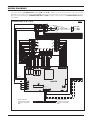
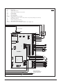
WIRING DIAGRAMS
The control panel on CONDEXA PRO models 50 M and 100 M contains one master board and one or two slave boards,
depending on the output of the boiler. Model 100 S contain just two slave boards. If connecting a series of boilers in cascading, the master board on the CONDEXA PRO 50 M or 100 M manages all the boards on the CONDEXA PRO 100 S boilers via BUS.
CONDEXA PRO 50 M - 100 M
part 1
gv
Main earth
pole
IG
230V~50Hz
Earth
a
Neutral
m
Line
a
m
gv
gv
Joint with
sheath
a
m
gv
gv
R5
m
a
Earth
gv
Earth
gv
Earth
gv
Earth
gv
1
2
3
4
13
Analogic
Input
12
11
10
9
SE 8
8
Circ.2
J11 8
J8 2
J8 1
3 2 1
J9
2 1
J8
9
3
2
1
8 7 6 5 4 3 2 1
J12
Common
4
Outlet NTC circ. 1
6 J12 5
Common
7
DHW NTC
8
Common
9
J11 2
J11 1
J9 1
J9 2
J9 3
14
7 J11 7
8 7 6 5 4 3 2 1
J11
T1
R4
R3
R2
R1
J3
J7
BARCODE
Line 230 Vac.
Neutral 230 Vac.
J10 1
J10 2
J10 3
4 3 2 1
J10
Fuse
F1 3.15 A
15
18
Common
Alarm
R6
J10 4
J10 5
J10 6
6 5
16
J11 6
6
NTC
Outlet NTC circ. 2
19
17
7
J11 4
J11 3
Alarm
VM
TA1
J11 6
J11 5
20
TA2
IA
Common
21
ON
NTC
Circ. 2
Climate NTC
2
J8
1
J8 1
OFF
J11 3
J11 4
4
J11
J11 5
5
J11 8
J11 7
J8 2
CR
22
3
J12 1
1
Max valve
0
J12 2
J9 1
SZ2 6
PZ2
J12 3
J9 2
3
J9
2
5
24
23
J12 5
J12 4
Neautral DHW pump
Line DHW pump
Neutral pump 1
Line Pump 1
Neutral pump 3
Line Pompa 3
Neutral Max. valve
Off - Max. valve
On - Max. valve
J9 3
Pump 3
J11 2
NTC
J12 3 R.T. circ. 2
J12 2 Common
J12 1 R.T. circ. 1
1
J11 1
2
SB 4
J12 6
2
J10 1
PZ1
25
J12 6 Common
J12 5 Analogic Input
J12 4 Common
J10 2
3
26
Com.
J10
3
1
NTC
SZ1 2
Bus
J10 3
27
Pump
1
PB
J12 7
4
28
24V
J10 4
Pump
J12 8
5
J12 9
6
J10 5
J12 9 24V remote cont.
J12 8 Common
J12 7 Ebus remote cont.
J10 6
MASTER
J2
J6
J5
MC
1
BUS J14
3
2
4
J4
J1
PC
Bus line with male
connector for connection
to another model 100S
boiler.
14
Bus line with female
connector for connection
to another model 100S
boiler.
CONDEXA PRO
b The pumps should be connected by installing suitable contactors with manual emergency operation.
part 2
to main earth pole
to main earth pole
IG1
T1
Line
5
m
a
Neutral
5
6
5
m
a
8
VG
Safety thermostat
7
m
a
Gas valve
TS
Diff. pressure switch
13
m
a
PD
4
1
2
n
Earth
J2
6
7
6
3 4
J1
1
WD
J12
5
2
m
4 5
3
v
g
b
gv
3
C
6
3
Neutral
4
J2
m
a
1
Line
J6
2
m
a
2
T1
Earth
Earth
Earth
4
J15
F1
gv
gv
gv
1
J8
3
1
1
1
J14
Fuse 4A
5
J6
J7
IG2
EA/ER
EA/ER
SLAVE 2
3
SLAVE 1
1
2
J11
Blower (+)
Hall sensor imput
Hall sensor power
PC J5
Hall sensor common
Blower (-)
v
g
n
10
a
3
a
m
9
4
5
J16
2
J17
J4
Outlet NTC
1
1 2
J9
m
a
m
11
6
T3
J10
m
b
Return NTC
SM
Flue gas NTC
SR
1 2
J9
SF
Main
BUS 1
PB
PZ1
PZ2
VM
CR
IA
SB
SZ1
SZ2
SE
TA1
TA2
- DHW pump
- Pump in zone 1
(high temperature)
- Pump in zone 2
(low temperature)
- Mixing valve
- Remote control (accessory)
- Analogue input
- DHW probe
- Probe in zone 1
- Probe in zone 2
- Outside probe
- Room thermostat in zone 1
(high temperature)
- Room thermostat in zone 2
(low temperature)
SYSTEM
CONDEXA PRO
BUS 2
VG
TS
PD
SM
SR
SF
EA/ER
C
-
IG
IG1
IG2
J10/J17 -
Gas valve
Safety thermostat
Water differential pressure switch
Outlet probe
Return probe
Flue gas probe
Ignition/detection electrode
Cable for connection to two-way valve
or injection pump (accessories)
Main boiler switch
FIRST heating unit switch
SECOND heating unit switch
Microswitches for setting the address
(see page 54)
HEATING UNIT
15
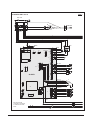
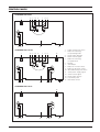
CONDEXA PRO 100 S
part 1
Main earth
pole
gv
IG
3
a
Earth
m
Neutral
230V~50Hz
Line
Joint with
sheath
a
m
gv
gv
a
m
gv
gv
to main earth pole
IG1
EA/ER
1
Fuse 4A
J8
J15
3
1
1
J7
J14
F1
Earth
Earth
Earth
m
a
Line
Neutral
C
m
a
8
VG
Safety thermostat
7
m
a
Gas valve
TS
Diff. pressure switch
PD
4
1
2
n
m
a
13
7
6
3 4
J1
1
WD
J12
5
m
4 5
3
v
g
b
2
6
5
4
J2
m
a
6
3
2
T1
gv
gv
gv
5
J6
3
SLAVE 1
1
2
J11
Blower (+)
m
b
Hall sensor imput
v
Hall sensor power
Hall sensor common g
Blower (-)
PC J5
n
11
10
a
9
J16
Main
Return NTC
a
m
3
J4
J17
Outlet NTC
2
1 2
J9
m
a
m
1
J10
4
5
6
T3
Flue gas NTC
SM
SR
SF
BUS 1
Bus line with male
connector for connection
to another model 100S
boiler.
16
L = 1500 mm
CONDEXA PRO
VG
TS
PD
SM
SR
SF
EA/ER C
IG
IG1
IG2
J10/J17 -
part 2
Gas valve
Safety thermostat
Water differential pressure switch
Outlet probe
Return probe
Flue gas probe
Ignition/detection electrode
Cable for connection to two-way valve or injection pump (accessories)
Main boiler switch
FIRST heating unit switch
SECOND heating unit switch
Microswitches for setting the address (see page 54)
gv
to main earth pole
IG2
EA/ER
1
Fuse 4A
J8
J15
3
1
1
J7
J14
F1
Earth
Earth
Earth
m
a
Line
Neutral
C
m
a
8
VG
Safety thermostat
7
m
a
Gas Valve
TS
Diff. pressure switch
PD
4
1
2
n
m
a
13
7
6
3 4
J1
1
WD
J12
5
m
4 5
3
v
g
b
2
6
5
4
J2
m
a
6
3
2
T1
gv
gv
gv
5
J6
3
SLAVE 2
1
2
J11
Blower (+)
m
b
Hall sensor imput
v
Hall sensor power
Hall sensor common g
Blower (-)
PC J5
n
11
a
3
a
m
10
J16
J4
Return NTC
9
J17
Outlet NTC
2
1 2
J9
m
a
m
1
J10
4
5
6
T3
Flue gas NTC
Main
SM
SR
SF
BUS 1
L = 1200 mm
CONDEXA PRO
Bus line with female
connector for connection
to another model 100S
boiler.
17
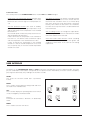
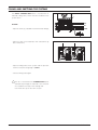
CONTROL PANELS
CONDEXA PRO 50 M
1
2 3
45
6
11 12 13
7
8
9
14
15
1 - FIRST heating unit switch
2 - Button for selecting
the operating mode
3 - Reset button (Master)
4 - Boiler lockout signal
5 - Button for selecting
the parameters
6 - Display
7 - Save button
8 - Button to increase values
9 - Button to decrease values
10 - SECOND heating unit switch
11 - Slave power supply signal
12 - Slave lockout signal
13 - Reset button (Slave)
14 - Instrument panel
15 - Main boiler switch
CONDEXA PRO 100 M
1
2 3
11 12 13
45
6
7
14
8
9
10
13 12 11
15
CONDEXA PRO 100 S
1
11 12 13
18
10
14
13 12 11
15
CONDEXA PRO
Functional notes
The control panel on the CONDEXA PRO Boiler models 50 M and 100 M manages:
- The domestic hot water priority function whereby when
there is demand for domestic hot water, the master
board can also serve the high or low temperature circuit.
- The frost protection function, also active in standby,
which starts the pump in the high temperature circuit
and the loop pump if the temperature in the manifold
falls below 5°C.
If the outside probe is fitted, the pumps start if the outside temperature falls below 3°C.
If after 10 minutes the temperature in the manifold is
less than 5°C, one burner starts at maximum output,
until the temperature in the manifold reaches 20°C.
If after 10 minutes the temperature in the manifold
exceeds 5°C but the outside temperature is less than
3°C, the pumps stay on until the outside temperature
exceeds this value.
- The dispersion function: the pumps in the high and low
temperature circuits remain on for 5 minutes after the
last burner has shut down. There is a 6 minute delay
from when the burner shuts down before closing the
two-way valve. When the last burner has shut down,
the valve closes only when there is no demand from the
room thermostat.
- The cascading function: to manage the output delivered by the system, the minimum and maximum number
of burners started can be selected.
- The burner on/off control function: in both cascading
modes there is a function that limits the ignition and
shutdown of the burners in the event of low heating
requirement.
USER INTERFACE
The buttons on the CONDEXA PRO 50 M and 100 M control panel have different functions in different modes. For example, the combination of two buttons corresponds to one specific function. Alternatively, a function can be activated by
pressing the button briefly or by holding it for around 5 seconds.
RESET
This resets the electronic board after a permanent
lockout.
MODE
This is used to enter parameter setting mode and monitor mode on the individual units.
SEL
This is used to display the operating status of the various
circuits managed by the Master board.
+ and Permettono di aumentare o diminuire un determinato
valore
MEMO
This is used to save the new values.
CONDEXA PRO
19
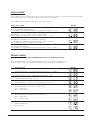
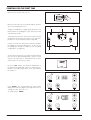
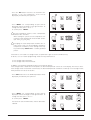
DISPLAY MODE
The red LED (see ref. 4 on page 18) comes on in the event of faults that cause the permanent lockout of a heating unit
(normal operation is reset only by pressing the Master or Slave reset button).
The 3 digits with seven segments display the status of the system:
Status of the system
Display
No central heating or DHW demand.
The two digits on the right display the outlet temperature T1. E.g.: T1 = 30°C
Demand from circuit no.1 or from circuits 1 and 2 together.
The two digits on the right display the outlet temp. T1. E.g.: T1 = 80°C
Demand from the DHW circuit or simultaneous operation.
The two digits on the right display the outlet temp. T1 E.g.: T1 = 80°C.
The decimal point after the 1st digit on the left flashes
Demand from the 2nd circuit
The two digits on the right display the outlet temperature T1. E.g. T1 = 80°C.
READOUT MODE
(TEMPERATURE VALUES AND OPERATING STATUS OF THE VARIOUS CIRCUITS)
Press the "SEL" button to scroll forwards and display the values set for the individual circuits.
The values listed below will be displayed in sequence when pressing the "SEL" button.
Value displayed
20
1
Outlet temperature T1 in the high temperature circuit. E.g. : T1 = 80°C
2
DHW temperature T3. E.g.: storage heater temperature = 50°C
3
Outside temperature T4. E.g. T4 = 7°C
4
Outlet temperature in 2nd circuit or low temperature circuit T6
5
Room thermostat in the 1st circuit, closed or open.
OFF = contact open
ON = contact closed
6
Room thermostat in the 2nd circuit, closed or open
OFF = contact open
ON = contact closed
7
0-10V analogue input
E.g. 5.5V, 10V
Display
CONDEXA PRO
Value displayed
8
Operating status of the mixing valve
E.g.: closing, opening, standby
9
Operating status of the main pump
E.g.: pump not working, pump working
10
Operating status of the DHW pump
E.g.: pump not working, pump working
11
Operating status of the secondary pump
E.g.: pump not working, pump working
Display
To exit the display of the values, press the "MEMO" button.
If no operation is performed for 5 minutes, the board automatically returns to Display mode.
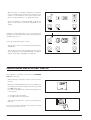
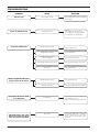
SETTING THE USER PARAMETERS
Pressing "SEL" displays the following values in sequence:
- Outlet temperature T1 in the high temperature circuit
- DHW temperature T3
- Outlet temperature in the second circuit or low temperature circuit T6.
To change the corresponding set points:
- Press "MODE", the corresponding value will be displayed and the two digits on the right will flash.
- If the value does not need to be changed, press "MODE" again to return to Display mode.
- If the value needs to be changed, press "+" or "-" until reaching the desired value. Press "MEMO" to save the new value.
The value displayed will stop flashing and the display will return to Display mode.
Example: changing the set point in the low temperature circuit from 50°C to 40°C
Procedure
1
E.g.: Value read on the display in the high temperature circuit 80°C
2
Press "SEL" to access Readout mode, press the button again
and scroll the first digit to 6 so as to display the set value, E.g.: 50°C
CONDEXA PRO
Display
21
Procedure
3
Press “MODE”
4
Press “-” to change the set point to the desired value. E.g.: 40°C.
5
Press “MEMO” to save the new value
6
After 3 seconds Display mode resumes, with the new value set.
Display
If after having pressed “MODE” no change is made for 10 seconds (because the desired value is already set), the operation of the board returns to Display mode.
If after having pressed “+” or “-” no other button is pressed for at least one minute, Display mode resumes. If this happens, the new value is not saved.
MONITOR MODE
Press “MODE” for 5 seconds to access "Monitor" mode. This mode is used to check the operating values of each individual unit in the system (addresses from 1 to 60).
Operation
1
The boiler is operating with the high temperature circuit at 80°C
2
Press “MODE” for 5 seconds. The display indicates that the values
and the operating status of unit 1 can be read.
3
Press “+” or “-” to scroll and read the values for the desired unit.
4
Pressing “SEL” on the display shows the 1st value for the selected unit.
Pressing the "SEL" button again displays the following values.
E.g. outlet temperature 70°C
5
To exit Monitor mode, press “MODE”.
If within 5 minutes no button is pressed or no operation is performed,
Display mode resumes.
Display
Press “SEL” to display the subsequent values for the individual unit:
Value
22
1
Outlet temperature E.g.: 70°C
2
Return temperature E.g.: 50°C
3
Flue gas temperature E.g.: 60°C
4
Ionisation current (index from 0 to 99)
E.g.: ionisation current index 44
Display
CONDEXA PRO
Value
5
Fan PWM signal (%).
If PWM = 100%, this corresponds to 99 on the display.
E.g.: 66 %
6
Flow switch contact open/closed (not active)
E.g.: contact open
7
Pump or motorised valve on the individual unit on/off
E.g.: Pump ON
E.g.: Pump OFF
8
Maximum ionisation current (range from 0 to 99) at first attempt
E.g.: maximum ionisation current 80
Display
INSTALLER PROGRAMMING MODE
The installer parameters can be changed by entering the password (22).
The password for the installer level allows access to display and change the user and installer parameters.
Procedure to enter programming mode:
Procedure
1
E.g.: the outlet temperature T1 is 80°C
2
Press “MODE” and “MEMO”. After 5 seconds the second and third digit will flash.
3
Use “+” and “-” to enter the first number in the password on the centre digit.
E.g.: password = X2
4
Press “MEMO” to save the second number in the password.
5
Use “+” and “-” to enter the first number in the password on the centre digit.
E.g.: password = 22
5
Press “MEMO” to confirm the password, if the password is wrong
the board returns to Display mode.
6
Press “+” and “-” to scroll the parameters enabled by the password.
Press “MODE” to start setting the parameters.
The code P-XX and the corresponding value will alternate on the display.
7
Use “+” and “-” to change the value of the parameter.
Whenever a button is pressed, the alternating display of the parameter
and the corresponding value is stopped for 5 seconds and only the value is shown.
8
Press “MEMO” to save the new value of the parameter.
Display
To exit installer programming mode press “MEMO”.
For the complete list of parameters see page 58.
CONDEXA PRO
23
TEST MODE
In Test mode, a high temperature heating demand can be generated corresponding to maximum output and minimum
output.
All the system fans must be on. If the installer switches off some of the Slaves, the others, connected to the Master, must
continue operating.
To enter Test mode from Display mode, proceed as follows:
Procedure
1
Display
Press “MODE” and “+” at the same time per 5 seconds.
After 5 seconds the maximum or minimum speed
can be selected using the “+” and “-” buttons.
All the system fans will operate at the selected speed.
The first digit will show the selected speed:
H = maximum speed
L = minimum speed.
The other two digits will show the outlet temperature. E.g.: T1 = 80°C.
2
Press “MEMO” to exit Test mode and return to Display mode.
ERROR MODE
The display starts flashing when there is a fault on any of the heating units. Proceed as follows to identify the faults.
Procedure
1
The display starts flashing to signal one or more errors.
1.b
Press “+”: the display will show the address of the
first unit, alternating with the first error code.
Press “+” again to display the other errors on this unit.
The errors on the following unit with faults will be displayed in sequence,
by pressing “+” Pressing "-" displays the errors in reverse order
(E.g. unit 2 error code E02). If the errors come from the Master board,
these are displayed as errors on unit 00 (U 00 + error code).
2
Press “MODE” to exit Error mode and return to Display mode.
Display
For the complete list of errors, see page 56.
PERMANENT LOCKOUT
In the event where the burners are in permanent lockout, press “RESET” to resume operation.
If “RESET” is pressed in readout mode, all the Slave heating units will be reset.
If “RESET” is pressed when displaying the error that caused the permanent lockout, only the heating unit in question
will be reset.
24
CONDEXA PRO
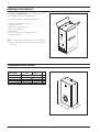
RECEIVING THE PRODUCT
The Vokera CONDEXA PRO Boiler is supplied in a single package protected by a cardboard box.
The following material is supplied with the boiler:
-
Installation and operation manual
Warranty certificate
Water pressure test certificate
Spare parts catalogue
Outside probe
Kit for conversion from natural gas to LPG
Assembly template.
b The Installation and operation manual is an integral
part of the appliance and must be read and kept
with care.
2
1
DIMENSIONS AND WEIGHT
Description
W
D
H
Net weight
Weight with packaging
50 M
100 M - 100 S
600
380
1000
~ 60
~ 65
~ 90
~ 95
mm
mm
mm
kg
kg
H
L
CONDEXA PRO
P
25
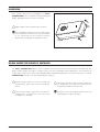
HANDLING
Once having removed the packaging, the Vokera
CONDEXA PRO Boiler is handled manually by tilting and
lifting it, grabbing the points shown in the figure.
b Adopt suitable safety and protection measures.
a The packaging material must not be dispersed in
the environment or left within the reach of children
as it is a potential source of hazard. It must be
disposed of according to the legislation in force.
ROOM WHERE THE BOILER IS INSTALLED
The Vokera CONDEXA PRO boiler must be installed in rooms used exclusively for this purpose, provided with adequately sized ventilation openings, in compliance with any current standards and low applicable. If the combustion air
is taken from outside (accessories code 5037685135067 and 5037685135074) the room where the boiler is installed,
CONDEXA PRO operates as a room-sealed appliance (type C).
b Provide enough clearance to access the safety and
b If the boilers operate on gas fuel with a higher spe-
b Check that the index of protection of the boiler is
a The boilers cannot be installed outside as they are
control devices and to carry out the servicing operations.
suitable for the characteristics of the room where
the appliance is installed.
26
cific weight than air, the electrical parts must be
located at least 500 mm from the floor.
not designed for outdoor operation.
CONDEXA PRO
INSTALLATION IN OLD SYSTEMS OR SYSTEMS TO BE UPGRADED
Where Vokera CONDEXA PRO Boilers are installed in
old systems or systems to be upgraded, check that:
- The flue is suitable for the temperature of the products
of combustion with condensing operation, calculated
and manufactured according to the standards, as straight as possible, airtight, insulated and not blocked or
choked. It must also be fitted with suitable condensate
collection and drain systems
- The electrical system has been installed in compliance
with the relevant standards by qualified personnel
- The fuel supply line and any cylinders or tanks (LPG)
are made and installed according to the relevant standards
- The expansion vessel can completely absorb the
expansion of the fluid contained in the system
- The flow-rate and the discharge head of the pump are
suitable for the characteristics of the system
- The system is flushed, treated, vented and pressure
tested. To clean the system, see the paragraph on
"Water connections", page 28. The manufacturer is not
liable for any damage caused by the incorrect flushing,
treatment and venting etc of the system.
- The condensate drain system (drain trap) is connected
and runs into the sewerage drain or a neutraliser, where
required by the legislation in force.
- A treatment system is available for special supply/topup water requirements (for the reference values, see
the table).
b The manufacturer is not liable for any damage cau-
sed by the incorrect layout or installation of the flue
system which must be in-accordance with any current standards and law applicable
SUPPLY WATER VALUES
pH
Conductivity
Chloride ions
Sulphuric acid ions
Total iron
Alkalinity M
Total hardness
Sulphur ions
Ammonia ions
Silica ions
6-8
less than
less than
less than
less than
less than
less than
none
none
less than
200 mV/cm (25°C)
50 ppm
50 ppm
0,3 ppm
50 ppm
35°F
30 ppm
b The flues for condensing boilers are made from
special material and differ from those used for standard boilers.
CONDEXA PRO
27
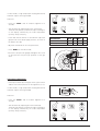
INSTALLING THE BOILER
The Vokera CONDEXA PRO Boiler must be secured to
a solid brick wall using the bracket (1).
1
3
For installation:
- Position the bracket (1) on the wall at a height of
around 200 cm from the ground, using a spirit level to
make sure that the holes are perfectly horizontal
- Mark the fastening holes on the wall
- Drill the holes and insert the expansion plugs (2)
- Fasten the bracket to the wall using the screws (3)
- Hook the boiler to the bracket.
2
b The height of the boiler should chosen so as to simplify the dismantling and servicing operations.
b The Vokera CONDEXA PRO Boiler is not designed
for outdoor installation.
WATER CONNECTIONS
The Vokera CONDEXA PRO Boilers are designed and
built to be installed in central heating and domestic hot
water systems. The characteristics of the water fittings
are as follows:
MI RI Gas -
Central heating flow outlet 1" M
Central heating return inlet 1" M
Gas supply 3/4" M
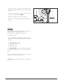
CONDENSATE COLLECTION
Identify the condensate drain (S) located at the bottom of
the boiler and then:
- remove the ring nut/nuts (1)
- pass the hose (2) through the hole and replace the ring
nut on the outside.
Pipe the condensate into the sewerage drain or a neutraliser, where required and in-accordance with any legislation in force.
b The manufacturer is not liable for any damage caused by the failure to install the condensate drain
pipe.
b The condensate drain pipe must be watertight.
28
1
2
S
MI RI
GAS MI RI
GAS
CONDEXA PRO
CLEANING THE SYSTEM
This preliminary operation is required when installing the heat generator in pre-existing systems, and is also recommended in new systems, so as to remove any scale, impurities, processing residues etc. Power Flushing is recommended for system cleaning.
To clean the system, if the old heat generator is still
installed in the system, proceed as follows:
- Add scale-remover into the system water circuit;
- Operate the system with the heat generator on for
around 7 days;
- Empty the dirty water from the system and flush with
clean water. Repeat the operation until the system is
clean.
If the old heat generator is not installed or not available,
use a pump to circulate the water with the additive in the
system for around 10 days, and carry out flushing as
described in the previous point. At the end of the cleaning operations, before installing the boiler, an additive
should be introduced into the water circuit that provides
protection against corrosion and fouling.
400
WATER CONNECTION KIT code 5037685135012
b For additional information on the type and the use
of the additives, contact Vokera Ltd or a suitable
additives manufacture.
1000
water connection kit for installations up to 100 kW
(code 5037685135012)
1 gas manifold, diameter 45 mm
1 central heating outlet manifold, diameter 45 mm
1 central heating return manifold, diameter 45 mm
125 125 200
Water connection kits
To assist the construction of the water circuit, two accessory kits are available, featuring water headers and support brackets:
MI
RI
GAS
700
2" female fittings.
1 gas manifold, diameter 3"
1 insulated central heating outlet manifold, Ø 3”
1 insulated central heating return manifold, Ø 3”
WATER CONNECTION KIT code 5037685135029
150
400
water connection kit for installations above 100 kW
(code 5037685135029).
DN 80 - PN 6 flanged pipes.
rest to the central heating flow outlet, in the direction of water flow.
CONDEXA PRO
300
MI
RI
250
b The outlet probe should be fitted in the socket nea-
1000
flow outlet as the Master boiler, so as to minimise
the length of the cables to the pumps, the outlet
probe and any storage heater probe.
250
b Identify the unit that is closest to the central heating
GAS
1500
29
FUEL CONNECTIONS
The Vokera CONDEXA PRO Boiler must be connected
to the natural gas or LPG supply in compliance with the
relevant standards in force.
Before making the connections, check that:
- the type of gas is the same that the appliance is set for
- the pipes are thoroughly clean
- the gas supply pipes are the same size or larger than
the fitting on the boiler (3/4"), with a pressure drop that
is less than the pressure drop between the gas supply
and the appliance.
When installation is completed, check that the joints are
all tight, as required by the installation standards.
A suitable filter should be installed on the gas line.
FLUE GAS OUTLET AND COMBUSTION AIR INTAKE
The flue and the fitting to the flue must be made in compliance with the standards and the legislation in force, as
well as with local regulations.
The pipes used must be rigid and resistant to temperature, condensate and mechanical stress, and airtight.
275
A
b Non-insulated flues are potential sources of danger.
S
275
A
37
S
61
212
A - Air intake Ø 50 mm
(Conversion kit for room-sealed operation
CONDEXA PRO 50 code 5037685135067
Conversion kit for room-sealed operation
CONDEXA PRO 100 code 5037685135074)
S - Flue Ø 50 mm
B23 Fan upstream. Combustion air intake directly
from the room where the boiler is installed. Flue
gas exhaust through horizontal or vertical pipes,
fitted with ventilation openings.
C63 Fan upstream. Combustion air intake and flue
gas exhaust without terminals.
C63
B23
b
30
Please refer to any current standards and law
applicable to flues and ventilation.
CONDEXA PRO
MAXIMUM LENGTH OF THE PIPES
model 50 M
The maximum equivalent length of the sum of the 50 mm
intake pipes and flues is 30 metres, with a pressure drop
of 2 metres for each 90° bend.
Installation of a single boiler with flue passing inside
a compartment (open flue operation).
For this type of operation, make sure that the size of the
compartment complies with the standards in force.
The figure on the side shows the minimum dimensions of
the compartment when passing one flue (model 50 M) or
two flues (models 100 M or 100 S).
b Parameter 36 (see page 59) needs to be set based
on the type of gas and the length of the chimney.
Minimum inside dimensions of the compartment
for the passage of 1 flue, diameter 50 mm
Circular compartment
Square compartment
63 mm
71 mm
50mm
model 100 M
50mm
models 50 M + 100 S
Minimum inside dimensions of the compartment
for the passage of 2 flues, diameter 50 mm
Circular compartment
Minimum dimensions of the compartment
for the passage of three flues, diameter 50 mm
Rectangular compartment
Square compartment
Rectangular compartment
230 mm
20 50 20 50 20
Ø 160 mm
20
50
90 mm
20
20
50
90 mm
20
160 mm
20
20
20
20
20 50 20 50 20
CONDEXA PRO
50 20
50 20
50 20
50 20
50 20
160 mm
31
PREPARING THE CONDENSATE DRAIN
The condensate produced by the boiler during normal
operation must be drained at atmospheric pressure and
must conform to any current standards and law applicable.
- install a neutraliser where required by law.
i ≥ 3°
i
b Specific pipes for condensing boilers must be
used. For installation, follow the instructions
provided with the kit.
Minimum
distance
300 mm
Drain trap along the drain pipe
If the vertical or horizontal section of the drain pipe
needs to be extended by more than 4 metres, a drain
trap must be installed at the foot of the pipe.
The useful height of the drain trap must be at least 300
mm. The discharge of the drain trap must then be connected to the sewerage system.
Minimum
distance
10 mm
Condensate collector
(at atmospheric pressure)
32
i > 3%
Mains
sewers
CONDEXA PRO
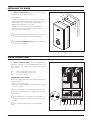
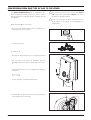
ELECTRICAL CONNECTIONS
The CONDEXA PRO 50 M and 100 M boilers leave the factory completely wired, with the power cable already connected, and only require the connection of the room thermostats, the outside probe and the pumps used, to the corresponding terminals. For the CONDEXA PRO 100 S boiler, only the Bus cable needs to be connected (see the wiring diagram
on page 16).
To do this:
ON
- Move the main system switch to "off"
OFF
- Unscrew the fastening screws (1) on the front panel (2)
- Pull the base of the panel (2) outwards and then
upwards to release it from the frame and then remove
it
2
1
- Turn the control panel (3) and remove the rear cover,
taking out the locking screws (4)
3
4
CONDEXA PRO
33
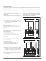
- Identify the terminal block (5) and make the connections, as in the diagram shown below.
5
TERMINAL BLOCK INSIDE THE MASTER CONTROL PANEL
28
Probe in zone 1, SZ1
high temperature
PB (*)
27
DHW pump
26
PZ1 (*)
25
High Temperature
system pump
24
23
Storage heater probe
2
3
SB
4
PZ2 (*) Loop pump or
Pbas (*) Low temperature
5
Probe in zone 2,
low temperature
SZ2
Outside probe
SE
6
system pump
22
21
1
VM (*)
7
8
Mixing valve
20
19
18
Contact for
alarm signal
TA2
Low temperature
room thermostat
0-10V
analogue
input
BUS
IA
COM
24V
CR
Remote
control
TA1
High temperature
room thermostat
17 16 15 14 13 12 11 10
9
(*) 230V~50Hz
b The following measures are compulsory:
1 - the use of an omnipolar thermal overload switch, mains disconnecting switch, compliant
with the CEI-EN standards (minimum contact
opening 3 mm);
2 - respect the connection L (Line) - N (Neutral).
Leave the earth wire around 2 cm longer than
the power wires;
3 - use wires with a cross-section greater than or
equal to 1.5 mm2, complete with pointed end
terminals;
4 - refer to the wiring diagrams in this booklet for
any operations on the electrical system;
5 - connect the appliance to an effective earth
system.
34
b The pumps should be connected by installing suitable contactors with manual emergency operation.
a The gas and/or water pipes must not be
used to earth the appliance.
a The power supply and room thermostat
cables must not run near hot surfaces
(outlet pipes).
The manufacturer is not liable for any damage due to the failure to earth the appliance
and to observe the information provided on
the wiring diagrams.
CONDEXA PRO
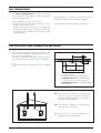
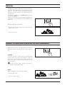
INSTALLING THE OUTSIDE PROBE
The correct positioning of the outside probe is fundamental for the correct operation of the climate control function.
The probe must be installed outside of the building being heated, at a height of around 2/3 of the wall facing NORTH or
NORTH-WEST, and away from flues, doors, windows and areas exposed to direct sunlight.
Fastening the outside probe to the wall
- Unscrew the cover on the probe protection box, turning
it anticlockwise to access the terminal block and the
fastening holes
- Trace the fastening points using the protection box as
the template
- Remove the box and drill the holes for the 5x25 expansion plugs
- Fasten the box to the wall using the two plugs supplied
- Unscrew the nut on the cable gland, pass a two-wire
cable through (cross-section from 0.5 to 1mm2, not
supplied) to connect the probe to terminals 7 and 8
(see the diagram on page 34)
- Connect the two wires on the cable to the terminal
block, without needing to identify the polarity
- Tighten the nut on the cable gland and close the cover
on the protection box.
b The probe should be placed on a smooth section of
the wall; in the event of exposed brick walls or uneven walls, a smooth contact area should be used.
b The maximum length of the connection between
the outside probe and the control panel is 50 m.
b The connection cable between the probe and con-
trol panel must not have junctions; if required, these
must be sealed and adequately protected.
b Any conduits used for the connection cable must
be separate from the power cables (230Vac).
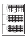
Conversion table valid for all probes
Temperature measured (°C) - Resistance of the probes (Ω).
T (°C)
R (°Ω)
T (°C)
R (°Ω)
T (°C)
R (°Ω)
T (°C)
R (°Ω)
T (°C)
R (°Ω)
T (°C)
-20
-19
-18
-17
-16
-15
-14
-13
-12
-11
-10
-9
-8
-7
-6
-5
-4
-3
-2
-1
67739
64571
61568
58719
56016
53452
51018
48707
46513
44429
42449
40568
38780
37079
35463
33925
32461
31069
29743
28481
0
1
2
3
4
5
6
7
8
9
10
11
12
13
14
15
16
17
18
19
27279
26135
25044
24004
23014
22069
21168
20309
19489
18706
17959
17245
16563
15912
15289
14694
14126
13582
13062
12565
20
21
22
23
24
25
26
27
28
29
30
31
32
33
34
35
36
37
38
39
12090
11634
11199
10781
10382
9999
9633
9281
8945
8622
8313
8016
7731
7458
7196
6944
6702
6470
6247
6033
40
41
42
43
44
45
46
47
48
49
50
51
52
53
54
55
56
57
58
59
5828
5630
5440
5258
5082
4913
4751
4595
4444
4300
4161
4026
3897
3773
3653
3538
3426
3319
3216
3116
60
61
62
63
64
65
66
67
68
69
70
71
72
73
74
75
76
77
78
79
3021
2928
2839
2753
2669
2589
2512
2437
2365
2296
2229
2164
2101
2040
1982
1925
1870
1817
1766
1717
80
81
82
83
84
85
86
87
88
89
90
91
92
93
94
95
96
97
98
99
CONDEXA PRO
R (°Ω) T (°C)
1669
1622
1577
1534
1491
1451
1411
1373
1336
1300
1266
1232
1199
1168
1137
1108
1079
1051
1024
998
100
101
102
103
104
105
106
107
108
109
110
R (°Ω)
973
948
925
901
879
857
836
815
796
776
757
35
FILLING AND EMPTYING THE SYSTEMS
The Vokera CONDEXA PRO Boiler is not fitted with an
automatic filling valve, which must be installed on the
system return.
1
MI
FILLING
RI
- Open the valves (1) installed on the boiler water fittings;
- Open the caps on the automatic vent valve/valves (2)
two or three turns;
GAS
2
2
- Open the filling valve on the system until the pressure
shown on the pressure gauge is 1,5 bar;
- Close the filling valve again.
b The air is vented from the CONDEXA PRO boiler
automatically through the automatic vent valve/valves installed on the top of the heating units.
Check that the cap on the valve is open.
36
CONDEXA PRO
EMPTYING
ON
Before starting to empty the system, disconnect the
power supply by moving the main system switch to "off".
OFF
Emptying the BOILER
- Close the valves (1) installed on the boiler water fittings;
1
MI
RI
GAS
- Connect a plastic hose to the drain cock (4), on each
heating unit, and open the cock;
b Before opening the drain cock (4), protect the elec-
4
4
trical devices underneath against water spillage.
Emptying the SYSTEM
1
- Check that the valves (1), installed on the water circuit,
are open;
MI
RI
GAS
- Connect a plastic hose to the drain cock (5), fitted on
the system return line, and open the cock.
5
CONDEXA PRO
37
PREPARING FOR FIRST START-UP
Before starting the system and running the functional
tests on the Vokera CONDEXA PRO Boiler, check that:
- The fuel valve and valves in the central heating system
are open;
- The type of gas and the supply pressure are correct for
the boiler;
- The system is filled, pressure in the water circuit, when
cold, is around 1,5 bar and the circuit has been
vented;
- The system expansion vessel is suitably pre-charged;
- The electrical connections have been performed correctly.
b The pumps should be connected by installing sui-
table contactors with manual emergency operation.
- Check that the cap on the vent valve/valves is
unscrewed;
- The pumps turn freely: loosen the inspection screw
and check with a flathead screwdriver that the motor
shaft is rotating without impediments.
b Before loosening or removing the seal cap on the
pump, protect the electrical devices underneath
against water spillage.
- The flues have been properly made and installed.
38
CONDEXA PRO
STARTING FOR THE FIRST TIME
- Move the main system switch to "on";
ON
OFF
- Move the main switch (1) on the boiler and the switches
(2) on each heating unit to "on".
2
4
2
The green SLAVE power supply signal (3) flashes. The
boiler performs a self-diagnosis cycle, after which it will
enter DISPLAY mode.
The display (4) shows the status of the system and the
temperature measured by the probe in the "high temperature" circuit (see Display mode on page 20).
If there are more than two boilers installed, configure
the addresses from the third boiler on. To do this, see
the paragraph "Setting the addresses for cascading
configurations" on page 54).
3
1
- Set the room thermostats in the high and low temperature zone to the desired temperature (~20°C) or if the
systems are fitted with a timer-thermostat or timer,
check that this is on and set (~20°C).
- Press the “SEL” button: the maximum temperature of
the boiler will be displayed, that is, the maximum temperature in the high temperature circuit, preceded by
the symbol "1".
- Press “MODE”: the corresponding set point will be
displayed and the two digits on the right will flash. To
change the value, press “+” or “-”.
To confirm press “MEMO”.
CONDEXA PRO
39
- Press the “SEL”button four times: the maximum temperature in the low temperature circuit will be
displayed, preceded by the symbol "6".
- Press “MODE”: the corresponding set point will be
displayed and the two digits on the right will flash. To
change the value, press “+” or “-”.
To confirm press “MEMO”.
b For low temperature systems, select a temperature
between 20°C and 45°C.
When setting the system as "Low temperature", the
maximum outlet temperature will be limited at 50°C
(Par. 23=T_CH_Low_limit).
b Changing the outlet temperature modifies the cli-
mate control curve (see the paragraph "Setting the
temperature controller"). These settings must only
be performed by Vokera Ltd or a suitably qualified
person.
If the boiler is connected to a storage heater, set parameter 6 (pre-set to 0=no DHW service).
To do this, access "Installer programming" mode and set parameter 6 to:
2 = for storage heater with probe
6 = for storage heater with thermostat.
In addition, set parameter 9 (DHW_Priority) to 2 for absolute priority.
If the storage heater is fitted with an NTC probe, the desired temperature can be set on the display, from 10°C to 50°C.
If the storage heater is fitted with a thermostat, the desired temperature should be set directly on the storage heater,
while parameter 3 must be left at 50°C.
- Press “SEL”button twice: the DHW temperature will be
displayed, preceded by the symbol "3".
- Press “MODE”: the corresponding set point will be
displayed and the two digits on the right will flash. To
change the value, press “+” or “-”.
To confirm press “MEMO”.
The boiler will start in DHW mode, until the demand is
satisfied.
40
CONDEXA PRO
When the boiler is in Standby, the display on the Master
unit is in Readout mode and the three digits show the
number "1", followed by the value of the outlet temperature. The green LED (ref. 11 on page 18) flashes.
See the paragraph on "DISPLAY MODE", page 20, for
details on the various information displayed by the
system.
If ignition or operating faults occur on any heating unit,
the display on the Master boiler starts flashing and the
red LED (4) comes on.
4
There are two possible types of errors:
- Type A errors, which can only be deactivated by pressing RESET;
- Type E errors, which are deactivated when the causes
are no longer present (see ERROR MODE on page 24
and the "Fault codes" paragraph on page 56).
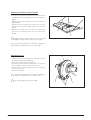
CHECKS DURING AND AFTER FIRST START-UP
When ignition is complete, check that the CONDEXA
PRO boiler correctly:
- Starts and stops, closing the contacts on the zone thermostats;
- Displays the DHW temperature (only if the storage heater is fitted) and central heating temperature, pressing
the “SEL”button twice;
Check, if the storage heater is fitted, that parameter "6"
is set correctly:
2 = storage heater with probe
6 = storage heater with thermostat
and check that operation is correct, by opening a hot
water tap.
ON
OFF
Check the complete shutdown of the boiler by moving
the main system switch to "off".
CONDEXA PRO
41
After a few minutes of continuous operation controlled by
the room thermostat, the adhesives and the processing
residues will have evaporated, and the following checks
can be completed:
- check the gas supply pressure;
- check combustion,
ON
OFF
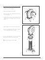
CHECKING THE GAS SUPPLY PRESSURE
- Move the main system switch to "off";
- Unscrew the fastening screws (1) on the front panel (2);
2
- Pull the base of the panel (2) outwards and then
upwards to release it from the frame and then remove
it;
1
- Unscrew the screw on the pressure test point (3), located upstream of the gas valve, around two turns, and
connect a pressure gauge;
- Power-up the boiler by moving the main system switch
and the main switch/switches on the appliance to "on".
3
ON
OFF
42
CONDEXA PRO
In TEST mode, a high temperature heating demand at
maximum output can be generated.
To do this:
- Press the “MODE” and “+” buttons together for 5
seconds;
- Start the boiler by adjusting the room thermostat.
The boiler will operate at maximum output showing "H"
on the display, followed by the outlet temperature
(chimney sweep function);
- Check that with the burner on at maximum output the
gas pressure is the rated supply pressure, as shown in
the table to the side;
DESCRIPTION
G20
Wobbe index
Rated supply pressure
G30 G31
45,7
80,6
70,7
MJ/m3
20
28-30
37
mbar
- Adjust the thermostat so as to stop the boiler;
- Press “MEMO” to exit TEST mode;
- Disconnect the pressure gauge and tighten the screw
on the pressure test point (3) upstream of the gas
valve.
3
CHECKING COMBUSTION
- Power-up the boiler by moving the main system switch
and the main switch/switches on the appliance to "on";
In TEST mode, a high temperature heating demand at
maximum output can be generated.
ON
OFF
To do this:
- Press the “MODE” and “+” buttons together for 5
seconds;
- Start the boiler by adjusting the room thermostat.
The boiler will operate at maximum output showing "H"
on the display, followed by the outlet temperature
(chimney sweep function).
CONDEXA PRO
43
- Combustion can be checked by unscrewing the cap
(4) and inserting the analyser probe in the available
position;
- Once having completed the check, stop the chimney
sweep function by pressing “MEMO”;
- Adjust the thermostat so as to stop the boiler;
4
- Remove the analyser probe and carefully retighten the
cap (4);
FAN SPEED
The fan speed is controlled automatically based on the
type of gas and the length of the flue (L).
This information is managed by parameter 36.
To change the settings:
- Enter "INSTALLER PROGRAMMING MODE" following
the procedure described on page 23, and set parameter 36 to:
1
2
3
4
=
=
=
=
natural gas and L<15 m
natural gas and L>15 m
LPG and L<15 m
LPG and L>15 m.
The CONDEXA PRO boilers are supplied for operation
on G20 (natural gas), with a flue L<15m (parameter
36=1).
Once the checks are complete, replace the front panel
and secure it using the same screws.
b All checks must be performed by a suitably qualified person.
44
CONDEXA PRO
SETTING THE FUNCTIONAL PARAMETERS
The functions of the central heating high temperature and low temperature circuits and the DHW circuits can be set
based on the system requirements, by setting the functional parameters.
The first three parameters are accessible at a user level, while the remaining parameters require the password to be
entered ("22", see page 23).
To access the user parameters, press the "SEL" button, after which the following values will be displayed:
- Outlet temperature in the high temperature circuit T1
- Temperature in the DHW circuit T3
- Outlet temperature in the low temperature circuit T6
To change the corresponding set points:
- Press "MODE", the corresponding value will be displayed and the two digits on the right will flash.
- Press “+/-” until reaching the desired value. Press "MEMO" to save the new value. The value displayed will stop flashing and will be valid after 3 seconds.
For a detailed description of all the parameters and the default values see page 58.
SETTING THE CENTRAL HEATING PARAMETERS
The following functions can be set for central heating:
1 Setpoint_T_CH_High
Set point in the high temperature circuit (parameter 1)
If the operating mode is set to "fixed set point" (par. 14=CH_type_high=0), this is the objective temperature.
If the operating mode is set to "climate control" (par. 14=1), this is the maximum objective temperature for the minimum outside temperature (T_out_min=par. 37, pre-set to 0°C).
Parameter 18 (T_CH_high_foot, pre-set to 50°C) defines the minimum set point for the maximum outside temperature (T_out_max, pre-set to 18°C).
Pre-set to 70°C with upper limit set by par. 17 (T_CH_high_limit, pre-set to 80°C).
CLIMATE CONTROL CURVE
HIGH TEMPERATURE CIRCUIT
100
90
T_CH_High_foot
Max heating
requirement
Outlet temperature (°C)
80
T_out_min
70
60
50
T_out_max
T_CH_High
40
30
20
10
0
25
20
15
10
5
0
-5
-10
-15
-20
Outside temperature (°C)
CONDEXA PRO
45
2 Setpoint_T_CH_Low
Set point in the low temperature circuit (parameter 3)
If the operating mode is set to "fixed set point" (par. 22=CH_type_low=0), this is the objective temperature.
If the operating mode is set to "climate control" (par. 22=1), this is the maximum objective temperature for the minimum outside temperature (T_out_min=par. 37, pre-set to 0°C).
Parameter 24 (T_CH_low_foot, pre-set to 25°C) defines the minimum set point for the maximum outside temperature (T_out_max, pre-set to 18°C).
Pre-set to 40°C with upper limit set by par. 23 (T_CH_Low_limit, pre-set to 50°C).
CLIMATE CONTROL CURVE
LOW TEMPERATURE CIRCUIT
100
90
Outlet temperature (°C)
80
70
T_CH_Low_foot
60
Max heating
requirement
50
T_out_min
40
30
T_out_max
20
T_CH_Low
10
0
25
20
15
10
5
0
-5
-10
-15
-20
Outside temperature (°C)
Consequently, each circuit can operate with a fixed set point or using a set climate control curve.
3 CH_Priority
Central heating priority (parameter 16)
If this is set to 0 the system works without central heating priority, that is, with the high temperature and low temperature circuit served in parallel.
If set to 1, the demand from the low temperature circuit is ignored and the corresponding pump remains off.
The demand from the low temperature circuit is only accepted when the high temperature circuit is off.
Vice-versa, if set to 2 the low temperature circuit has priority.
Pre-set to 0.
46
CONDEXA PRO
SETTING THE DOMESTIC HOT WATER PARAMETERS
The following functions can be set for the domestic hot water circuit:
1 Setpoint_DHW
Domestic hot water set point (parameter 2)
This is the temperature value for the production of domestic hot water.
The maximum limit is set by par. 8 (T_DHW_limit, pre-set to 60°C).
Pre-set to 50°C.
2 DHW_Type
Type of storage heater (parameter 6)
0
1
2
6
=
=
=
=
No DHW service
Rapid heat exchanger with probe
Storage heater with probe
Storage heater with thermostat
For the storage heater with thermostat, if the input is a closed contact, the domestic hot water demand is activated,
if it is an open contact the demand is no longer present.
Pre-set to 0.
3 DHW_Priority
Domestic hot water priority (parameter 9)
0 = Sliding priority A
The purpose of the sliding priority A function is to allow the system to also serve the central heating function when
the heating demand is low.
The system responds to the heating demand if:
(Setpoint_Ch - 50°C) < Manifold temp. < (Setpoint_Ch + 1°C)
Setpoint_Ch = Set point in the high or low temperature circuit, according to the demand.
1 = Sliding priority B
The purpose of the sliding priority B function is to ensure that the system does not stop the central heating service
for too long.
The system responds to the heating demand if:
(Setpoint_Dhw+T_Tank_extra) - 50°C < Manifold temp. < (Setpoint_Dhw+T_Tank_extra) + 1°C
T_tank_extra = Par. 10 = pre-set to 30°C.
2 = Absolute priority (DHW service only)
Pre-set to 0.
CONDEXA PRO
47
SETTING THE TEMPERATURE CONTROLLER
1 Attenuation_High
Attenuation function for the HIGH TEMPERATURE circuit (parameter 21)
Two cases are possible:
- Operation with fixed set point, Par. 14=0
- Operation with climate control Par. 14=1.
OPERATION WITH FIXED SET POINT, PAR. 14=0
With attenuation in the high temperature circuit disabled, Par21=0, when the thermostat in the high temperature circuit closes, the heating demand is signalled. When opening, the system stops.
The Master controller starts the pump in the high temperature circuit PZ1 and the loop pump PZ3, if the parameter
for the third pump is set to 0 (Par. 34=0 ), otherwise the third pump remains off.
The set point for the high temperature circuit can be set on the Master controller, Setpoint_T_CH_High = Par. 1, preset to 70°C, in the range from 10°C to T_CH_high_limit=Par 17, in turn pre-set to 80°C.
The set point used will be the value set for parameter 1.
The burner is on when:
Manifold Temperature <=Set point – Start hysteresis.
The start hysteresis can be set, CH_High_mod_hyst_on = Par. 19, pre-set to 7°C, between 0 and 20°C.
The Master controller converts the heating demand into an output requirement for each slave controller.
The burners are off when:
Manifold Temperature >=Set point + Stop hysteresis.
The stop hysteresis can be set (CH_High_mod_Hyst_off=Par. 20, pre-set to 3, between 0 and 20°C).
When the attenuation in the high temperature circuit parameter is enabled, Par. 21≠0, the contact on the high temperature thermostat is ignored, and a demand for heat in the high temperature circuit is present when:
Manifold Temperature <=Set point – Start hysteresis
The demand for heat stops when:
Manifold Temperature >=Set point + Stop hysteresis.
The set point in this case coincides with the value set for parameter 1 (Setpoint_T_CH_High), if the contact of the
high temperature thermostat is closed, while it is calculated as the value set for parameter 1 minus the attenuation
(Setpoint_T_CH_High-Attenuation_high) if the contact is open.
OPERATION WITH CLIMATE CONTROL, PAR. 14=1
If the attenuation in the high temperature circuit parameter is equal to 0, attenuation_high=Par. 21=0, the behaviour
is the same as in the previous paragraph, except the set point is calculated according to the outside temperature.
If the outside temperature = T out_min=Par. 37, pre-set to 0°C, then set point =setpoint_T_Ch_high
If the outside temperature = T out_max=Par. 38, pre-set to 18°C, then set point T_CH_high_ foot=Par. 18, preset to
50°C.
Between the two outside temperature values, the set point is calculated linearly.
Pre-set to 0.
48
CONDEXA PRO
2 Attenuation_Low
Attenuation function for the LOW TEMPERATURE circuit (parameter 25).
This paragraph is similar to the previous one, however in this case referred to the low temperature circuit.
Two cases are possible:
- Operation with fixed set point, Par. 22=0
- Operation with climate control Par. 22=1.
OPERATION WITH FIXED SET POINT, PAR. 22=0
With attenuation in the low temperature circuit disabled, Par. 25=0, when the thermostat in the low temperature circuit closes, the heating demand is signalled. When opening, the system stops.
The Master controller starts the pump in the low temperature circuit PZ3.
The set point for the low temperature circuit can be set on the Master controller, Setpoint_T_CH_low = Par. 3, pre-set
to 40°C in the range from 10°C to T_CH_Low_limit=Par. 23, in turn pre-set to 50°C.
The set point used will be the value set for parameter 3.
The burner is on when:
Manifold Temperature <=Set point – Start hysteresis.
The start hysteresis can be set, CH_Low_mod_hyst_on = Par. 26, pre-set to 5°C, between 0 and 20°C.
The Master controller converts the heating demand into an output requirement for each slave controller.
The burners are off when:
Manifold Temperature >=Set point + Stop hysteresis..
The stop hysteresis can be set (CH_Low_mod_Hyst_off=Par. 27, pre-set to 3, between 0 and 20°C).
When the attenuation in the low temperature circuit parameter is enabled, Par. 25≠0, the contact on the low temperature thermostat is ignored, and a demand for heat in the high temperature circuit is present when:
Manifold Temperature <=Set point – Start hysteresis
The demand for heat stops when:
Manifold Temperature >=Set point + Stop hysteresis.
The set point in this case coincides with the value set for parameter 3 (Setpoint_t_ch_low) if the contact of the low
temperature thermostat is closed, while it is calculated as the value set for parameter 3 minus the attenuation
(Setpoint_t_ch_low-Attenuation_low) if the contact is open.
OPERATION WITH CLIMATE CONTROL, PAR. 22=1
If the attenuation in the low temperature circuit parameter is equal to 0, attenuation_low=Par. 25=0, behaviour is the
same as in the previous paragraph, except the set point is calculated according to the outside temperature.
If the outside temperature = T out_min=Par. 37, pre-set to 0°C, then set point =setpoint_T_Ch_low.
If the outside temperature = T out_max=Par. 38, pre-set to 18°C, then set point T_ch_low_foot=Par. 24, pre-set to
50°C.
Between the two outside temperature values, the set point is calculated linearly.
Pre-set to 0.
CONDEXA PRO
49
3 T_out_correct
Outside temperature correction (parameter 39)
Normally the value displayed is the value read by the micro-controller, plus or minus a correction value
(T displayed = T read by the probe +/- correction).
The outside temperature value read can be corrected by changing the value of parameter 39, (the limit allowed for
the correction is +/- 30 °C). In this phase, the use of a reference thermometer is suggested.
Pre-set to 0.
4 T4_frost_protection
Frost protection (parameter 35)
The electronic controller features a frost protection function that is also active in standby. The frost protection function has two levels, the first that starts the pump, and the second that starts the pump and the burner.
If the Manifold Temperature ≤5°C, the pump in the high temperature circuit and the loop pump are started, or, when
CH_type=1 and the outside probe is connected, if the Outside Temperature ≤3°C (par. 35), the pump in the high temperature circuit and the loop pump are started.
If after 10 minutes the Manifold Temperature ≤5°C, a burner is started at maximum output, until
the Manifold Temperature ≥20°C.
If after 10 minutes the Manifold Temperature ≥5°C but, when CH_type=1 (Par. 14 or 22) and the outside probe is connected, the Outside Temperature ≤3°C (par. 35), the pump continues operating until the Outside Temperature ≥3°C.
Pre-set to 3.
5 Power_control_mode
Cascading management (parameter 33)
To manage the output delivered by the system, two cascading strategies are available. In both cases, the Master
controller can only start a new burner when another is already on.
If the Master controller needs to increase the number of burners on, it first checks that the subsequent burner can
be started: no error is present and temperature of the boiler is less than the maximum.
Otherwise, it checks another burner. If no burner is available, the master decreases the number of burners to be started.
MODE: MINIMUM NUMBER OF BURNERS ON (PAR. 33=0)
The output of the system is modulated by a PID control algorithm, where the value controlled is the temperature in
the manifold, and the set point refers to the active circuit (set point in the high or low temperature circuit, or DHW set
point). The PID control directly manages the last 2 burners started, while the previous burners operate at maximum
output.
If the Manifold Temperature < set point – 5°C, the next burner is started, and both are managed by the PID control
algorithm.
The Master controller waits 30 seconds, and then if the Manifold Temperature < set point - 5°C, another burner is
started.
The first burner works at maximum output, while the other two are managed by the PID control algorithm.
If the Manifold Temperature > set point + 2°C, the last burner is stopped, the other two most recently started burners
are managed by the PID control algorithm, while the others work at maximum output. The Master controller waits 30
seconds before checking the situation again.
50
CONDEXA PRO
MODE: MAXIMUM NUMBER OF BURNERS ON (PAR.33=1)
All the burners are controlled by the same PID control algorithm, where the value controlled is the temperature in the
manifold, and the set point refers to the active circuit (set point in the high or low temperature circuit, or DHW set
point).
If the Manifold Temperature < set point – 5°C, the next burner is started.
The Master controller waits 30 seconds, and then
if the Manifold Temperature < set point - 5°C, another burner is started.
If the Manifold Temperature > set point + 2°C the last burner is stopped. The Master controller waits 30 seconds
before checking the situation again.
ADDITIONAL CASCADING MANAGEMENT FUNCTIONS
Rotation of burner ignition sequence
When Master controller is switched on, the burner with address 1 is the first in the sequence. After 24 hours, the burner with address 2 becomes the first burner, while the burner with address 1 becomes the last in the sequence.
Limitation of starts/stops
In both cascading strategies, after each start or stop, a minimum time must expire before the Master can start or stop
any of the burners.
Rapid start/stop
In both modes a function is available for rapidly reaching stable operating conditions and shutting down.
If the Manifold Temperature < set point - 70°C the burners are started at 2 second intervals.
If the Manifold Temperature > set point + 4°C the burners are stopped at 2 second intervals.
Low load
The low load function prevents the burners from stating and stopping when there is a low heating demand. The conditions for the activation of the Low Load function are checked on every Slave board, which sends the request to
enable the function to the Master.
During normal operation, the set point in the active circuit (set point in the high or low temperature circuit, or DHW
set point) is sent to the Slave boards, and the temperature of the heating unit is checked by each Slave board:
if the Boiler temperature > Set point – 8°C or
the Boiler temperature > 85°C - 8°C, the signal to start the burner is disabled.
When the Slave board reads a boiler temperature greater than 85°C three times when the burner is on, the heating
unit is stopped and the start-up procedure is enabled again.
Emergency function
In the event of faults on the Master board, there are two was of manually controlling the Slave boards:
- By eBUS and manifold probe
Disconnect the power supply from the system, unplug the BUS. Set the address 000000 on all the Slave boards
(J10 and J17 OFF). Connect a power supply between 21 and 28 Vac to the BUS.
If the Manifold Temperature < Emergency Temp. (Par.40; pre-set to 70°C; settable between 10 and 80°C) all the
burners operate at maximum output.
If the Manifold Temperature > Emergency Temp. + 5°C all the burners are stopped;
- By PC
Disconnect the power supply from the system, unplug the BUS and connect the PC interface. The output of the
burners can be sent directly to the Slave boards using the PC.
b In the event of faults, contact Vokera Ltd or a suitably qualified person.
CONDEXA PRO
51
Managing the heating demand in the high temperature circuit by analogue input (Par. 14=2 or 3)
The room thermostat in the high temperature circuit is ignored for the heating demand, and the input signal is used to
calculate the output or the system set point.
There is just one analogue input (see terminals 13-14 on the wiring diagram on page 34) on the Master board and this
can also be used for the low temperature circuit (Par.22). The analogue input cannot be used for both the circuits.
ANALOGUE INPUT FOR HEAT OUTPUT, PAR. 14=2 (PAR. 22=2 FOR LOW TEMPERATURE CIRCUITS)
The demand for the high temperature (low temperature) circuit is made according to the following rules:
0-2Vdc: no demand from the high temperature (low temperature) circuit
Heat output (kW)
2-9Vdc: 2-9Vdc: the demand for heat is converted into
an output demand for each Slave. An input of 2V
corresponds to minimum output, 9V to maximum
output (Par.15). Between 2V and 9V the output is
calculated linearly. The hysteresis for the end of
the demand is 0.2V and therefore the demand is
active above 2V and ends below 1.8V.
The burner starts when:
Outlet Temp. ≤ Setpoint_Ch_high (Par.1) –
Ch_high_mod_hist_on (Par.19)
(Outlet Temp. ≤ Setpoint_Ch_low (Par.3) –
Ch_low_mod_hist_on (Par.26))
The burner stops when:
Outlet Temp. > Setpoint_Ch_high (Par.1) +
Ch_high_hist_off (Par.20)
(Outlet Temp. > Setpoint_Ch_low (Par.3) +
Ch_low_hist_off (Par.27))
250
200
150
100
50
0
1
2
3
4
5
6
7
8
9
10
9
10
Voltage (Volt)
ANALOGUE INPUT FOR TEMPERATURE, PAR. 14=3 (PAR. 22=3 FOR LOW TEMPERATURE CIRCUITS)
The demand for the high temperature (low temperature) circuit is made according to the following rules:
0-2Vdc: no demand from the high temperature (low temperature) circuit
52
80
70
Setpoint
2-9Vdc: the demand for heat is converted into an output
requirement for each Slave, by the PID_CH_high
(PID_CH_low) algorithm. 2V corresponds to a
set point of T_Ch_high_foot, Par. 18
(T_Ch_low_foot, Par. 24), 9V to a set point of
Setpoint_Ch_high, Par.1 (Setpoint_Ch_low,
Par.3). Between 2V and 9V the set point is calculated linearly. The hysteresis for the end of the
demand is 0.2V and therefore the demand is
active above 2V and ends below 1.8V.
The burner starts when:
Outlet Temp. ≤ Setpoint_ch_high (Par. 1) –
Ch_high_hist_on (Par 19)
(Outlet Temp. ≤ Setpoint_ch_low (Par. 3) –
Ch_low_mod_hist_on (Par.26))
The burner stops when:
Outlet Temp. > Setpoint_ch_high (Par. 1) +
Ch_high_hist_off (Par. 20)
(Outlet Temp. > Setpoint_ch_low (Par. 3) +
Ch_low_hist_off (Par. 27)).
90
60
50
40
30
20
10
0
1
2
3
4
5
6
7
8
Voltage (Volt)
CONDEXA PRO
MANAGEMENT OF THE MIXING VALVE
The mixing valve is controlled by the following parameters:
Before opening or closing, the valve waits the time set for
Par.30.
Manifold Temperature
55
Mix_valve_step_open_time: Par.28 pre-set to 5s
Mix_valve_step_close_time: Par.29 pre-set to 7s
Mix_valve_interval_time: Par.30 pre-set to 5s
Mix_valve_p_hyst: Par.31 pre-set to 2°C
Mix_valve_still_hyst: Par.32 pre-set to 2°C
45
35
25
15
5
-5
It opens if:
T_low inlet temperature < Setpoint_low – Par32
0
5
10
15
20
Time (s)
If:
T_ low inlet temperature < Setpoint_low – Par31 it opens
for a time equal to half of the value set for Par. 28
If:
T_ low inlet temperature > Setpoint_low + Par31 it closes
for a time equal to half of the value set for Par. 29.
Open
2
1
0
-1
Close
Within the interval, the valve remains in the current position.
3
Valve Closing-Opening (s)
It closes if:
T_ low inlet temperature > Setpoint_low + Par32
-2
-3
-4
20
25
30
35
40
45
50
55
60
Mixer Outlet Temperature (°C)
default
Par. 31 = 10
Safety functions on the Slave boards
When the Outlet Temperature > 90°C for 5s, the Slave board shuts down (no. 46).
When the Return Temperature > 80°C for 5s, the Slave board shuts down (no. 47).
When the Flue Gas Temperature > 80°C for 5s, the Slave board shuts down (no. 48) and the fan operates for 10 minutes at maximum speed.
The Slave board can protect the main exchanger against the dangers of low water circulation, in three ways:
1 = by flow switch (water differential pressure switch)
2 = by controlling the difference between the outlet and return temperature DT
3 = by flow switch and DT
The control on the DT uses a parameter, DT_max (pre-set to 35°C) and limits the output of the burner as follows:
if DT_max -5°C > DT > DT max – 10°C
if DT_max > DT > DT_max –5°C
if D_T > D_T_max
CONDEXA PRO
burner modulation
burner at minimum
burner off.
53
SETTING THE ADDRESSES FOR CASCADING CONFIGURATIONS
The microswitches on the slave boards are factory-set so as to interface a master boiler (50 M or 100 M) to a slave boiler (100 S). If other slave boilers need to be connected, the microswitches must be set again.
Accessing the slave boards
- Move the main system switch to "off"
- Access the slave boards inside the boiler control panel (see the steps described on page 65)
- Follow the address setting procedure described below, and then connect the boilers using the special bus cable (see
the wiring diagrams starting from page 14).
Setting the ADDRESSES
Each slave board (one for each heat generator) must be configured so as to be recognised in the right sequence by the
master board.
The slave generators should first of all be divided into blocks; the system can manage up to 15 blocks of four slave
generators each.
For example, if 5 slave generators are connected to a master, there are two blocks: the first made up of four slave generators and the second of one slave generator.
Consequently, the addresses should be set as follows:
- Identify the block of four that the slave generator being configured belongs to (for example block 1, 2, ………, up to
block15)
- Identify the position of the slave generator inside each block (e.g. position 1, 2, 3 or 4).
T3
1
ON
OFF
SLAVE address
J10
2
SLAVE board
J17
1
Main
2
ON
3
OFF
BLOCK address
4
Table of BLOCK addresses
Microswitches
Table of SLAVE addresses
Microswitches
54
1
2
SLAVE
address
OFF
OFF
ON
ON
OFF
ON
OFF
ON
1
2
3
4
1
2
3
4
OFF
OFF
OFF
OFF
OFF
OFF
OFF
OFF
ON
ON
ON
OFF
ON
ON
ON
ON
OFF
OFF
OFF
OFF
ON
ON
ON
ON
OFF
OFF
OFF
OFF
ON
ON
ON
ON
OFF
OFF
ON
ON
OFF
OFF
ON
ON
OFF
OFF
ON
ON
OFF
OFF
ON
ON
OFF
ON
OFF
ON
OFF
ON
OFF
ON
OFF
ON
OFF
ON
OFF
ON
OFF
ON
BLOCK
Emergency
1st block
2nd block
3rd block
4th block
5th block
6th block
7th block
8th block
9th block
10th block
11th block
12th block
13th block
14th block
15th block
CONDEXA PRO
Example configuration of a set of 7 burners in cascading
If installing a set of seven slave generators, there are two blocks: the first made up of four generators, and the second
of three. Therefore, two blocks need to be configured, with address 1 and 2 respectively, and the generators belonging
to the first block must have address 1, 2, 3 and 4, and those belonging to the second block address 1, 2 and 3.
SLAVE address
BLOCK address
ON
ON
Generator no. 1
1
2
1
2
OFF
ON
3
OFF
4
ON
Generator no. 2
1
2
1
2
OFF
3
OFF
4
Block no. 1
ON
ON
Generator no. 3
1
2
1
2
OFF
ON
3
OFF
4
ON
Generator no. 4
1
2
1
2
OFF
ON
3
OFF
4
ON
Generator no. 1
1
2
1
2
OFF
ON
3
OFF
4
ON
Generator no. 2
Block no. 2
1
2
1
2
OFF
ON
3
OFF
4
ON
Generator no. 3
1
2
OFF
CONDEXA PRO
1
2
3
OFF
4
55
FAULT CODES
ERRORS ON THE MASTER BOARD
The following tables provide a description of the errors that may occur on the Master board.
The errors can be divided into two groups:
- Type A errors, which can only be deactivated by pressing RESET (see ref. 3 on page 18).
- Type E errors, which are deactivated when the causes are no longer present.
Permanent errors, TYPE A
N°
Error
Description
A 16
EEPROM ERROR
The contents of the EEPROM are not correct
A 18
INCORRECT EEPROM SIGNATURE
EEPROM not recognised by the processor
Errors deactivated automatically, TYPE E
The following errors may occur, and can be deactivated automatically.
If any one of these errors occurs, the red LED comes on (see ref. 4 on page 18).
N°
Error
Description
E 02
NTC1 open (or not connected)
(NTC1 = outlet sensor)
Probe manifold not connected
E 04
NTC3 OPEN
Storage heater probe not connected
E 18
NTC1 short-circuited
(NTC1 = outlet sensor)
Probe manifold short-circuited
NTC3 short-circuited
(NTC3 = sensor on the storage heater)
Storage heater probe short-circuited
E 23
REFHI TOO LOW ERROR
Temperature measured not correct
E 24
REFHI TOO HIGH ERROR
Temperature measured not correct
E 25
EEPROM READING ERROR
The EEPROM is not legible
E 25
REFLO TOO LOW ERROR
Temperature measured not correct
E 26
REFLO TOO HIGH ERROR
Temperatura misurata non corretta
E 32
SLAVES NON PRESENT
There are no slave boards connected
E 34
50 Hz ERROR
The mains frequency is not 50 Hz
E 20
56
CONDEXA PRO
ERRORS ON THE SLAVE BOARD
List of slave errors: manual reset (see ref. 3 on page 18)
If slave errors with manual reset occur, the Slave reset button can be used (see ref. 13 on page 18).
No.
Error
A 01
5 failed attempts at ignition
A 02
Too many failed ignitions
A 04
Gas valve relay error
A 05
Gas valve relay error
A 06
Safety relay does not close
A 07
Safety relay does not open
A 08
Safety relay open when should be closed
A 09
RAM error
A 10
EEPROM error
A 11
Fan error
A 12
Incorrect EEPROM signature
A 16
Safety relay closed when should be open
A 17
Outlet sensor error for having exceeded the max. outlet temperature
A 18
Return sensor error for having exceeded the max. return temperature
A 19
Flue gas sensor error for having exceeded the max. flue gas temperature
(with this error the fan operates at maximum speed )
A 20
The flame is extinguished too late after the gas valve closes
A 24
Fan error
List of slave errors: automatic reset
NO.
Error
E 33
Phase error
E 34
Reset button error
E 35
Water pressure switch error – contact not closed
E 36
EEPROM reading error
E 37
Flame detection error – line and neutral reversed
E 38
Flue gas probe short-circuited
E 39
Flue gas probe open
E 40
50 Hz error
E 41
Communication error
E 42
Outlet probe short-circuited
E 43
Outlet probe with contact open
E 44
Return probe short-circuited
E 45
Return probe with contact open
E 46
Outlet probe error for having exceeded the temperature limit
E 47
Return probe error for having exceeded the temperature limit
E 48
Flue gas probe error for having exceeded the temperature limit (with this error, the fan operates at max.)
CONDEXA PRO
57
LIST OF PARAMETERS
No. Name
lower
limit
upper
limit
default
setting
UOM
10
Par. 17
70
°C
Description
User parameters
1
SetPoint_ch_high
If Par14=0 this is the high temperature circuit set point
If Par14=1 this is the maximum temperature
in the high temperature circuit
2
SetPoint_DHW
10
Par. 8
50
°C
3
SetPoint_ch_low
10
Par. 23
40
°C
If Par22=0 this is the low temperature circuit set point
If Par22=1 this is the maximum temperature
in the low temperature circuit
INSTALLER parameters accessible by password: 22
6
DHW_type
0
6
0
0 = No DHW service
1 = Instant with NTC probe
2 = Storage heater with NTC probe
5 = Instant with flow switch
6 = Storage heater with thermostat
7
P_DHW_max
1
255
230
8
T_DHW_limit
10
80
60
9
DHW_priority
0
2
0
Maximum speed/output in DHW
Limit for user DHW setting
0 = Sliding A
1 = Sliding B
2 = Absolute priority
10 T_tank_extra
0
50
30
°C
Modular temp system in DHW = Par. 2 + Par. 10
11 T_tank_hyst_up
0
20
1
°C
Upper DHW differential
12 T_tank_hyst_down
0
20
5
°C
Lower DHW differential
13 N°_bruc_DHW
1
60
60
14 CH_type_high
0
3
1
Maximum no. of burners in DHW
0 = Fixed temperature
1 = Climate with outside probe
2 = 0-10 Vdc for heat output
3 = 0-10 Vdc for temperature
15 P_ch_max
1
255
230
16 CH_priority
0
2
0
Maximum speed/output in CH
0 = No priority between circuits
1 = Priority to the high temperature circuit
2 = Priority to the low temperature circuit
17 T_CH_high_limit
10
80
80
°C
18 T_CH_high_foot
10
Par. 1
50
°C
Limit for user high temperature circuit setting
Min. high circuit set point at the maximum
outside temperature (Par. 38)
19 CH_high_hyst_on
0
20
7
°C
Start hysteresis in high temperature circ.
20 CH_high_hyst_off
0
20
3
°C
Stop hysteresis in high temperature circ.
21 Attenuation_high
0
70
0
°C
22 CH_type_low
0
3
1
Set point attenuation with room thermo. open
0 = Fixed temperature
1 = Climate with outside probe
2 = 0-10 Vdc for heat output
3 = 0-10 Vdc for temperature
23 T_CH_low_limit
10
70
50
°C
24 T_CH_low_foot
10
Par. 13
25
°C
Limit for user low temperature circuit setting
Min. low circuit set point - at the maximum
outside temperature (Par. 38)
25 Attenuation_low
58
0
70
0
°C
Set point attenuation with room thermo. open
CONDEXA PRO
No. Name
lower
limit
upper
limit
default
settinglimit
UOM
limit
Description
setting
26 CH_low_hyst_on
0
20
5
°C
27 CH_low_hyst_off
0
20
3
°C
28 Mix_valve_step_ open_time 0
255
5
s
29 Mix_valve_step_close_time 0
255
7
s
30 Mix_valve_interval_time 0
255
5
s
Mixing valve delay
31 Mixing_p_hyst
0
255
2
°C
Hysteresis for maximum valve opening
32 Mixing_still_hyst
0
255
2
°C
33 Power control mode
0
1
1
Start hysteresis in low circuit calculated
on the mixer outlet temp
Stop hysteresis in low circuit calculated
on the mixer outlet temp
For each step the valve opens
1/2 of the set value
For each step the valve closes
1/2 of the set value
0 = Minimum number of burners
1 = Maximum number of burners
34 3° pump
0
1
0
0 = System/loop
1 = Low temperature circuit
35 Frost protection
36 Gas_type
-30
15
3
1
7
1
°C
System
1 = NG with flue < 15m
2 = NG with flue > 15m
3 = LPG with flue < 15m
4 = LPG with flue > 15m
37 T_out_min
38 T_out_max
-20
30
0
°C
0
30
18
°C
39 T_out_correct
-30
30
0
°C
40 T_emergency
10
80
70
°C
41 Parameter_reset
0
1
0
42 Flow switch on slave
0
1
1
0 = The slave does not control the pressure switch
43 Protocol
0
1
1
0 = Eco protocol
1 = Argus link (new)
CONDEXA PRO
59
CONVERSION FROM ONE TYPE OF GAS TO THE OTHER
The Vokera CONDEXA PRO Boiler is supplied for operation on G20 (natural gas). However, it can be converted for operation on G30-G31 (LPG), using the special
kit supplied.
b The conversion must only be carried out by Vokera
Ltd or personnel authorised by Vokera, even when
the boiler is already installed.
b Once the conversion has been completed, set the
boiler again as described in the paragraph on
"Adjustments".
Before performing the conversion:
- Disconnect the power supply from the appliance by
moving the main switch to "off";
ON
OFF
- Close the fuel valve.
To install the kit:
- Unscrew the fastening screws (1) on the front panel (2)
- Pull the base of the panel (2) outwards and then
upwards to release it from the frame and then remove
it
2
- Set parameter 36 to 3 or 4, according to the length (L)
of the flue:
3 = L < 15 m
4 = L > 15 m.
The fan speed is controlled automatically.
1
- Disassemble the gas valve from the fan assembly by
loosening the three screws (3)
60
3
CONDEXA PRO
- Replace the calibrated diaphragm fitted on the gas
valve with the diaphragm (4) supplied inside the kit,
marked “6.5”.
Only if the boiler is supplied by a mixture of gases that
causes ignition problems, use the other diaphragm (5)
marked “6.75”.
- Reassemble the gas valve
6.75
6.5
4
5
- Apply the sticker (6) for G30-G31, supplied inside the
kit, on the inside of the panelling, and remove the
sticker for G20
- Remove the G20 gas label from the inside of the frame.
6
Country of destination:
Type of appliance : B23, C63
Boiler category : II2H3+
Gas supply pressure:
G20 20 mbar
G30+G31 28-30/37 mbar
Boiler regulated for:
Manufacturer settings:
G20 - 20 mbar - 2H NATURAL GAS
G30 - G31 28-30/37 mbar
Destination country:
GB - IE
WARNING
Carefully read the instruction manual before
installing and starting the appliance.
(Laterale DX)
068465EN_1_E0
After having installed the kit make sure that:
- All the joints made are tight
- All the calibration operations described in the
"Adjustments" paragraph below have been completed.
CONDEXA PRO
61
ADJUSTMENTS
The Vokera CONDEXA PRO Boiler is supplied for operation on G20 (natural gas), as indicated on the rating
plate, and has already been adjusted in the factory by
the manufacturer.
If, however, the adjustments need to be performed
again, for example after special servicing operations,
the replacement of the gas valve, or alternatively following the conversion from G20 to G30-G31 or viceversa, proceed as follows.
CO2 ADJUSTMENT AT MAXIMUM OUTPUT
- Press the “MODE” and “+” buttons together for 5s.
- Start the boiler by adjusting the room thermostat.
The boiler will operate at maximum output showing "H" on
the display, followed by the outlet temperature (chimney sweep function).
- Unscrew the cap (1) and insert the combustion analyser probe
- Adjust the CO2 using a screwdriver on the adjustment
screw (2) located on the fan assembly (turning
clockwise decreases the CO2 value), so as to achieve a value of 9.4% for G20 and 10.7% for G30-G31.
b The adjustments at maximum and minimum out-
put must be carried out in the sequence described, and only by Vokera Ltd or personnel authorised by Vokera.
2
1
CO2 ADJUSTMENT AT MINIMUM OUTPUT
- Press the “MODE” and “-” buttons together for 5s.
The boiler will operate at minimum output showing "L"
on the display, followed by the outlet temperature.
- Adjust the CO2 using a screwdriver on the adjustment
screw (3) located on the fan assembly (turning anticlockwise decreases the CO2 value), so as to achieve a value of 8.4% for G20 and 8.7% for G30-G31.
3
CHECKING THE CALIBRATION
Press the "MODE" and "+" buttons together for 5s and
check the max CO2 value (9.4% for G20 and 10.7% for
G30-G31). Then press the "MODE" and "-" buttons for 5s
and check the min CO2 value (8.4% for G20 and 8.7%
for G30-G31).
After having completed the checks:
- Stop the chimney sweep function by pressing
“MEMO”
- Adjust the thermostat so as to stop the boiler
- Remove the analyser probe and carefully retighten the
cap (1).
62
1
CONDEXA PRO
TEMPORARY SHUTDOWN
In the event of temporary absence over the weekend,
brief trips, etc. proceed as follows:
- Set the room thermostats to around 10°C
- Set parameter 2 to "10" or alternatively set the storage
heater thermostat to 10°C
By leaving the power supply on, as signalled by the
green LED flashing, and the fuel supply open the boiler
is protected.
The electronic controller has a frost protection function
that is also active in standby
The frost protection function has two levels:
- the first starts the pump
if the manifold temperature ≥ 5°C, or alternatively, when
CH_type=1 and the outside probe is connected; if the
out. temp ≤ 3°C (Par. 35=Frost_protection) the system
pump and the pump in the high temperature circuit are
started.
- the second starts the pump and the burner
if after 10 minutes the temperature in the manifold ≤
5°C, a burner is started at maximum output until the
temperature in the manifold ≥ 20°C;
if after 10 minutes the temperature in the manifold ≥
5°C, while if CH_Type = 1 and the outside probe is connected, and the outside temperature ≤ 3°C, the pump
continues operating until the outside temperature ≥
3°C.
SHUTTING DOWN FOR EXTENDED PERIODS
If the CONDEXA PRO boiler is not used for an extended
period, the following operations must be performed:
- Move the main system switch and the main boiler switch (1) to "off" and check that the green indicator light is
off (2).
ON
OFF
- Close the fuel and water valves on the central heating
system.
2
1
b In this case, the frost protection system is deactivated. Empty the central heating and DHW
system if there is the risk of freezing.
CONDEXA PRO
63
SERVICING
Periodical servicing is a "requirement" and is also essential for the safety, the efficiency and the long life of the
appliance. It ensures reduced consumption and polluting emissions and maintains the reliability of the product over time.
The appliance can be serviced Vokera Ltd or personnel
authorised by Vokera.
Analysis of combustion, performed before starting servicing, provides useful information on the operations to be
performed.
ON
OFF
Before performing any operation:
- Disconnect the power supply by moving the main
system switch to "off"
- Close the fuel valve.
CLEANING THE BOILER AND DISMANTLING THE INSIDE COMPONENTS
Before performing any cleaning operation, disconnect
the power supply by moving the main system switch to
"off".
ON
OFF
OUTSIDE
Clean the casing, the control panel, the painted parts
and the plastic parts with cloths dipped in soap and
water. In the case of hard-to-remove stains, wet the cloth
with a 50% mixture of water and denatured alcohol or
specific products.
a Do not use fuels and/or sponges with abrasive
solutions or detergent powder.
INSIDE
Before starting the inside cleaning operations:
- Close the gas valves
- Close the system valves.
64
CONDEXA PRO
Removing the front panel, accessing the control
panel and the inside of the boiler
- Unscrew the fastening screws (1) on the front panel (2)
2
- Pull the base of the panel (2) outwards and then
upwards to release it from the frame and then remove
it
1
3
- Turn the control panel (3) 90°C and take out the four
screws (4) so as to remove the rear cover.
4
- The terminal block (5) and the boards can now be
accessed:
- Master board (6) (models 50M and 100M)
- first Slave board (7)
- second Slave board (8) (models 100M and 100S)
Once the servicing operations have been completed,
reassemble the components in the reverse order.
5
7
6
8
CONDEXA PRO
65
Dismantling the Master and Slave boards
- Remove the panel front and access the inside of the
control panel (see the steps described on the previous
page).
- Remove the screws (V) and then the cover from the
Master board.
- Repeat the same operation to remove the cover (7)
from the first Slave board and (8) any second Slave
board.
- Remove the wiring connectors from the boards and
unscrew the fastening screws so as to remove the
boards.
V
7
6
8
b If replacing the Master board, refer to the wiring
diagram on page 14 to restore the connections.
Once the servicing operations have been completed,
reassemble the components in the reverse order.
Dismantling the fan
6
- Remove the front and top panel of the boiler (see the
operations described on page 65).
- Remove the wiring (5) from the fan (6)
- Unscrew the four screws (7) that fasten the fan (6) to
the exchanger using an 8 mm socket wrench
- Unscrew the two screws (8) that fasten the fan (6) to
the air conveyor (9)
- Remove the fan (6).
5
9
Once the cleaning operations have been completed,
reassemble the components in the reverse order.
8
b Check that the gas connection is tight.
7
66
CONDEXA PRO
Dismantling and cleaning the burner and the exchanger
6
- Remove the front and top panel of the boiler (see the
operations described on page 65).
5
9
- Remove the wiring (5) from the fan (6)
- Unscrew the two screws (8) that fasten the fan (6) to
the air conveyor (9)
8
- Unscrew the four screws (10) that fasten the fan
assembly (6) to the exchanger, using a 10 mm socket
wrench
10
- Remove the gasket (11) and remove the burner (12)
- Remove the electrode plate (13), check the condition
of the electrode and replace if necessary.
6
Once the cleaning operations have been completed,
reassemble the components in the reverse order.
b Check that the gas connection is tight.
11
12
13
CONDEXA PRO
67
Cleaning the drain trap and condensate drain
- Remove the front and top panel of the boiler (see the
operations described on page 65) and identify the
condensate drain trap (14)
15
14
- Remove the safety pin (15), remove the corrugated
condensate drain pipe, remove the drain trap and
dismantle it, using the two screw caps (16).
16
- Remove the float (17) and clean all the components.
17
Once the cleaning operations have been completed,
reassemble the components in the reverse order.
16
68
CONDEXA PRO
TROUBLESHOOTING
PROBLEM
CAUSE
SOLUTION
Smell of gas
Gas supply circuit
Check the tightness of the joints
and that the pressure test points
are closed
Smell of unburned gas
Flue gas circuit
Irregular combustion
Burner gas pressure
Check adjustment
Diaphragm installed
Check diameter
Condition of the burner
and exchanger
Exchanger openings blocked
Fan fault
Delays in ignition with pulsating operation of the burner
The boiler becomes dirty
in a short time
The burner does not start
when receiving the signal
from the boiler controller
CONDEXA PRO
Burner gas pressure
Check:
- The tightness of the joints
- The absence of obstructions
- The quality of combustion
Check they are clean
Check the openings are clean
Check operation
Check adjustment
Ignition electrode
Check positioning and condition
Combustion
Check flame colour
Check combustion adjustments
Gas valve
Check that 230 Vac is present
at the terminals on the gas
valve; check wiring and connections
69
PROBLEM
CAUSE
The boiler doesn’t start
No power supply
(the display is blank)
The boiler does not reach
the operating temperature
Boiler body dirty
Insufficient burner flow-rate
Boiler controller
Thermal overload
on the heat generator
Boiler controller
No water
The heat generator
reaches the temperature
but the central heating
system is cold
70
Air in the system
Pump fault
SOLUTION
Check:
- electrical connections
- fuse
Clean combustion chamber
Check burner adjustment
Check correct operation
Check set temperature
Check correct operation
Check set temperature
Check electrical wiring
Check position of the probe sensors
Check vent valve
Check pressure in central heating circuit
Vent the system
Reset the pump
Replace the pump
Check the electrical connections
to the pump
CONDEXA PRO
PROBLEM
CAUSE
SOLUTION
The pump doesn’t start
Pump fault
Reset the pump
Replace the pump
Check the electrical connections
to the pump
Frequent activation of
the system safety valve
System safety valve
Pressure in heating system circuit
System expansion vessel
CONDEXA PRO
Check calibration or efficiency
Check charge pressure
Check pressure reducer
Check efficiency
71
72
CONDEXA PRO
CONDEXA PRO
73
74
CONDEXA PRO
CONDEXA PRO
75
Cod. 068464EN - Rev . 0 (09/05)
Registered address:
Vokèra Ltd
Borderlake House
Unit 7 Riverside Industrial Estate
London Colney
Herts AL2 1HG
[email protected]
www.vokera.co.uk
www.vokera.ie
Sales, General Enquires
T 0844 391 099
F 0844 391 0998
Vokèra Ireland
West Court, Callan
Co Kilkenny
T 056 7755057
F 056 7755060
Vokèra Limited reserve the right to change
specification without prior notice
Consumers statutory rights are not affected.
A Riello Group Company.
Company Reg No: 1047779