1
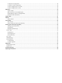
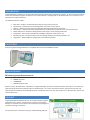
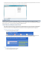
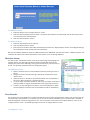
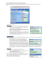
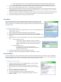
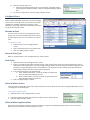
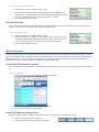
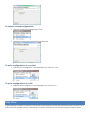
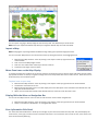
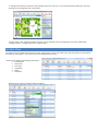
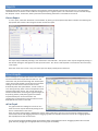
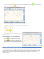
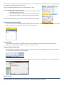
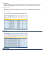
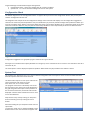
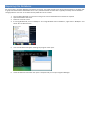
Contents Introduction ........................................................................................................................................................................ 4 Controllers ........................................................................................................................................................................... 4 Requirements ...................................................................................................................................................................... 4 Minimum System Requirements ............................................................................................................................................. 4 Connect ............................................................................................................................................................................... 4 Add a New Connection ............................................................................................................................................................ 5 Ethernet Connection ............................................................................................................................................................ 5 Modem Connection ............................................................................................................................................................. 5 Serial Port Connection ......................................................................................................................................................... 6 Edit a Connection ..................................................................................................................................................................... 6 Delete a Connection ................................................................................................................................................................ 6 Data Synchronization ............................................................................................................................................................... 6 Changes made from the controller's panel ......................................................................................................................... 6 Changes made in the software while connected ................................................................................................................. 6 Changes made in the software while off line ...................................................................................................................... 6 System Configuration .......................................................................................................................................................... 6 Controller Configuration .......................................................................................................................................................... 7 Operational Settings Tab ..................................................................................................................................................... 7 Factory Settings Tab............................................................................................................................................................. 7 Controller Time Tab ............................................................................................................................................................. 8 Central Control Settings Tab ................................................................................................................................................ 8 Site Name Tab ...................................................................................................................................................................... 9 Advanced Tab ...................................................................................................................................................................... 9 Configure Devices .................................................................................................................................................................. 10 Install, Remove and Replace System Devices .................................................................................................................... 10 Moisture Sensor................................................................................................................................................................. 11 Zone Decoder..................................................................................................................................................................... 11 Flow Meter ........................................................................................................................................................................ 13 Pressure Meter .................................................................................................................................................................. 13 Rain / Freeze Sensor .......................................................................................................................................................... 14 Water Source ..................................................................................................................................................................... 14 Configure Zones ..................................................................................................................................................................... 15 Rename a Zone .................................................................................................................................................................. 15 Select a Zone Type ............................................................................................................................................................. 15 Soak Cycle .......................................................................................................................................................................... 15 Select a Water Source ........................................................................................................................................................ 15 Select a Watering Restriction ............................................................................................................................................ 15 Select a Flow Rate .............................................................................................................................................................. 16 Manual Programs................................................................................................................................................................... 16 Create and Edit Manual Programs ..................................................................................................................................... 16 Insert/Edit Manual Program Steps .................................................................................................................................... 16 Copy/Paste Manual Program Steps ................................................................................................................................... 17 Delete Manual Program Steps ........................................................................................................................................... 17 Run/Stop Manual Programs .............................................................................................................................................. 17 Event Pause............................................................................................................................................................................ 17 Create and Edit Scheduled Events ..................................................................................................................................... 17 Delete Scheduled Events ................................................................................................................................................... 18 Water Restrictions ................................................................................................................................................................. 18 Create and Edit Watering Restrictions............................................................................................................................... 18 Export, Import and Print Configurations ............................................................................................................................... 18 To export the configuration ............................................................................................................................................... 18 To import a saved configuration ........................................................................................................................................ 19 To print configurations to a printer ................................................................................................................................... 19 To print configurations to a file ......................................................................................................................................... 19 Map View .......................................................................................................................................................................... 19 Import a Map ..................................................................................................................................................................... 20 Move Zone Icons on the Map Display ............................................................................................................................... 20 Display/Hide the Menu or Navigation Bar ......................................................................................................................... 20 Zone Information Side Panel ............................................................................................................................................. 20 System View ...................................................................................................................................................................... 21 Reports .............................................................................................................................................................................. 22 View a Report .................................................................................................................................................................... 22 Zone Graphs ...................................................................................................................................................................... 22 Edit a Graph ....................................................................................................................................................................... 22 View Temperature and Soil Conductivity .......................................................................................................................... 23 Working with Controller Logs (Data).................................................................................................................................. 23 Viewing only selected Data ................................................................................................................................................ 24 Sorting Data ....................................................................................................................................................................... 24 Navigating the data logs .................................................................................................................................................... 24 Sensor Logs ............................................................................................................................................................................ 24 Soil Moisture ...................................................................................................................................................................... 25 Soil Temperature ............................................................................................................................................................... 25 Soil Conductivity ................................................................................................................................................................ 25 Error Logs ............................................................................................................................................................................... 25 Watering Logs ........................................................................................................................................................................ 25 Exporting Data ....................................................................................................................................................................... 26 To export data ................................................................................................................................................................... 26 To repair log data ............................................................................................................................................................... 26 Diagnostics ........................................................................................................................................................................ 26 Configuration Check .............................................................................................................................................................. 27 System Test ............................................................................................................................................................................ 27 Firmware Upgrade ............................................................................................................................................................. 28 Repairing the Database ..................................................................................................................................................... 29 Introduction Irrigation Manager™ Software is an advanced software package designed for professional irrigators. It allows remote monitoring and control of multiple irrigation controllers from a central location. Anything that can be done directly on a controller can be done with the software remotely. The software features include: Map View – Display a customized system layout using a map of your site System View - View the status and configuration of all zones in your system Reports – Advanced system reporting capabilities with detailed watering information Zone Graphs - Graph soil moisture, temperature and conductivity from actual sensor measurement data Water Restrictions – Restrict watering based on site usage or local watering ordinances Event Pause - Event pause capabilities for weddings, ball games, family picnics, etc. Manual Programs - Configure custom manual watering sequences for testing, blowouts, etc. Diagnostics – Quickly diagnose configuration and electrical problems Controllers Acclima Irrigation Manager Software is compatible with the Acclima CS3500 controller. Requirements Minimum System Requirements Microsoft Windows XP, Windows Vista or Windows 7 operating systems 800MHz processor 512MB RAM 50 MB hard drive space When running in Windows Vista or Windows 7, Irrigation Manager must be run with administrator permissions. This is done by right clicking the shortcut and selecting “Run as Administrator”. For a more permanent solution, right click the shortcut and select Properties. Under the Compatibility tab place a checkmark next to the “Run this program as an administrator” option and click the OK button. Connect Irrigation Manager Software allows you to manage multiple irrigation controllers from a central, remote location. The first time Irrigation Manager is launched, the connection wizard will walk you through the process of creating a connection. You may connect to a controller using any of the following methods: Serial Port – This requires a standard serial cable or USB-to-serial cable. The cables are not included. Telephone/Modem – This requires an analog phone line. Internet/Ethernet – This requires an ethernet adapter which is not included. You may add as many controller connections as you wish. Each connection is saved and is easily accessible at any time from the Connection list. However, only one controller can be connected at a time. Once you connect to a controller, the connection name that you provided will be overwritten with the controller's actual name as it is specified in the controller. The controller’s system identification number will also be saved and displayed in the connection list. Connect Simply double-click on the controller you wish to connect to. Alternately, you may select the controller and click the “Connect” button. This will initiate the connection to the controller and download all of its data to the computer. This may take an extended period of time depending on the speed of your connection and the amount of data on the controller. Subsequent connections will only download the data that has been logged since the last connection from this computer and will likely complete more quickly. Once the connection is established and the synchronization is complete, any changes you make in the software will be reflected in the controller. It is as if you are literally at the controller. View Offline You may also view the controller's information offline, without connecting to the controller. Simply select the controller and click the “View Offline” button. This will display all controller information as of the last successful connection. You will not be able to modify any settings on the controller since you are not connected. Add a New Connection You may connect to a controller in multiple ways. Ethernet Connection 1. 2. 3. 4. 5. 6. Click the “New Connection” button. Enter the Site Name. Click on “Ethernet”. Enter a hostname or IP address Enter a Host Port number. Click the “Connect” button. Modem Connection 1. 2. 3. 4. 5. 6. Click the “New Connection” button. Click on “Modem”. Enter the Site Name. Select a modem from the drop-down list. Enter the telephone number for the controller. To add a short time delay, insert a comma in the number. Enter user name and password. 7. Click the “Save” button if you want the user name and password to be saved, otherwise click the “Connect” button. Serial Port Connection 1. 2. 3. 4. Click the “New Connection” button. Click on “Serial Port”. Select the appropriate serial port from the dropdown list. Click the “Connect” button. Edit a Connection You can edit any of the connection properties at any time. 1. 2. Select the desired controller to edit. Click the “Edit” button. Make the desired changes and click the “Save” button. Delete a Connection You may delete a connection to a controller by doing the following: 1. Select the desired connection to delete. 2. Click the “Delete” button. Data Synchronization The controller stores information about your system in the form of logs. These logs include information gathered from the controller and sensors. Logs are stored in the controller for up to six months. After six months the older logs are replaced by the newer logs. Each time you connect to a controller using Irrigation Manager, the controller's data is downloaded to your computer. This is known as data synchronization. Even though the controller is limited in the amount of data it can store, your computer is not. It will store all synchronized data that was downloaded from the controller and will never overwrite any data. It is important to connect to your controller frequently to keep your computer up to date. Changes made from the controller's panel When you modify the settings on the controller from its control panel, the changes are recorded in its memory and will synchronize with the software the next time you connect. Irrigation Manager will show the new changes you made to the controller. Changes made in the software while connected When you modify the settings on the controller from Irrigation Manager, while connected to the controller, the changes are instantly saved to and reflected in the controller. It is as if you are making the adjustments at the controller. Changes made in the software while off line While viewing the controller in Offline mode in Irrigation Manager, you can modify its configurations. These changes will be updated in the controller the next time you connect. System Configuration The controller must be configured before it can be used. Configuration involves setting up devices such as moisture sensors, flow meters, zone adapters and water sources, and assigning these devices to zones. In order to properly configure the system, you must first configure the devices and then configure the zones by assigning the devices to zones. Controller Configuration Configuring the controller allows you to edit general controller settings. These include Central Controller Settings, modem settings, clock, etc... To configure the controller select “Configure>Controller Configuration…” from the file menu. Operational Settings Tab Max Zones Watering Simultaneously This field adjusts the number of zones that are allowed to water simultaneously. Although the maximum value is four, the actual number will depend on the individual flow rates of the zones, the water management settings, etc. Valve Delay/Flow Setting Most systems have a delay between the time the valve opens and the time water begins to flow. Use this setting to adjust the valve time delay from 1 to 999 seconds. Minutes between sensor log readings This field adjusts the time between moisture sensor log readings. It can be adjusted from 5 to 60 minutes. Factory Settings Tab Factory/Calibrations settings are displayed here. Factory settings should not be modified unless directed by an Acclima technician. Controller Time Tab The functions within the controllers are monitored by an internal clock. This screen allows for adjustment of the controller's internal clock as well as synchronization between your computer's clock and the controller's clock. The controller’s clock can be set in two different ways 1. 2. Synchronizing with the computer's clock Manually entering the time Central Control Settings Tab The Central Control Settings window allows you to adjust the central control communications settings on the controller. The controller includes a modem and is capable of communicating with computers running Windows® operating systems. You can define modem answering restrictions to limit when the controller modem will answer. For example, if the controller shares a telephone line with a business office, you can define restrictions that allow the modem to only answer after business hours. Modem Answering Restrictions You can disable or enable the modem's answering feature by clicking on “Modem Answering Enabled”. Click on “Restricted Answering Times” to display and customize the Hourly Restriction schedule. You can modify the schedule by clicking the desired cells in the grid. Green cells indicate times the modem will answer or are unrestricted. Blue cells indicate times the modem will not answer. Login Accounts You can create up to 3 login accounts. Each account consists of a name and password. Site Name Tab This window allows you to enter information about you irrigation site, such as name, address and phone number. Advanced Tab The advanced screen is for factory use only. You should not make any adjustments to any of the information on this screen. These setting should not be modified unless directed by an Acclima technician. Configure Devices All devices installed on the system are displayed by category. This includes moisture sensors, zone adapters, flow meters, pressure meters, and water sources. After a device is configured it can be assigned to a zone. You may Add, Remove and Replace devices from this menu. You may also view and modify the configuration of any. Install, Remove and Replace System Devices Once a device is physically installed in or removed from the irrigation system on your site, it must also be installed/removed in the software. Be sure not to change configurations on the software without first making the changes on the controller and vice versa. Devices can be reconfigured if you have made errors or wish to change the controller’s configuration. To install a moisture sensor or zone adapter 1. Click the “Install System Devices” button. 2. Enter the serial number of the device and click “Detect By Serial Number”. Serial numbers are inscribed on the device. Zone adapters contain many serial numbers (see the CS3500 installation guide for details). To add a water source 1. 2. Click the “Install System Devices” button. Click the “Add Water Source” button. To remove a device 1. 2. 3. Select the device in the “Configure Devices” screen. Click the “Remove System Devices” button. The system device options are listed along with all other devices that are connected to the selected device. Click the “Remove Device” button. To replace a device 1. 2. 3. Select the desired device to be replaced. Click the “Replace Device” button. Enter the serial number of the newly installed device and click the “Replace Device” button. All configured settings for the old device will be transferred to the new device. Only use the “Refresh Addresses” button if additional devices are added that may have been used in a different system. The controller will refresh all the device addresses to ensure there are no conflicting addresses. Moisture Sensor ® The Acclima TDT Soil Moisture Sensor is the key to maintaining and managing your irrigation system. The data logs and information they provide will enable you to manage your system more efficiently, saving you time and money. For the sensor to do this, it is extremely important that it be configured properly. To configure sensors 1. 2. 3. 4. 5. Select a moisture sensor to view the device options by clicking its name in the list. Change the sensor name by entering a descriptive name/location in the “Name” field. Select the sensor’s “Host Zone” from the drop-down list. The Host Zone is the zone in which the sensor is physically located. To set the upper and lower thresholds, click the up and down arrows of the respective fields or drag the threshold lines on the graph with the mouse. To take a current reading from the sensor, click the “Read Sensor” button. This will display the moisture level, soil temperature and soil conductivity. Zone Decoder The controller uses zone decoders to communicate with the solenoid valves throughout the system. Each solenoid must be routed through a zone decoder or soil moisture sensor in order to function effectively. Once a zone decoder is installed, it must be configured, named and assigned to a zone. This can be done in the either the “Configure Devices” screen or the “Configure Zones” screen. The following example will use the “Configure Devices” screen. To configure a zone 1. 2. 3. In the “Configure Devices” screen, select the zone to rename. Enter a descriptive name for the zone in the “Zone Name” box. Select a zone type from the “Zone Type” drop-down list. The configuration options are dependent on the zone type. There are three zone types. Sensor Zone A Sensor Zone is a zone that is controlled entirely by a moisture sensor. a. Select a sensor from the “Moisture Sensor” drop down list to link the zone with its respective sensor. b. Enter the “Sensor Zone Percolation Time” in hours. In soils with high clay content, water absorption is slow and a delay time may be set to allow water to settle. c. Enter the “Maximum Water Duration” time in minutes. If water on demand is desired, set the duration to a high value. If timed cycles are desired, click the “Show Thresholds” button and set the “Upper Threshold” to a high value. Dependent Zone A Dependent Zone is a zone that is controlled by the sensor of a sensor zone. It is set to run as a percentage of the sensor zone run time. a. Select a zone from the “Sensor Zone” drop down list. This links the zone with a sensor controlled zone. Select the Sensor Zone that is physically closest to the Dependent Zone or has soil properties most similar to the Dependent Zone. b. Enter the “Dependent Zone Tracking Ratio (%)” in percentage points. This ratio is the amount of water this zone will receive compared to the Sensor Zone. This ratio is necessary to adjust for differing varieties in the rate water is applied by differing emitters. For example, a dependent zone with an application rate of 10 Gallons per Minute (gpm), that is tracking a sensor zone with an application rate of 20 gpm, will need a tracking ratio of 200% to ensure adequate irrigation of the dependent zone. Timed zone 4. A Timed Zone runs as a conventional timer based zone. a. Enter the “Time Between Water” in hours. This is the number of hours between watering cycles. b. Enter the “Watering Duration” in minutes. This is the maximum length of time for a watering cycle. Check or uncheck the box titled “Use Soak Cycling”. Soak Cycling simply waters for a period of time then waits to soak before continuing to water, all during a single watering event. If you enable Soak Cycling, do the following: 5. 6. 7. 8. a. Enter “Water-On Duration”: This is the number of minutes the zone will water before waiting to soak. b. Enter “Soak Duration”: This is the number of minutes the zone will soak before watering continues. Select the appropriate water source from the “Water Source" drop-down list. If your system has only one water source and is using the default water source, "<Unassigned>" will be displayed. Select the appropriate watering restriction from the “Watering Restriction” list. This enables the zone to operate independently of the system. You must create a watering restriction before it can be assigned to a zone. You may modify the restriction by clicking on the "Edit..." button. Enter the “Flow Rate” in Gallons per Minute (gpm). If your system has a flow meter it will automatically assign flow rates to each zone as it waters. If you are not using a flow meter, it is not necessary to indicate a flow rate. To save the configuration, click the “Apply Changes” button. Flow Meter Flow meters allow the controller to monitor flow rates for zones and the system. Flow meters enable the system to maximize efficiency by automatically managing the water usage. If a flow meter is installed the Acclima Irrigation software can measure the flow rate at the flow meter. To configure the flow meter 1. 2. 3. 4. 5. 6. 7. Select the flow meter in the “Configure Devices” screen. It will be displayed in the “Other Devices” section. Enter a descriptive name for the flow meter in the “Name” box. Select a water source from the “Attached to Water Source” drop-down list. Select the appropriate pipe diameter from the “Pipe Diameter/ Flow Meter” dropdown list. If your flow meter is not in the drop down list, you may enter custom settings by clicking on the “Custom Settings” tab. a. Enter the “KFactor” value. i. The “KFactor” equals the gallons per pulse of your flow meter multiplied by 60. ie: KFactor=(Gallons per Pulse)*60 The minimum KFactor is 0.002. The maximum KFactor is 100. b. Enter the “Offset” value. i. Many flow meters do not use an offset. If the documentation of your flow meter does not specify an offset it should be set to 0. To save the configuration, click the “Apply Changes” button. Readings are taken and displayed by clicking the “Flow Reading…” button. Pressure Meter Pressure meters work in conjunction with flow meters to monitor the water pressure in your system. They are helpful for diagnosing problems such as broken sprinkler heads, broken pipes and other flow problems. You can set warning levels to allow the system to either warn you or shut down if the pressure gets too high or too low. To configure pressure meters 1. 2. 3. 4. 5. 6. 7. Select the pressure meter in the “Configure Devices” screen. It will be displayed in the “Other Devices” section. Enter a descriptive name for the pressure meter in the “Name” box. Select a water source from the “Attached to Water Source” drop-down list. Enter the “High Pressure Threshold” in psi. Enter the “Low Pressure threshold” in psi. To save the configuration, click the “Apply Changes” button Pressure readings are taken and displayed by clicking the “Pressure Reading…” button. Rain / Freeze Sensor A Rain / Freeze sensor detects freezing temperatures and suspends watering. A separate rain sensor or wind sensor can also be connected, allowing irrigation control due to current rain and wind conditions. To configure rain / freeze sensor 1. 2. 3. 4. Select the “Configure>Controller Configuration…” menu. Select the “Operational Settings” tab. Select the “Flags” tab. Enable or disable the switches by clicking on “Enable Freeze Sensor” and “Enable Rain Sensor”. 5. 6. Select the rain / freeze sensor in the “Configure Devices” screen. It will be displayed in the “Other Devices” section. Enter a descriptive name for the sensor in the “Name” box. 7. 8. To save the configuration, click the “Apply Changes” button. Readings are taken and displayed by clicking the “Read Sensor” button. Water Source All systems have a water source. Irrigation Manager defaults to a single constant source. If your system only has one water source you may choose to use the default setting. However, if your system has multiple water sources, two mains or some other configuration, you need to configure each water source and assign zones to each source. To configure a water source 1. 2. 3. 4. 5. 6. 7. Select the water source in the “Configure Devices” screen. It is displayed in the “Water Sources” section. Enter a descriptive name for the water source in the “Name” box. Enter the “Minimum Flow Rate” for the water source. If the value is not known, leave default factory settings. Enter the “Maximum Flow Rate” for the water source. If the value is not known, leave default factory settings. Enter the “Valve Current” by clicking the “Test…” button. Assign zones to the water source by clicking the “Assigned Zones…” button. Select the water source and the zones to be assigned to that water source. Zones that are not assigned to the selected water source will not be highlighted. Zones that are assigned to the selected water source will appear with a green highlight. Zones that are not assigned to any water source will appear in red. 8. 9. Select the “Switch Type” tab. a. Select the appropriate switch type. If “Pump Switch” is selected and the pump supports a backflush switch, check the “Supports Backflush Switch” box To save the configuration, click the “Apply Changes” button. Configure Zones Irrigation systems are grouped into zones controlled by valves. Irrigation Manager allows you to view and manage all the zones in one easy to use screen. Each zone may be configured or updated as desired. Zone types, sensor selection, soak cycling, water source and water restrictions are all chosen from this screen. Rename a Zone A zone’s name is critical to the management of your system. The names should reflect the zone's location, sprinkler type or both. You can rename a zone at any time. To rename a zone 1. 2. 3. Select the zone in the “Configure Zones” screen. Enter a descriptive name in the “Name” box. Click the “Apply Changes” button Select a Zone Type Refer to “Zone Decoder” in the “Configure Devices” section above. Soak Cycle 1. 2. 3. 4. Select the zone in the “Configure Zones” screen. Check or uncheck the box titled “Use Soak Cycling”. Soak cycling simply waters for a period of time then waits to soak before continuing to water, all during a single watering period. This is especially useful when irrigating a zone located on a slope, allowing the water to soak before it runs off. While a zone is soaking the system will use the time to water another zone then return to the soaking zone. If you enable Soak Cycling, do the following: a. Enter “Water-On Duration”: This is the number of minutes the zone will water before waiting to soak. b. Enter “Soak Duration”: This is the number of minutes the zone will soak before watering continues. Click the “Apply Changes” button. Select a Water Source Each zone must be assigned a water source If your system has only one water source and is using the default water source, “<Unassigned>” will be displayed. To assign a water source 1. Select the zone in the “Configure Zones” screen. 2. 3. Select the appropriate water source from the “Water Source” drop-down list. Click the “Apply Changes” button. Select a Watering Restriction Each zone can be assigned a watering restriction enabling it to operate independently of the system. You must create a watering restriction before it can be assigned to a zone. To assign watering restrictions 1. Select the zone in the “Configure Zones” screen. 2. Select the appropriate watering restriction from the “Watering Restriction” drop-down list. This enables the zone to operate independently of the system. You may modify the restriction by clicking on the "Edit..." button. Click the “Apply Changes” button. 3. Select a Flow Rate If your system has a flow meter is will automatically assign flow rates to each zone as it waters. If you are not using a flow meter, it is not necessary to indicate a flow rate, use the default rate. To specify the flow rate 1. 2. 3. Select the zone in the “Configure Zones” screen. Enter the “Flow Rate” in Gallons per Minute (gpm). If your system has a flow meter it will automatically assign flow rates to each zone as it waters. If you are not using a flow meter, it is not necessary to indicate a flow rate. Click the “Apply Changes” button. Manual Programs Irrigation Manager allows you to configure custom watering sequences that can be executed manually. Each program includes one or more steps that water or pause a zone for a specified duration. You can create programs to run tests on sprinkler heads (walk around tests). Or you can create a flush program to run all zones for a several minutes when you apply fertilizer. This powerful tool can be run at the controller or remotely from Irrigation Manager. Create and Edit Manual Programs You can create manual programs that are customized for your specific needs. First you must add a program to the program list. To add a program 1. Create a manual program by clicking the “Add Program” button. 2. 3. Enter a descriptive name in the “Program Name” box. Click the “Save” button to save changes. Insert/Edit Manual Program Steps Once the program has been created, you can insert steps or commands for the controller to perform. 1. 2. Select a program from the “Program” list. Click the “Insert Step” button to create a new step. 3. 4. 5. 6. Select the desired action in the “Step Action” list either “Pause Watering” or “Water Zone“. Select the zone to water by clicking on the arrows to cycle through zone numbers. Or click on the "..." button to display a list of zones to choose from. The zone name is displayed in red. Enter a “Step Duration” using the up/down arrows. Click “Save” to save changes. Copy/Paste Manual Program Steps To speed up the creation of a manual program, you can copy and paste existing steps. This allows you to rapidly fill in the actions and then make minor changes like name and duration. 1. Select a program step. 2. Click the “Copy Step” button. 3. Select the step above the desired location and click the “Paste” button. 4. Click “Save” to save changes. Delete Manual Program Steps 1. 2. 3. Select a program step. Click the “Delete Step” button. Click “Save” to save changes. Run/Stop Manual Programs You can run the manual programs from the controller panel or remotely from the software. 1. 2. 3. Select a Program. Click the “Start Program” button to begin running the program. Click the “Stop Program” button to stop the program. Event Pause You may schedule up to 6 events that temporarily pause the entire system. This is particularly helpful for special occasions such as parties, ball games, family picnics etc. Scheduled event dates, times and durations are all set in this screen. Create and Edit Scheduled Events 1. Create a pause event by clicking on a day in the calendar view or by selecting a scheduled event in the “Pause Events” list on the left side of the screen. 2. Specify the “Water-Off Date” by clicking a date in the “Water-Off Event” window. 3. 4. 5. 6. Specify the “Water-Off Time” by entering the hour, minute and AM/PM. This can also be done with the up/down arrows. Specify the duration in the “Pause System Watering” section by entering the days, hours and minutes or by using the up/down arrows. The pause and resume dates and times are displayed in orange. Enter a descriptive name in the “Event Description” box to distinguish the event from other events. Click “Save” to save and close Water-Off Event window. Delete Scheduled Events 1. 2. 3. Select a pause event by clicking on an event in the calendar view or by selecting a scheduled event in the “Pause Events” list on the left side of the screen. Click the “Delete” button at the bottom of the “Water-Off Event” window. Close the “Water-Off Event” window. Water Restrictions Sensor zones are programmed to water as needed to keep a healthy lawn. However, there are times when the controller should not be allowed to water. This might include the hottest hours of the day or when local watering restrictions prohibit watering. These times can be programmed in the “Water Restrictions” screen to prohibit your system from watering during inappropriate times. Watering restrictions are divided into profiles and are listed in the “Restriction Name” list. These profiles may be shared by zones that will be watered similarly. For example, if there is an activity every Friday night, you could create a restriction that would prohibit watering on Friday nights from 4pm to 10pm. Then you would assign this restriction to the zones where the activity will take place. Other restrictions might exist to water at the same time but only on the unused zones. Create and Edit Watering Restrictions 1. 2. 3. 4. Select a restriction from the “Restriction Names” list. Select seasonal restriction. Year-round watering will water with the same restrictions throughout the entire year. Seasonal watering is requires a start and end date. Select a “Daily Restriction” by clicking on the red underlined “everyday” link. Daily restrictions may be set to everyday, even days, odd days, every other day or up th to every 10 day. Hourly restrictions are displayed in the "Hourly Restriction" grid and may be set for half hour intervals throughout each day of the week. Changes may be made by clicking a half hour block or by dragging the mouse across consecutive blocks. A green block indicates that watering is allowed. A blue block means that watering is restricted. Click on any block or range of blocks to toggle its color and therefore its watering restriction status. Export, Import and Print Configurations The configuration of your controller is vital to efficiently managing your irrigation systems. It is important to protect the configurations you have created. You can export, import and print your controller’s configurations. This is helpful when replacing controllers. To export the configuration 1. Select the “Export Configuration” screen. 2. Specify a location to save the configuration. To import a saved configuration 1. Select the “Import Saved Configuration” screen. 2. Specify the location of the configuration to be imported. To print configurations to a printer 1. Select the “Print Configuration” menu followed by the “To Printer” menu. To print configurations to a file 1. Select the “Print Configuration” menu followed by the “To File” menu. Map View Irrigation Manager is capable of importing a map of each site that allows you to show the approximate physical location of each of your zones. This provides you with a clear view of your system and enables you to visually manage your irrigation system. You can import any jpeg or bitmap image file into the map view. The default map is shown above. NOTE: Once your replace the default map with your image the default map cannot be recovered. Import a Map NOTE: Changing the map image deletes the default image making the imported image permanent. You can move the “Map Controls” box around the screen by clicking the blue bar and dragging the box. 1. 2. 3. 4. Maximize the “Map Controls” menu by clicking on the square at the top right hand corner of the window. Click on the “Load Map Image” button. Click the “Yes” button when asked if you want to continue. Locate the map image and click “Open”. Move Zone Icons on the Map Display To visually recreate your irrigation site in the map view you can drag each of your system's zones and water sources to their appropriate locations on the map. Irrigation manager uses icons to represent each zone or water source. Once the icons are positioned, they can be locked in place. To place icons on your map 1. 2. 3. 4. Maximize the “Map Controls” menu by clicking on the square at the top right hand corner of the window. Uncheck the “Lock Zone Icons” box. Moving the mouse pointer over an icon will display the zone's description. Click and hold on the desired zone and drag it to the desired location. When all zones have been moved to the desired locations, check the “Lock Zone Icons” box. Display/Hide the Menu or Navigation Bar You can use the “Map controls” menu to show or hide the main menu and the navigation bar. 1. 2. Maximize the “Map Controls” menu by clicking on the square at the top right hand corner of the window. Check or uncheck the “Show Menu” or “Navigation Bar” boxes. Zone Information Side Panel The “Zone Information Side Panel” allows you to manage all your zones from within the map view. The panel displays the zone's status, name, type, moisture sensors and water restrictions. You can test the zone's valve current, read a sensor and even initiate manually watering. To manage zones from the map view, simply double click on the zone's icon. The “Zone Information Side Panel” will open, allowing you to manage the zone's information. A similar panel is also used when configuring zones. You can adjust the zone's configuration from within “Map View”, “Configure Zones”, “Configure Devices” or “System View”. System View The system may be viewed and monitored from the “System View” screen. This allows you to see the system's current status to be viewed at a quick glance. The zones may also be managed from this view. “System View” displays the following information: Zone Number Zone Name Zone Type Type Detail Status Exceptions Double Click on a zone to view and edit its properties. Reports Watering information is recorded and stored in the controller and transferred to any PC that connects to it. The information collected from the controller is vital to efficient management your irrigation system. This information may be accessed through the “Reports” screen. Total water, water cycles and manual watering information is available for each zone. View a Report To run a report, select the “Start Date” and “End Date” by clicking on the respective drop down calendars and selecting the appropriate date. Click the “Run Program” button to view the report. The report may be edited by selecting a new “Start Date” and “End Date”. The report's colors may be changed by clicking on the colored rectangle in the legend near the top of the screen. The “Zoom” slider expands or contracts the size of each day in the report. Hover the mouse over a zone or any part of the report to display a description of that item. Zone Graphs Sensor readings are recorded and stored in the controller and are transferred to any PC that connects to it. This information may be accessed through the “Zone Graphs” screen. Zone graphs enable a visual view of soil moisture readings. You can see the moisture level increase dramatically when the system waters, as well as when it rains. During the day, water in the soil evaporates and at night the evaporation ceases. This is easily seen as the moisture level flattens out during the night and begins to drop during the day. Study these graphs to be better acquainted with your soil characteristics. Soil conductivity, soil temperature and soil moisture can be displayed for each sensor in this view. Edit a Graph The graph shows the readings for one sensor at a time. The sensor may be selected by clicking on the sensor at the bottom of the screen. Zoom in and out of the graph b y dragging the “Zoom” slider to the left or right. You can also zoom by holding the right mouse button down and dragging the mouse. Dragging up/down will expand/contract the vertical axis. Dragging right/left will expand/contract the horizontal axis. You can pan the graph by holding the left mouse button down and dragging the mouse. Dragging up/down will move the graph vertically. Dragging to the right/left will move the graph horizontally. To re-center data, click the button. To display controller initiated watering cycles, click initiated watering cycles, click the and to display manually button. The blue dots on the graph indicate a controller initiated watering cycle. To view details about the watering, cycle place the mouse arrow over the blue dot. A yellow box appears displaying the start time and duration of the watering cycle. View Temperature and Soil Conductivity Press the button to view the temperature graph. Press the button to view the soil conductivity graph. These two graphs appear above the soil moisture graph. As you adjust the soil moisture graph the temperature and soil conductivity graphs will adjust to match the format of the soil moisture graph. Working with Controller Logs (Data) Each time you connect to a controller using Irrigation Manager, data stored on the controller is downloaded to your PC. This includes all configuration data and all logs that have been stored since the last complete download to your PC. The controller has sufficient internal memory to archive data logs for six months after which the oldest data will be overwritten by new data. However, once you synchronize the controller logs with Irrigation Manager, the data logs remain permanently on your computer’s hard drive. The controller stores the raw data from sensors, flow meters, pressure meters, and other installed devices. It also stores system error information and watering cycle information. The logs are viewed by selecting the “View > Controller Logs…” menu. Irrigation Manager displays three types of logs: 1. Sensor Logs - displays all sensor measurement readings that have been downloaded from the controller. 2. Error Logs - displays all errors that have occurred on the controller. 3. Watering Logs - displays all automatic and manual watering activity. Click on the tabs near the top of the screen to move between the three log types. Viewing only selected Data You can limit the amount of data displayed by specifying a filter. Each column can be filtered. To specify a filter, click on the down arrow button in the column header and select the item to display. Sorting Data To sort data in each column, click anywhere on the blue column header. The data will now be sorted by that column heading. Clicking the header again will sort the column in the reverse order. Navigating the data logs The navigation bar is located at the bottom of the screen. Use the arrows in the navigation bar to move around in the grid. You can also use the arrow keys on your keyboard. You can also create advanced data filters by selecting the “Filter” button which is the right most icon on the navigation bar. Sensor Logs ® The controller uses Acclima Digital TDT Soil moisture sensors to measure soil moisture content. The sensors also measure and log soil temperature and soil conductivity. Sensor data can be viewed in the sensor logs window. Soil Moisture Each sensor connected to a controller regularly measures and records soil moisture based on volumetric water content (VWC). This number is represented as a percentage of total water content. A reading of 25% means that in any given volume of soil, 25% of it is water. Soil Temperature Soil temperature is measured and recorded in the system. Temperature can be displayed in degrees Celsius or degrees Fahrenheit. Soil Conductivity The sensor also measures and records soil conductivity displayed in dS/m. Error Logs When the system encounters an error the information regarding the error is logged and can be viewed in the error logs window. Watering Logs All watering activity is recorded in the watering logs window. Exporting Data The data collected by your controller is extremely valuable for managing your system's efficiency. You may wish to export the data into other programs allowing greater flexibility and analysis of the data. You can export all logs into other programs such as Microsoft Excel. To export data Click on the “Export Watering Logs…” button near the top of the screen. You must then specify the name and destination of the log file. All logs are exported in Comma Delimited (*.csv) format. Click Save to save the file. To repair log data If a controller's clock has been set incorrectly, it is possible to get duplicate logs and logs whose date is in the future. To correct this, click on the "Repair Logs" button near the top of the screen. Diagnostics The "Diagnostics" screen helps you quickly troubleshoot your system. Irrigation Manager has two different types of diagnostics: 1. Configuration Check - check your configuration for common problems. 2. System Test - run a series of electrical diagnostic tests on the system. Configuration Check The default diagnostic is the “Configuration Check”. It appears when you click on the "Diagnostics" button, but you may also click the “Configuration Check” tab. This diagnostic tool analyzes all of the configuration settings of the controller and displays a list of configuration suggestions. These do not necessarily indicate problems. They are intended only to point out potential configuration problems of which you may not have been aware. Notice in the picture below that zones 4, 6 and 8 are disabled. This is a potential problem since those zones will not water. However, they may also be intentionally disabled. It is the responsibility of the user to determine if the suggestions in the list need to be acted upon. Configuration suggestions are grouped by type as noted in the "Type" column. Each type has a number which uniquely identifies it in the group. This is contained in the "#" column. This could be its zone id or restriction id, etc. The "Description" column displays the potential problem. More details may be provided in the "Details" column. System Test The “System Test” diagnostic tool runs a series of electrical diagnostic tests on the system. It has a basic and advanced mode. Click the "System Test" tab to access this tool. The basic mode requires no user input. It will test all zones and devices and report any errors. Click “Start Test” to run in basic mode. The progress of the test is indicated by a bar across the top of the screen. Each error will be displayed in the grid along with a description of the problem. At the conclusion of the test, the overall status will be displayed. A failure status indicates that one or more errors were detected. Stop the test at any time by clicking on "Stop Test". Print the resulting errors by clicking the “Print” button. Advanced mode gives you complete control over the system test. To enter this mode, click on "Advanced Mode" at the bottom of the screen. A check mark will appear next to it. In this mode, you may specify which devices to include in the test and what tests to run. Place a check mark next to each device filter category you would like to have access to. This adds all members of the selected category into the “Devices” list. You may further refine your filter to include only a subset of devices in the list. To do this, hold down the Control button on your keyboard and with your mouse select the devices you want to test. You may also select the types of tests to run. These include: Valve Current, Sensor Readings, System Current and Error Rate. Click the “Run Test” button to begin testing. You may stop the test at any time by clicking the “Stop Test” button. In this example above: Devices 7 and 8 are selected for testing Zones 2 and 3 are selected for testing There was a “2-wire Communication Failure” while reading valve current on zone 2 and 3. Device 7, which is a moisture sensor, failed to take a reading. Device 8, which is a moisture sensor, read 0% water The system current values were 0mA, 5mA and 0mA. The error rate test is still running (see the orange progress bar). So far the test succeeded 15 times and did not receive a response 43 times. At the completion of the test, the sum of the five Error Rate rows will equal the number of devices selected (4 in this case) multiplied by the number of times the error rate test was set to run (50 in this case). In advanced mode, there is no overall system pass or fail. The result of each test is displayed. The user must determine whether the result is a problem or not. Firmware Upgrade Firmware is the software that runs inside the controller. Occasionally, new features are added to the controller by upgrading to a new firmware version. When a new firmware version is available, it is typically bundled with an updated version of Irrigation Manager. After installation of a new Irrigation Manager version and after successfully connecting to a controller, you may see the following screen: You may also perform an upgrade by selecting the “System>Upgrade Firmware…” menu. Repairing the Database On rare occasions, Irrigation Manager may behave incorrectly. This might include errors during synchronization or not being able to graph data that has been downloaded. This is not a problem with the controller but is typically caused by internal database storage problems on the PC. It can often be easily fixed with no loss of data. 1. 2. 3. 4. Close Irrigation Manager. It cannot be running since it uses the database that needs to be repaired. Open the windows start menu. Select the “Acclima” menu. If running Windows XP, click on “DB Repair”. If running Windows Vista or Windows 7, right click on “DB Repair” and select “Run as Administrator”. 5. Two small windows will appear showing the progress of the repair. 6. These windows will close when the repair is complete and you can open Irrigation Manager.