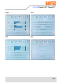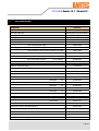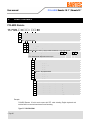
1
POLARIS Remote User Manual Version 4.00 POLARIS Remote 19.1" / POLARIS Remote 15" Type 17-71V2-.... User Manual POLARIS Remote 19.1'' / Remote 15'' Version 4.00 Document No. 11-71V2-7D0011 INDEX A / Status: 7. November 2006 Technical data subject to change! (UK) Ltd. Station Road Facit Whitworth, Near Rochdale Lancashire, OL12 8LJ England Phone: Fax: Email: Internet: +44 17 06 85 22 24 +44 17 06 85 25 21 [email protected] www.bartec.co.uk GmbH Max-Eyth-Straße 16 97980 Bad Mergentheim Deutschland Telefon : Telefax : E-Mail: Internet: +49 7931 597-0 +49 7931 597-183 [email protected] www.bartec.de Contents 1. System description .....................................................................................................................................8 2. Technical data POLARIS Remote ............................................................................................................10 3. 4. 5. 2.1 Characteristics data Remote 19.1'' und Remote 15'' ..................................................................10 2.2 General data...............................................................................................................................10 2.3 Characteristics data Remote 19.1''.............................................................................................11 2.4 Characteristics data Remote 15''................................................................................................12 2.5 Characteristics data keyboard ....................................................................................................13 2.6 Characteristics data mouse, trackball and touchpad ..................................................................14 2.6.1 Mouse ........................................................................................................................................14 2.6.2 Trackball.....................................................................................................................................14 2.6.3 Touchpad ...................................................................................................................................14 Terminal assignment ................................................................................................................................16 3.1 Overview of connections ............................................................................................................16 3.2 Terminal assignment EEx i.........................................................................................................16 3.3 Terminal assignment EEx e........................................................................................................17 3.3.1 Interference suppression............................................................................................................18 Overview of connection diagram.............................................................................................................19 4.1 Standard application – Point-to-Point .........................................................................................19 4.2 Special application – Cascade circuit .........................................................................................19 Notes on the installation of POLARIS Remote .......................................................................................20 5.1 Safety instructions ......................................................................................................................20 5.1.1 Safety-relevant notice.................................................................................................................20 5.2 Maintenance...............................................................................................................................20 5.2.1 Servicing ....................................................................................................................................20 5.2.2 Inspection...................................................................................................................................20 5.2.3 Repair.........................................................................................................................................20 5.3 Installation options......................................................................................................................21 5.3.1 Cable glands / Conduits .............................................................................................................21 5.4 Mechanical installation ...............................................................................................................22 5.4.1 Recommended enclosure...........................................................................................................22 5.4.2 Special installation instructions...................................................................................................22 5.4.3 Cover Ex i terminal box ..............................................................................................................22 5.4.4 General data...............................................................................................................................23 5.4.5 Installation guidelines .................................................................................................................24 Page 5 Contents 6. Installation of additional components.....................................................................................................25 6.1 Local unit for STP cable .............................................................................................................25 6.1.1 Features .....................................................................................................................................25 6.1.2 Operation ...................................................................................................................................26 6.1.3 Mounting arrangement ...............................................................................................................26 6.1.4 Technical data "Local unit" .........................................................................................................27 6.1.5 Compatibility...............................................................................................................................27 6.1.6 The local unit is compatible with the following devices:..............................................................28 6.1.7 Quick Startup .............................................................................................................................29 6.2 Local unit for Fibre optic cable....................................................................................................30 6.2.1 Features .....................................................................................................................................30 6.2.2 Operation ...................................................................................................................................31 6.2.3 Mounting arrangement ...............................................................................................................31 6.2.4 Technical data "Local unit" .........................................................................................................32 6.2.5 Compatibility...............................................................................................................................32 6.2.6 The local unit is compatible with the following devices:..............................................................33 6.3 Connection of EEx i keyboard to the POLARIS Remote ............................................................34 6.4 Connection to BCS 302ex Hand-held scanner ............................................................................34 6.4.1 Supply module for BCS 302ex .....................................................................................................34 6.4.2 Via RS232 ..................................................................................................................................35 6.4.3 Via PS/2 .....................................................................................................................................35 6.5 Display settings ..........................................................................................................................36 6.6 Set up touch screen ...................................................................................................................38 7. Accessories ...............................................................................................................................................39 8. Order numbers ..........................................................................................................................................40 Appendix EC-Declaration of Conformity ................................................................................................41 EG-Baumusterprüfbescheinigung .....................................................................................42-45 EC-TYPE-EXAMINATION CERTIFICATE (Translation) .....................................................46-49 Additional technical information .......................................................................................50-54 - Mounting instructions Class D/E, CAT 6 Outlet - Programming Keyboard wedge - Resistance list - polyester front foil Transport and shipment ..........................................................................................................55 Return processing....................................................................................................................57 Page 7 POLARIS Remote 19.1" / Remote 15" User manual 1. System description POLARIS Remote 19.1'' Keyboard POLARIS Remote 15'' Mouse Trackball Touchpad The POLARIS Remote 19.1" and POLARIS Remote 15" from BARTEC are displays with keyboard and mouse with which a PC in the non-hazardous area can be operated from the Ex zone (Zone 1). Distances are possible up to 10,000 m and depends on the variant. The two POLARIS Remotes provide the user with the facility for use of all PC-based process control systems currently available, without restrictions, in the Ex zone. Page 8 POLARIS Remote 19,1" / Remote 15" The front panel fitting permits easy installation. On request, the devices can also be supplied in the form of complete system solutions in a stainless steel enclosure for wall, floor or ceiling mounted installation. Example: POLARIS Remote with stand Example: POLARIS Remote with Fibre optic The POLARIS Remote 19.1" screen takes the form of a TFT display with SXGA resolution (1280 x 1024 pixels), and XGA resolution (1024 x 768 pixels) in the case of the POLARIS Remote 15". These are notable for their excellent brilliance and extremely good read angle. An intrinsically safe keyboard and mouse, trackball and touchpad are available for front panel installation. Optional it is possible to choose a resistive touch screen (intrinsically safe) or a connection for a hand-held scanner BCS 302ex. Docking-on in the safe area is accomplished via ''local unit'' (included in scope of supply). e.g. Local unit for STP cable Page 9 POLARIS Remote 19.1" / Remote 15" User manual 2. Technical data POLARIS Remote 2.1 Characteristics data Remote 19.1'' und Remote 15'' Type : 17-71V2-.... Ex protection type : e II 2G Ex e q [ib] IIC T4 e II 2D Ex tD A21 IP 6X T 80°C Certification 2.2 : IBExU05ATEX1117 X : Front panel fitting General data Construction System solution in stainless steel enclosure for wall, floor or ceiling mounting Connection to the PC : Connection to VGA, PS/2 keyboard and PS/2 mouse port, RS232 Extension via STP/S cable; 4 x 2 x 23 AWG, optionally via fiber optic cable Requirement to the base station : Keyboard and mouse with PS/2 connector VGA connection or graphics card with the following technical data (DVI connection also possible with fiber optics): - VGA-, SVGA-, XGA-, SXGA resolution - Vertical sync frequency 60 to 75 Hz Transmission distance : Up to 300 m via STP/S cable Up to 400 m via 50 µm multi-mode fibre optic cable Up to 200 m via 62.5 µm multi-mode fibre optic cable Up to 10,000 m via fibre optic cable Power supply : AC 90 to 253 V; 50 to 60 Hz Max. power take-up Pmax : < 60 W Admissible ambient temperature : Storage Operation Material Protection class : : 9 µm single-mode -20 °C to +50 °C 0 °C to +50 °C Front Polyester foil on aluminium sheet (conditionally UV resistant) Enclosure Galvanised sheet steel bichromated IP 65 (front side) IP 54 (rear side) Humidity : 5 to 95 % non-condensing Below +10 °C the unit has to be heated in order to guarantee the lifetime of the backlight illumination. 10 Page 10 POLARIS Remote 19.1" / Remote 15" 2.3 Characteristics data Remote 19.1'' Display : 19.1" TFT graphic display SXGA resolution 1280 x 1024 pixels 16.7 million colours Brightness 250 cd/m2 Visible area approx. 380 x 305 mm Contrast 700:1 Antireflection coating glass pane Optional touch screen (resistive) Dimensions : 498 mm x 400.5 mm x approx. 135 mm Wall cut-out : 484 mm x 386.5 mm + 0.5 mm Weight : approx. 33 kg Backlight illumination : CFL technology Service-life approx. 40,000 hours at +25 °C Page 1111 POLARIS Remote 19.1" / Remote 15" User manual 2.4 Characteristics data Remote 15'' Display : 15" TFT graphic display XGA resolution 1024 x 768 pixels 262,144 colours Brightness 350 cd/m2 Visible area approx. 304 x 228 mm Contrast 400:1 Antireflection coating glass pane Optional touch screen (resistive) Dimensions : 411 mm x 332 mm x approx. 135 mm Wall cut-out : 394.5 mm x 315.5 mm + 0.5 mm Weight : approx. 23 kg Backlight illumination : CFL technology Service-life approx. 50,000 hours at +25 °C 12 Page 12 POLARIS Remote 19.1" / Remote 15" Characteristics data keyboard Type : 17-71VZ-40.. Ex protection type : e II 2G Ex ib IIC T4 e II 2D Ex ibD 21 T 120°C Certification : IBExU05ATEX1117 X Protection class : IP 65 (front side) Construction : Front panel fitting Material Polyester foil on aluminium sheet (conditionally UV resistant) Dimensions : 420 mm x 170 mm (weight x height) Wall cut-out : 390 mm x 140 mm Installation depth : 18 mm Weight : approx. 700 g Dimensions and wall cut-out for keyboard 400.00 mm 300.00 mm 100.00 mm 170.00 mm 140.00 mm 85.00 mm 390.00 mm 150.00 mm 2.5 3.30 mm 420.00 mm All hole diameter: 3.3 mm Page 1313 POLARIS Remote 19.1" / Remote 15" User manual 2.6 Characteristics data mouse, trackball and touchpad 2.6.1 Mouse Type Ex protection type : : 17-71VZ-1000 e II 2G Ex ib IIC T4 e II 2D Ex ibD 21 T 120°C 2.6.2 Certification Protection class Construction Material : : : Dimensions Wall-cut out Installation depth Weight : : : : IBExU05ATEX1117 X IP 65 (front side) Front panel fitting Polyester foil on aluminium sheet (conditionally UV resistant) 130 mm x 170 mm (weight x height) 100 mm x 140 mm 15 mm approx. 270 g Type Ex protection type : : 17-71VZ-2000 e II 2G Ex ib IIC T4 Trackball e II 2D Ex ibD 21 T 120°C 2.6.3 Certification Protection class : : Construction Material : Dimensions Wall-cut out Installation depth Weight : : : : IBExU05ATEX1117 X Static: IP 65 (front side) Dynamic: IP 51 (front side) Front panel fitting Polyester foil on aluminium sheet (conditionally UV resistant) 130 mm x 170 mm (weight x height) 100 mm x 140 mm 43 mm approx. 500 g Type Ex protection type : : 17-71VZ-3000 e II 2G Ex ib IIC T4 Touchpad e II 2D Ex ibD 21 T 120°C 14 Page 14 Certification Protection class Construction Material : : : Dimensions Wall-cut out Installation depth Weight : : : : IBExU05ATEX1117 X IP 65 (front side) Front panel fitting Polyester foil on aluminium sheet (conditionally UV resistant) 130 mm x 170 mm (weight x height) 100 mm x 140 mm 15 mm approx. 250 g POLARIS Remote 19.1" / Remote 15" Dimensions and wall cut-out for mouse, trackball and touchpad 110.00 mm 170.00 mm 140.00 mm 85.00 mm 150.00 mm 100.00 mm 3.30 mm 130.00 mm All hole diameter: 3.3 mm Page 1515 POLARIS Remote 19.1" / Remote 15" User manual 3. Terminal assignment 3.1 Overview of connections Sealed screw plug. Do not open! Label of tpye Ex i Terminal chamber Terminal X1-X9 USB plug for USB Stick Ex e Terminal chamber Terminal X10-X20 ST plug for connection to local unit (only at POLARIS Remote with fibre optic) 3.2 Terminal assignment EEx i Terminal Interface Colour Signal Remarks Scanner connection (optional) X1 Hand-held scanner +UB Supply voltage +5 V X2 Hand-held scanner RxD-I Data input RS232 signal X3 Hand-held scanner GND Mass connected to protective earth PS/2 interface for input devices 16 Page 16 X4 PS2 WH/BR VCC Supply voltage X5 PS2 GN/YE GND Mass connected to protective earth X6 PS2 PK KB_CLK Keyboard clock signal X7 PS2 GR KB_DATA Keyboard data signal X8 PS2 BL MS_CLK Mouse clock signal X9 PS2 RD MS_DATA Mouse data signal POLARIS Remote 19.1" / Remote 15" 3.3 Terminal assignment EEx e Terminal strip X13-X20 (CAT cable from local unit) PIN 1 Remote Terminal CAT cable Colour Pair Network socket Function RJ45connector PIN 8 X13 OG/WH T1 1 X14 OG R1 2 X15 GN/WH T2 3 X16 GN R2 6 X17 BU/WH T3 5 X18 BU R3 4 X19 BN/WH T4 7 X20 BN R4 8 PIN 8 PIN 1 PIN 1 Colour sequence T568B Terminal Interface Signal Remarks X10 Supply L AC 230 V ± 10 % X11 Supply N Neutral X12 Supply PE Protective earth AC 90 to 253 V* For KVM signal X13 KVM T1 KVM CAT Pair 1 X14 KVM R1 KVM CAT Pair 1 X15 KVM T2 KVM CAT Pair 2 X16 KVM R2 KVM CAT Pair 2 X17 KVM T3 KVM CAT Pair 3 X18 KVM R3 KVM CAT Pair 3 X19 KVM T4 KVM CAT Pair 4 X20 KVM R4 KVM CAT Pair 4 * available from quarter 01/2007 Page 1717 User manual 3.3.1 POLARIS Remote 19.1" / Remote 15" Interference suppression Certain basic measures must be taken to ensure freedom from interference when the POLARIS Remote are installed: 18 Page 18 ■ Interference voltages injected into the unit via power and signal cables and static charges caused by contact are to be conducted to earth (e.g. grounding screw terminal fixed to the back of the unit). This earthing point must be connected to the PE conductor by means of the shortest possible low resistance copper conductor or must be integrated in the equipotential bonding. If this point is not observed, the measures taken to suppress interference and preclude damage to the device effectively will be impaired. ■ The installation point should be as far as possible away from fields of electromagnetic interference. This is especially important if there are frequency converters in the vicinity. Under certain circumstances it will be advisable to set up partitions to isolate the POLARIS Remote from interference. ■ If inductive unit are fitted in the vicinity (e.g. contactor, relay or solenoid coils), especially if they are powered from the same source, protective circuits (e.g. RC elements) must be installed. ■ Power supply and data cables must be laid so as to avoid interference. This can, for example, be achieved by avoiding laying such cables in close proximity to high current carrying cables. POLARIS Remote 19.1" / Remote 15" 4. Overview of connection diagram 4.1 Standard application – Point-to-Point or fibre optic cable 4.2 Special application – Cascade circuit Cascading possible for up to 4 POLARIS Remote. Note: The local unit needs a separate external power supply (type no. see chapter 7 Accessories) PC VGA PS/2 keyboard PS/2 mouse Patch cable Local unit Connection box system RJ 45 STP CAT.5, CAT.6 or CAT.7 cable 4x2 twisted pair or fibre optic cable Page 1919 POLARIS Remote 19.1" / Remote 15" User manual 5. Notes on the installation of POLARIS Remote 5.1 Safety instructions For electrical appliances, the appropriate regulations for setting-up and operation have to be observed (e.g. directive 1999/92/EC, directive 94/9EC, BetrSichV and national regulations/acts, IEC/EN 60 079-14 and VDE 0100). The operator of an electrical appliance in an area where there is an explosion hazard has to maintain the resources in a proper condition, operate them correctly, monitor them and carry out maintenance and repair work (BetrSichV and national regulations/acts and EN 60 079-14). Where the IP rating is concerned, only original replacement parts may be used (e.g. lid seal). The unit may be opened only in the manufacturer's works! The unit is factory sealed! Do not open! 5.1.1 Safety-relevant notice Inside areas of explosive atmospheres any electrostatic charging mechanism on the surface of the indicating terminals have to be excluded if they are stronger than manual rubbing (e.g. cleaning by hand). 5.2 Maintenance For the maintenance, servicing and checking of associated resources, adhere to the valid regulations in accordance with directive 1999/92/EC, IEC 60079-19 and EN60079-17 ! Installation/dismantling, servicing and maintenance work may only be carried out by trained specialists. The general statutory regulations and other binding directives on workplace safety, accident prevention and environmental protection must be adhered to. Observe the national disposal of waste regulations when disposing of this equipment at the end of its useful life. 5.2.1 Servicing If operated correctly, in accordance with the installation instructions and environmental conditions, no regular servicing is necessary. 5.2.2 Inspection In accordance with IEC 60079-19 and EN 60079-17, the site operator has an obligation to ensure that any electrical appliance installed within, an area containing gases and dust, which could be potentially explosive, is correctly installed by trained personnel and that the installation is regularly inspected and correctly maintained to ensure the safety of the operatives in the area. 5.2.3 Repair Repairs to explosion protected resources may only be carried out by authorised persons using original replacement parts and in accordance with up-to-date technology. The appropriate valid regulations are to be adhered to. If in doubt contact BARTEC. 20 Page 20 POLARIS Remote 19.1" / Remote 15" 5.3 Installation options The POLARIS Remote can be installed directly in ■ ■ ■ Switch cabinet doors Mimic panels Enclosures In order to guarantee IP 65, use the reinforcement frame and the enclosure’s own IP rating has to be suitable for the application. The following points should be taken into consideration when installing the POLARIS Remote: Note: ■ ■ ■ ■ ■ Convenient height for operation. ■ Avoid installing in the immediate vicinity of switching devices or converters. Good lighting so that the display will be easily readable. The device must be protected against the penetration of moisture. At ambient temperatures below 0°C, the POLARIS Remote has to be heated. Below +10°C the POLARIS Remote needs to be heated to maintain the lifetime of the backlight illumination. Only use heating systems, which are certified for explosive areas! The following factors should be taken into consideration in order to ensure proper and workmanlike installation: 5.3.1 ■ ■ The installation location must be sufficiently stable / fixed. ■ Following the cutting out of the opening into which the POLARIS Remote is to be fitted, the surface must be dressed to ensure it is smooth, level and undamaged so as to preserve the integrity of the seal. The enclosure in which the POLARIS Remote is mounted must be strong enough to support its weight. Cable glands / Conduits When connecting cables and leads to supplies / communications equipment in increased safety protected areas, Ex certified cable entries must be used which are suitable for each type of cable and lead. You must maintain the protection concept “e” and include a suitable sealing element so that an IP rating of at least IP 54 is maintained. Page 2121 User manual 5.4 POLARIS Remote 19.1" / Remote 15" Mechanical installation In order to achieve an even clamping pressure, it is recommended that the reinforcement frame (not included in the scope of the delivery) be inserted between the mounting clamps (included in scope of the delivery) and the enclosure. ■ ■ ■ 5.4.1 Tighten the fixing screws in the mounting brackets slightly. Check the position of the display and the seal. Tighten the set screws so as to ensure an adequate seal on the POLARIS Remote is assured. Recommended enclosure ■ Stainless steel enclosure with wall thickness > 2 mm. In this case the reinforcement frame between the retaining clips and enclosure material should always be used. ■ Reinforcement frame for maintenance of Protection Class IP 65 for POLARIS Remote 19.1" (05-0205-0010) and for POLARIS Remote 15" (05-0205-0009) 5.4.2 Special installation instructions In order to guarantee the IP degree of enclosure protection = IP 54 for installation in 2G enclosures of EEx e type of protection (e.g. control equipment), and = IP 6X for installation in 2D enclosures in areas where combustible dusts exist with “protection through the enclosure” type of protection - the reinforcement frame should be used for fastening on the front side. 5.4.3 Cover Ex i terminal box When using a housing with a degree of protection of at least IP 20, the cover for the Ex i box can be dispensed with. 22 Page 22 POLARIS Remote 19.1" / Remote 15" 5.4.4 General data ■ The user is allowed to perform only the wiring work necessary on the terminals accessible to him. Any more extensive dismantling of the device may be performed only by the manufacturer or by persons authorized by the manufacture. The unit is factory sealed. Do not open! ■ Ex i-terminal compartment marked: with terminals for Ex i input device (Ex i-data) - Keyboard Type 17-71VZ-40.. - Mouse Type 17-71VZ-1000 - Trackball Type 17-71VZ-2000 - Touchpad Type 17-71VZ-3000 - Hand-held scanner BCS 302ex Type 17-21BA-0020 (not possible in combination with touch screen) Work may be performed on the terminal compartment with the system live even if explosive atmospheres are present. Do not connect the keyboard, mouse, trackball and touch pad while energised! ■ The Ex e terminal compartment with terminals for the power supply and data cable may be opened only provided it has been ensured that no explosive atmosphere is present and that the power is off. ■ The unit may only be started (if an explosive atmosphere is present) once it has been ensured that the unit is completely closed and that all bolts and screws have been correctly tightened. ■ Stand-alone POLARIS Remote and flush-fitted units with a damaged glass must be taken out of operation immediately. Page 2323 User manual 5.4.5 24 Page 24 POLARIS Remote 19.1" / Remote 15" Installation guidelines ■ The external earth connection facility should be connected to the equipotential bonding conductor of the potentially explosive area. Since the intrinsically safe circuits are direct-connected to earth, equipotential bonding must be maintained during complete installation of the intrinsically safe circuits. ■ All current safety and accident prevention regulations must be observed. ■ Units must only be operated after proper installation. ■ It must be possible to de-energise the products at any time (in fixed installations by means of an mains switch or fuse which isolates each of the supply cables). The PE terminals on the back of the unit must be connected to the protective earth conductor. ■ It must be ensured that supply voltage is the same as that stated in this manual and that the tolerances are adhered to. ■ Malfunctions may occur if the stated tolerances are either exceeded or are insufficient. ■ Steps must be taken to ensure that the system is not put into hazardous, undefined states in the event of power failures. ■ EMERGENCY STOP switches must remain effective in all operating modes and conditions. ■ Connection cables (especially data transmission cables) must be selected and installed so as to preclude impairment of the system’s functionality by capacitive or inductive interference. Appropriate measures must be taken to deal with open circuit states in such a way that the system cannot enter undefined states ■ Wherever malfunctions are liable to cause injury to persons or damage to property additional external safety circuits must be installed (e.g. limit switches, mechanical interlocks, etc.) POLARIS Remote 19.1" / Remote 15" 6. Installation of additional components 6.1 Local unit for STP cable Front panel Rear panel The SDBX-Cat5-KVM Extender "local unit" from IHSE GmbH can be used with the POLARIS Remote. Further information can be found in the Internet at: Data sheet: http://www.ihse.com/pdf/i434-Sx_e.pdf Manual: http://www.ihse.com/pdf/b434-Sx_e.pdf Please read the manual carefully and also pay attention on the warning of the manufacturer. 6.1.1 Features This product has a number of unique features that allow transparent remote operation of your PC: ■ The CPU can be served up to 300 m away via the STP cable to POLARIS Remote. You need only a single CAT.5-, CAT.6- or a CAT.7 twisted pair cable per each VGA channel. Please use installation cables (with solid wires) - patch cables (with stranded wires) are not useful for bridging distances. ■ Keyboard adjustable Video Equalisation - Compensates for loss of image quality due to cable length ■ ■ Fully buffered signals to ensure consistent remote operation of your PC. PS/2 keyboard and PS/2 mouse emulation allowing you to ‘Plug & Play’ - Intelligent keyboard and mouse emulation ensures the PC boots and operates correctly under all possible circumstances as well as allowing ‘Plug & Play’ initialisation of the remote keyboard and mouse. Page 2525 User manual 6.1.2 POLARIS Remote 19.1" / Remote 15" Operation The local unit is simple to operate and works with all operating systems – no software is required. Just connect the units up as described and you’re ready to work. Complete keyboard and PS/2 mouse emulation allows you to ‘Plug & Play’. Your PC will boot even if the POLARIS Remote end of the link is not powered or the keyboard and / or mouse are disconnected. 6.1.3 26 Page 26 Mounting arrangement POLARIS Remote 19.1" / Remote 15" 6.1.4 Technical data "Local unit" Power supply Local unit : Optional, via the PC connected, thanks to additional table-top power pack Note: For cascading please take attention to chapter 4.2. Interfaces Video : VGA to UXGA, RGB without Plug & Play-support (up to 300 m at 1280 x 1024) Keyboard : IBM-PS2 (IBM-AT with adaptor) Mouse : Standard PS/2 two-button mouse, Microsoft Intellimouse Logitech three-button mouse serial (only SDBX/Ax) fully transparent with handshake up to 19200 Baud Connecting cable : (not included in scope of supply) STP/S cable CAT.7 4 x 2 x AWG 23 (z. B, 02-4082-0002) Connection as per EIA/TIA 568 B Maximum cable length : Up to 300 m Dimensions : approx. 198 x 111 x 50 mm (length x width x height) Weight : approx. 600 g Temperature range : Operation approx. +10 °C to +45 °C Accessories : 19" rack mounting set (03-8931-0037) 6.1.5 Compatibility This product features a number of different functions and has been tested with a large number of different devices, in order to permit cooperation with the hardware of the most diverse range of manufacturers in the most varied environments. It is nonetheless not possible to guarantee trouble-free functioning with every keyboard/mouse/monitor and every motherboard available on the market. Page 2727 POLARIS Remote 19.1" / Remote 15" User manual The local unit is compatible with the following devices: PC PC/AT, PS2 and 100% compatible clones Keyboard PC/AT enhanced keyboard. Some older XT/AT autosensing keyboards may not be compatible. PS/2 mouse Standard PS/2 mouse, Microsoft Intellimouse, Logitech three-button mouse Monitor SVGA, VGA, XGA, RGB (Sync on Green) 6.1.6 The local unit is compatible with the following devices: ■ Connect the local unit to the PC and the two devices using a CAT.5, CAT.6 or CAT.7 cable. ■ Power on your PC and check that the keyboard operates correctly. Boot an operating system (such as WINDOWS) or application you intend to use. Check the mouse function (if required). ■ Check that the link integrity LED on the local unit flashes on and off. We recommend that the complete system is tested in one room before permanent installation. If a long interconnect cable is not available, us a patch cable or test basic unit operation with your PC. All configuration and video tuning is carried out using the keyboard connected to the POLARIS Remote. A hot-key sequence is used to enter command mode where settings may be adjusted and certain modes of operation configured (see the IHSE manual for technical details). 28 Page 28 POLARIS Remote 19.1" / Remote 15" 6.1.7 Quick Startup For advanced users, we recommend to take an overview over the system, by reading the ‘Quick Startup’ section: ■ ■ ■ Turn off your PC. Connect the POLARIS Remote to the voltage supply! ■ ■ ■ ■ Check the link integrity (LED at the local unit - flashing). ■ With cables, 100m+ it might be possible to obtain a better screen picture by processing Quick Skew – Toggle GREEN Delay (t + J) . ■ Exit Command Mode and save settings } . Connect the local unit to the PC and POLARIS Remote. Power on your PC and check that the keyboard operates correctly. Note that the image quality may be poor at this point. Boot an operating system (such as Windows) or application you intend to use. Check that the mouse functions (if required). Enter Command Mode t + u + k . Use Assisted EQ to get an approx EQ setting t + ein. Fine tune HF & LF EQ for the best picture. LF removes smearing and HF adjusts sharpness. You may obtain a better result by slightly overcompensating the LF EQ before adjusting the HF EQ. Further information: Further information on the functions of the local unit can be found in the IHSE manual at www.ihse.com Data sheet: http://www.ihse.com/pdf/i434-Sx_e.pdf Manual: http://www.ihse.com/pdf/b434-Sx_e.pdf Please read the manual carefully and also pay attention on the warning of the manufacturer. Page 2929 POLARIS Remote 19.1" / Remote 15" User manual 6.2 Local unit for Fibre optic cable DMXI KVM-Extender DDXI KVM-Extender The DMXI or DDXI-KVM Extender "local unit" from IHSE GmbH can be used with the POLARIS Remote. Note: The DMXI local unit is used only in combination with POLARIS Remote without touch screen and without a power supply unit for BCS 302ex Hand-held scanner. Further information can be found in the Internet at: DMXI DDXI Data sheet: http://www.ihse.de/pdf/i421-xx_e.pdf Manual: http://www.ihse.de/pdf/b421-xx_e_1.10.pdf Data sheet: http://www.ihse.de/pdf/i437-xx_e.pdf Manual: http://www.ihse.de/pdf/b437-xx_e.pdf Please read the manual carefully and also pay attention on the warning of the manufacturer. 6.2.1 Features This product has a number of unique features that allow transparent remote operation of your PC: 30 Page 30 ■ At POLARIS Remote with Fibre optic cable access your CPU up to 10,000 m away. You need only a duplex fibre optic cable. ■ Automatic DPA Adjustment: The units are self adapting to the screen parameters under mostly all circumstances. ■ ■ Fully buffered signals to ensure consistent remote operation of your PC. PS/2 keyboard and PS/2 mouse emulation allowing you to ‘Plug & Play’ - Intelligent keyboard and mouse emulation ensures the PC boots and operates correctly under all possible circumstances as well as allowing ‘Plug & Play’ initialisation of the remote keyboard and mouse POLARIS Remote 19.1" / Remote 15" 6.2.2 Operation The local unit is simple to operate and works with all operating systems – no software is required. Just connect the units up as described and you’re ready to work. Complete keyboard and PS/2 mouse emulation allows you to ‘Plug & Play’. Your PC will boot even if the POLARIS Remote end of the link is not powered or the keyboard and / or mouse are disconnected. 6.2.3 Mounting arrangement Fibre optic Up to Up to Up to 400 m 200 m 10,000 m via via via 50 µm 62,5 µm 9 µm multi-mode fibre optic cable (Standard version) multi-mode fibre optic cable single-mode fibre optic cable Page 3131 POLARIS Remote 19.1" / Remote 15" User manual 6.2.4 Technical data "Local unit" Power supply Local unit : Power supply unit: AC 90 up to 240 V / 0.5 A /47…63 Hz DC 6 V – 2000 mA (type 03-9911-0022) Video : VGA to SXGA, RGB without Plug & Play-support Keyboard : IBM-PS2 (IBM-AT with adaptor) Mouse : Standard PS/2 two-button mouse, Microsoft Intellimouse Logitech three-button mouse Interfaces serial (only SDBX/Ax) fully transparent with handshake up to 19200 Baud Connecting cable : (not included in scope of supply) Fibre optic cable duplex with SC connector for local unit (connection cable 0.5 m SC/ST connector with ST-coupling including in the scope of the delivery) ST connector for POLARIS Remote Maximum cable length : Up to 400 m via Up to 200 m via 62.5 µm multi-mode fibre optic cable Up to 10,000 m via 50 µm multi-mode fibre optic cable (Standard version) 9 µm single-mode fibre optic cable Dimensions : approx. 133 x 170 x 44 mm (length x width x height) Weight : approx. 1 kg Temperature range : Operation approx. +10 °C to +45 °C Accessories : 19" rack mounting set (03-8931-0038) Optical elements : Further information can be found in the manual of IHSE 6.2.5 Compatibility This product features a number of different functions and has been tested with a large number of different devices, in order to permit cooperation with the hardware of the most diverse range of manufacturers in the most varied environments. It is nonetheless not possible to guarantee trouble-free functioning with every keyboard/mouse/monitor and every motherboard available on the market. 32 Page 32 POLARIS Remote 19.1" / Remote 15" The local unit is compatible with the following devices: PC PC/AT, PS2 and 100% compatible clones Keyboard PC/AT enhanced keyboard. Some older XT/AT autosensing keyboards may not be compatible. PS/2 mouse Standard PS/2 mouse, Microsoft Intellimouse, Logitech three-button mouse Monitor SVGA, VGA, XGA, RGB (Sync on Green) 6.2.6 The local unit is compatible with the following devices: ■ Connect the local unit to the PC and the two devices with two fibers 62.5 µm, 50 µm or 9 µm. ■ Power on your PC and check that the keyboard operates correctly. Boot an operating system (such as WINDOWS) or application you intend to use. Check the mouse function (if required). We recommend that the complete system is tested in one room before permanent installation. If a long interconnect cable is not available, us a patch cable or test basic unit operation with your PC. All necessary configuration and video tuning is done automatically. Special configuration and video tuning is carried out using the keyboard connected to the POLARIS Remote. A hot-key sequence is used to enter command mode where settings may be adjusted and certain modes of operation configured (see the IHSE manual for technical details). Further information: Further information on the functions of the local unit can be found in the IHSE manual at www.ihse.com DMXI DDXI Data sheet: http://www.ihse.de/pdf/i421-xx_e.pdf Manual: http://www.ihse.de/pdf/b421-xx_e_1.10.pdf Data sheet: http://www.ihse.de/pdf/i437-xx_e.pdf Manual: http://www.ihse.de/pdf/b437-xx_e.pdf Please read the manual carefully and also pay attention on the warning of the manufacturer. Page 3333 POLARIS Remote 19.1" / Remote 15" User manual 6.3 Connection of EEx i keyboard to the POLARIS Remote ■ Make the connection between the POLARIS Remote and the EEx i keyboard. ■ Connection via connecting cable, longer than approx. 1.80 m - Keyboard and mouse Type 05-0068-0163 - Keyboard and trackball Type 05-0068-0172 - Keyboard and touchpad Type 05-0068-0183 6.4 Connection to BCS 302ex Hand-held scanner 6.4.1 Supply module for BCS 302ex Terminal connection diagram for hand-held scanner BCS 302ex to supply module via a connector/adapter. 34 Panel PC Terminal no. Description Adapter / connector PIN Description BCS 302ex PIN Description 2 1 3 TxD +UB GND PIN 3 PIN 1 PIN 2 TxD / RxD Ucc / +UB GND PIN 3 PIN 1 PIN 2 TxD / RxD Ucc GND Page 34 POLARIS Remote 19.1" / Remote 15" 6.4.2 Via RS232 ■ ■ 6.4.3 For serial interface connection at local unit see illustration in chapter 6.6. Configuration BCS 302ex see Original Symbol Manual. Via PS/2 ■ ■ ■ For keyboard wedge connection at local unit see illustration in chapter 6.6. For BCS 302ex configuration see Original Symbol Manual. To program the BCS 302ex hand-held scanner for keyboard wedge (type 17-28BB-0001) and to program the keyboard wedge, see Appendix. Page 3535 User manual 6.5 POLARIS Remote 19.1" / Remote 15" Display settings Menu Exit Auto Adjust - Left + Right Bright 36 Page 36 Colour POLARIS Remote 19.1" / Remote 15" Image Tools OSD Exit Page 3737 POLARIS Remote 19.1" / Remote 15" User manual 6.6 Set up touch screen e.g. Local unit for CAT cable Serial connection to the PC Note the remarks in the manual on the enclosed CD (readmee.pdf) Install the touch driver (DMC, TSC-10 series, Serial) to the PC from enclosed CD or download it from www.dmccoltd.com/english/download/index.asp Available drivers: - Windows 95, 98, ME NT4, 2000 - Windows XP Connect serial port of local unit to COM port (9 pole) on PC. Calibrate touch screen (Programs\UPDD\Calibrate) A 4-point calibration is normally adequate, if not, more precise adjustments can be made under "Settings". 38 Page 38 POLARIS Remote 19.1" / Remote 15" 7. Accessories Designation Order no. Local unit for STP/S cable or included in the scope of the delivery Local unit for fibre optic included in the scope of the delivery Cable set for local unit included in the scope of the delivery Mounting clamps set included in the scope of the delivery 19" rack mounting set for Power supply unit LAN STP cable - local unit with CAT cable 03-8931-0037 - local unit with fibre optic cable 03-8931-0038 - local unit with CAT cable (keyboard connection possible) 03-9911-0018 - local unit with CAT cable (keyboard connection not possible) 03-9911-0020 - local unit with fibre optic 03-9911-0022 CAT.7 4x2x23 AWG 7.9 mm (outer Ø) 02-4082-0002 CAT.7 4x2x23 AWG, armoured; 18 mm (outer Ø) 02-4082-0004 Total length: 3 m 03-9829-0007 KVM cable Keyboard in national language 17-71VZ-40.0 Mouse 17-71VZ-1000 Trackball 17-71VZ-2000 Touchpad 17-71VZ-3000 Connection cable for keyboard and mouse Connection cable for keyboard and trackball Connection cable for keyboard and touchpad Total length: 1.8 m 05-0068-0163 Total length: 3m 05-0068-0204 Total length: 1.8 m 05-0068-0205 Total length: 3m 05-0068-0204 Total length: 1.8 m 03-0068-0183 Total length: 3m 05-0068-0206 USB to PS/2 converter for mouse and keyboard Mounting clamps set 03-9829-0007 - with 4 pieces 05-0091-0111 - with 6 pieces 05-0091-0112 Reinforcement frame for POLARIS Remote 19.1" 05-0205-0010 Reinforcement frame for POLARIS Remote 15" 05-0205-0009 Enclosure for POLARIS Remote 19.1" "Exclusive" 05-0041-0274 Enclosure for POLARIS Remote 15" "Exclusive" 05-0041-0275 Stand for floor mounting, rotable "Exclusive" 05-0005-0050 Support arm for wall mounting, rotable "Exclusive" 05-0005-0058 Page 3939 POLARIS Remote 19.1" / Remote 15" User manual 8. Order numbers POLARIS Remote 17-71V2- 0 / 00 4 5 6 7 15" 19.1" 15" with touch screen 19.1" with touch screen 0 0 0 1 0 4 8 2 STP cable STP cable; supply module for BCS 302ex Hand-held scanner Fibre optic (up to 400 m) Fibre optic (up to 400 m); supply module for BCS 302ex Hand-held scanner +1 = additional with keyboard and trackball e.g. 0 8 +1 = 0 9 +2 = additional with keyboard and mouse +3 = additional with keyboard and touch pad 0 1 2 3 4 5 7 8 A without keyboard Keyboard – language German Keyboard – language English Keyboard – language French Keyboard – language Italian Keyboard – language Swedish Keyboard – language Slovenian Keyboard – language Spanish Keyboard – language Swiss 0 1 2 5 6 8 9 without enclosure Enclosure "Standard" Wall mounting Enclosure "Standard" Floor mounting Enclosure "EXCLUSIVE" Wall mounting Enclosure "EXCLUSIVE" Floor mounting Enclosure "EXCLUSIVE" Table mounting Enclosure "EXCLUSIVE" Table mounting (rotable/inclinable) Example: POLARIS Remote 19" with touch screen with STP cable including English keyboard and trackball built in an exclusive enclosure for wall mounting Type 17- 71V2-7001/2500 40 Page 40 EC-Declaration of Conformity Page 4141 EG-Baumusterprüfbescheinigung 42 Page 42 EG-Baumusterprüfbescheinigung Page 4343 EG-Baumusterprüfbescheinigung 44 Page 44 EG-Baumusterprüfbescheinigung Page 4545 EC-Type Examination Certificate 46 Page 46 EC-Type Examination Certificate Page 4747 EC-Type Examination Certificate 48 Page 48 EC-Type Examination Certificate Page 4949 Additional technical information Mounting instructions Class D/E, CAT 6 Outlet 1. Preparation of the cable ends Remove cable sheathing approx. 50 mm in length. Cut back overall screen to approximate 15 mm, remove twisted pair screen as required. To ensure contact of the screen the diameter of the cable end must be 6 to 10 mm. If cable is too thin fold back screen over cable cover. To improve contact wind self-adhesive screening foil over the screen (approx. 2 turns, optional), bend tracing wire over that. 2. Mounting of the cables with one twin cable clip Both cables are mounted in the top cover with a bolt through the cable clamp; this ensures screen contact. Strain relief with cable tie on top cover is possible (not included in delivered state). 3. Recommendation – Colour code TIA/EIA-568-B Colour WH-OG OG WH-GN GN WH-BU BU WH-BN BN 50 Page 50 Terminal 1 2 3 6 5 4 7 8 Additional technical information Mounting instructions Class D/E, CAT 6 Outlet 4. Wire connection Connect the connecting blocks with the LSA-Plus tool. The twist should be opened sufficiently to connect (max. 13 mm) 5. Mounting the bottom case Fit the notches of the top case into the slots of the bottom case and fasten. 6. Mounting the central insert 7. Attaching the labels Page 5151 Additional technical information Programming Keyboard wedge Programming the BCS 302ex Hand-held scanner: ■ Instruction manual from Symbol for programming (product reference guide for P300 STD/FZY/PRO scanner) ■ ■ ■ BCS 302ex Hand-held scanner Keyboard wedge Master BB+ with instruction manual Ready-connected and operative system Required barcodes in the manual: 52 Page 52 ■ ■ ■ ■ ■ Page 2 – 9 Barcode Set All Defaults Page 2 – 12 Barcode Standard RS – 232 C Page 2 – 16 Barcode Continous On Page 2 – 50 Barcode Enable Code 39 Page 2 – 96 Barcodes Scan Sufix oder Data Format Cancel (if incorrectly scanned) ■ ■ ■ ■ ■ ■ Page 2 – 120 for Numeric Barcodes (7013 for Enter character) Page A – 6 for Enter character Prefix Sufix Values Page 2 – 97 Barcodes Scan Options and <Data> <Suffix> Page 2 – 98 Barcodes Enter Page 2 – 101 Barcode (Parity) Even Page 2 – 108 Barcode (ASCII Format) 7 – Bit Additional technical information Default configuration of the keyboard wedge By reading in this barcode the keyboard wedge is returned to its standard setting. After scanning, wait approx. 6 sec until acknowledged. A G 0 Configuration start: $ % / In order to programme the keyboard wedge this special start sequence must be scanned at the beginning. Activation of the keyboard wedge mode A E U A G 1 A G 2 AG3 A G 4 A G 5 AG6 A G 7 A G 8 AG9 A G 0 Since the keyboard wedge can be connected to almost all available PCs, the keyboard wedge must be programmed to the respective PC. For this purpose a so-called I.D. (three digit number) is required. Through this barcode a deactivated upper-case key is assumed. D H I Configuration end: By scanning this barcode the alterations are stored. $ + $ Page 5353 Additional technical information 54 Page 54 Transport and shipment Important Note concerning transport and shipping ! Sensitive Devices ! It is absolutely necessary to deliver the equipment in the original packaging in order to avoid damage occuring with the equipment. Order no. original packaging Order no. for Remote 15" 04-9035-0007 Order no. for Remote 19.1" 04-9035-0008 !! PROTECT EDGES !! Marking on Packaging Page 5555 Return processing Return Form for Repairs Please note that it is essential to fill in this form and enclose it with the return shipment, as otherwise delays may occur in the processing of your order! Send to: Address of sender: BARTEC GmbH Service- und Retourencenter Max-Eyth-Straße 16 97980 Bad Mergentheim ........................................................................................... DEUTSCHLAND/GERMANY ........................................................................................... ........................................................................................... ........................................................................................... ............................................................................................ It is essential to fill in the following details! Device designation: Type number ............................................................................................................................................. ....................................................................... Description of fault: (Note: “defective“, “broken“, Serial no. ........................................ ............................................................................................................................................ “for repair“, etc. are not ............................................................................................................................................ descriptions of a fault) ............................................................................................................................................ ............................................................................................................................................. For questions please contact: Person to contact: E-mail: ............................................................ ............................................................ Phone: Fax: ................................................................. ................................................................. Once the fault has been analysed, you will be sent a cost estimate. Important instructions for Please return in the original packaging! all returns: If you no longer have the original packaging, it is essential to make allowance for the weight of the device and to pack it adequately accordingly. Put the additional marking on the packaging. The sender will be liable for any transport damage occurring if the devices have not been packed appropriately for transport. Our General Terms and Conditions apply (http://www.bartec.de). Date: ........................................................... Signature: ........................................................................... Page 57 BARTEC protects people and the environment by the safety of components, s y s t e m s BARTEC GmbH Germany plants. Max-Eyth-Straße 16 97980 Bad Mergentheim Phone: +49 7931 597-0 Fax: +49 7931 597-119 [email protected] www.bartec-group.com 11-71V2-7D0011 - REV A - 11/2006 - 236280 and