1
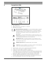
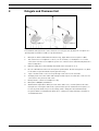
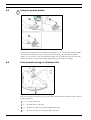
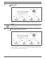
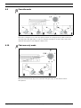
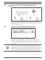
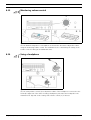
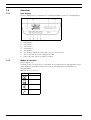
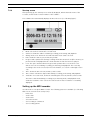
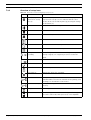
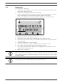
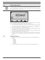
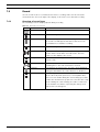
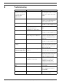
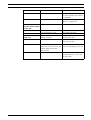
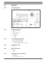
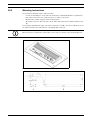
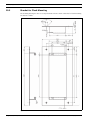
CCS 900 Ultro
Discussion System
en
Installation and Operating Manual
CCS 900 Ultro
Table of Contents | en
3
Table of Contents
1
About this manual
5
2
Introduction
6
3
Control Unit (CU)
7
4
Delegate and Chairman Unit
9
5
Installation
10
5.1
Connecting the Delegate and Chairman Units
10
5.2
Connecting up to 150 units
10
5.3
Locking the extension cable
11
5.4
Connecting an external microphone
11
5.5
Connecting a wireless microphone
12
5.6
Recording/playback the conversation
12
5.7
Connecting a PA-system or other external equipment
13
5.8
Connecting a telephone coupler
13
5.9
Connecting an equalizer
14
5.10
Mains connection
14
5.11
Connecting a USB cable
15
6
Operation
16
6.1
Testing the connection of the Delegate and Chairman Units
16
6.2
Using the microphone button of the Delegate Unit
16
6.3
Possible-To-Speak
17
6.4
Using the microphone button of the Chairman Unit
17
6.5
Using the priority button
18
6.6
Priority mode settings in Chairman Unit
18
6.7
Open mode
19
6.8
Open mode with auto switch-off
19
6.9
Override mode
20
6.10
Chairman only mode
20
6.11
Volume control of the Delegate and Chairman Units
21
6.12
Volume control of the Delegate and Chairman Units
21
6.13
Monitoring volume control
22
6.14
Using a headphone
22
7
Built-in MP3 recorder (CCS-CURD only)
23
7.1
Introduction
23
7.2
Overview
24
7.2.1
User display
24
7.2.2
Modes of operation
24
7.2.3
Start-up screen
25
7.3
Setting up the MP3 recorder
25
Bosch Security Systems B.V.
Installation and Operating Manual
IOM_CCS900 | V1.0 | 2010.06
4
en | Table of Contents
CCS 900 Ultro
7.3.1
Overview of set-up icons
26
7.3.2
Deleting files
27
7.3.3
Setting the date and time
28
7.3.4
Selecting the bit rate
28
7.3.5
Continuous recording
29
7.3.6
Set internal/ external recording options
29
7.4
Record
30
7.4.1
Overview of record icons
30
7.4.2
Making a recording
31
7.4.3
Exchanging SD cards during recording
31
7.5
Pre-listen and Playback
32
7.5.1
Overview of pre-listen/ playback icons
32
7.5.2
Pre-listening to and playing back files
33
8
Troubleshooting
34
9
Technical data
36
9.1
System Electrical and Electro-Acoustical Characteristics
36
9.1.1
The Control Unit (CU)
36
9.1.2
Combined Units
38
9.2
Mechanical Data
38
9.2.1
Control and Power Supply Unit
38
9.2.2
Delegate/Chairman Units
38
9.3
General data
39
9.3.1
System Environmental Conditions
39
9.3.2
Equipment Range
40
10
Appendix
41
10.1
Pin Configuration
41
10.1.1
Trunk Connections (A)
41
10.1.2
External Microphone (XLR) (B)
41
10.1.3
CINCH Connector (C)
41
10.1.4
Mains Connector (D)
41
10.1.5
Headphone Jack-plug (3.5mm) (E)
41
10.1.6
Schematics of connectors LBB 3316/00
42
10.2
Mounting Instructions
43
10.3
Bracket for Flush Mounting
44
IOM_CCS900 | V1.0 | 2010.06
Installation and Operating Manual
Bosch Security Systems B.V.
CCS 900 Ultro
1
About this manual | en
5
About this manual
This manual provides all the information required to install and operate the CCS 900 Ultro
Discussion System.
Conventions
WARNING!
Warnings draw attention to instructions that must be followed to prevent personal injury.
CAUTION!
Cautions draw attention to instructions that must be followed to prevent damage to the
equipment.
NOTICE!
Notes draw attention to special instruction tips or other useful information.
Bosch Security Systems B.V.
Installation and Operating Manual
IOM_CCS900 | V1.0 | 2010.06
6
2
en | Introduction
CCS 900 Ultro
Introduction
The CCS 900 Ultro Discussion System is a discussion system for use in meeting and
conference venues with a limited number of participants.
A CCS 900 Ultro Discussion System consists of:
–
One Control Unit (CU).
–
Maximum 50 units of which one or more Chairman Unit(s).
–
Extension cables if required (5m or 10m).
–
Peripheral audio and/or telecommunication equipment.
–
A built-in MP3 recorder.
The CU is the heart of the discussion system which controls the microphones of the Chairman
and Delegate Units as well as providing facilities for audio inputs and outputs. It also supplies
the power for the CU itself, Chairman Unit(s) and Delegate Unit(s).
With the use of Digital Acoustic Feedback Suppression the loudspeaker volume can be
increased significantly before feedback appears. A Digital Acoustic Feedback Suppressor is
only available in CCS-CUD / CCS-CURD.
A Delegate Unit enables participants to actively join in a discussion (i.e. speaking and
listening) by means of a microphone, controlled by an on/off button and a built-in loudspeaker
or external headphone.
A Chairman Unit has the same function as a Delegate Unit with the addition of a 'Priority'
button, that enables its operator to control the debate by temporary or permanently
overruling and muting all active microphones, depending on an internal setting in the
Chairman Unit.
The built-in MP3 recorder enables participants to: record discussions; listen to discussions
before playing it back to the floor; play discussions back to delegates.
IOM_CCS900 | V1.0 | 2010.06
Installation and Operating Manual
Bosch Security Systems B.V.
CCS 900 Ultro
3
Control Unit (CU) | en
7
Control Unit (CU)
Figure 3.1 Control Unit
1.
Mains On/Off switch.
2.
MP3 recorder (for more information, see section 7).
3.
Microphone-mode switch.
Open mode with auto switch-off. To select the maximum number of delegate
microphones to be activated simultaneously (1, 2, 3 or 4).The microphone
automatically switches off if the speaker does not speak for 30 seconds. The
microphone can manually be switched off by pushing the button on the
Delegate Unit.
Open mode. To select the maximum number of delegate microphones to be
activated simultaneously (1, 2, 3 or 4). The microphone must be switched on or
off manually by pushing the button on the Delegate Unit.
Override mode. Only one delegate microphone can be activated. If a new
delegate presses his microphone button, the microphone unit of the current
speaker will be switched off.
Chaiman only mode. Only the Chairman Units can be activated.
Test mode. For proper installation check. All the red LED’s and the light-rings
of the connected units will lit, if properly connected.
4.
Speaker volume control of all connected Delegate and Chairman Units.
5.
Volume control of the speaker or headphone of the CU.
6.
Headphone connection with 3.5 mm stereo jack plug socket.
7.
Trunk output 1 and 2. For loop through connection of the Delegate and Chairman Units.
To each output a maximum of 25 units can be connected. The maximum length of cable
between the outputs of the CU and the last unit in the system is 100 m (328 ft.).
8.
Microphone input with gain adjustment for external microphone. The external
microphone will be muted when the priority button on the Chairman Unit is pressed.
9.
Bosch Security Systems B.V.
Recorder input with gain control and recorder output connection.
Installation and Operating Manual
IOM_CCS900 | V1.0 | 2010.06
8
en | Control Unit (CU)
CCS 900 Ultro
10. Line input and output for connecting a PA-system or other audio equipment.
11. Telephone coupler input and output for connecting a remote participant.
NOTICE!
The telephone input signal to the CU is not added to the telephone output signal from the CU
to prevent line echo due to feedback.
12. Insertion connection. To connect an external audio equalizer for speech quality
improvement under difficult acoustic conditions (1 = without equalizer, 0 = insertion
connection is internally open, providing means to connect an external equalizer in the
path from microphone signals to delegate/chairman loudspeakers).
NOTICE!
Position "1" required for internal loop-through of the microphone signals to the Delegate /
Chairman Unit loudspeakers.
13. Digital Acoustic Feedback Suppressor (DAFS) switch to activate or deactivate the DAFS
(optional).
14. USB connector. Used for downloading recorded speech to a PC (optional).
15. Mains input connection. Use the included mains cord to connect the CU to the mains
socket. In some countries it may be necessary to replace the supplied mains cable by a
local one. Brown = live, blue = neutral and green/yellow = earth. (Replacement and color
indication not applicable to mains cords for North America).
IOM_CCS900 | V1.0 | 2010.06
Installation and Operating Manual
Bosch Security Systems B.V.
CCS 900 Ultro
4
Delegate and Chairman Unit | en
9
Delegate and Chairman Unit
Figure 4.1
The Chairman Unit (B) has the same function as a Delegate Unit (A) with the exception of a
'priority' button and the Possible-To-Speak indication.
1.
2.
Microphone with red illuminated indicator ring, lights when the microphone is ON.
Two 3.5 mm stereo headphone sockets, one at each side, for headphone or recorder
connection. Insertion of a headphone jack in one or both sockets automatically mutes the
unit's loudspeaker.
3.
Built-in loudspeaker, automatically muted when the microphone is on.
4.
Bi-color LED indicator above the microphone push button. Red for microphone on, white
for Possible-To-Speak indication (Delegate Unit only).
5.
6.
7-pole circular female socket for loop through connection to the next unit.
2m flying lead connection cable with sturdy moulded 7-pole circular male connector for
connection to the previous unit or CU.
7.
Rotary volume control for headphones only.
8.
Microphone ON/OFF push-button.
9.
Chairman Priority button. When pressed emits chime tone, overrules/mutes all active
microphones of Delegate Units in the system and keeps the chairman's microphone on
for as long as the button is pressed (setting can be changed in the Chairman Unit).
In systems with several Chairman Units these settings are independently selectable for
each Chairman Unit.
Bosch Security Systems B.V.
Installation and Operating Manual
IOM_CCS900 | V1.0 | 2010.06
10
en | Installation
CCS 900 Ultro
5
Installation
5.1
Connecting the Delegate and Chairman Units
Figure 5.1
Connect the Delegate (2) and Chairman (3) Units to the trunk connectors of the CU (1). Use
an extension cable (4) if necessary.
5.2
Connecting up to 150 units
The CCS 900 Ultro can be used with up to 150 units by adding a maximum of 2 additional
Control Units acting as power supply units only. Please contact your local Bosch
representative for the installation instructions.
Figure 5.2 Connecting 6 x 25 units
IOM_CCS900 | V1.0 | 2010.06
Installation and Operating Manual
Bosch Security Systems B.V.
CCS 900 Ultro
5.3
Installation | en
11
Locking the extension cable
Figure 5.3
Cable locking clamps can be used in combination with the extension cables to prevent
accidental disconnection.
5.4
Connecting an external microphone
Figure 5.4
Put the external microphone (2) connector in the microphone input of the CU (1). Adjust the
sensitivity by use of the gain control (3). Use only microphones with balanced output. The
microphone input provides a 12V phantom power supply.
Bosch Security Systems B.V.
Installation and Operating Manual
IOM_CCS900 | V1.0 | 2010.06
12
5.5
en | Installation
CCS 900 Ultro
Connecting a wireless microphone
Figure 5.5
Connecting a wireless microphone to the external microphone input is possible with the
included 50dB attenuator. This way of connection allows interruption of the wireless
microphone by the chairman's priority button.
5.6
Recording/playback the conversation
Figure 5.6
Connect the cabling of the recorder device (2) to the recorder input and output of the CU (1).
Use the gain control (3) to adjust the sensitivity of the recorder input of the CU.
IOM_CCS900 | V1.0 | 2010.06
Installation and Operating Manual
Bosch Security Systems B.V.
CCS 900 Ultro
5.7
Installation | en
13
Connecting a PA-system or other external equipment
Figure 5.7
Connect a PA-system (3) or other devices (2) to the in- and output of the CU (1). Connect
audio sources to the line input, a PA amplifier or other sound-processing devices to the line
output.
5.8
Connecting a telephone coupler
Figure 5.8
Connect the telephone coupler (2) to the telephone input and output of the CU (1). The
telephone coupler is further connected to the telephone wall socket (4) and a telephone (3)
for dialing.
A connection to a telephone network must always be made via a telephone coupler that
provides adequate isolation between the telephone network (PBX) and the CCS 900 Ultro
system. The telephone coupler shall also meet all relevant requirements for this type of
communication equipment as imposed by law and/or responsible telecommunication
organizations in the country of use.
CAUTION!
Never try to make a direct connection between the telephone network and the CCS 900 Ultro
discussion system.
Bosch Security Systems B.V.
Installation and Operating Manual
IOM_CCS900 | V1.0 | 2010.06
14
en | Installation
5.9
CCS 900 Ultro
Connecting an equalizer
Figure 5.9
Put the insertion switch (3) in position "0" and connect the cabling (2) of the (mono)
equalizer (4) to the insertion input and output of the CU (1). Switch (3) must be in position
"1" (loop through) if the insertion input/output is not used.
5.10
Mains connection
Figure 5.10
WARNING!
The CU must be earthed via the mains supply for safety reasons and to ensure the specified
audio performance of the system. Do not open the CU and/or Delegate/Chairman Units, no
user serviceable parts inside.
Use the supplied mains cord set (5) to connect the CU (1) to a protective earthed mains
socket (2). Press the on/off switch (3) to power up the system, the display (4) will be lit
(CCS-CURD only).
IOM_CCS900 | V1.0 | 2010.06
Installation and Operating Manual
Bosch Security Systems B.V.
CCS 900 Ultro
5.11
Installation | en
15
Connecting a USB cable
Use the optional USB cable to connect the CU (1) to a PC. Data can then be downloaded from
the CU to the PC (CCS-CURD only). See section 7 for more information.
CAUTION!
Do not connect the USB cable and audio output/input to the same PC, otherwise the system
will not work.
CAUTION!
Do not disconnect the USB cable or shut down the Control Unit without following the PC
disconnection procedures.
Bosch Security Systems B.V.
Installation and Operating Manual
IOM_CCS900 | V1.0 | 2010.06
16
en | Operation
CCS 900 Ultro
6
Operation
6.1
Testing the connection of the Delegate and Chairman Units
Figure 6.1
Put the mode selector in the test position, all light-ring indicators and red LEDs of the
Delegate and Chairman Units must lit if properly connected.
6.2
Using the microphone button of the Delegate Unit
Figure 6.2
Depending on the position of the microphone mode switch on the CU, pressing the
microphone button on a Delegate Unit will activate the delegate microphone. Pressing again
switches the microphone off.
IOM_CCS900 | V1.0 | 2010.06
Installation and Operating Manual
Bosch Security Systems B.V.
CCS 900 Ultro
6.3
Operation | en
17
Possible-To-Speak
Figure 6.3
LED (A) in figure 6.3 shows Possible-To-Speak. When the LED has the white color this
indicates the microphone can be switched on. When the microphone is switched on the color
of the LED will change to red. If the maximum number of active microphones in the system is
reached the LED will be off and the microphone can not be switched on.
The Possible-To-Speak indication can be disabled.
0 : indication disabled.
1 : indication enabled (default).
6.4
Using the microphone button of the Chairman Unit
Figure 6.4
Pressing the microphone button on a Chairman Unit always activates the chairman
microphone, independent of the selected microphone mode. Chairman Units don't switch off
automatically.
Bosch Security Systems B.V.
Installation and Operating Manual
IOM_CCS900 | V1.0 | 2010.06
18
6.5
en | Operation
CCS 900 Ultro
Using the priority button
Figure 6.5
Pressing the priority button of the Chairman Unit (Figure 6.5 “1”) may be indicated by a chime
tone and will deactivate all active Delegate Units and activates the chairman microphone
(Figure 6.5 “2”). Release of the priority button (Figure 6.5 “3”) will either leave the Delegate
Units deactivated or activates them again (depending on priority mode settings).
6.6
Priority mode settings in Chairman Unit
Figure 6.6
Remove the cable relief bracket (1) to set the chime and microphone switches in the required
position at priority.
0 = : no chime at priority
1 = : (default) chime at priority
0 = : delegate microphones permanently OFF at priority
1 = : (default) microphones temporary OFF at priority
IOM_CCS900 | V1.0 | 2010.06
Installation and Operating Manual
Bosch Security Systems B.V.
CCS 900 Ultro
6.7
Operation | en
19
Open mode
Figure 6.7
Select the max. number (1, 2, 3 or 4) of delegate microphones which can be active at the
same time.
NOTICE!
Chairmen can always switch on and off their microphones and are not included in the
maximum number.
6.8
Open mode with auto switch-off
Figure 6.8
Select the max. number (1, 2, 3 or 4) of delegate microphones which can be activated by the
delegates themselves at the same time. If the speaker is silent for approximately 30 seconds
the active microphone switches off automatically.
Bosch Security Systems B.V.
Installation and Operating Manual
IOM_CCS900 | V1.0 | 2010.06
20
en | Operation
6.9
CCS 900 Ultro
Override mode
Figure 6.9
Each time a delegate presses the microphone button on a Delegate Unit, it will override the
currently active Delegate Unit. So only one delegate microphone is active at the same time.
chairman microphones can always be switched on.
6.10
Chairman only mode
Figure 6.10
Only the Chairman Units (B) can be activated. Delegates (A) can not switch on their
microphones.
IOM_CCS900 | V1.0 | 2010.06
Installation and Operating Manual
Bosch Security Systems B.V.
CCS 900 Ultro
6.11
Operation | en
21
Volume control of the Delegate and Chairman Units
Figure 6.11
Turn the volume control (1) to set the volume of the loudspeakers of the Delegate and
Chairman Units (2). Adjust for maximum level without feedback. In the fully counterclockwise
position all loudspeakers are muted.
6.12
Volume control of the Delegate and Chairman Units
Figure 6.12
Put the Digital Acoustic Feedback Suppressor switch (1) in position "0" and adjust the
loudspeakers for maximum level without feedback. Switch Digital Acoustic Feedback
Suppression on by changing the switch (1) to position "1". Then set the loudspeaker volume
to the required level, but increasing the volume level more than 2 or 3 steps is not
recommended.
NOTICE!
With the use of Digital Acoustic Feedback Suppression the loudspeaker volume can be
increased significantly before acoustic feedback appears. The maximum achievable volume
gain depends on the acoustical environment and positioning of the units. Artefacts may occur
during microphone switching at very high volume levels. In general the achievable increased
volume gain is 4 - 6 dB. The Digital Acoustic Feedback Suppression is optimized for speech.
Bosch Security Systems B.V.
Installation and Operating Manual
IOM_CCS900 | V1.0 | 2010.06
22
en | Operation
6.13
CCS 900 Ultro
Monitoring volume control
Figure 6.13
Use the built-in loudspeaker or a headphone to monitor the discussion. Adjust the volume
using the monitoring volume control. The maximum level is controlled by the setting of the
volume control for Delegate and Chairman Units.
6.14
Using a headphone
Figure 6.14
Use the rotary volume control (1) to adjust the volume of the headphones connected to the
left and/or right side of the units. Inserting a headphone jack mutes the loudspeaker. The
maximum level depends on the setting of the volume control (2) on the CU.
IOM_CCS900 | V1.0 | 2010.06
Installation and Operating Manual
Bosch Security Systems B.V.
CCS 900 Ultro
Built-in MP3 recorder (CCS-CURD only) | en
7
Built-in MP3 recorder (CCS-CURD only)
7.1
Introduction
23
NOTICE!
Connect the Control Unit at least ones every 6 months to the mains supply for 24 hours to
keep the MP3 back-up battery charged.
The built-in MP3 recorder allows users to:
–
record discussion
–
listen to discussion before playing it back to the floor
–
play discussion back to delegates
Recording is started and stopped by the user. The settings of the MP3 recorder can be
changed so that recording only takes place when any one of the microphones is active (for
more information, see section 7.3). The MP3 recorder will record the audio from external
devices if connected.
When recording is activated, the MP3 recorder will automatically create an MP3 file, using the
current date and time as the file name. Recorded files have a maximum duration of 60
minutes. After 60 minutes, the file will be automatically closed, and a new file will be created.
This process is repeated as long as recording is active or until the SD card is full.
Recorded speech is saved on an SD card, which is inserted into the top of the unit (see
following figure), or saved internally. After recording, the SD card can be removed, or the
recorded speech can be downloaded to a PC by connecting a USB cable to the back of the
CCS Control Unit.
The MP3 recorder has a card exchange feature that allows the user to exchange the SD card
during conversation without loss of discussion/audio (for a full explanation of this feature, see
section 7.4.3).
Once discussion has been recorded, the user can choose to pre-listen to or playback the file
(for more information, see section 7.5).
Bosch Security Systems B.V.
Installation and Operating Manual
IOM_CCS900 | V1.0 | 2010.06
24
en | Built-in MP3 recorder (CCS-CURD only)
7.2
Overview
7.2.1
User display
CCS 900 Ultro
The user display has five soft buttons for operating the MP3 recorder (see following figure).
Figure 7.1 Overview of user display and buttons
7.2.2
1.
Soft button 1
2.
Soft button 2
3.
Soft button 3
4.
Soft button 4
5.
Soft Button 5
6.
User display: displays user data and icons (see section 7.2.3).
7.
Slot for SD card: Slot for inserting the SD card.
8.
LED for SD card: LED is on during recording.
Modes of operation
Refer to Figure 7.1
Use button (1) to select the mode of operation. An icon appears in the top right-hand corner
of the display to show which mode is selected. The following modes are available (see
following table).
Table 7.1
Icon
Mode selected icons
Mode selected
Record
Pre-listen
Playback
Set-up
IOM_CCS900 | V1.0 | 2010.06
Installation and Operating Manual
Bosch Security Systems B.V.
CCS 900 Ultro
7.2.3
Built-in MP3 recorder (CCS-CURD only) | en
25
Start-up screen
After powering up, the start-up screen is briefly displayed, which shows the name of the
recorder, as well as the revision number of the software.
The software then automatically displays the Record screen (see following figure).
Figure 7.2 Overview of record screen (after start-up)
1.
Mode selected icon: Shows the selected mode
2.
VU-meter: Shows the audio level during recording, pre-listening, and playback.
3.
Change mode icon: Shows the user when another mode can be selected.
4.
Date: Shows the date in year, month, day format.
5.
Progress and separator line: during recording shows the amount of used/free memory. In
pre-listen mode and playback mode shows how much of the file has been played.
6.
Icons: The space underneath the Progress and separator line is reserved for icons.
Various icons are used during recording, pre-listening, and playback. The icons vary
according to the mode selected (for more information, see section 7.3 through section
7.5).
7.
Time: Shows the time in hours, minutes, and seconds.
8.
Time counter: Shows the elapsed time during recording, pre-listening, and playback.
9.
Total time: In record mode, shows the remaining time in hours, minutes, and seconds.
The timer counts down during recording; in pre-listening mode, and playback mode,
shows the total time of the selected recorded session. Note: Total time is constantly
displayed.
7.3
Setting up the MP3 recorder
Use this mode to set-up the MP3 recorder. The following options are available (see following
table for an overview of the set-up icons):
–
Delete files
–
Set the date
–
Set the time
–
Select the bit rate
–
Set recording to continuous
–
Set recording options
Bosch Security Systems B.V.
Installation and Operating Manual
IOM_CCS900 | V1.0 | 2010.06
26
en | Built-in MP3 recorder (CCS-CURD only)
7.3.1
CCS 900 Ultro
Overview of set-up icons
Table 7.2
Icon
Overview of icons for navigating set-up screens
Icon name
Function of icon
Next (displayed at
Go to next set-up screen. This icon is also displayed at the
lower left of set-up
top left of the set-up screen to indicate that the other
screen)
modes can be selected at any time, by pressing the change
mode button (1).
Select
Selects next value to change.
Down
Decreases value, or selects another value or file.
Up
Increases value, or selects another value or file.
Date
Indicates that the date set-up screen is selected.
Time
Indicates that the time set-up screen is selected.
Bit rate
Indicates that the bit rate set-up screen is selected.
Microphone
Unit will only record if one or more delegate microphones
recording
pick-up a signal, or if a signal is present on a external
input.
Continuous recording Unit will continuous record.
Confirm delete
Confirms file to be deleted.
Delete file
Permanently deletes selected file.
Cancel delete
Cancels the delete file command.
Record to card
Sets up recording so that files are saved to the SD card.
Data will still be saved to the internal memory during card
exchange, as described in section 7.4.3.
Record to memory
Sets up recording so that files are saved to the internal
memory.
Hourglass
Initializing SD card.
SD card status
Card flashing at 2 Hz: card is initializing.Card flashing at 5
Hz: card is either: full, write protected, or incompatible.
IOM_CCS900 | V1.0 | 2010.06
Installation and Operating Manual
Bosch Security Systems B.V.
CCS 900 Ultro
7.3.2
Built-in MP3 recorder (CCS-CURD only) | en
27
Deleting files
Use this option to delete files.
1.
Press the up or down button to select the file to delete. The filename will change on the
display as the button is pressed.
2.
3.
Press the delete file button to delete the selected file.
Press the confirm delete button to confirm the file to delete permanently or cancel the
delete command of the selected file by pressing the button “cancel delete”.
4.
Press the select button to select the next value to change (see following section).
Figure 7.3 Delete screen
1.
Mode selected icon: Set-up mode is selected.
2.
Change mode icon: Shows the user when another mode can be selected.
3.
File name: Shows the name of the selected audio file (default name is the date and time
of the recording).
4.
Set-up item: Shows the selected set-up item.
5.
File counter: Shows the selected file number and the total number of files.
6.
Time counter: Shows the elapsed time of all recordings on disk.
7.
Space usage and separator line: Shows the used capacity of all files and the free space
on the SD card or internal memory.
8.
Button icons: See table 7.2.
NOTICE!
With refer to the file counter in figure 7.3. If the total number of files exceeds 99 then the last
digit or two digits might not be displayed.Example: if file 86 from all 120 files is selected it will
be shown as 86-12.
NOTICE!
After deleting a file, the software jumps back to the delete file screen.
Bosch Security Systems B.V.
Installation and Operating Manual
IOM_CCS900 | V1.0 | 2010.06
28
en | Built-in MP3 recorder (CCS-CURD only)
7.3.3
CCS 900 Ultro
Setting the date and time
NOTICE!
To change settings in the set-up mode, you must follow the programmed sequence of events
(there is no back button). To exit the set-up mode at any time, press the change mode button
(button 1 at the left-side of the display).
Figure 7.4 Set-up screen for date
Before using the MP3 recorder you should make sure that the date and time are correctly set.
If necessary, adjust the date and time as follows:Refer to Figure 7.1
1.
Press the change mode button (1) to select the set-up mode. When selected, the set-up
icon should be shown in the top right-hand corner of the display (see following figure).
2.
3.
Press the select button (2) to change the date settings.
Press the up or down button (4 or 5) to change the value (year number), and then press
the next button (3) to select the next value to change.
4.
Set the date (year, month, and day) as described in the previous step, and then press the
select button (2) to jump to the time set-up screen.
5.
Set the time (hours, minutes, and seconds), using the same method as described in step
3, and then press the select button to jump to the bit rate set-up screen (see following
section).
7.3.4
Selecting the bit rate
1.
Press the up or down button to change the value (bit rate). The following bit rates are
available:
2.
IOM_CCS900 | V1.0 | 2010.06
–
64 kbps
–
96 kbps
–
128 kbps
–
192 kbps
–
256 kbps
Press the select button to select the next value to change (see following section).
Installation and Operating Manual
Bosch Security Systems B.V.
CCS 900 Ultro
7.3.5
Built-in MP3 recorder (CCS-CURD only) | en
29
Continuous recording
NOTICE!
If more than 50 Delegate Units are connected (by using additional Control Units), the option
“record when one or more microphones are active” may not work correctly (also see section
5.2).
Also the noise level of external inputs can have impact on the proper functioning of the option
“record when one or more microphones are active”.
1.
Press the down button to switch between constant recording or record when one or
more microphones are active (see table 7.2).
2.
7.3.6
Press the select button to select the next value to change (see following section).
Set internal/ external recording options
Refer to figure 7.1
1.
Press the down button to switch between record to the SD card or record to the internal
memory (refer to table 7.2).
2.
Bosch Security Systems B.V.
Press the change mode button (1) to exit the set-up mode.
Installation and Operating Manual
IOM_CCS900 | V1.0 | 2010.06
30
en | Built-in MP3 recorder (CCS-CURD only)
7.4
CCS 900 Ultro
Record
Use the record mode to record discussion. Before recording, make sure the SD card is
inserted into the slot to the right of the display, or the unit is set to internal recording.
7.4.1
Overview of record icons
The following icons are displayed/used during recording.
Table 7.3
Icon
Overview of record icons
Icon name
Function of icon
Record selected
Shows the user that the Record mode is selected.
Record
Starts recording session.
Pause
Pauses recording session. When recording has been paused,
the record icon will appear and start to flash. Press the
record button to reactivate recording.
Stop
Stops recording session
New file
Creates a new file during recording (recording continues,
but the data is saved under a new file name. The time
counter on the display is also reset).
Change card
Allows the user to change the SD card during recording (see
section 7.4.3).
Change card timer
Graphically shows the user how many seconds are
remaining before the new card must be inserted.
Hourglass
Icon will flash at 2Hz when the SD card is being initialized.
During the initialization all control buttons are disabled.
SD card status
Card flashing at 2 Hz: card is missing.Card flashing at 5 Hz:
card is either full, write protected, or incompatible.Note:
This icon is not shown during the card exchange procedure
or when the internal memory option is selected in the set-up
mode.If during the card exchange procedure a card is not
inserted within one minute of pressing the change card
button, this icon will appear.
IOM_CCS900 | V1.0 | 2010.06
Installation and Operating Manual
Bosch Security Systems B.V.
CCS 900 Ultro
7.4.2
Built-in MP3 recorder (CCS-CURD only) | en
31
Making a recording
Refer to figure 7.1.
Make a recording as follows:
1.
Press the change mode button to select the record mode. When selected, the record icon
is shown in the top right-hand corner of the display.
NOTICE!
If the unit has just been powered up, the record mode is automatically selected.
2.
Press the record button (2) to start recording. The blue LED next to the SD card holder
will come on and the time counter will start.
3.
During recording you can:
–
press the pause button (2) to temporarily halt recording.
–
press the stop button (3) to stop recording and close the recording session.
–
press the new file button (4) to create a new file.
–
change the SD card by pressing the change card button (5) on the display (see
section 7.4.3).
NOTICE!
The record feature supports a maximum of 999 recorded files.
7.4.3
Exchanging SD cards during recording
The SD card can be changed at any time during recording, but the new card must be inserted
within one minute of pressing the change card button (5). This allows discussion to continue
even when the SD card is full. If the new card is not inserted within 1 minute, the card missing
icon will be shown and recording will stop. The last minute of recorded discussion will also be
lost.
When there is 5 minutes of recording time left on the card, three short beeps will be played
through the monitor loudspeaker. This is to warn the operator to change the card. If the card
is not changed within 5 minutes, a long beep will be played through the monitor loudspeaker
at 0 minutes, and the card exchange function will automatically start.
NOTICE!
If a headphone is connected to the Control Unit, the beeps can only be heard via the
headphone, and the blue LED will flash quickly (5Hz).
Refer to figure 7.1.
Change the card as follows:
1.
Remove the current card.
–
When the card is removed, the recorder will continue recording to the internal buffer
of the recorder.
2.
Insert the new card within one minute of pressing the change card button (5).
–
When the new card is inserted, a new file is automatically started using the current
date and time as the file name. This file includes the previous 90 seconds of
discussion (60 seconds from the internal buffer and the last 30 seconds of
discussion from the previous card). This feature also allows transcription to take
place off-line before the meeting has ended.
Bosch Security Systems B.V.
Installation and Operating Manual
IOM_CCS900 | V1.0 | 2010.06
32
en | Built-in MP3 recorder (CCS-CURD only)
7.5
CCS 900 Ultro
Pre-listen and Playback
Refer to figure 7.1.
Pre-listen and Playback are almost the same. The difference between these two modes is
described below:
Pre-listen
Use the pre-listen mode to listen to discussion before playing it back to the floor. The audio
signal is present at the monitor loudspeaker or the headphones, if connected.
Playback
Use the playback mode to play the discussion back to delegates. The audio signal is present at
the monitor loudspeaker or the headphones, if connected, as well as at the delegate
loudspeakers.
7.5.1
Overview of pre-listen/ playback icons
The following icons are displayed/used during pre-listening and playback.
Table 7.4
Icon
Overview of pre-listen and playback icons
Icon name
Function of icon
Pre-listen
When pre-listen is selected, this icon is shown at the top right-hand
corner of the display.
Playback
When playback is selected, this icon is shown at the top right-hand
corner of the display.
Start
Starts the pre-listen or playback session depending on mode
selected. The first file in the list will be played. As soon as this file
has been played, the next valid file will start.
Pause
Pauses the pre-listen or playback session, depending on the mode
selected. When pre-listen or playback has been paused, the start
icon will appear and start to flash. Press the start button to continue
with the session.
Stop
Stops the pre-listen or playback session depending on the mode
selected.
Previous
Skips to previous file (also see fast rewind).Icon is only shown if a
valid file is available. Note: Jumps to the last file in the list once the
beginning of the list has been reached.
Next
Skips to next file (also see fast forward). Icon is only shown if a valid
file is available. Note: Jumps to the first file in the list once the end
of the list has been reached.
Fast rewind Fast rewinds to the beginning of the file (10x normal speed). Icon
will only appear if the previous button is pressed and held in for 2
seconds or longer.
Fast
Fast forwards to the end of the file (10x normal speed). Icon will
forward
only appear if the next button is pressed and held in for 2 seconds or
longer.
IOM_CCS900 | V1.0 | 2010.06
Installation and Operating Manual
Bosch Security Systems B.V.
CCS 900 Ultro
7.5.2
Built-in MP3 recorder (CCS-CURD only) | en
33
Pre-listening to and playing back files
Refer to figure 7.1
To pre-listen to or playback files:
1.
Press the change mode button (1) to select the required mode. The pre-listen or
playback icon is shown in the top right-hand corner of the display, depending on the
mode selected.
2.
Press the start button (2) to pre-listen to or playback files. The MP3 tag is shown on the
display. If there is no MP3 tag, the filename is shown instead.
3.
Bosch Security Systems B.V.
During pre-listening or playback you can:
–
switch between pre-listen and playback, by pressing the change mode button (1).
–
press the pause button to temporarily halt playback.
–
press the stop button to stop pre-listening or playback.
–
skip to the previous track (press and hold to fast rewind).
–
skip to the next track (press and hold to fast forward).
Installation and Operating Manual
IOM_CCS900 | V1.0 | 2010.06
34
8
en | Troubleshooting
CCS 900 Ultro
Troubleshooting
Problem
Possible cause
Solution
Temporary no
Trunk-line overload.
Reduce load on the trunk-lines
microphone reaction, and
by reducing the number of units,
no sound or distorted
and/or the length of the trunk
sound from unit
cables.
loudspeakers.
Acoustic Feedback:
Loudspeaker volume too loud.
Reduce gain using volume
control for Delegate/Chairman
Unit loudspeakers on CU.
If available, switch on Digital
Acoustic Feedback Suppression.
Distance between units too
Increase distance between
small (microphone to
units.
loudspeaker of other units).
If available, switch on Digital
Acoustic Feedback Suppression.
Too close to microphone units,
Increase the distance between
when using open headphones.
headphone and microphone or
disconnect headphones when
not in use.
If available, switch on Digital
Acoustic Feedback Suppression.
Part of system not
Interrupted trunk-line cabling.
working.
Check the trunk-line cabling
connections between the units
and the CU, also use the test
function on the CU.
No sound via delegate /
Insertion switch in wrong
Check if insertion switch at the
chairman loudspeakers:
position.
rear of the CU is in position "1".
Volume control position.
Check if the volume control for
delegate/chairman loudspeakers
on the CU is not in the fully
counter clockwise position.
Microphone active or
Notice: units with active
headphone connected.
microphone or connected
headphone(s) have their
loudspeakers switched off.
Hourglass flashes very
The SD card is full.
fast:
Check SD card, and remove files
if necessary.
Use a PC to format the card. Use
FAT or FAT32. Note: NTFS is
incompatible.
The SD card is write protected.
Remove SD card, and disable
the write protection.
IOM_CCS900 | V1.0 | 2010.06
Installation and Operating Manual
Bosch Security Systems B.V.
CCS 900 Ultro
Troubleshooting | en
Problem
Possible cause
The SD card is incompatible.
35
Solution
Use a PC to format the SD card.
Use FAT or FAT32. Note: NTFS is
incompatible.
Notice: SD cards larger than 2
GB are not supported.
Hourglass flashes for a
The SD card is almost full.
Remove old files/recordings.
long time after inserting
the SD card:
Format the SD card.
The SD card is too slow.
Use a faster SD card.
Recorded files missing
The SD card was removed
Always stop recording before
on SD card:
during recording.
removing SD card.
Select SD card exchange before
removing SD card.
User display is blank:
During CU power up, the USB
Make sure the USB cable is not
cable was connected to the CU
connected during CU power up.
and PC, while the PC was
switched off.
Make sure the PC is fully
operational before connecting
the USB cable.
Bosch Security Systems B.V.
Installation and Operating Manual
IOM_CCS900 | V1.0 | 2010.06
36
en | Technical data
CCS 900 Ultro
9
Technical data
9.1
System Electrical and Electro-Acoustical Characteristics
9.1.1
The Control Unit (CU)
Mains voltage
100 - 240 Vac ± 10%, 50/60 Hz
Current consumption
max. 0.9 A (100 Vac) - 0.3 A (240 Vac)
Power Consumption
60 W
DC supply to contribution units 24V +/- 1V (current limited)
Rated output for all trunks
1.25A
Sample frequency:
- Recording
32Khz
- Playback
32, 44.1 and 48Khz
Bite rate:
- Recording
64, 96, 128, 192, 256 Kbit/sec
- Playback
any bit rate
Media:
- MP3-tag
Compatible conform ID3V2
- Memory card
Any SD card up to 2 GB compatible (high speed cards are
advised).
Line, telephone coupler and
insertion in/outputs
(unbalanced):
- Input sensitivity
-14 dBV / +11dBV (nominal/maximum)
- Input impedance
33 kOhm
- Output level
-14 dBV / +11dBV (nominal/maximum)
- Output impedance
500 Ohm
Recorder in/output
(unbalanced) - mono:
- Input sensitivity
- 20 dBV / + 5 dBV (nominal/maximum)
- Input sensitivity adjustment
+0 / -20 dB
- Input impedance
47 kOhm (for L and R channel)
- Output level
- 20 dBV/ + 5 dBV (nominal/maximum)
- Output impedance
500 Ohm
External microphone input
(balanced):
- Input sensitivity
- 56 dBV (- 6 dBV via included adapter)
- Input sensitivity adjustment
+6 dB / -6 dB
- Phantom supply
12V +/- 1V, 2 x 680 W (+/- 2%). (Phantom supply is not
available when using the included adapter)
Monitor loudspeaker:
- Output level at 0.5 m
72 dB SPL/ 82 dB SPL (nominal/maximum)
- Frequency response
320 Hz ... 10 kHz (-10 dB, ref. 1kHz)
- Impedance
25 ohm
IOM_CCS900 | V1.0 | 2010.06
Installation and Operating Manual
Bosch Security Systems B.V.
CCS 900 Ultro
Technical data | en
- Volume control
37
50 dB attenuation range
Monitor headphone:
- Output level
-8 dBV/ +2 dBV (nominal/maximum)
- Output impedance
22 Ohm
- Output connection
stereo jack socket (mono output)
- Allowed impedance
any impedance
- Volume control
50 dB attenuation range
Loudspeaker volume control:
- For Delegate and Chairman
mute (50 dB attenuation) + 10 steps of 1.9 dB
Units
Limiter threshold level:
- To unit loudspeaker /
10 dB above nominal level
headphone
Gain reduction due to NOM:
- Number of Open Microphones NOM +/- 1 dB
Auto microphone switch-off
After approximately 30 sec. not speaking (sound level
function selectable on the
below 64 dB SPL) the microphone is automatically
Control and Power Supply Unit switched off
System limits:
Number of Delegate / Chairman Units connected to CU
- Maximum in total
50
- Maximum per trunk output
25
- Maximum trunk length using
100 m (328 ft.)
CCS 900 Ultro standard cabling
Table 9.1 Recording capacity
Recording capacity
Card size
Internal
memory
Bit rate
512 MB
1 GB
2 GB
225 MB
64
17h:14m
34h:28m
64h:56m
7h:34m
96
11h:29m
22h:59m
45h:58m
5h:02m
128
8h:37m
17h:14m
34h:28m
3h:47m
192
5h:44m
11h:29m
22h:58m
2h:31m
256
4h:18m
8h:37m
17h:14m
1h:53m
The times mentioned in the table might slightly differ depending on the SD card.
Bosch Security Systems B.V.
Installation and Operating Manual
IOM_CCS900 | V1.0 | 2010.06
38
en | Technical data
9.1.2
CCS 900 Ultro
Combined Units
Delegate microphones with transmission links to delegate headphones and auxiliary outputs.
Frequency response
25 Hz - 12.5 kHz tolerances according to IEC 60914
standard
Total harmonic distortion at
overload:
- at nominal input level (85 dB
< 0.5%
SPL)
- at max. input level (110 dB
< 3%
SPL)
9.2
Mechanical Data
9.2.1
Control and Power Supply Unit
Mounting
free standing on a table top or mounted in a 19" rack
(requires 3HU (Height Units) with bracket set LBB 3311/
00). Information about how to make the necessary brackets
for table flush mounting is included.
Dimensions (HxWxD)
84 x 361 x 143 mm (with 5.5 mm feet)3.4 x 14.2 x 5.6 in
(with 0.22 in feet).
Weight
CCS-CU version 1.6 kg (3.5 lb.)CCS-CUD version 1.7 kg (3.7
lb.)CCS-CURD version 1.8 kg (4.0 lb.)
9.2.2
Delegate/Chairman Units
Dimensions (H x W x D) without 71 x 220 x 140 mm (2.80 x 8.66 x 5.51 in)
mic.
Height with mic. in horizontal
132 mm (5.20 in)
position
Length of mic. from mounting
CCS-DS and CCS-CMS version, 313 mm (12.3 in)CCS-DL
surface
and CCS-CML version, 488 mm (19.2 in)
Weight
Approx. 1 kg (2.2 lb.)
Color (top and base)
Charcoal (PH 10736)
IOM_CCS900 | V1.0 | 2010.06
Installation and Operating Manual
Bosch Security Systems B.V.
CCS 900 Ultro
Technical data | en
9.3
General data
9.3.1
System Environmental Conditions
39
Temperature range:
- Storage and transport
-20 to +70°C (-4 to +158°F)
- Operational
+5 to +45°C (+41 to 113°F)
Ambient humidity:
- Operational
20% - 95% RH
- Storage and transport
0% - 99% RH
Air pressure
600 mBar - 1100 mBar
Safety
according to EN 60065 and according to UL 60065
Resistance to shock, vibration, according to IEC 60068, 5G acceleration
bump and transport
EMC emission
according to EN 55103-1 and FCC rules (part 15), class A
EMC immunity
according to EN 55103-2
EMC approvals
affixed with the CE mark
Mains harmonics
EN 61000-3-2 and EN61000-3-3
Transport
AV18-Q0681
Bosch Security Systems B.V.
Installation and Operating Manual
IOM_CCS900 | V1.0 | 2010.06
40
en | Technical data
9.3.2
CCS 900 Ultro
Equipment Range
Control and power supply unit CCS-CU
CCS-CUD (with Digital Acoustic Feedback Suppression)
CCS-CURD (with recording and Digital Acoustic Feedback
Suppression)
19" rack mounting set
LBB 3311/00
Bracket for flush mounting
Can be made locally according to the illustrations in
chapter 10.2
Delegate Unit(s)
CCS-DS (short microphone)
CCS-DL (long microphone)
Chairman Unit(s)
CCS-CMS (short microphone)CCS-CML (long microphone)
Installation cable with
LBB 3316/00 (100 m)
connectors
Extension cables
LBB 3316/05 (5m)
LBB 3316/10 (10m)
Cable locking clamps
LBB 4117/00 (set of 25 pieces)
Cable clamp
DCN-DISCLM (set of 25 pieces)
Transport suitcase for 10
CCS-SC10
Delegate/Chairman Units with
standard microphone
Transport suitcase for one CU, CCS-SC6
6 Delegate/Chairman Units
with standard (short)
microphone and some
extension cables
IOM_CCS900 | V1.0 | 2010.06
Installation and Operating Manual
Bosch Security Systems B.V.
CCS 900 Ultro
Appendix | en
10
Appendix
10.1
Pin Configuration
Figure 10.1
10.1.1
10.1.2
1.
Audio contribution line
2.
GND
3.
Audio distribution line
4.
Control line 1
5.
Control line 2
6.
V+ supply
7.
V- supply
External Microphone (XLR) (B)
GND (0V, phantom supply)
2.
Signal+ (+12V, phantom supply)
3.
Signal- (-12V, phantom supply)
–
10.1.4
Phantom supply according to DIN45596
CINCH Connector (C)
1.
Signal+
2.
Screen
Mains Connector (D)
1.
10.1.5
Connector overview
Trunk Connections (A)
1.
10.1.3
41
Mains
2.
Earth
3.
Mains
Headphone Jack-plug (3.5mm) (E)
1.
Tip (Signal+)
2.
Ring (Signal -)
3.
Sleeve (Electrical earth/screen)
Bosch Security Systems B.V.
Installation and Operating Manual
IOM_CCS900 | V1.0 | 2010.06
42
en | Appendix
10.1.6
CCS 900 Ultro
Schematics of connectors LBB 3316/00
Figure 10.2 Connector pin connections
Pin number
Color
1
White
2
Shield
3
Violet
4
Yellow
5
Green
6
Red
7
Blue
IOM_CCS900 | V1.0 | 2010.06
Installation and Operating Manual
Bosch Security Systems B.V.
CCS 900 Ultro
10.2
Appendix | en
43
Mounting Instructions
The CU can be attached in three different ways:
–
In a 19" rack making use of the 19" rack mounting set LBB 3311/00. Place a blank 1HU
panel above the CU to have sufficient space for cable connections.
–
Mounted into a table using the flush mount bracket.
–
On a table. Therefore drill four holes in the table and fasten the CU with four M3 screws
(B).
The Delegate and Chairman Units can only be attached on a table. Therefore drill two holes in
the table and fasten the unit with two self tapping M3 screws (A).
NOTICE!
When the device is attached to a flat surface it no longer conforms to the UL/CSA approval.
Figure 10.3
Mounting into a table
Figure 10.4
Mounting on a table
Bosch Security Systems B.V.
Installation and Operating Manual
IOM_CCS900 | V1.0 | 2010.06
44
en | Appendix
10.3
CCS 900 Ultro
Bracket for Flush Mounting
The drawing below gives the necessary information how to make a bracket for flush mounting
the CU into a table.
Figure 10.5
IOM_CCS900 | V1.0 | 2010.06
Installation and Operating Manual
Bosch Security Systems B.V.
Bosch Security Systems B.V.
Kapittelweg 10
4800 RA Breda
The Netherlands
www.boschsecurity.com
© Bosch Security Systems B.V., 2010