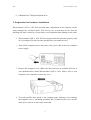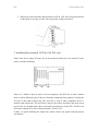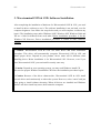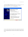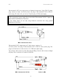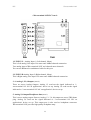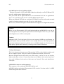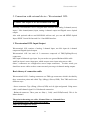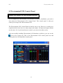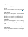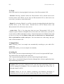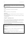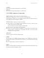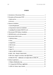
1
ESI
Waveterminal 192
INDEX
1. Introduction to Waveterminal 192X & 192L_____________________ 4
2. Hardware Installation ______________________________________ 6
1. System Requirement _______________________________________________ 6
2. Preparation for hardware installation ________________________________ 7
3. Installing Waveterminal 192X & 192L PCI card ________________________ 8
3. Waveterminal 192X & 192L Software Installation _______________ 10
4. Connection with external device - Waveterminal 192X ___________ 18
1. Waveterminal 192X Input/Output___________________________________ 18
5. Connection with external device - Waveterminal 192L ___________ 22
1. Waveterminal 192L Input/Output ___________________________________ 22
6. MI/ODI/O add-on card (sold separately) ______________________ 26
7. Waveterminal 192X Control Panel ___________________________ 29
1. Pull Down Menu _________________________________________________ 30
2. Clock___________________________________________________________ 31
3. Sample Rate _____________________________________________________ 31
4. Analog In _______________________________________________________ 31
5. DIGITAL IN – Digital Input selector ________________________________ 32
6. Digital Type –Digital format selector_________________________________ 33
7. Ana. IN/ Dig. IN – Input Level meter ________________________________ 33
8. OUT/MME –Output Level Adjust fader______________________________ 34
8. Waveterminal 192L Control Panel ___________________________ 35
1. Pull Down Menu _________________________________________________ 36
2. Clock___________________________________________________________ 37
3. Sample Rate _____________________________________________________ 37
4. Analog In _______________________________________________________ 37
2
ESI
Waveterminal 192
5. Digital IN – digital Input selector ___________________________________ 38
6. Digital Type –Digital format selector_________________________________ 39
7. MIC____________________________________________________________ 39
8. Ana. IN/ Dig. IN – Input Level meter ________________________________ 39
9. OUT/MME –Output Level Adjust fader______________________________ 40
9. Setting in Applications _____________________________________ 41
1. Windows Multimedia setup ________________________________________ 42
2. 5.1 channel for DVD Player application ______________________________ 42
3. ASIO 2.0- Cubase, Logic, Nuendo ___________________________________ 45
3. Sonar/Cakewalk _________________________________________________ 48
4. Sound Forge _____________________________________________________ 50
5. Wave Lab _______________________________________________________ 51
6. Giga Studio (v. 2.20.42 or higher) ___________________________________ 52
10. Specifications ___________________________________________ 53
Note
This manual handle both Waveterminal 192X and Waveterminal 192L.
Waveterminal 192X and 192L have similar features, functions, shape and also
same installing process. For the reason, we will explain about WT192 X & L
together.
Different parts of 192X & 192L will be explained with indication or separate
paragraph.
* All features and specifications subject to change without notice.
3
ESI
Waveterminal 192
1. Introduction to Waveterminal 192X & 192L
Thank you for choosing ESI Waveterminal 192X & 192L.
The Waveterminal 192X & 192L are Multimedia digital audio interfaces different from
other conventional sound cards. You will be amazed at the various and powerful
functions and features of Waveterminal 192X & 192L. Waveterminal 192X & 192L will
satisfy beginners who have just become involved in digital audio to professional
musicians produce music at the professional level with its various features and useful
functions. Especially, ‘Dolby Surround 5.1 channel’ will lead you to the true surround
experience.
1. Up to 192kHz sampling rate support
Waveterminal 192X and 192L are worlds leading 192kHz support digital recording
devices. The digital recording capability constantly progressed from 44.1kHz to 96kHz
and even up to 192kHz. Waveterminal 192X and 192L will prove their value in Multitrack Recording, Mastering or DVD Audio application.
2. Perfect compatibility with EWDM driver
Waveterminal 192X & 192L adopt the EWDM (Enhanced Audio MIDI driver model),
providing superior data processing and compatibility. Until now, Windows native
drivers such as MME, Direct Sound and the WDM driver could not show satisfied
performance for serious music production scene. Furthermore, Steinberg’s ASIO driver
and TASCAM’s GSIF drivers were not supported fully. Waveterminal 192X & 192L
employ the EWDM driver to provide the best solution for users in to take advantage
under newer Windows OS environment and concentrate on their work, not their system.
The E-WDM supports MME, ASIO, GSIF, and Direct X taking all the merits of these
drivers. One of its advantages is OS support that range from Windows 98SE and
Windows ME to Windows 2000 and XP, thus allowing the users to choose the OS of his
or her preference.
3. Professional Digital Recording Device
Waveterminal 192X & 192L are can be used for the beginners to professionals of harddisk recording application. The EWDM will work at its best in multi-track hard disk
recording. The Waveterminal 192X & 192L are fully compatible with multi-track
recording software such as Sonar/Cakewalk, Cubase, Logic and Nuendo; mastering
4
ESI
Waveterminal 192
software such as Sound Forge and Wave Lab; software sampler like GigaStudio, EXS
and Halion and most of Virtual Instruments such as Reason, Reactor.
4. Multimedia/5.1 channel surround device
Waveterminal 192X & 192L deliver super high-quality sound from Windows
multimedia tools with various additional features, which will be worth to replace the
soundcard in your computer. Waveterminal 192X & 192L are capable of playing back
MPEG, MP3, wav files, and playing DVD and Video CDs. As the Internet becomes
more and more popular, multimedia contents on the web is also useful, such as Flash
media and Internet Broadcast. Waveterminal 192X & 192L support all of these features
and, most importantly, 5.1 channel Dolby Surround format that will turn your computer
system into a DVD AV system better than expensive AV equipment for Hi-Fi users.
As the evolution of the computer system continues, digital audio is becoming more and
more common. With Waveterminal 192X & 192L, you can complete your Desk Top
Music Production System easily. Waveterminal 192X & 192L will be the center of your
DTMP system providing high quality sound which is not less than the quality of a
professional studio and a guide to the world of digital audio music and multimedia.
5
ESI
Waveterminal 192
2. Hardware Installation
Waveterminal 192X & 192L require 3-steps of installation: ‘PCI card installation’,
‘Driver installtion’, and finally ‘Connection with external device’. The ‘PCI card
installation’ step includes install the Waveterminal 192X & 192L PCI card into the PCI
slot. ‘Driver installation’ is having the operating system in your computer recognize
Waveterminal 192X & 192L and building the communication channel. In the
‘Connection with external device’ step, you will understand how to connect the
Waveterminal 192X & 192L to other devices such as MIC, Amp, mixer, and recording
devices such as an MD or DAT player.
1. System Requirement
To take advantage of Waveterminal 192X & 192L and their full capacity, the computer
specifications are very important. Even though Waveterminal 192X & 192L are built to
have low-CPU resource dependability, the computer needs to meet certain requirements
in order to get maximum performance. Waveterminal 192X & 192L are not just a
simple soundcard, but a multimedia digital audio device with various functions.
Therefore, the performance of Waveterminal 192X & 192L would be affected by the
computer specs that are required to process the vast amount of digital data. A faster
CPU, faster hard disk, and larger amounts of RAM are generally recommended.
Minimum System Requirement
1. Intel Pentium II 350 MHz CPU or higher
2. Mainboard with Intel chipsets
3. 64MB of RAM
4. One available PCI slot
5. Microsoft Windows 98SE/ME/2000/XP operating system
6. Ultra DMA 33 hard disk drive
Recommended System Requirement
1. Intel Pentium III CPU or higher
2. Motherboard with Intel series chipsets(BX,820,815 and so on)
3. More than 128MB of RAM
4. One available PCI slot
5. Microsoft Windows 98SE/ME/2000/XP operating system
6
ESI
Waveterminal 192
6. UDMA66/100 7200rpm hard disk drive
2. Preparation for hardware installation
Waveterminal 192X or 192L PCI card and other components in the computer can be
easily damaged by electrical shock. You need to use an anti-static device that can
discharge the static electricity of your body to avoid potential static damage to the cards.
1. Waveterminal 192X or 192L PCI card is placed into the anti static plastic pouch
as it is packaged. Do not open the pouch before you install the card.
2. Turn off the computer power and remove the power cable from your computer
power supply.
3. Remove the computer cover. Make sure that you have an available PCI slot in
your motherboard to install Waveterminal 192X or 192L. Please, refer to your
computer user’s manual to remove the cover.
4. To avoid possible static shock to the computer parts, discharge it by touching
the computer case or something grounded. We recommend you to use an antistatic device such as an anti-static wrist band.
7
ESI
Waveterminal 192
5. When you need to hold the Waveterminal 192X & 192L PCI card, please hold it
on the guide or he edge of card. Do not grab the card by the board.
3. Installing Waveterminal 192X & 192L PCI card
Please look for an empty PCI slot. If you do not know which one is an actual PCI slot,
please, read the following;
There are 3 kinds of slots in most of recent computers. The PCI slot is most common
and is used for different types of devices from the soundcard to the modem. Usually, the
PCI slot is the white-colored slot. The ISA slot is used in older computers and it is
marked with a black slot. The AGP slot is only for the video card and is the most recent
type of slot. It is marked with a brown slot and is located close to the CPU. It will be not
too hard to find the PCI slot for Waveterminal 192X & 192L.
If there is a guide blocking the empty slot, please remove the guide using the proper
screwdriver.
8
ESI
Waveterminal 192
Next, put the Waveterminal 192X & 192L PCI card into the slot and make sure it is
placed in the slot correctly. The card will fit into your slot and then tighten the screw.
Close the computer case.
9
ESI
Waveterminal 192
3. Waveterminal 192X & 192L Software Installation
After completing the installation of hardware for Waveterminal 192X & 192L, you need
to install its driver software to use it. The software installation is not too hard, even for
computer beginners. Just follow the steps below and you will complete it without any
hassel. The installation steps under Windows 98SE, Windows ME, Windows 2000 and
XP are a little bit different from each other. Below installation procedure is for the
Windows XP. However, Driver installation procedure is similar to other Windows
version.
* Caution: Waveterminal 192X & 192L use same driver and same installation
procedure. This driver will automatically recognize Waveterinal 192X & 192L and
install proper driver. Depend on your product, device name will be different when
installing driver. Below installation is for Waveterminal 192L. However, even if you
have Waveterminal 192X, you can install in exactly same way.
* Caution: Depend on your operating system, you may need Windows install CD.
You need to prepare Windows installation CD before the installation procedure begins.
* Caution: Because of the driver characteristic, Waveterminal 192X & 192L install
several drivers and continuously to reboot the system. However, select ‘cancel’ and just
keep going to install without rebooting. When all drivers are installed and Windows
doesn’t ask driver install any more, then restart the computer.
10
ESI
Waveterminal 192
1 Turn your computer’s main power on. Windows will automatically detect a new
device has been installed and “Found New Hardware Wizard” will appear.
Choose Install from a list or specific location and click next.
2. Choose ‘Search for the best driver in these locations’ and Specify the location of the
driver. Insert the provided Driver CD/diskette into the CD-Rom drive/ floppy disk drive
and select ‘Include this location in the search’ and click ‘Browse’ to find the accurate
location.
11
ESI
Waveterminal 192
12
ESI
Waveterminal 192
3. On Windows 2000 and XP, there might be this kind of message appeared. You
can simply ignore it and just select ‘Continue Anyway’.
13
ESI
Waveterminal 192
4. First Waveterminal 192X & 192L driver will be installed.
5. Windows will automatically install second driver. It’s same as above procedure.
14
ESI
Waveterminal 192
15
ESI
Waveterminal 192
6. Windows will continuously install from Waveterminal 192 EWDM Wave2 to Wave5.
And finally Windows will recognize and install ‘Waveterminal 192 EWDM Midi’.
Even though, several devices will be recognized and installed, just follow above step 1
~4. When your system keeps asking restart the computer, just ignore that and keep
going to install.
When all the drivers are installed and the system doesn’t ask driver install any more,
restart the computer.
7. After restart the windows, please confirm ‘M’ icon on the system tray.
16
ESI
Waveterminal 192
8. Restart your computer.
After rebooting, go to ‘My computer -> Control Panel -> System -> Device Manager’.
Check the devices under ‘Sound, video and game controllers’. If they are installed
correctly.
17
ESI
Waveterminal 192
4. Connection with external device - Waveterminal 192X
Caution: This chapter is for Waveterminal 192X only
Basically, Waveterminal 192X is a digital audio interface with analog 2 channel (stereo)
input, analog 6 channel output and Digital stereo Optical output.
Also with optional MI/ODI/O add-on card, you can add SPDIF Optical Input, SPDIF
Coaxial In/Out and 1 In/1 Out MIDI interface.
1. Waveterminal 192X Input/Output
Waveterminal 192X consists of analog 2 channel Input & 6 channel output and Digital
Optical output.
Waveterminal 192X has total of 5 connector composed of TRS(Tip/Ring/Sleeve)
connectors. 2 analog inputs are Balanced type input and they accept mono signal.
Other 3 connectors are configured as stereo output connectors. In other words, you
should use stereo cables to these connectors and you can get 6 channel analog outputs.
Caution: You can use Balanced or Unbalanced to Waveterminal 192X’s two Inputs.
However, WT192X’s 6 Outputs always have to be used Unbalanced.
Basic theory of connection cable
Waveterminal 192X’s 5 analog connectors use TRS type connector, which is divided by
three connection points and called Tip(+)/Ring(-)/Sleeve(GND). This TRS type
connector is used in two different ways.
- Stereo connector: Tip(+)/Ring(-)/Sleeve(GND) are left, right and ground. Using
stereo cable, send 2 channel signal. It’s Unbalanced connection.
- Balanced connector: Three parts are Hot(+), Cold(-) and GND(Ground). This is for
Mono channel.
The point is that using one cable, 2channel flows or 1 channel flows.
Waveterminal 192X’s two input port are mono.
And three outputs are stereo. Its mean Outputs are 6 channel.
18
ESI
Waveterminal 192
Waveterminal 192X’s two input ports use Balanced connection. Using TRS 55 phone
plug, connect as mono. As below picture, the plug to Waveterminal 192X is TRS 55
phone plug. The other side, you can use 55 phone plug or XLR(cannon)plug.
* This connection is mono signal flows in one cable. Waveterminal 192X’s 2 inputs are
mono channel and Balanced connection.
* Two analog Inputs are not only using balanced connection also using general
Unbalanced connection.
.
Waveterminal 192X’s output port use Y cable (stereo ↔mono x 2).
As below picture, the plug to Waveterminal 192X is TRS 55 stereo phone plug. The
plug to external mixer or other devices is 2 x TRS mono phone plug.
Tip of Stereo cable connect to Left white plug and Ring of stereo cable connect to Right
red plug. Sleeve connects to Ground of both sides.
19
ESI
Waveterminal 192
<Waveterminal 192X PCI card>
1. LINE IN L – Analog Input 1 (Left channel, Mono)
This is Left analog Line input. It is mono and +4dBu balanced connection.
Two analog input of Waveterminal 192X are balanced mono channels.
You can use Balanced or unbalanced cable for this port.
2. LINE IN R-Analog Input 2 (Right channel, Mono)
This is Right analog Line input. It is mono and +4dBu balanced connection.
3. 4. Analog 1,2/3,4 Output (stereo)
These are stereo Analog Outputs. Analog 1,2 send out the signal indicated as ‘1waveterminal 192 2ch’ on application’s device set up. Analog 3,4 send out the signal
indicated as ‘2-waveterminal 192 2ch’ on application’s device set up.
5. Analog 5,6 Output/Headphone Out(stereo)
This is stereo analog output. Same as Analog 1 2 / 3 4, this output use stereo TRS phone
plug. Analog 5,6 send out the signal indicated as ‘3-waveterminal 192 2ch’ on
application’s device set up. This output port is also used as headphone connector.
Waveterminal 192X provides high quality headphone amp.
20
ESI
Waveterminal 192
6. SPDIF Optical Out/AC3(Dolby digital)
This port can transfer 192X’s audio data without loss directly to an DAT, MD and CDrecorder, which support digital connection.
This port sends out the signal indicated as ‘4-waveterminal 192 2ch’ on application’s
device set up and also sends out AC3 encoded Dolby Digital signal.
When you playback DVD title on a software DVD player, you can easily make surround
sound environment using the port and AV receiver with decoder.
In this case, software DVD player and DVD title must support AC3 digital thru function.
Caution:
When you use Waveterminal 192X with Optional add-on card MI/ODI/O, you can get
not only Optical out, also Optical input and Coaxial In/Output. In this case, you need to
select Digital out on 192X’s control panel.
Caution:
Although 192X’s Tos-Link Optical I/O port can’t support 192kHz in specification, we
got the reports shows possibility while we were testing. However, it heavily depends on
system environment, It may have problem on over 100kHz sample rate. You have to use
high quality Optical cable otherwise you may get loss of data or distortion.
7.8. Sync In/Out port
This is for using more than one more Waveterminal 192X or other digital recording card
in one computer system. This port is used for synchronize between your devices.
Because all digital devices have their own clock source, you have to set one clock as
Master and others as slave. Connect from Sync out of Master clock card to Sync In of
slave card. In Master clock card, set clock source as ‘Internal’. Slave card should set as
‘card sync’.
9 MI/ODI/O connector (sold separately)
This connector is for connecting MI/ODI/O add-on card.
MI/ODI/O add-on card makes Waveterminal 192X a total of 4 in 8out Audio / 16 MIDI
channel integrated audio interface.
21
ESI
Waveterminal 192
5. Connection with external device - Waveterminal 192L
Caution: This chapter is for Waveterminal 192L only
Basically, Waveterminal 192L is a digital audio interface with analog 2 channel (stereo)
input, 1 Mic channel(mono) input, analog 6 channel output and Digital stereo Optical
output.
Also with optional add-on card MI/ODI/O add-on card, you can add SPDIF Optical
Input, SPDIF Coaxial In/Out and 1 In/1 Out MIDI interface.
1. Waveterminal 192L Input/Output
Waveterminal 192L consists of analog 2 channel Input, one Mic input & 6 channel
output and Digital Optical output.
Waveterminal 192L has total of 5 connectors composed of TRS(Tip/Ring/Sleeve)
connectors.
MIC input is Balanced type input. So you need to use general Balanced Mic cable.
And Line input is stereo input port, which accepts stereo input using stereo cable.
Other 3 connectors are configured as stereo output connectors. In other words, you
should use stereo cables to these connectors and you can get 6 channel analog outputs.
Basic theory of connection cable
Waveterminal 192L’s 5 analog connectors use TRS type connectors which is devided by
three connection points and called Tip(+)/Ring(-)/Sleeve(GND). This TRS used in two
different ways.
- Stereo connector: Tip(+)/Ring(-)/Sleeve(GND) are left, right and ground. Using stereo
cable, send 2channel signal. It’s Unbalanced connection.
- Balanced connector: Three parts are Hot(+), Cold(-) and GND(Ground). This is for
Mono channel.
The point is that using one cable, 2channel flows or 1 channel flows.
Waveterminal 192L’s MIC input port is mono.
And Line in/outputs are stereo.
22
ESI
Waveterminal 192
Waveterminal 192L’s MIC input port use traditional Balanced cable. As below picture,
the plug to Waveterminal 192L is TRS 55 phone plug. The plug to Microphone is XLR.
.
Waveterminal 192L’s output port use Y cable(stereo ↔mono x 2).
As below picture, the plug to Waveterminal 192L is TRS 55 stereo phone plug. The plug
to external mixer or other devices is 2 x TRS mono phone plug.
Tip of Stereo cable connect to Left white plug and Ring of stereo cable connect to Right
red plug. Sleeve connects to Ground of both sides.
23
ESI
Waveterminal 192
<Waveterminal 192L PCI card>
1. MIC IN
This is MIC input of Waveterminal 192L. You can use dynamic or condenser
microphone and it supplies +12V DC phantom power. You cannot use MIC input and
Line input at the same time. You can choose MIC input or Line input on the control
panel of 192L.
When you use condenser MIC, you can turn on/off phantom power switch on the
control panel.
2. LINE IN -Analog Input(stereo)
This is analog Line input. It is stereo +4dBu Unbalanced connection. You cannot use
this Line input and MIC input at the same time.
3. 4. Analog 1,2/3,4 Output (stereo)
These are stereo Analog Outputs. Analog 1,2 send out the signal indicated as ‘1waveterminal 192 2ch’ on application’s device set up. Analog 3,4 send out the signal
indicated as ‘2-waveterminal 192 2ch’ on application’s device set up. Using TRS 55
phone plug, send two signal from one output port.
24
ESI
Waveterminal 192
5. Analog 5,6 Output/Headphone Out (stereo)
This is stereo analog output. Same as Analog 1 2 / 3 4, this output use stereo TRS phone
plug. Analog 5,6 send out the signal indicated as ‘3-waveterminal 192 2ch’ on
application’s device set up. This output port is also used as headphone connector.
Waveterminal 192L provides high quality headphone amp.
6. SPDIF Optical Out/AC3(Dolby digital)
This port can transfer 192L’s audio data without loss, directly to a DAT, MD, CDrecorder, which support digital connection.
This port sends out the signal indicated as ‘4-waveterminal 192 2ch’ on application’s
device set up, and also sends out AC3 encoded Dolby Digital signal.
When you playback DVD title on a software DVD player, you can easily make surround
sound environment using the port and AV receiver with decoder.
In this case, software DVD player and DVD title must support AC3 digital thru function.
Caution:
When you use Waveterminal 192L with Optional add-on card MI/ODI/O, you can get
not only Optical out, also Optical input and Coaxial In/Output. In this case, you need to
select Digital out on 192L’s control panel.
Caution:
Although 192L’s Tos-Link Optical I/O port can’t support 192kHz in specification, we
got the reports shows possibility while we were testing. However, it heavily depends on
system environment, It may have problem on over 100kHz sample rate. You have to use
high quality Optical cable otherwise you may get loss of data or distortion.
7. MI/ODI/O connector (sold separately)
This connector is for connecting optional MI/ODI/O add-on card.
MI/ODI/O add-on card makes Waveterminal 192L a total of 4 in 8out Audio / 16 MIDI
channel integrated audio interface.
25
ESI
Waveterminal 192
6. MI/ODI/O add-on card (sold separately)
Caution: MI/ODI/O add-on card is not included in Waveterminal 192X & 192L.
It’s sold separately.
The MI/ODI/O has one Coaxial Input/Output, one Optical digital Input and 16 channels
MIDI Input/Output.
The MI/ODI/O is designed to be used with the Waveterminal 192 series of audio cards
as an add-on. It’s easy to install and does not require any additional power supply or
drivers to install. No new IRQ set up involved.
The MI/ODI/O lets you get more from your Waveterminal 192X or 192L by adding
the power of S/PDIF In and Out and MIDI I/O.
MI/ODI/O driver already included in EWDM driver of Waveterminal 192X and 192L.
Therefore, by the installation of the driver of Waveterminal 192X & 192L, you can use
MI/ODI/O right away.
Just hook it up to your Waveterminal 192 card like a below picture and you're ready to
go!
26
ESI
Waveterminal 192
1. SPDIF Optical Input (24bit/96kHz)
Using this Optical input port with Waveterminal 192X & L’s Optical output, you can
use Optical In/Out with external device.
Caution:
Although MI/ODI/O’s Tos-Link Optical I/O port can’t support 192kHz in specification,
we got the reports shows possibility while we were testing. However, it heavily depends
on system environment, It may have problem on over 100kHz sample rate. You have to
use high quality Optical cable otherwise you may get loss of data or distortion.
2. External connector port
This port is for connecting MI/ODI/O add-on card to Waveterminal 192 series.
MI/ODI/O add-on card makes Waveterminal 192L a total of 4 in 8out Audio / 16 MIDI
channel integrated audio interface.
This port is connecting for the exclusive external connection cable. This cable is
provided with the MI/ODI/O.
As next picture, the cable consists of total of 5 connectors. On one end, there is an 8-pin
connector to MI/ODI/O. The other end, there are two small connectors for SPDIF
digital In/Out port and large connectors for MIDI interface In/Out. These 4 cables are
labeled for easier distinction.
27
ESI
Waveterminal 192
3. Connector for Waveterminl 192 series
Using provided cable, connect MI/ODI/O and Waveterminal 192X & 192L.
4. 5. In, Out – MIDI In/Out display
When MIDI signal flows through MI/ODI/O, This LED will be blinking.
6. PWR
It is MI/ODI/O power LED(Indicator). When connect MI/ODI/O on your computer and
turn on computer, this LED will lit.
28
ESI
Waveterminal 192
7. Waveterminal 192X Control Panel
Caution: This chapter is for Waveterminal 192X only
If you complete the Waveterminal 192X hardware driver installation, you need to learn
about the Waveterminal 192X Control Panel. This control panel is what you control
your setup for the Waveterminal 192X.
The Waveterminal 192X Control Panel is built for easy to use. However, it could give a
complicated look since there are many inputs and outputs. All input and output controls
are the same. So, if you learn about one control, you can use the others easily.
After successfully installing Waveterminal 192X hardware and driver, you can see the
icon on the system tray. It is the Waveterminal 192X control panel icon and clicking
on this icon will launch the control panel.
29
ESI
Waveterminal 192
1. Pull Down Menu
The Waveterminal 192X control panel includes a pull down menu bar that contains the
configuration menus for the Control Panel.
1. File - Exit
File – Exit will close the Waveterminal 192X Control Panel window but it will not shut
down the Control Panel. You can always launch the Control Panel by clicking
on the system tray.
icon
2. Config – Mouse Wheel
Mouse Wheel will control the mouse wheel adjustment. When you use the mouse wheel
to adjust the volume level, the adjustment step is set to ±1.5dB as default. You can
configure the adjustment steps to your preference.
- Step 1: When you move the mouse wheel one step, the fader will move by ±1.5dB.
- Step 2: When you move the mouse wheel one step, the fader will move by ±3.0dB.
- Step 4: When you move the mouse wheel one step, the fader will move by ±6.0dB.
- Step 8: When you move the mouse wheel one step, the fader will move by ±12.0dB.
3. Config – Latency
This will decide the latency of the Waveterminal 192X. You have to set proper latency
depends on your situation. Generally, higher latency is fit for Multi-track recording
software using multiple tracks. Process time maybe longer, but it’s stable. Lower latency
is fit for software synthesizer, mastering software or Multi-track software using only
few tracks.
4. Config – Factory Default
This returns all the Waveterminal 192X configurations to factory default setting.
5. Config - Always On Top
This will set the Waveterminal 192X control panel to always over other Windows. If
this is not selected, the active windows will be set over the Waveterminal 192X Control
Panel.
6. Config - Card
In the case of using two or more Waveterminal 192X in one computer system, this
30
ESI
Waveterminal 192
button shows you status of control panel of each card.
For example, if you choose CARD2, The control panel becomes second card’s control
panel.
2. Clock
Select this menu for choosing digital clock source of the Waveterminal 192X.
- Internal: Selecting ‘Internal’ makes the Waveterminal 192X’s internal clock and it
becomes master clock. When you use only one Waveterminal 192X or other device was
set as slave, you have to choose this mode.
- Digital: By selecting ‘Digital’ you will be using the incoming digital audio data from
external device as the clock source. External device will be Master device and
Waveterminal 192X will become slave device.
- CARD SYNC: This is for using more than one more Waveterminal 192X in one
computer system. Because all digital devices have their own clock source, you have to
set one clock as Master and others as slave. Connect from Sync out of Master clock card
to Sync In of slave card. In Master clock card, set clock source as ‘Internal clock’.
Slave card should set as this ‘card sync’. You can connect two cards using 2 pin sync
cable of Waveterminal 192X.
3. Sample Rate
Auto: Selecting ‘Auto’ sets sample rate automatically according to your audio file’s
sample rate.
Lock: In this mode, you can set sample rate manually.
4. Analog In
This is where you can set input monitoring of 192X’s two analog Input.
192X’s input monitoring function is real-time monitoring through hardware.
That’s why we recommend using the function although other software applications have
Input monitoring function too.
31
ESI
Waveterminal 192
Caution: When you select ‘Monitor & H.P.’ and start input monitoring, Output 5,6 will
be changed as Headphone out. You can monitor same signal out of Line Out 1,2 through
Output 5,6(H.P)
Caution: Please do not use software monitoring and hardware monitoring in
simultaneously.
You can’t get accurate monitoring and it may causes flange effect.
Caution: It is not affect on recording in software. Regardless of this button, you can
record in software safely.
Monitor H.P
When you select this button, Analog Input signals goes to Output 1,2 and Output 5,6 is
changed as Headphone out.
You can monitor Input signal in real-time. You can monitor same signal out of Output
1,2 through Output 5,6.
5. DIGITAL IN – Digital Input selector
When you connect Waveterminal 192X with MI/ODI/O add-on card (sold separately),
you can get Optical and Coaxial Input. You can select between two digital connectors
here and turn on and turn off the selected input monitoring.
192X’s input monitoring function is real-time monitoring and processing in hardware.
That’s why we recommend using this function although other software applications may
have Input monitoring function too.
Caution: When you select ‘Monitor & H.P.’ and start input monitoring, Output 5,6 will
be changed as Headphone. You can monitor same signal out of Line Out 1,2 through
Output 5,6(H.P)
Caution: Please do not use software monitoring and hardware monitoring in
simultaneously.
You can’t get accurate monitoring and it may causes flange effect.
32
ESI
Waveterminal 192
Caution: It is not affect on recording in software. Regardless of this button, you can
record in software safely.
1. Coaxial
When you connect WT192X with MI/ODI/O, you can select MI/ODI/O’s Coaxial Input
as digital input.
2. Optical
When you connect WT192X with MI/ODI/O, you can select MI/ODI/O’s Optical Input
as digital input.
3. MONITOR & H.P
When you select this button, Digital Input signals goes to Output 1,2. Also Output 5,6 is
changed to Headphone out.
You can monitor Digital input signal in real-time. You can monitor same signal out of
Output 1,2 through Output 5,6.
6. Digital Type –Digital format selector
When you use WT192 with MI/ODI/O together, this is where you to set various digital
format.
1. Pro (IEC 958 Type 1)
WT192X’s digital in/out format is AES/EBU.
2. Consumer (IEC 958 Type II)
WT192X’s digital in/out format is S/PDIF.
7. Ana. IN/ Dig. IN – Input Level meter
1. Ana. IN
This is where to display Analog Input Level of WT192X.
2. Dig. IN
This is where to display Digital Input Level of WT192X.
33
ESI
Waveterminal 192
8. OUT/MME –Output Level Adjust fader
1. OUT 1,2 3,4 5,6 – When you don’t use input monitoring.
Output goes to Output port 1,2 3,4 5,6 directly as you set on your application.
Click and drag to change Level. The numbers of bottom show the relative amount of
level in dB. If you click, it changes to ‘MUTE’.
2. OUT 1,2 3,4 5,6 – When you use input monitoring
1,2: Wave source of 1,2 as setting on your application. Also this is where you can
monitor input and it will display ‘MON’.
However Input level can’t be adjusted with this fader.
3,4: Wave source of 3,4 as setting on your application.
5,6: Output 5,6 port/fader changes to Headphone port/fader and you can monitor same
signal of Output 1,2 through 5,6. It will display ‘HP-VOL’. You can also adjust
Headphone level using this fader.
3. DIG OUT
It’s the Level meter of WT192X’s Digital output.
4. MME
You can adjust level of MME supporting software in here. MME driver output level
sometimes lower than it’s actual output level. In this case, you should adjust level using
this fader. The ‘%’ of bottom means volume level indication.
5. Mute
When you click the number on bottom of each fader, selected fader will be muted. And
the number on bottom is changed to display ‘Mute’.
34
ESI
Waveterminal 192
8. Waveterminal 192L Control Panel
Caution: This chapter is for Waveterminal 192L only
If you complete the Waveterminal 192L hardware and driver installation, you need to
learn about the Waveterminal 192L Control Panel. This control panel is what you
control your setup for the Waveterminal 192L.
The Waveterminal 192L Control Panel is built for easy to use. However, it could give a
complicated look since there are many inputs and outputs. All input and output controls
are the same. So, if you learn about one control, you can use the others easily.
After successfully installing Waveterminal 192L hardware and driver, you can see the
icon on the system tray. This is the Waveterminal 192L control panel icon and
clicking this icon will launch the control panel.
35
ESI
Waveterminal 192
1. Pull Down Menu
The Waveterminal 192L control panel includes a pull down menu bar that contains the
configuration menus for the Control Panel.
1. File - Exit
File – Exit will close the Waveterminal 192L Control Panel window but it will not shut
down the Control Panel. You can always launch the Control Panel by clicking
on the system tray.
icon
2. Config – Mouse Wheel
Mouse Wheel will control the mouse wheel adjustment. When you use the mouse wheel
to adjust the volume level, the adjustment step is set to ±1.5dB as default. You can
configure the adjustment steps to your preference.
- Step 1: When you move the mouse wheel one step, the fader will move by ±1.5dB.
- Step 2: When you move the mouse wheel one step, the fader will move by ±3.0dB.
- Step 4: When you move the mouse wheel one step, the fader will move by ±6.0dB.
- Step 8: When you move the mouse wheel one step, the fader will move by ±12.0dB.
3. Config – Latency
This will decide the latency of the Waveterminal 192L. You have to set proper latency
depends on your situation. Generally, higher latency is fit for Multi-track recording
software using multiple tracks. Process time maybe longer, but it’s stable. Lower latency
is fit for software synthesizer, mastering software or Multi track software using only
few tracks.
4. Config – Factory Default
This returns all the Waveterminal 192L configurations to factory default setting.
5. Config - Always On Top
This will set the Waveterminal 192L control panel to always over other Windows. If this
is not selected, the active windows will be set over the Waveterminal 192L control panel.
6. Config – Card (This section is for future use)
36
ESI
Waveterminal 192
2. Clock
Select this menu for choosing digital clock source of the Waveterminal 192L
- Internal: Selecting ‘Internal’ makes the Waveterminal 192L’s internal clock and it
becomes master clock. When you use only one Waveterminal 192L or other device was
set as slave, you have to choose this mode.
- Digital: By selecting ‘Digital’ you will be using the incoming digital audio data from
external device as the clock source. External device will be Master device and
Waveterminal 192L will become slave device.
- CARD SYNC: This is for using more than one more Waveterminal 192L in one
computer system. Because all digital devices have their own clock source, you have to
set one clock as Master and others as slave. Connect from Sync out of Master clock card
to Sync In of slave card. In Master clock card, set clock source as ‘Internal clock’.
Slave card should set as this ‘card sync’. You can connect two cards using 2 pin sync
cable of Waveterminal 192L.
3. Sample Rate
Auto: Selecting ‘Auto’ sets sample rate automatically according to your audio file’s
sample rate.
Lock: In this mode, you can set sample rate manually.
4. Analog In
This is where you can set input monitoring of 192L’s stereo Line input and MIC input.
You cannot choose two inputs at the same time.
192L’s input monitoring function is real-time monitoring through hardware.
That’s why we recommend using the function although other software applications have
Input monitoring function too.
Caution: When you select ‘Monitor & H.P.’ and start input monitoring, Output 5,6
will be changed as Headphone. You can monitor same signal out of Line Out 1,2
through Output 5,6(H.P)
Caution: Please do not use software monitoring and hardware monitoring in
simultaneously. You can’t get accurate monitoring and it may causes flange effect.
37
ESI
Waveterminal 192
Caution: It is not affect on recording in software. Regardless of this button, you can
record in software safely.
1. LINE
When you select this button, 192L accepts stereo LINE Input.
2. MIC
When you select this button, 192L accepts MIC Input.
3. Monitor H.P
When you select this button, Analog Input signals goes to Output 1,2 and Output 5,6 is
changed to Headphone out.
You can monitor Input signal in real-time. You can monitor same signal out of Output
1,2 through Output 5,6.
5. Digital IN – digital Input selector
When you connect Waveterminal 192L with MI/ODI/O add-on card(sold separately),
you can get Optical and Coaxial Input. You can select between two digital connectors in
here and turn on and turn off the selected input monitoring.
192L’s input monitoring function is real-time monitoring and processing in hardware.
That’s why we recommend using this function although other software applications may
have Input monitoring function too.
Caution: When you select ‘Monitor & H.P.’ and start input monitoring, Output 5,6 will
be changed as Headphone. You can monitor same signal out of Line OUT 1,2 through
Output 5,6(H.P)
Caution: Please do not use software monitoring and hardware monitoring in
simultaneously.
You can’t get accurate monitoring and it may causes flange effect.
Caution: It is not affect on recording in software. Regardless of this button, you can
record in software safely.
38
ESI
Waveterminal 192
1. Coaxial
When you connect WT192L with MI/ODI/O, you can select MI/ODI/O’s Coaxial Input
as digital input.
2. Optical
When you connect WT192L with MI/ODI/O, you can select MI/ODI/O’s Optical Input
as digital input.
3. MONITOR & H.P
When you select this button, Digital Input signals goes to Output 1,2. Also Output 5,6 is
changed to Headphone out.
You can monitor Digital input signal in real-time. You can monitor same signal out of
Output 1,2 through Output 5,6.
6. Digital Type –Digital format selector
When you use WT192L with MI/ODI/O together, this is where you to set various digital
format.
1. Pro (IEC 958 Type 1)
WT192L’s digital in/out format is AES/EBU.
2. Consumer (IEC 958 Type II)
WT192L’s digital in/out format is S/PDIF.
7. MIC
This is where you to set 192L’s MIC Input. You can adjust level or select Phantom
power.
1. Level fader
You can adjust level of MIC input.
2. +12V
When you use Condenser Microphone, you need phantom power.
WT192L provides +12V Phantom power.
If you use Dynamic Microphone, please turn off this button.
8. Ana. IN/ Dig. IN – Input Level meter
39
ESI
Waveterminal 192
1. Ana. IN
This is where to display Analog Input Level of WT192L.
2. Dig. IN
This is where to display Digital Input Level of WT192L.
9. OUT/MME –Output Level Adjust fader
1.OUT 1,2 3,4 5,6 – When you don’t use input monitoring.
Output goes to Output port 1,2 3,4 5,6 as you set on your application.
Click and drag to change Level. The numbers of bottom show the relative amount of
level in dB. If you click, it changes to ‘MUTE’.
2. OUT 1,2 3,4 5,6 – When you use input monitoring
1,2: Wave source of 1,2 as setting on your application. Also this is where you can
monitor input and it will display ‘MON’.
However Input level is can’t be adjusted with this fader.
3,4: Wave source of 3,4 as setting on your application.
5,6: Output 5,6 port/fader changes to Headphone port/fader and you can monitor same
signal of Output 1,2 through 5,6. It will display ‘HP-VOL’. You can also adjust
Headphone level using this fader.
3. DIG OUT
It’s the Level meter of WT192L’s Digital output.
4. MME
You can adjust level of MME supporting software in here. MME driver output level
sometimes lower than it’s actual output level. In this case, you should adjust level using
this fader.
The ‘%’ of bottom means volume level indication.
5. Mute
When you click the number on bottom of each fader, selected fader will be muted. And
the number on bottom is changed to ‘Mute’.
40
ESI
Waveterminal 192
9. Setting in Applications
Waveterminal 192X & 192L are premium multimedia audio device designed to be used
for professional audio work in a Windows environment. It has a wide range of usage
from game sound to DVD surround sound. It is very easy to set up the WT192X &
192L in the multimedia setup of the windows control panel. Also the WT192X & 192L
can be used with digital audio software to perform hard disk recording. This chapter
includes set up guide for some common software. Especially, WT192X & 192L uses the
EWDM driver that supports the audio dedicated drivers such as WDM, MME, ASIO,
GSIF and Direct Sound.
This chapter only contains the basic setup for some of the software. For more detailed
info, please refer to the manual of the software.
Driver name and Output
1. Waveterminal 192 2ch
Analog Output 1,2
2. Waveterminal 192 2ch
Analog Output 3,4
3. Waveterminal 192 2ch
Analog Output 5,6
4. Waveterminal 192 SPDIF-AC3
Digital Output
5. Waveterminal 192 5.ch
Analog Output 1~6 Surround output
41
ESI
Waveterminal 192
1. Windows Multimedia setup
The Windows Multimedia setup is required to use WT192X &192L as the sound system
for Windows multimedia applications.
Go to ‘My computer-> Control Panel -> Sounds and Audio Device Properties -> Audio
tab. Select WT192 driver as your playback device.
2. 5.1 channel for DVD Player application
( Ex. Power DVD )
WT192X &192L can be used with 5.1 channel DVD software player to provide 5.1
channel analog surround sound. Since WT192X and 192L is built for professional audio,
it will deliver optimal sound for your DVD player. You can configure WT192X & 192L
easily to use it for surround sound.
Go to ‘My computer-> Control Panel -> Sounds and Audio Device Properties -> Audio
tab. Select ‘5-Waveterminal 192 5.1 ch’ driver as your playback and Recording device.
42
ESI
Waveterminal 192
* You must check “DMA” in your DVD-Rom drive settings. IF you don’t check
DMA, you cannot attain a crisp picture.
On the Power DVD main applet, click the right mouse button, and choose
‘Configuration.’
Select ‘6 Speaker Output’. Now you can enjoy DVD with 5.1 channel surround sound.
43
ESI
Waveterminal 192
Caution: This is 5.1 channel surround sound route
This order will be varied by your operating systems.
Waveterminal
192 Output
1
2
3
4
Speaker
Front
Left
Front
Right
Center
Woofer
5
6
Surround Surround
Left
Right
Caution. When you use 5.1 channel surround, you have to turn off ‘Input Monitor’.
44
ESI
Waveterminal 192
3. ASIO 2.0- Cubase, Logic, Nuendo
-Cubase
After launching Cubase, go to ‘System’ under ‘Audio’ menu. Select ‘ASIO 2.0 –
Waveterminal 192’ for the ASIO device and ‘Waveterminal 192 Clock’ for the Audio
clock source.
45
ESI
Waveterminal 192
-Nuendo
After launching Nuendo, go to Device -> Device setup ->VST Multitrack. Select ‘ASIO
2.0 –Waveterminal 192’ for the ASIO device and ‘Waveterminal 192 Clock’ for the
Audio clock source.
-Logic
After launching Logic, go to Preference -> Audio Drivers2. Check the ‘ASIO’ and
select ‘ASIO 2.0 –Waveterminal 192’.
46
ESI
Waveterminal 192
And go to ‘Synchronisation’ -> ‘MIDI’ and uncheck ‘Transmit MIDI Clock’ for better
performance.
47
ESI
Waveterminal 192
3. Sonar/Cakewalk
Before you using Sonar, you have to do several setting first.
You have to set proper latency on the control panel of 192X & 192L.
After launching sonar, Go to ‘Option’ -> Audio and select ‘Wave Profiler’ of ‘General’
tab. Unless Sonar can’t recognize buffer of 192X & 192L.
In the case of Sonar:
Like a next picture, select ‘Waveterminal 192 5.1 ch 1~8’ for using WDM driver.
Do not select 2 ch driver.
In the case of Cakewalk:
Cakewalk has to use MME driver, therefore select ‘Waveterminal 192 2 ch’ driver.
48
ESI
Waveterminal 192
49
ESI
Waveterminal 192
4. Sound Forge
In Sound Forge, select ‘Option’ from menu bar. Select ‘Preference…’ then Wave tab.
Choose ‘Waveterminal 192 2ch’ as Playback and Record device.
50
ESI
Waveterminal 192
5. Wave Lab
In Wave Lab, Go to Option -> Preferences -> Audio Card.
Choose ‘Waveterminal 192 2ch’ as Playback and Record device.
51
ESI
Waveterminal 192
6. Giga Studio (v. 2.20.42 or higher)
If you want to use Waveterminal 192X & 192L with Giga Studio, you have to use Giga
Studio v.2.20.42 or higher.
Caution: If you want to use Giga Studio in Windows 2000 or XP, you need to use Giga
Studio v.2.5.
Set as below picture.
52
ESI
Waveterminal 192
10. Specifications
1. Waveterminal 192X
1. Input type : Analog Line_In - 2 Channel (1/4" TRS phone Plug)
2. Output Type : Analog Out - 6 Channel(3 Stereo 1/4" TRS phone Plug)
Digital Out - Optical Out (TOS-LINK)
3. Input LEVEL : +4dBu balanced, +4dBu Nominal, +22.5dBu Max
4. Output LEVEL : +4dBu Unbalanced, +4dBu Nominal, +16.5dBu Max
5. Input Impedance : 10K ohm
6. Output Impedance : 100 ohm
7. Output Attenuation : Digital -127dB ~ 0dB, 0.5dB Step Size(with Mute)
8. A/D Spec
1) Sampling Rate : 16, 22, 24, 32, 44.1, 48, 88.2, 96, 176.4, 192 KHz
2) Dynamic Range (S/N)
: 123dB A-Weighted (Typical)
3) Frequency Response
: 20 ~ 21.768KHz (@ fs=48KHz)
4) Resolution
: 24 Bits
9. D/A Spec
2) Sampling Rate : 16, 22, 24, 32, 44.1, 48, 88.2, 96, 176.4, 192 KHz
2) Dynamic Range (S/N)
: 106dB A-Weighted (Typical)
3) Frequency Response
: 20 ~ 21.768KHz (@ fs=48KHz)
4) Resolution
: 24 Bits
10. Digital Out Spec
1) Type
: Optical connector (TOS-LINK)
2) Format
: IEC-958 Consumer(S/PDIF), IEC-958
Professional(AES/EBU)
3) Sample Rate
: 16, 22, 24, 32, 44.1, 48, 88.2, 96 kHz
4) Resolution
: 24 Bits
11. Headphone Amp Spec
1) Output Power
: 60mW Max
2) Signal to Noise Ratio: 110dB (Typical)
3) (THD+N)/S
: -70dB, 0.03% (Typical)
53
ESI
Waveterminal 192
2. Waveterminal 192L
1. Input type : Analog Mic_IN - 1 Channel(1/4" TRS phone plug)
Analog Line_In - 2 Channel (Stereo 1/4" TRS phone Plug)
2. Output Type : Analog Out - 6 Channel (3 Stereo 1/4" TRS phone Plug)
Digital Out - Optical Out (TOS-LINK)
3. Input LEVEL
+4dBu Unbalanced, +4dBu Nominal, +17dBu Max
4. Output LEVEL +4dBu Unbalanced, +4dBu Nominal, +16.5dBu Max
5. Input Impedance : Mic in 10K ohm
Line in 10K ohm
6. Output Impedance : 100 ohm
7. Output Attenuation : Digital -96dB ~ 0dB, 0.75dB Step Size(with Mute)
8. A/D Spec
1) Sampling Rate : 16, 22, 24, 32, 44.1, 48, 88.2, 96 KHz
2) Dynamic Range (S/N)
: 100 dB A-Weighted (Typical)
3) Frequency Response
: 20 ~ 22.5KHz (@ fs=48kHz)
4) Resolution
: 24 Bits
9. D/A Spec
2) Sampling Rate : 16, 22, 24, 32, 44.1, 48, 88.2, 96, 176.4, 192 KHz
2) Dynamic Range (S/N)
: 104dB A-Weighted (Typical)
3) Frequency Response
: 20 ~ 22.5KHz (@ fs=48kHz)
4) Resolution
: 24 Bits
10. Digital Out Spec
1) Type
: Optical connector (TOS-LINK)
2) Format
: IEC-958 Consumer(S/PDIF),
IEC-958 Professional(AES/EBU)
3) Sampling Rate : 16, 22, 24, 32, 44.1, 48, 88.2, 96 KHz
4) Resolution
: 24 Bits
11. Mic PreAmp Spec
1) Mic Input Gain : +25dB Fix and 0dB ~ 22.5dB Variable
(1.5dB Step Size)
2) Phantom Power : +12V Phantom Power
12. Headphone Amp Spec
1) Output Power
: 60mW Max
2) Signal to Noise Ratio: 110dB (Typical)
3) (THD+N)/S
: -70dB, 0.03% (Typical)
54
ESI
Waveterminal 192
3. MI/ODI/O
1. MIDI Interface
1) 16 Channel MIDI In/Out Interface
2. Coaxial Digital In/Out Spec
1) Format
: IEC-958 Consumer(S/PDIF),
IEC-958 Professional(AES/EBU)
2) Sample Rate
: 16, 22, 24, 32, 44.1, 48, 88.2, 96,
176.4(192X only), 192 KHz
3) Resolution
: 24 Bits
3. Optical Digital In Spec
1) Format
: IEC-958 Consumer(S/PDIF),
IEC-958 Professional(AES/EBU)
2) Sample Rate
: 16, 22, 24, 32, 44.1, 48, 88.2, 96 KHz
3) Resolution
: 24 Bits
4. LED Signal Display
1) MIDI In
: Green
2) MIDI Out
: Yellow
3) Power
: Red
55