1
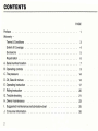
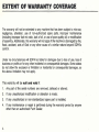
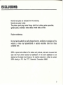
Dear Puch Owner
This is your riding, maintenance and warranty guide. By following the instructions
described in this booklet, we at Puch know you will enjoy many miles of pleasurable
Moped Riding.
Should a need ever exist for parts or service, simply contact your Puch dealer. He also
has available for your purchase a Service Manual under the partNr. 907.2.71 .894.5 0180
Thank you for joining the Puch family, please ride safely and have fun.
P.O. BOX 7777
Greenwich, Ct. 06830
CONTENTS
PAGE
Preface . . .. . .. .
WarrantyTerms & Conditions
Extent of Coverage
3
4
Exclusions
5
Registration . . . .
6
A. Serial number location
7
B. Operating controls
C. Tire pressure
9
. . . .
D . Oil, Gas/oil mixture
.
14
14
E. Operating instruction
17
F. Riding instruction
20
..
G. Trouble shooting
21
H. Owner maintenance
I. Suggested maintenance and lubrication chart
23
25
J. Consumer information
26
2
THE WARRANTY- Terms & Conditions
Subject to the terms set forth below, the Puch motorized bicycle is warranteed to be
free from defects in material and workmanship for a period of 6 months from the date
of original consumer purchase. While under this warranty, Steyr Daimler Puch of
America, hereafter SDPA, will, at its descretion, replace or repair without charge, any
product or part which an authorized service representative determines is defective in
material or workmanship.
This warranty applies to the original consumer purchaser only.
This warranty gives the original consumer purchaser specific legal rights. The original
consumer purchaser may also have other rights which vary from state to state
3
EXTENT OF WARRANTY COVERAGE
The warranty will not be extended to any machine that has been subject to mis-use,
negligence, alteration, use of non-authorized spare parts, improper maintenance
(including improper fuel mix ratio, lack of oil, or use of poor quality oil) or modification
of assemby. Additionally, this warranty will not apply if the machine is damaged by fire ,
flood, accident, acts of God or any other cause of a similar nature beyond SDPA's
control.
Under no circumstances will SDPA be liable for damages due to loss of use, loss of
business or profits or for any other incidental or consequential damages. Some states
do not allow the exclusion or limitation or incidential or consequential damages, so
the above limitation may not apply.
This warranty will be null and void if:
1.
Any part of the serial numbers are removed, defaced or altered;
2.
If any unauthorized modification or alteration is made;
3.
If any unauthorized or non-standardized spare part is installed;
4.
If any maintenance or repair is perfomed during the warranty period by anyone
other than an authorized Puch Dealer.
4
l
EXCLUSIONS:
Normal wear parts are excluded from this warranty.
Normal wear parts include:
Tires, tubes, spark plugs, brake linings, clutch hub, chains, spokes, sprockets,
ignition points, condenser, brake cables, throttle cable, air filter.
Routine maintenance.
No one has the authority to orally change the terms, conditions or exclusions of this
warranty or make any representations or express warranties other than those
contained here.
SDPA is proud and confident of its dealers and products, and wants to assure that
each new Puch owner receives full satisfaction. In the event satisfaction is not
obtained at the dealer level however, the original consumer is invited to contact
SDPA directly at P.O. Box 7777, Greenwich, Connecticut 06830
5
WARRANTY REGISTRATION
The Warranty Registration form should be completed by the dealer and the consumer
purchaser at the time of sale.
Part 1 shall be kept by the selling dealer.
Part 2 should be kept by the original purchaser in his/her possession.
ANY CLAIM MADE UNDER THIS WARRANTY MUST BE ACCOMPANIED BY PART
2 OF THE WARRANTY REGISTRATION FORM.
Part 3 which is self-addressed and stamped, must be mailed to Steyr Daimler Puch
of America Corporation, P.O. Box 7777, Greenwich, Connecticut 06830 not later than
ten (1 0) days after purchase of vehicle.
All information on the Form must be written legibly. The serial numbers on the
Registration Form must agree with those on the Moped.
6
A) SERIAL NUMBER LOCATION
The engine number is stamped on top of the right crankcase
half.
The specification plate is secured to the steering head.
l
The frame serial number is stamped on the steering head, just
above of the vehicle identification number plate.
0
c=::2
IMPORTANT!
Write down
key-number at once.
This saves time,
money and
annoyance if the
keys are lost.
8
My key number is ______________
<(Z _ 1Q_ J( _ _ ----- - - - - - - - - - - - ·--
B) OPERATING CONTROLS
The positions of the controls are shown in the enclosed technical
data sheet.
Following some operating controls described in detail:
Locking and unlocking your moped
To lock, move the handlebar to the right. Insert key into lock.
Turn key to the left, push in and turn key to the right.
Remove key.
Unlock in reverse order.
Fuel tank filler cap
TO open, turn filler cap counter clockwise .
9
Fuel valve
The fuel valve is located on the left side of the fuel tank.
The positions are clearly indicated on the tank .
In the event you should run out of fuel, the reserve position
should give you adequate range to get you to a filling station.
Always turn the fuel valve to the "Off" position when the moped
is not in use.
Carburetor
1)
2)
10
The primer is operated by depressing the black rod extending
through the left engine cover.
The choke is operated by depressing the metal thrust pin
which extends upward toward the opening in the left
engine cover.
Air pump and tools
The air pump is located on the left side of the luggage carrier.
The tool kit is stored behind the cover in the rear of the seat.
Brake levers
The brake control levers are mounted on the handlebar.
Left (1) lever controls the rear wheel brake.
Right (2) lever controls the front wheel brake.
11
Starting lever
The starting lever is located on the left side of the handlebar and
is used for starting the engine.
Please refer to operating procedure on page 17.
Light and ignition switch
The Magnum MK II has a two step combination key switch
located on the right top side of the instrument panel.
A key is needed for switching.
Fully to the left - ignition and lights off
Step 1 to the right - ignition. on
Step 2 to the right - ignition and lights on
12
Horn button/Light switch and horn button
The Magnum MK II has a two function switch located on the left
side of the handlebar which incorporates the (red) horn button
and the directional light switch.
The Magnum MK II is pre-wired for the use of a turn signal kit
(p/nr. 321.1.54.890.9) which is available for purchase through
your PUCH dealer.
The Magnum II has a two function switch located on the left side
of the handlebar which operates the lights and horn.
The thumb lever on the end of the switch activates the lights and
the small (red) push button operates the horn.
Engine stop switch
This two position thumb switch is located on the right side of the
handlebar. The center position, marked RUN, is used to · start
and run the engine. The lower positions are marked OFF and
are used to interrupt the ignition, which stops the engine.
NOTE
The Magnum MK II has an igniton switch also - please refer
to page 12.
13
C) TIRE PRESSURE
Recommended ti(e pressure
Front 26 psi (1 .8 bar)
Rear 32 psi (2.25 bar)
D) OIL, GAS/OIL MIXTURE
Checking transmission oil level
The oil level control screw (1) on the 2-speed automatic, is
located on the clutch cover. The oil filler hole (2) is trough the top
of the right crankcase half. The drain plug (3) is located on the
lower portion of the right crankcase half.
91/ 2 fl. oz. (280 cc) of ATF "TYPE F" is used for refill.
CAUTION
The moped must be upright when filling oil. Do not overfill. Leave
oil level control screw removed until excessive ATF drains off.
Oil change after the first 300 miles of operation is highly recommended.
14
------------------------------- -Filling up with two stroke mixture
Gas/oil mixture on model without oil pump- Magnum II
The Magnum II engine must be run with a gas/oil mixture
(regular gas). The recommended mixing ratio is 50: 1 when using
special Maxi Mix two stroke moped oil. If another oil is used
please refer to the fuel mixing chart.
NOTE: DO NOT USE UNLEADED GASOLINE
r
50 : 1 OIL MIXING TABLE WITH PUGH MAXI MIX
To 5 gallons gasoline add 12 fl. oz. (355 cc) oil
To 1 gallon gasoline add 2,4 fl. oz. (71 cc) oil
To 1 quart gasoline add ,6 fl. oz. (18 cc) oil
NOTE
To reduce carbon build-up within the engine and exhaust system,
we strongly recommend the use of the special 2 stroke MAXI
MIX oil, 50 : 1 ratio . However as an emergency measure,
a regular 2 stroke oil can be mixed in a 25 : 1 ratio as shown
below.
25 : 1 OIL MIXING TABLE WITH REGULAR TWO STROKE OIL
To 5 gallons of gasoline add 24 fl. oz. (71 0 cc) oil
To 1 gallon of gasoline add 4,8 fl. oz. (142 cc) oil
To 1 quart of gasoline add 1,2 fl. oz. (36 cc) oil
15
Us\ng cup to
measun~
gasl o\\ m\x\ng ra\\o
MAGNUM n lwithout oi1 pump)
When measuring oil for the gas/oil mixture, use one cupful of
Maxi Mix to one gallon of fuel.
NOTE: When using other grades of 2 stroke oil, please refer to
previous page.
MAGNUM MK II only (with oil pump)
Use pure regular grade gasoline only. Check oil level in the oil
tank each time you refuel your machine.
CAUTION
If oil level in oil tank drops to half, top off with Maxi Mix.
Should you notice that no oil is passing through oil feeder hose,
although sufficient oil is in tank, stop engine. Drain gas and refuel
with gas/oil mixture. See Oil Mixing Table on page 15.
WARNING
NEVER REFUEL WITH THE ENGINE RUNNING!
DO NOT SMOKE OR ALLOW OPEN FLAMES OR SPARKS
IN THE AREA, WHERE YOUR MOPED IS REFUELED
AND/OR WHERE GASOLINE IS STORED!
16
E) OPERATING INSTRUCTION
1
1. Prop the moped on its stand .
2. Unlock fork.
3. Magnum MK II only. Turn on ignition - 1st step to the right
on the switch .
4. ·Turn fuel valve to the ON position.
5. Be sure that the engine stop switch is in the RUN position.
6. If engine is cold , depress the choke and depress the primer
button on the carburetor until fuel drips from carburetor.
CAUTION: After completing step 6 do not open the
control, as this will deactivate the choke . After the
has started and warming up, open throttle gently to
position briefly. This will disengage choke . Avoid
engine.
throttle
engine
the full
racing
7. Keep both hands on the handlebar with the weight of the
moped centered on the front wheel. Apply the front brake and
fully depress the starting lever located on the left side of the
handlebar. Position the pedal approx. parallel to the chain
guard. While holding the starter lever, push the pedal to start
engine.
8. Alternate starting method:
The moped may also be started by pedalling as a bicycle.
When momentum has been gained , pull the start lever and
gently open the throttle. Release the start lever after the
engine starts.
17
Throttle
The speed of the moped is controlled with a twist grip on the
right side of the handlebar. To accelerate twist the throttle towards
you; to decelerate release slowly.
NOTE: Depending on engine RPM, cluch will engage or disengage automatically. Shifting into or from 2. gear, depending on
engine RPM and road speed, will occur automatically also.
Braking
To slow down, release the throttle control and apply equal pull
to both brake levers. Application of both brakes at the same time
is essential to prevent premature brake wear and/or loss of
vehicle control.
CAUTION: Be alert when riding on wet or sandy surfaces. Loss
of traction between tire and road can occur under these conditions.
Be careful when braking, turning or accelerating under adverse
conditions.
18
To stop and park
1
Release the throttle and simultaneously apply both brakes to stop.
Switch off engine with stop switch . .
Magnum MK II only. Turn off ignition and remove key.
Close fuel valve.
Rest moped on stand and lock.
Securing your moped
Please refer to page 9.
A high security locking device is recommended . See your Puch
dealer for advice.
WARNING
After the engine has been run, the exhaust pipe and muffler
will become hot, avoid contact with them .
19
F) RIDING INSTRUCTION
1. It is suggested to wear bright clothing, utilize eye protection
and proper shoes or boots when riding your moped.
2. Wearing a helmet is optional in most areas. See your PUGH
dealer for advise.
3. Be sure to switch on headlight at low visibility and/or where
required by law.
4. The moped is designed to carry ONE person. Do not carry
a passenger or very heavy cargo. Approved PUGH saddle
bags and baskets are available through your dealer.
5. Obey all traffic regulations. Use hand signals when turning or
changing lanes. Please respect property of others and rjde
carefully. Keep your feet on the pedals at all times. Keep the
pedals level, especially on turns.
6. After reaching maximum speed, reduce the throttle opening
to 3/4. While the reduction in speed will hardly be noticeable,
fuel consumption however will be considerably reduced.
7. Closed throttle will slow down moped when riding downhill .
8. To ensure engine lubrication on long downhill rides, open
throttle occasionally.
20
G) TROUBLE SHOOTING
Engine will not start or stops running
Cause
Remedy
1. Fuel valve closed
Open fuel valve or switch valve to reserve
position
2. Fuel tank empty
Switch valve to reserve or refill tank with
gas/oil mixture (Magnum II)
On model with oil pump use pure regular grade
gasoline (Magnum MK II)
3. Stop switch in "Off" position
4. Spark plug is fouled
5. Spark plug defective
Switch to " RUN" position
Clean spark plug or replace
Replace
Note: Spark plug gap
.016-.020 in (0,4-0,5 mm)
Reconnect it to spark plug
6. Ignition cable has worked loose
from spark plug
7. Engine is too cold
8. Engine is flooded
9. Fuel valve is clogged or main
jet is clogged
Apply choke
Clean spark plug
Have it cleaned at your Puch dealer
21
Poor Performance
Cause
Remedy
1. Choke working all the time
Disengage it by opening throttle fully
2. Exhaust clogged
Have dealer clean exhaust
3. Spark plug defective or fouled
Clean or replace it
4. Clutch slips
See your Puch dealer
5. Air filter is clogged
Clean air filter
6. Fuel mixture incorrect
Drain tank and refuel with correct mixture
Note: see mixture chart on page 15
Please refer all questions, you may have about your
Puch, to your authorized Puch dealer. He is trained and
qualified to properly service your machine and can best
advise you on its maintenance and care.
22
H) OWNER MAINTENANCE
Spark plug
To check if plug is functioning properly, proceed as follows:
Disconnect plug wire from plug
Unscrew plug
Reconnect plug wire to plug and ground
same on cylinder head
WARNING ENSURE THAT NO FUEL IS ON
WARNING ENGINE AND/OR FLOOR
WARNING BEFORE PROCEDING
Continue as if starting engine and check for
a strong blue spark at electrode
If no spark, clean or replace spark plug
Note: Gap .016-.020 in. (0.4-0.5 mm)
Recommended spark plugs
Bosch
NGK
Champion
1 hp
W 10 A (W 95 T 1)
B-4H
L 90
1,5 hp
W 7 A (W 175 T 1)
B-6 H or B-6 HS
L 86
2 hp
W 7 A (W 175 T 1)
B-6 H or B-6 HS
L 86
23
Chains
Engine drive-and pedal chain should be kept clean. Every few
hundred miles wipe chains thoroughly clean with a cloth.
Lubricate with chain lubricant, or oil SAE 90.
Always keep chains properly tensioned . The proper slack of the
drive chain should be %".
To adjust drive chain, loosen the axle nuts and tighten or loosen
the adjuster nuts. Once chain is properly adjusted , tighten the
axle nuts. Make sure that wheel is properly aligned.
If pedal chain tensioner catches or travels roughly as pedals are
. operated, realign tensioner so chain travels smoothly.
NOTE
Always keep brake cables properly adjusted and lubricated to
ensure safe riding . The play in the brake levers should not
exceed 1" after adjustment.
24
I) SUGGESTED MAINTENANCE
AND LUBRICATION CHART
A regular maintenance and lubrication
schedule will help to ensure a long, useful
life for your moped. Please refer to the
mileage and lubrication chart for detailed
. information.
Frequency
First
300 miles
0
0
llJ
(.)
>
a:
0
NOTE: Above mileage schedule applies to
moped used on dry paved surface.
If used in wet, muddy or sandy
area, maintenance intervals should
be more frequent.
Always check controls and lights
before using your moped.
*) Hydraulic front fork - Magnum MK II
z
(.)
llJ
0
0
co
0
0
•
•
•
• • • •
•
.. • • •
• • •
• • •
• •
•
. • • •
• •
• •
• •
•
• •
• •
•
•
• • •
•
•
•
•
..
•
llJ
~
~
0
0
0
<0
en
0
0
0
"'
llJ
llJ
Every
miles
•
a:
•
•
•
•
"'
~
<0
"'
0
0
C\l
.....
•
•
•
•
•
•
•
•
•
•
•
•
•
•
•
•
•
•
•
• •
• • • •
• • • •
OPERATIONS TO PERFORM
Tire wear and condition
Throttle cable adjustment
Check tire pressure
::;heck transmission ATF level
Clean and lubricate chains
Clean air filter
Change transmission ATF
Check spark plug
Decarbonize engine
Clean exhaust baffle
Retighten screws and nuts
Clean fuel valve and lines
Clean carburetor
Idle speed adjustment
Check ignition timing
Adjust clutch
Check brakes I linings
Check I lubricate hub bearings
Lubricate front fork *)
Steering bearing adjusVIubrication
Lubricate control cables
Adjust chain tension
25
J) CONSUMER INFORMATION
CONSUMER INFORMATION
Stopping Distance
Vehicle minimum stopping Distance on dry ground
This figure indicates braking performance that can be met or exceeded by the vehicles to which it applies, without locking
the wheels, under maximum condition of loading. The information presented represents results obtainable by skilled
drivers under controlied road and vehicle conditions, and the information may not be correct under other conditions.
Description of vehicles to which this table applies: MAGNUM
Fully Operational Service Brake
17'
1 hp
28 '
1.5hp
Maximum load
38'
2hp
10'
20'
30'
40 '
Stopping distance in feet at maximum speed
26
50'
ACCELERATION AND PASSING ABILITY
THIS FIGURE INDICATES PASSING TIMES AND DISTANCES THAT CAN BE MET OR EXCEEDED BY THE VEHICLES
TO WHICH IT APPliES. IN THE SITUATIONS DIAGRAMMED BEl OW
THE LOW-SPEED PASS ASSUMES AN INITIAt SPEED Of 20 MPH AND A liMITING SPHO OF JS MPH
THE HIGH-SPUD PASS ASSUMES AN INITIAL SPEED OF SO MPH AND A liMITING SPEED OF 80 MPH
NOTICE: THE INFORMATION PRESENTED REPRESENTS RESULTS OBTAINABLE BY SKILLED DRIVERS UNDER
CONTROLLED ROAD AND VEHICLE CONDITIONS. AND THE INFORMATION MAY NOT BE CORRECT UNDER
OTHER CONDITIONS .
DESCRIPTION OF VEHICLES TO WHICH THIS TABLE APPLIES: MAGNUM
SUMMARY TABLE
MAGNUM 2hp
LOW-SPEED PASS •
HIGH-SPEED PASS
LOW-SPEED PASS··
785 FEET: 22 SECONDS
MAGNUM 1 hp
LOW-SPEED PASS •••
HIGH-SPEED PASS
NOT CAPABLE
HIGH-SPEED PASS
MAGNUM 1,5 hp
530 FEET: 13,3 SECONDS
NOT CAPABLE
NOJ CAPABLE
NOT CAPABLE
• Maaimum speed attamable 1s 30 mph
• • Maximum speed atta•nabl• •s 25 mph
••• Maximum speed attain.ble is 20 mph
27
GRAPHIC
DETERMINATION
MAGNUM
. LOW SPEED PASS
800
1/
600
~
500
/)'
/i
400
100
l/
v
-~ r--
600
HIGH
~.
500
/
400
--c -I
i
I
/
I"
300
r- v ,
v v
200
1/
-- ,-----
I£
.t
'
'
1.5 hp
I
700
I
v ·'
2
28
800
-~
v ·'
/
300
"
LOW SPEED PASS MAGNUM
,'/ /
,:II"
700
200
,/
OF PASSING TIME AND DISTANCE
2 hp
l
Jr'
'L
-
/. /
1/ ,'
-
I
i
;
/
I
}
100
l'
I
ll
4
6
SPEED
8
PASS
10 12
14 16 18 20 22 SEC
NOT CAPABLE
2
HI GH
4
6
SPEED
8
PASS
10 12 14 16 18 20 22 SEC
NOT CAPABLE
LOW SPEED
initial speed. 20 mph
limiting speed: 35 mph
14
TOTAL PASSING DISTANCE. FEET
TOTAL PASSING TIME. SECONDS
,
~-----------------------------------~
~~~
~-~
I c=JJ
constant 20 mph
55"
truck
•c::JJ
HIGH-SPEED
r
Initial speed 50 mph
limiting speed. t10 mph
TOTAL PASSING DISTANCE, FEET
TOTAL PASSING TIME. SECONDS
~
I
.q.f-- -.~--- b----- ~~~-~~:--- -d-- -~.;-- -~.q.
ss·
truck
29
TECHNICAL DATA
CONTROLS
Speedometer
Steering lock
MAGNUM II
2hp
V.I.N. Plate
Frame number
Rear wheel brake lever
Front wheel brake lever
Throttle twist grip
Starting lever
Horn button
Engine stop switch
Primer
Choke
Fuel valve
Fuel tank cap
Pedal
Tool compartment
ENGiNE
0
~~c # t ~~~ ~~3mmkp) at 4500 rpm
loi2Drum output
~urn torque
Olmpression ratio
Sore
Sroke
.
6.4 : 1 (8.5 : 1)
1.496 in (38 mml
1.693 in (43 mm
2.97 cu. in (48.8 cc)
.
:Jisplacement
Cooling
...llDrication
CaJburetor
:::::retjet . .
Needle position
Needle size
Tlllottle slide .
air cooled
gas/oil mixture
Bing 1/ 12 / 322
60 (58 by-packed)
2.12 A
1st notch from top
2
.
r~~r point gap .
Ignition t1ming
Spark plug
.
Spar1< plug gap
Generator .
.
.
lgnrtion coil
.
Cytinder material
POWER TRANSMISSION
Clutch . .
Tran smission
Engine/Transmission reduction
Transmission/ Rear wheel drive
Pedalling drive
CHASSIS
Frame . . . .
. .
Front wheel suspension
Rear wheel suspension
~~~f
brake druni
. . .
Width of brake lining
. .
Total effective brake surface
T&re size front and rear
TK""e pressure front/rear
Fuel tank
51
rg~~r:_e~2ogr~ti(on4- 0 5 mml
.052 - .067 in (1.3 - 1.7 mm BTDC = 18 - 21°
Bosch W 7 A, Champion L 86
.016-.020 in (0.4 - 0 .5 mm)
flywheel magneto Bosch RDP1 6V, 26-5/ tO W
special coil for magneto ignition
·
Alu-alloy with cast ~ron liner
2 separate centrifugal clutches running in ATF
2 speed automatic, 1 st, 16 : 70; i = 4.375
2nd, 22 : 64; i = 2 .909
helical gears 14 : 31; i = 2.214
chain 1/ 2 x 3/ 16 in, 18: 40; i = 2.22
chain 1/2 x 1/8 in, 26 : 23; i = 1.13
tubular frame
telescopic fork; 2.95 in (75 mm) travel
control arm; 2.36 in (60 mm) travel
internal expanding brake shoes
3.1 5 in (80 mm)
.70 in (18 mm)
8.06 sq in (52 em')
2 1/2-17
26/ 32 psi (1.8/2.25 bar)
1.85 us gal. (7 I)
DIMENSIONS AND WEIGHTS
Overall lenght
Overall width
Overall height
Wheelbase
.
Ground clearance
Dry weight
70.9 in ~1800 mm)
32.3 in 820 mm)
45.3 in 1150 mm)
45 .3 in · 1150 mm)
6.3 in (160 mm)
128.6 lbs. (58.5 kg)
ELECTRICAL EQUIPMENT
Headlight bulb
.
Tail-/Stop light bulb
.
Speedometer light bulb
Warning device
6V, 21W
6V, 5W/6V, 10W
6V, .6W
horn
PERFORMANCE AND CONSUMPTION
Tor speed . .
Hil climbing ability
. . .
Fuel consumption (DIN 70030)
30 mph (48 km/h)
22%
150 mpg (1.6 1/ 100 km)
Test conducted on a flat track in top gear at 3/4 top speed. Track of 6.2 miles (10 km) is used both ways and may
have very short upward and downward grads of maximum 1.5 %. The vehicle must be adjusted to specification ,
with tires correctly inflated. Riders weight not more than 143 lbs. (65 kg). The measured consumption IS increased
by 10 %, taking unfavourable conditions into account. New vehicles may vary up to 5% from this value.
CAPACITY AND QUALITY OF LUBRICANTS (see Owners Manual)
ENGINE
Mixture of regular grade gasoline with special 2 stroke oil (MAXI MIX) - 50: 1
DO NOT USE UNLEADED GASOLINE
TRANSMISSION
9 1/2 fl. oz (280 cc) Automatic-Transmission-Fluid "TYPE P'
GREASE NIPPLE
Use grease or oil SAE 90
CABLE
Lubricate cables with oil SAE 30
WHEEL BEARING
Lithium base grease
CHAIN
Oil SAE 90
FRONT FORK
Lithium base grease
WIRING DIAGRAM
z
~~
'
H
s
CXl
0
1
2
3
4
Headlamp
Speedometer bulb
Light switch I Horn button
Engine stop switch
z
~
®g
:::
[§
l
'
Brake light switch
Brake light switch
7 Horn
8 Spark plug
9 Ignition coil
10 Generator
11 Wire connector
12 Tail-/Stop light