1
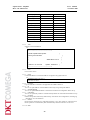
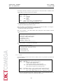
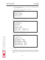
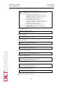
1U-Shelf Optical Amplifier User’s Manual (Erbium Doped Fiber Amplifier) Optical Fiber Amplifier Rev.1.2 1U-Shelf Series User’s Manual November 2007 Contents INTRODUCTION................................................................................ 5 1 1.1 About this Manual ..................................................................................................................5 1.2 General Descriptions ..............................................................................................................5 1.3 Mechanical Dimensions and Operational Conditions .........................................................5 1.4 Precautions for Installation and Warnings...........................................................................5 1.5 Grounding Considerations.....................................................................................................6 1.6 Laser Safety.............................................................................................................................6 PREPARATION................................................................................... 7 2 2.1 Summary .................................................................................................................................7 2.2 Check the Contents.................................................................................................................7 2.3 How to Connect the Power Supply........................................................................................7 2.4 How to connect the optical cable ...........................................................................................8 DESCRIPTION.................................................................................... 9 3 3.1 Summary .................................................................................................................................9 3.2 Panel Description ....................................................................................................................9 3.2.1 Front Panel.................................................................................................................9 3.2.2 LED State Information............................................................................................10 3.2.3 Rear Panel ................................................................................................................ 11 OPERATION ..................................................................................... 12 4 4.1 Summary ...............................................................................................................................12 4.2 LCD Operation .....................................................................................................................13 4.2.1 Menu Selects ............................................................................................................13 4.2.2 Provision menu ........................................................................................................14 4.2.3 Control......................................................................................................................15 4.2.4 Status ........................................................................................................................17 4.2.5 Test............................................................................................................................19 4.2.6 Function Setting.......................................................................................................19 INTERFACE...................................................................................... 21 5 5.1 Command Line Interface (CLI) ..........................................................................................21 5.1.1 Commands ...............................................................................................................21 5.1.2 Network Configuration ...........................................................................................26 5.1.3 SNMP Configuration...............................................................................................26 5.2 SNMP MIB Table..................................................................................................................27 5.2.1 networkGrp..............................................................................................................27 5.2.2 snmpGrp ..................................................................................................................27 5.2.3 logGrp.......................................................................................................................28 5.2.4 Mpu MIB Tables......................................................................................................28 5.2.5 ofau MIB Tables.......................................................................................................29 5.2.6 Trap ..........................................................................................................................33 PERFORMANCE CHECK ................................................................ 35 6 6.1 Precautions for Testing .........................................................................................................35 2 Optical Fiber Amplifier Rev.1.2 1U-Shelf Series User’s Manual November 2007 6.2 Power Supply ........................................................................................................................35 6.3 Primary Test..........................................................................................................................35 6.3.1 Required Measuring Instruments ..........................................................................35 6.3.2 Performance Test.....................................................................................................35 6.4 Alarm Test .............................................................................................................................36 MAINTENANCE ............................................................................... 38 7 7.1 Maintenance Cautions..........................................................................................................38 7.2 Trouble Shooting Procedures...............................................................................................38 7.3 Repair Procedure ..................................................................................................................39 3 Optical Fiber Amplifier Rev.1.2 1U-Shelf Series User’s Manual November 2007 Figure Contents Figure 1. Electric Power Supply Connection ..............................................................................................7 Figure 2. Front Panel ...............................................................................................................................9 Figure 3. Rear Panel .............................................................................................................................. 11 Figure 4. Shelf Type EDFA Measuring Instrument Setup...........................................................................36 Table Contents Table 1. The Inventory of Shelf Type EDFA...............................................................................................7 Table 2. Laser On/OFF Key Switch...........................................................................................................9 Table 3. Control Switch ...........................................................................................................................9 Table 4. LED State ................................................................................................................................10 Table 5. Provision Menu Descriptions .....................................................................................................15 Table 6. Alarm Descriptions ...................................................................................................................18 Table 7 The Instrument for measuring the performance .............................................................................35 Table 8 In the cases alarm events and Alarm LEDs signs...........................................................................38 4 Optical Fiber Amplifier Rev.1.2 1U-Shelf Series 1 User’s Manual November 2007 INTRODUCTION 1.1 About this Manual This manual is the Shelf Type EDFA of DKTCOMEGA A/S. This manual consists of six sections. They are; Introduction of the Shelf Type EDFA, System Requirements, Installation, Operation, Testing, and Trouble Shooting. A brief chapter outline of this manual is below. Chapter 1, The introduction of the Shelf Type EDFA and safety cautions for proper installation. Chapter 2, How to install the Shelf Type EDFA. Chapter 3, Panel description. Chapter 4, Utilizing the LCD and Menu switch operation. Chapter 5, Interface. Chapter 6, EDFA Performance check method. Chapter 7, Maintenance and repair. 1.2 General Descriptions The Shelf Type EDFA operates in the range of 1550 nm wavelength. The Pump Laser Diode is used as an Erbium Doped Fiber pumping energy source for the EDFA. For better system performance isolators are installed on the input and output of the EDFA’s optical terminals. For convenient operation, SNMP, LED indicators, LCD, and Menu functions are assisted. The Shelf Type EDFA is available in a variety of electrical power options such as AC (110V ~ 220V), DC (-48V). 1.3 Mechanical Dimensions and Operational Conditions DKTCOMEGA’s Shelf Type EDFA is installable in a 19” 1U Shelf. The size is 432(W) × 304(D) × 44(H) mm. The storage temperature must be kept between -40°C to 85°C. The relative humidity range is 10~95%. The operating temperature range is between 0°C to 50°C. The LCD Backlight is assurance between -10°C to 60°C. The electrical power consumption depends on the applied use of the EDFA. For more information about electrical power consumption read the TEST REPORT. 1.4 Precautions for Installation and Warnings The user must ensure there is air flow and convection through the upper and lower panels. The Shelf Type EDFA has its own internal circuitry plus an internal electrical voltage converter. Both generate heat. Unrestricted air flow is required for proper operating conditions. The optical adapters for the EDFA input and output are located on the front panel of the Shelf Type EDFA. When received from the factory the optical adapters have a cap on them for safety and protection. Until the Shelf is installed you need to leave the caps on. The operator/user must keep the surface of the optical connecter clean. If the surface of the optical connecter is contaminated with dirt or obstructions the surface of the optical connecter may be damaged as soon as the Laser is turned on. 5 Optical Fiber Amplifier Rev.1.2 1U-Shelf Series 1.5 User’s Manual November 2007 Grounding Considerations The Shelf Type EDFA includes Laser Diodes and Photo Diodes those are extremely sensitive to electrical static. You must always handle the EDFA with extra care. When you unpack or install the EDFA you must obey all the ESD (electro static discharge) precautions as well as work with a grounded wrist strap. Therefore, proper ESD precautions are always recommended. To avoid performance degradation or loss of functionality, install in a properly grounded working shelf. The F.G. terminal must be connected to Earth Ground for protection of the unit during installation and operation. To protect the installation and to prevent unexpected accidents, such as lightning, static electricity, short circuit, surges, etc..., you must use a grounded receptacle for the AC power cord. 1.6 Laser Safety FDA/CDRH Class IIIb and IEC® 60825 Class 3B laser product. All versions are Class 3B laser products per IEC 60825-1:1993. CAUTION : Use of controls, adjustment, and procedures other than those specified herein may result in hazardous laser radiation exposure. B 6 Optical Fiber Amplifier Rev.1.2 1U-Shelf Series 2 User’s Manual November 2007 PREPARATION 2.1 Summary In this chapter, the first steps of installation after unpacking are covered. inventory, basic electrical and optical connections are presented. 2.2 The box Check the Contents After unpacking you need to check the contents. The inventory should be as follows: Table 1. The Inventory of Shelf Type EDFA Item Quantity Shelf Type EDFA Shelf 1 Instructions manual 1 book TEST REPORT 1 booklet Remarks Including EDFA Inspect the outside of the EDFA. WARNING: Remember to take all proper grounding precautions. 2.3 How to Connect the Power Supply Figure 1 shows the electrical connectors with the input power terminals on the front panel of the Shelf Type EDFA. The user must select the applicable power connections for their application and properly connect to the input power terminal. Figure 1. Electric Power Supply Connection AC input voltage range: 85~265 VAC, 47~440 Hz DC input voltage range: -36~-72V(for DC-48V) Total power consumption: Refer to the TEST REPORT. AC Power Supply: There is a fuse in the AC power socket. After connecting the AC power cord to the unit, turn on the power switch on the front panel. If the green LED on the power switch turns on, the system electric power supply is normal (OK). If the green LED does not come on, you need to check the power-in cord and then the AC power fuse. DC Power supply: When you connect DC power supply, handle it very carefully. Make sure you connect the positive (+) and negative (-) connections properly, positive supply to the positive input and negative supply to the negative input. If damage is caused by the user due to improper connections and the product does not work properly or malfunctions, 7 Optical Fiber Amplifier Rev.1.2 1U-Shelf Series User’s Manual November 2007 DKTCOMEGA is not liable for repairs or replacement of the unit. If the green LED on the power switch turns on, the system electric power supply is normal (OK). 2.4 How to connect the optical cable The Shelf Type EDFA supports various optical connectors. According to the users requirements connect the optical cable to the input and the output optical adapters on the front panel of the Shelf Type EDFA. 8 Optical Fiber Amplifier Rev.1.2 1U-Shelf Series 3 User’s Manual November 2007 DESCRIPTION 3.1 Summary In this chapter, general information about the front and rear panels of the Shelf type EDFA are explained. The individual switches and connections will be introduced. 3.2 Panel Description 3.2.1 Front Panel Figure 2 shows the front panel of the Shelf Type EDFA. The components are: AC power inlet (optional a DC power terminal), a power switch with a power LED included, an LCD capable of 2×20 letters for reading the menu states, 4 menu control switches for selecting the LCD menus, a Laser ON/OFF key switch, an EDFA state indicating LED and optical adapter cassette. (a) Front Panel with AC Power inlet (Number of output port.: 1 to 8 ports) (b) Front Panel with DC Power terminal (Number of output port.: 1 to 8 ports) Figure 2. Front Panel Laser On/Off Key Switch Table 2. Laser On/OFF Key Switch Conditions Performance ON Operate EDFA normally OFF Forcefully turn off the EDFA output power Control Switch Table 3. Control Switch Switch Performance MENU Enter the menu or move the previous menu ENTER Apply the current menu UP/DOWN Move the menu items 9 Optical Fiber Amplifier Rev.1.2 1U-Shelf Series User’s Manual November 2007 LED state on the front panel Table 4. LED State Condition Name Color Power Supply POWER Green Power Supply indicator ACT Green Indicates EDFA install state and operation state LOS Red Indicates optical signal input state of the EDFA LOP Red Indicates optical signal output state of the EDFA BIAS Yellow Indicates Pump Laser Diode BIAS Alarm TEMP Yellow Indicates Pump Laser Diode Temperature Alarm EDFA 3.2.2 Performance LED State Information POWER LED When an electric power is applied to the EDFA and the power switch is turned on, the POWER LED in the power switch turns on. ACT LED When the EDFA is properly installed, the ACT LED turns on. However, if the Provision Menu is selected the DEACT state, the ACT LED turns off. LOS (Loss of Signal) LED When the input optical signal power to the EDFA is lower than the minimum input conditions, the LOS LED turns on (see the TEST REPORT). The threshold for triggering the loss of input signal alarm is set below the minimum optical input level. Commonly 3dB below the minimum input power level is set as the threshold. If the LOS alarm is activated the EDFA automatically changes to the Laser Shutdown state, the output power is turned off, and the LOP LED turns on. In response to a loss of input signal, the bias current of the pump laser diode goes into a shutdown state to prevent the development of dangerous laser diode operation conditions. If laser shutdown does not occur, the pump laser diode can be damaged. This condition is automatically reset when the input power is restored to a power above the alarm threshold for the EDFA. The EDFA returns to its normal state, the LOS LED turns off, and the Laser ON state condition returns. If the output power of the EDFA is normal, the LOP LED turns off. LOP(Loss of Output Power) LED When the optical output power of the EDFA is lower than the reference power, the LOP LED turns on. (see the TEST REPORT) This level is commonly 3dB below the reference output power. If the Laser OFF state is selected from the LCD menu, the LOP LED turns on. The LOP alarm turns off when the output optical power of the EDFA is normal. BIAS LED The Pump Laser Diode provides pumping energy to the Erbium Doped Fiber in the EDFA. The pumping power of the Pump Laser Diode is controlled by applying a bias current. If the bias current of the pump laser diode is loaded above 95% of the end-of-life (EOL) value, the pump bias current alarm is activated. The EOL bias current is defined as 120% of the beginning-of-life (BOL) bias current. The pump laser diode driver is limited to never exceed the EOL bias level. This is an indicating LED for an over current condition of the Pump Laser Diode bias current. 10 Optical Fiber Amplifier Rev.1.2 1U-Shelf Series User’s Manual November 2007 If the BIAS alarm is activated the EDFA changes automatically to the Laser Shutdown state, the EDFA output power is turned off, and the LOP LED turns on. TEMP LED The internal temperature of the Pump Laser Diode must be kept constant. If the internal temperature of the Pump Laser Diode goes outside of the operational range, the TEMP LED is activated. If the TEMP alarm signal is activated the EDFA automatically changes to the Laser Shutdown state and the LOP LED is activated. 3.2.3 Rear Panel The rear panel of the Shelf Type EDFA only consists of fan. Figure 3. Rear Panel 11 Optical Fiber Amplifier Rev.1.2 1U-Shelf Series 4 User’s Manual November 2007 OPERATION 4.1 Summary In this chapter, the operation of the EDFA using the LCD menu will be explained. The diagram below shows the operational menu tree selectable. MAIN MENU SUB MENU Menu Provision EDFA Act EDFA Deact Laser Key Switch is “ON” Control LASER Laser ON Laser OFF Buzzer Buzzer ON Buzzer OFF Status Input Power Output Power LD Bias LD Thermistor Case Temperature Alarm EDFA Model Test LED, Buzzer Function Setting Time 12 Optical Fiber Amplifier Rev.1.2 1U-Shelf Series 4.2 User’s Manual November 2007 LCD Operation The functions of the Shelf Type EDFA are supported by selecting the LCD Menu switch on the front panel. If an electric power is applied, the initial display of the LCD display is as follows. Optical Amplifier Company Name WARNING: In all LCD menus if you do not select a menu switch for about 15 seconds, the menu automatically returns to the previous menu state. 4.2.1 Menu Selects The main menu is Provision, Control, Status, Test, Function Setting. menu by the Menu switch. You can select any The procedure of selection in the MAIN MENU is as follows: Push the Menu switch on the start screen. The LCD display is changed to the next screen and then the cursor is on the “Provision” menu. > Provision Control If you push the Down switch, the cursor moves to the “Control” menu. > Provision Control With the cursor placed on the menu “Control”, if you push the Down switch, the LCD screen changes and the cursor moves to the next menu, “Status”. > Status Test With the cursor on the menu “Status,” push the Down switch, the cursor moves to the “Test” menu. > Status Test From the above screen push the Down switch. The cursor moves to the “Function Setting” menu, changing the LCD screen. > Function Setting Provision In this condition MAIN MENU is finished. 13 Optical Fiber Amplifier Rev.1.2 1U-Shelf Series User’s Manual November 2007 From the above screen if you push the Down switch, the start MAIN MENU screen is returned. > 4.2.2 Provision Control Provision menu User is able to control the operational state of the EDFA in the Provision menu. It is the menu for selecting active (ACT) and deactive (DEACT) operational states of the EDFA. Provision menu LCD display is changed to the next screen and then the cursor is on the “Provision” menu. > Provision Control From the cursor on the “Provision” if you push the Enter switch, the cursor moves from the Provision Menu to the SUB MENU. EDFA Setting ACT ACT The first line of the above screen indicates the current state of the EDFA. The initial state of the Provision menu depends on the setting state. If you want to change the current state, move the cursor by the Up or Down switch to the menu you wish to select. From the current state move the cursor by Up or Down switch to the position on the “DEACT” menu. EDFA Setting ACT DEACT Push the Enter switch. The LCD screen displays the operation selected above is complete. Set & Store EDFA : DEACT If you push Enter or Menu switch, the cursor moves to the “DEACT” menu. And if you do not select a menu switch for about 15 seconds, the menu automatically returns to the previous state and display. After selecting the desired state, if you want to move to the MAIN MENU above on the screen you can change the menu with the Menu switch. 14 Optical Fiber Amplifier Rev.1.2 1U-Shelf Series User’s Manual November 2007 Provision State Descriptions Within the Provision menu the start state is the ACT (Active) state when the power is turned on. If you select the DEACT state at the Provision Menu, the EDFA is working an normal operation except the alarm information. The table shows the operational state of the EDFA at the Provision menu. Table 5. Provision Menu Descriptions ACT State DEACT State EDFA: normal operation Status LED: OFF (Alarm information is not detected) EDFA: normal operation 4.2.3 Control In the Control Menu, the optical output power of the EDFA can be controlled by Laser ON or Laser OFF. Also you can select the Buzzer sound in the Buzzer Control menu. From the MAIN MENU using the Menu switch move the cursor to the “Control”. > Provision Control If you push Enter switch, the cursor moves to the “LASER” menu. Laser ON > LASER BUZZER From the below screen the first line indicates the current selected laser state of the EDFA. If you want to select a different state from your current laser state, using the Up or Down switch, move the cursor to the menu that contains the state you wish to select. Laser Setting Off On To activate the output of the EDFA normally, put the cursor on the LASER ON position. Push the ENTER Switch (Laser Key switch is ON state). Set & Store Laser : On 15 Optical Fiber Amplifier Rev.1.2 1U-Shelf Series User’s Manual November 2007 If the Laser Key switch is OFF state, Laser On/Off is not changed, it remains the same state. Key switch Check Please.. Push Enter or Menu switch. If you want to turn off the output of the EDFA, push the Enter switch to move the cursor to the “OFF” position. Laser Setting Off Off In this state push the ENTER switch. Set & Store Laser : Off Note: When the Laser is selected the “Off”, the output of the EDFA also turns off and the Laser LED turns off. Buzzer ON If an alarm has occurred on the EDFA, Buzzer sound is activated. You will hear a beeping sound. As soon as the alarm condition of the EDFA is removed, the Buzzer sound automatically stops. > LASER BUZZER From the below screen the first line indicates the current selected buzzer state of the EDFA. If you want to select a state different from your current buzzer state, using the Up or Down switch, move the cursor to the menu that contains the state you wish to select. BUZZER Setting Off On Push the ENTER switch Set & Store BUZZER : ON 16 Optical Fiber Amplifier Rev.1.2 1U-Shelf Series User’s Manual November 2007 If you want to turn off the buzzer, push the Enter switch to move the cursor to the “OFF” position. Buzzer Setting Off Off In this state push the ENTER switch. Set & Store Buzzer : Off When the Buzzer OFF is selected and the EDFA alarm is occurred, the Buzzer sound is not activated. 4.2.4 Status In the Status menu you are able to monitor the operational state of the EDFA. > Status Test If you push the Enter switch, the cursor moves to the “Input Power” menu. The Input Power is the optical input power. > Input Power Output Power Input Power is displayed. Input Power +XX.XX dBm The Output Power is the EDFA output power monitoring. Input Power > Output Power The LD Bias Current is the bias current of the pump laser diode. > LD Bias Current LD Thermistor The unit of LD Bias Current is [mA]. LD Bias Current LD1 : XXXX mA LD Bias Current LDx : XXXX mA 17 The x of LDx is the number of used laser diode. Optical Fiber Amplifier Rev.1.2 1U-Shelf Series User’s Manual November 2007 The LD Thermistor is the pump laser diode temperature. The unit is centigrade [℃]. > LD Bias Current LD Thermistor LD Thermistor LD1 : XX ℃ LD Thermistor LDx : XX ℃ The Temperature is the EDFA module temperature. The unit is centigrade [℃]. > Temperature Alarm Status Temperature XX ℃ Using the Alarm menu you are able to check the EDFA Alarms. > Temperature Alarm Status To move another alarm state, push Up/Down switch. IPM : OK OPM : OK OPM : OK BIAS : FAIL Table 6. Alarm Descriptions Name Variable Descriptions IPM THER Input Power Monitor Output Power Monitor Current Thermistor TEMP Case Shows the input optical signal power of the EDFA. OK: Normal, FAIL: Abnormal Shows the output optical power of the EDFA. OK: Normal, FAIL: Abnormal Shows the state of the Pump Laser Diode Bias current. OK: Normal, FAIL: Abnormal Shows the temperature state of the Pump Laser Diode. OK: Normal, FAIL: Abnormal Shows the temperature state of the EDFA module.. OPM BIAS 18 Optical Fiber Amplifier Rev.1.2 1U-Shelf Series User’s Manual November 2007 Temperature OK: Normal, FAIL: Abnormal EDFA Model Name is the EDFA model name of built in the Shelf. > EDFA Model Name Input Power 4.2.5 Test From the Test menu you are able to test the LED, Buzzer. > Status Test If you push the Enter switch, the cursor moves to the “LED Test” menu. Test menu the operating state of all the LEDs can be checked. > In the LED LED Test Buzzer Test If you push the Down switch, the cursor moves to the “Buzzer Test” menu. Then if you push the Down switch, the operating state of the Buzzer can be checked. > 4.2.6 LED Test Buzzer Test Function Setting The Function Setting menu is Time. > Time The timer setting procedure for the internal timer is as follows: > Current Time Setting Time In the below screen the Current Time indicates the present date and time. YY YY MM DD HH MM SS 2004 06 09 15 05 30 In the Setting Time Menu, you can change the date and time to the values you need. Using the Up/Down, Enter switch move the cursor to the position that you want to change. Current Time > Setting Time If you push the Down switch, the cursor moves to another position. And Up switch change the time value 19 Optical Fiber Amplifier Rev.1.2 1U-Shelf Series User’s Manual November 2007 YYYY MM DD HH MM SS 2004 06 09 15 05 30 YYYY MM DD HH MM SS 2005 06 09 15 05 30 If you push the Enter switch, the time value is stored. 20 Optical Fiber Amplifier Rev.1.2 1U-Shelf Series 5 User’s Manual November 2007 INTERFACE 5.1 Command Line Interface (CLI) User can monitor or control EDFA through Ethernet port or COM port. ADMIN and USER accounts are established separately for different access priorities. ADMIN account holder can set passwords for both ADMIN and USER accounts. In addition, the task of administrative work, such as network connection, monitor and control of EDFA are to be performed under ADMIN account. USER account holder, usually equipment operator, is allowed to monitor EDFA’s current status. 5.1.1 Commands Information on how to set arguments of each Command is provided after a Command followed by Enter key. ? : Show available Commands in CLI with description for user’s reference. ver: Display basic hardware information on EDFA. cls: Clear the console screen. ping: Check connection of equipment to which an IP address is assigned. logout : Log out from ADMIN or USER account. Not available for Telnet connection. ip: IP address. Key information for Telnet, SNMP, or TCP/IP connection. subnetmask: Subnetmask address. Key information for Telnet, SNMP, or TCP/IP connection. gateway: Gateway address. Key information for Telnet, SNMP, or TCP/IP connection. initsys: reset: Reset to factory default setup. Reset the network connection due to network reconfiguration or any other network connection problems. Operation of optical amplifier is not affected by this command. mpu : Main Process Unit configuration as well as setup view and confirmation. ofau : OFAU (Optical Fiber Amplifier Unit, amplifier module in side shelf-type EDFA or amplifier module card for rack-type EDFA) configuration as well as setup view and confirmation. snmp : SNMP configuration as well as setup view and confirmation. log : Check log information and eliminate log. Log information can only be eliminated through console. timesync : Manually update RTC (Real Time Clock). Command Execution Privilege command ADMIN USER ver O O cls O O 21 Optical Fiber Amplifier Rev.1.2 1U-Shelf Series User’s Manual November 2007 ping O O logout O O ip Read/Write Read Only subnetmask Read/Write Read Only gateway Read/Write Read Only initsys O X reset O O mpu Read/Write Read Only otu Read/Write Read Only ofau Read/Write Read Only snmp Read/Write Read Only log Read/Write Read Only timesync O X 5.1.1.1 VER Software version information. ex) [ADMIN]# VER +-------------------------------------------------+ | Otical Amplifier Shelf System | | Debug Console Mode | | | | SNMP Board ver 1.0 | | | | S/W Ver : 01.00.00.00 Update : 2006/12/11 | +-------------------------------------------------+ 5.1.1.2 CLS Clear console screen. 5.1.1.3 PING Confirm IP address to see if the IP address is assigned to any physical device. ex) [ADMIN]# PING 192.168.0.1 192.168.0.1 is alive. 5.1.1.4 LOGOUT Log out from RS-232 interface. Not applicable for SNMP connection. 5.1.1.5 IP View or set up IP Address. Avoid IP address collision by using a unique IP address. 5.1.1.6 SUBNETMASK View or set up SubnetMask Address. Check network connection configuration before set up. 5.1.1.7 GATEWAY View or set up Gateway Address. Confirm Gateway address of connected network before set up. 5.1.1.8 INITSYS Initialize the product with factory default setup. Note that all the configurations, including log information, are to be initialized. 5.1.1.9 RESET Reset network connections for configuration change or any other needs for connection reset. OFAU operation is not affected by this command. Only network connection is to be reset. 5.1.1.10 MPU 22 Optical Fiber Amplifier Rev.1.2 1U-Shelf Series User’s Manual November 2007 Check MPU information and status of physical devices connected the MPU. In addition, basic set up of MPU is possible. See below for examples. ex) Usage : MPU [ARG1] [ARG2] [ARG3] ARG1 : GET, SET ARG2 : GET - SYSINFO STATUS SET - TIME DESCR ARG3 : TIME - Set New Time. [YYYYMMDDhhmmss] DESCR - Enter User define string.[Len:0 ~ 20] MPU SET DESCR [Len : 0 ~20]: Input MPU Description ex) MPU SET DESCR Shelf-OFA for Node 1 MPU SET TIME [YYYYMMDDhhmmss] : Input time information for MPU. Use 14 digits to input the time information, such as [YYYYMMDDhhmmss]. ex) MPU SET TIME 20061207091830 MPU GET SYSINFO : View MPU Model Name, Description, Serial Number, Firmware Version, Hardware Version. ex) [ADMIN]# MPU GET SYSINFO -------------------------------------------------Model Name : EDFA-21-220-SA-04 Description : DKTCOMEGA EDFA Serial Number : 0000 Firmware Version : 1.00 Hardware Version : 1.00 -------------------------------------------------MPU GET_STATUS : View MPU time information. ex) [ADMIN]# MPU GET STATUS -------------------------------------------------Current Time (Bit) : 2006/12/07 11:48:34 Provision (Bit) : 0x1 Card ACT (Bit) : 0x1 Card Alarm (Bit) : 0x0 -------------------------------------------------5.1.1.11 OFAU Check information on OFAU and its status. In addition, basic set up of OFAU is possible. See below for examples. ex) Usage : OFAU [ARG1] [ARG2] [ARG3] [ARG4] ARG1 : GET, SET ARG2 : GET - SYSINFO. OFAU Model Information. STATUS. OFAU Module Status. CONFIG. OFAU Module Configuration Data. SET - AOL. Alarm Of Loss Input Power. (Rack type only) REF. Reference Output Power. (Rack type only) ARG3 ARG4 : Slot Number Value. [1 ~ 10]. (if absent, monitor whole OFAU slot) : SET - AOL. Unit[0.1 dBm] (Input Power Min ~ Input Power Max) REF. Unit[0.1 dBm] (Output Power Min ~ Output Power Max) OFAU SET AOL [Input Power Min ~ Input Power Max] : Define threshold input power value for Alarm Of Loss Input Power (Rack type EDFAs only) 23 Optical Fiber Amplifier Rev.1.2 1U-Shelf Series User’s Manual November 2007 OFAU SET REF [Output Power Min ~ Output Power Max] : Define Reference Output Power (Rack type EDFAs only) OFAU GET SYSINFO – View OFAU module basic Information ex) [ADMIN]# OFAU GET SYSINFO -------------------------------------------------OFAU Slot Number [0] Model Name : 21-220-SA-04 Description : DKTCOMEGA Serial Number : 200604130001 Firmware Version : 1.00 Hardware Version : 1.00 -------------------------------------------------OFAU GET STATUS – View OFAU current status. ex) [ADMIN]# OFAU GET STATUS -------------------------------------------------OFAU Slot Number [0] EDFA Alarm Status (Bit) : 0x0 Operation Mode : 30 Case Temp. : 43 ['C] +5V : 5.0 [V] Input Power : 0.7 [dBm] Output Power : 14.8 [dBm] Laser Alarm Status (Bit) : 0 LD[1] Bias : 180 [mA] LD[1] Temp. : 25 ['C] LD[2] Bias : 217 [mA] LD[2] Temp. : 25 ['C] LD[3] Bias : 408 [mA] LD[3] Temp. : 25 ['C] -------------------------------------------------OFAU GET CONFIG – View OFAU configuration. ex) [ADMIN]# OFAU GET CONFIG -------------------------------------------------OFAU Slot Number [0] +5V Low Limit : 4.7 [V] +5V High Limit : 5.3 [V] Input Power Minimum : -16.2 [dBm] Input Power Maximum : 7.1 [dBm] Output Power Minimum : -3.9 [dBm] Output Power Maximum : 19.0 [dBm] Alarm Of Loss Power Limit : 0.0 [dBm] Reference Output Power Limit : 14.8 [dBm] LD[1] Bias Current Maximum : 415 [mA] LD[2] Bias Current Maximum : 661 [mA] LD[3] Bias Current Maximum : 1000 [mA] -------------------------------------------------5.1.1.12 SNMP Before SNMP interface connection, a few preliminary setups need to be done. SNMP interface requires Read Only Community and Read Write Community to be set up. For Trap set up, Trap IP, Trap Community, and Trap Enable/Disable need to be defined beforehand. See below for examples. 24 Optical Fiber Amplifier Rev.1.2 1U-Shelf Series User’s Manual November 2007 ex) Usage : SNMP [ARG0] [ARG1] [ARG2] [ARG3] ARG0 : TRAP , ROCOMM, RWCOMM, TRAPEN, TRAPCOMM ARG1 : GET , SET ARG2 : GET - TRAP : Trap Receiver Index. (0 ~ 4) - ROCOMM : Read Only Community. Max StrLen 10 - RWCOMM : Read Write Community. Max StrLen 10 - TRAPEN : Trap Receiver Index. (0 ~ 4) - TRAPCOMM : Trap Receiver Index. (0 ~ 4) SET - TRAP : Trap Receiver Index. (0 ~ 4) - ROCOMM : Read Only Community. Max StrLen 10 - RWCOMM : Read Write Community. Max StrLen 10 - TRAPEN : Trap Receiver Index. (0 ~ 4) - TRAPCOMM : Trap Receiver Index. (0 ~ 4) ARG3 : SET - TRAP : Manager IP. [XXX.XXX.XXX.XXX] - TRAPEN : ON, OFF - TRAPCOMM : Community Public. Max StrLen 10 SNMP GET TRAP [Index] ex) [ADMIN]# SNMP GET TRAP 1 SNMP Trap Receiver[1] IP : 192.168.0.52 SNMP GET ROCOMM ex) [ADMIN]# SNMP GET ROCOMM SNMP Read Only Community : public SNMP GET RWCOMM ex) [ADMIN]# SNMP GET RWCOMM SNMP Read Write Community : PRIVATE SNMP GET TRAPEN [Index] ex) [ADMIN]# SNMP GET TRAPEN 1 SNMP Trap Receiver-[1] State : OFF[0] SNMP GET TRAPCOMM [Index] ex) [ADMIN]# SNMP GET TRAPCOMM 1 SNMP Trap Receiver-[1] Trap Community : public SNMP SET ROCOMM [string] ex) [ADMIN]# SNMP SET ROCOMM PUBLIC SNMP Community public : PUBLIC setting success. This setting will be applied after reboot. SNMP SET RWCOMM [string] ex) [ADMIN]# SNMP SET RWCOMM PUBLIC SNMP Community public : PRIVATE setting success. This setting will be applied after reboot. SNMP SET TRAPEN [Index] [ON/OFF] ex) [ADMIN]# SNMP SET TRAPEN 1 ON SNMP Trap[1] Enable Setting Successful... SNMP SET TRAPCOMM [Index] [string] ex) 25 Optical Fiber Amplifier Rev.1.2 1U-Shelf Series User’s Manual November 2007 [ADMIN]# SNMP SET TRAPCOMM 1 public SNMP Trap Receiver[1] Trap Community : public setting success. This setting will be applied after reboot. 5.1.2 Network Configuration User needs to set up network configuration for the product. Factory default IP address is 192.168.0.100. Network configuration is to be modified by either SNMP or Telnet. The modified configuration is enacted by reboot. The reset command of CLI also allows the modified configuration to be enacted. If information on modified configuration is forgotten, then use the console to check or reset IP address. Note that network configuration can be set only by ADMIN account. Factory Default 5.1.3 Item Default Value IP 192.168.0.100 SubnetMask 255.255.255.0 Gateway 192.168.0.1 SNMP Configuration This unit supports SNMPv1, SNMPv2, and SNMPv2c. SNMPv3 will not be supported until next software upgrades. Using MIB Table for SNMP interface, GUI (Graphic User Interface) can be established for remote control and monitoring. Read Only Community: Accounts for general users like operators who are not allowed to modify configurations. Identical to USER account in CLI. Read/Write Community: Accounts for system administrators, who can modify product configurations. Identical to ADMIN in CLI Trap IP: IP address for Trap Receiver which receives alarm information in an event of alarm activation. Up to 5 Trap IP can be assigned. Trap Enable: Enable alarm transmission to Trap IP. Assign Trap IP before Trap Enable Trap Community: The community name to be used by the device when sending traps. Factory Default Item sub-command Default Value RO community ROCOMM PUBLIC RW community RWCOMM PRIVATE Trap IP TRAP 0.0.0.0 Trap Enable TRAPEN OFF 26 Optical Fiber Amplifier Rev.1.2 1U-Shelf Series 5.2 User’s Manual November 2007 SNMP MIB Table 5.2.1 networkGrp DKTCOMEGA System MIB : 1.3.6.1.4.1.25454.1 Name OID Type Access Factory Default networkIpAddr 2.1 networkSubnetAddr 2.2 IpAddress R/W 192.168.0.100 IpAddress R/W 255.255.255.0 networkGWYAddr 2.3 IpAddress - networkIpAddr : Network IP address R/W 192.168.0.1 - networkSubnetAddr : Subnet Mask Address - networkGWYAddr : Gateway Address 5.2.2 snmpGrp DKTCOMEGA System MIB : 1.3.6.4.1.25454.1 Access Factory Default 1 Name OID Type snmpVer 3.1 Integer32 R/W snmpRoComm 3.2 DisplayString R/W PUBLIC snmpRwComm 3.3 DisplayString WO PRIVATE snmpAdminAuthType 3.4 Integer32 R/W 0 snmpUserAuthType 3.5 R/W 0 snmpTrapMgmtTable 3.8 snmpTrapMgmtEntry 3.8.1.1 Integer32 SEQUENCE OF SnmpTrapMgmtEntry SnmpTrapMgmtEntry --- snmpTrapIndex 3.8.1.1.1 Integer32 RO -- snmpTrapIp 3.8.1.1.2 IpAddress R/W -- snmpTrapComm 3.8.1.1.3 DisplayString R/W -- snmpTrapEnable 3.8.1.1.4 Integer32 R/W -- - snmpVer : SNMP version. 0 : no action 1 : SNMPv1, SNMPv2 2 : SNMPv3 3 : SNMPv1, SNMPv2, SNMPv3 - snmpRoComm: Community for Read Only in SNMPv1, SNMPv2, SNMPv2. - snmpRwComm: Community for Read and Write in SNMPv1, SNMPv2, SNMPv2. - snmpAdminAuthType: Determine SNMPv3 protocol (MD5 or SHA1) by ADMIN. (Not available until SNMPv3 is supported) 0 : none 1 : MD5 2 : SHA1 - snmpUserAuthType: Determine SNMPv3 protocol (MD5 or SHA1) by USER. (Not available until SNMPv3 is supported) 0 : none 1 : MD5 2 : SHA1 27 Optical Fiber Amplifier Rev.1.2 1U-Shelf Series User’s Manual November 2007 - snmpTrapMgmtTable : Table for SNMP Trap management - snmpTrapMgmtEntry : List for SNMP Trap management - snmpTrapIndex : Trap Row Data index - snmpTrapIp : Set up IP address for Trap Receiver. 0.0.0.0 will remove IP address and disable Trap Receiver feature. - snmpTrapComm : Specify SNMP trap community information. - snmpTrapEnable : Enable or disable SNMP Trap. 5.2.3 logGrp DKTCOMEGA System MIB : 1.3.6.4.1.25454.1 Name OID logTable 4.1 logEntry 4.1.1 Type SEQUENCE OF LogEntry LogEntry logIndex 4.1.1.1 Integer32 RO logDate 4.1.1.2 DisplayString RO logData 4.1.1.3 DisplayString RO logType 4.1.1.4 Integer32 RO 비 고 Access logDescr 4.1.1.5 DisplayString - logTable: Table for system log management RO - logEntry: List of system log. - logIndex : Log Index up to 200 events. The oldest log stored at the top. - logDate : Time info for log in a format of YYYY/MM/DD hh:mm:ss. - logData : Data information for log. - logType : Type of log. logType Type Description 0 System Log for system status 1 Device Log for device status change 2 Alarm Log for alarm occurrence - logDescr : Log description. 5.2.4 Mpu MIB Tables DKTCOMEGA Product MIB : 1.3.6.4.1.25454.51.1 Name OID Type Access mpuModelName 1.1 DisplayString RO mpuDescr 1.2 DisplayString R/W mpuSerialNumber 1.3 DisplayString RO mpuFWRev 1.4 DisplayString RO mpuHWRev 1.5 DisplayString RO mpuSysUpTime 1.6 DisplayString R/W mpuVoltLowSet 2.1 Integer32 RO mpuVoltHighSet 2.2 Integer32 RO mpuVoltValue 3.1 Integer32 RO mpuVccLowAlarm 3.2 Integer32 RO 28 Optical Fiber Amplifier Rev.1.2 1U-Shelf Series User’s Manual November 2007 mpuVccHighAlarm 3.3 mpuCardStatusEntry 3.4.1 Integer32 SEQUENCE OF MpuCardStatusEntry MpuCardStatusEntry mpuCardStatusTable 3.4 mpuCardIndex 3.4.1.1 Integer32 RO mpuCardIdentity 3.4.1.2 DisplayString RO mpuCardProvision 3.4.1.3 Integer32 R/W mpuCardActiveState 3.4.1.4 Integer32 RO mpuCardFailAlarm 3.4.1.5 Integer32 RO mpuCardOperStatus 3.4.1.6 Integer32 RO Integer32 R/W mpuCardAdminStatus 3.4.1.7 - mpuModelName : Model Name of MPU. RO - mpuDescr : Description of MPU that user can specify. - mpuSerialNumber : MPU Serial Number. - mpuFWRev : MPU Firmware Version. - mpuHWRev : MPU Hardware Version. - mpuSysUpTime : RTC of MPU in “YYYY/MM/DD hh:mm:ss” format. - mpuVoltLowSet : Threshold voltage for mpuVccLowAlarm in unit of 0.1V. - mpuVoltHighSet : Threshold voltage for mpuVccHighAlarm in unit of 0.1V. - mpuVoltValue : Voltage measured at MPU in unit of 0.1V. - mpuVccLowAlarm : Low voltage alarm information when mpuVoltValue is less than mpuVoltLowSet. - mpuVccHighAlarm : High voltage alarm information when mpuVoltValue is higher than mpuVoltHighSet. - mpuCardStatusTable : Table for information of circuit boards (CARD) managed by MPU. - mpuCardStatusEntry : List of CARD information - mpuCardIndex : Slot number for the CARDs. - mpuCardIdentity : CARD ID number 0 : NULL (No Cards) 1 : PSU (Power Supply Unit) 2 : OTU (Optical Transmitter Unit, not available for shelf type EDFAs) 3 : OFAU (Optical Fiber Amplifier Unit) - mpuCardProvision : CARD alarm masking information. If a particular CARD’s mpuCardProvision is set to be ‘1’, alarm information is not communicated to MPU. - mpuCardActiveState : CARD connection information. If CARD is in place, “1” is assigned. In a shelf type EDFA, it is always “1” since each CARD can not be detached from the slot. - mpuCardFailAlarm : CARD alarm information. Activated until alarm for each and every CARD inside the product is cleared. - mpuCardOperStatus : CARD operation monitoring. - mpuCardAdminStatus : CARD operation control and monitoring. 5.2.5 ofau MIB Tables DKTCOMEGA Product MIB : 1.3.6.4.1.25454.51.3 29 Optical Fiber Amplifier Rev.1.2 1U-Shelf Series User’s Manual November 2007 Name OID ofauMgmtTable 1.1 ofauConfTable 2.1 ofauEdfaStatusTable 3.1 ofauLaserStateTable 3.2 ofauAlarmTable 3.3 ofauLaserAlarmTable 3.4 Type SEQUENCE OF OfauMgmtEntry SEQUENCE OF OfauConfEntry SEQUENCE OF OfauEdfaStatusEntry SEQUENCE OF OfauLaserStateEntry SEQUENCE OF OfauAlarmEntry SEQUENCE OF OfauLaserAlarmEntry Access Note 5.2.5.1 ofauMgmtTable - ofauMgmtTable : Table for OFAU management and configuration information. Name OID ofauMgmtTable 1.1 ofauMgmtEntry 1.1.1 Type SEQUENCE OF OfauMgmtEntry OfauMgmtEntry ofauMgmtIndex 1.1.1.1 Integer32 Access Note RO ofauMgmtModelName 1.1.1.2 DisplayString RO ofauMgmtDescr 1.1.1.3 DisplayString RO ofauMgmtSerialNumber 1.1.1.4 DisplayString RO ofauMgmtFWRev 1.1.1.5 DisplayString RO ofauMgmtHWRev 1.1.1.6 DisplayString RO ofauMgmtLedTest 1.1.1.7 Integer32 R/W ofauMgmtLaserOn 1.1.1.8 Integer32 R/W ofauMgmtAlarmLossInPwr 1.1.1.9 Integer32 R/W ofauMgmtRefOutPwr 1.1.1.10 Integer32 R/W - ofauMgmtEntry : List of OFAU management information. - ofauMgmtIndex : Slot number for OFAU. In shelf type OFA, it is always ‘1’. - ofauMgmtModelName : OFAU Model Name. - ofauMgmtDescr : OFAU description. - ofauMgmtSerialNumber : OFAU Serial number. - ofauMgmtFWRev : OFAU Firmware Version. - ofauMgmtHWRev : OFAU Hardware Version - ofauMgmtLedTest : Test LED for OFAU (Rack type) or MPU (Shelf type). Value 1 Operation Switch on and off the LED five times for 1 second duration. Reset ofauMgmtLedTest value to ‘0’ after the test. - ofauMgmtLaserOn : Switch on or off pump LDs in OFAU. Value Laser Control 30 APC (Automatic Power Control), turn on and maintain LD power level. 40 ALS (Automatic Laser Shutdown), turn off LDs. 30 Optical Fiber Amplifier Rev.1.2 1U-Shelf Series User’s Manual November 2007 - ofauMgmtAlarmLossInPwr: Threshold input power level for Input Power Alarm activation, in unit of 0.1 dBm. - ofauMgmtRefOutPwr : Threshold output power level for Output Power Alarm activation, in unit of 0.1 dBm. 5.2.5.2 ofauConfTable - ofauConfTable : Table for minimum and maximum values for parameters of OFAU. Name OID ofauConfTable 2.1 ofauConfEntry 2.1.1 Type SEQUENCE OF OfauConfEntry OfauConfEntry Access ofauConfInPwrMin 2.1.1.1 Integer32 RO ofauConfInPwrMax 2.1.1.2 Integer32 RO ofauConfOutPwrMin 2.1.1.3 Integer32 RO ofauConfOutPwrMax 2.1.1.4 Integer32 RO ofauConfReflOutPwrMin 2.1.1.5 Integer32 RO ofauConfReflOutPwrMax 2.1.1.6 Integer32 RO ofauConfVccLow 2.1.1.7 Integer32 RO ofauConfVccHigh 2.1.1.8 Integer32 RO Note - ofauConfEntry : List of OFAU configuration parameters - ofauConfInPwrMin : OFAU Input Power Minimum value, in unit of 0.1 dBm. - ofauConfInPwrMax : OFAU Input Power Maximum value, in unit of 0.1 dBm. - ofauConfOutPwrMin : OFAU Output Power Minimum value, in unit of 0.1 dBm. - ofauConfOutPwrMax : OFAU Output Power Maximum value, in unit of 0.1 dBm. - ofauConfReflOutPwrMin : OFAU Reflected Output Power Minimum value, in unit of 0.1dBm. Subject to ofauEdfaStatusUnitOpt setup. - ofauConfReflOutPwrMax : OFAU Reflected Output Power Maximum value, in unit of 0.1dBm. Subject to ofauEdfaStatusUnitOpt setup. - ofauConfVccLow : OFAU Vcc Low Limit value, in unit of 0.1 V. - ofauConfVccHigh : OFAU Vcc High Limit value, in unit of 0.1 V. 5.2.5.3 ofauEdfaStatusTable - ofauEdfaStatusTable : Table for OFAU status management. Name OID ofauEdfaStatusEntry 3.1.1 Type SEQUENCE OF OfauEdfaStatusEntry OfauEdfaStatusEntry ofauEdfaStatusTable 3.1 ofauEdfaStatusUnitOpt 3.1.1.1 Integer32 RO ofauEdfaStatusAlarmStatus 3.1.1.2 Integer32 RO ofauEdfaStatusOperMode 3.1.1.3 Integer32 RO ofauEdfaStatusCaseTemp 3.1.1.4 Integer32 RO ofauEdfaStatusVcc 3.1.1.5 Integer32 RO ofauEdfaStatusInPwr 3.1.1.6 Integer32 RO 31 Access Note Optical Fiber Amplifier Rev.1.2 1U-Shelf Series User’s Manual November 2007 ofauEdfaStatusOutPwr 3.1.1.7 Integer32 RO ofauEdfaStatusReflOutPwr 3.1.1.8 Integer32 RO - ofauEdfaStatusEntry : List of OFAU status information. - ofauEdfaStatusUnitOpt : OFAU Reflected Output Power enable/disable. ofauEdfaStatusUnitOpt Value Reflected Output Power 0 Disable 1 Enable - ofauEdfaStatusAlarmStatus : OFAU alarm information. Bit Description 0 P5V Low 1 P5V High 2 Case Temperature 3 Input Power 4 Output Power 5 Reflected Output Power (Option 1) - ofauEdfaStatusOperMode : OFAU Operation Mode. Operation Mode APC Value Description 30 Automatic constant power control mode. ALS 40 Automatic laser shutdown by user. APC ALS 43 Automatic laser shutdown by APC alarm. AGC ALS 42 Key ALS 44 Automatic laser shutdown by AGC (Automatic Gain Control) alarm. Automatic laser shutdown by key switch AGC 20 Automatic constant gain control mode. - ofauEdfaStatusCaseTemp : OFAU Case Temperature, in unit of °C. - ofauEdfaStatusVcc : OFAU Vcc, in unit of 0.1 V. - ofauEdfaStatusInPwr : OFAU Input Power, in unit of 0.1 dBm. - ofauEdfaStatusOutPwr : OFAU Output Power, in unit of 0.1 dBm. - ofauEdfaStatusReflOutPwr: OFAU Reflect Output Power, in unit of 0.1dBm. Subject to ofauEdfaStatusUnitOpt setup. 5.2.5.4 ofauLaserStateTable - ofauLaserStateTable : Table for OFAU Laser (or Pump LDs) management. Name OID ofauLaserStateTable 3.2 ofauLaserStateEntry 3.2.1 Type SEQUENCE OF OfauLaserStateEntry OfauLaserStateEntry ofauLaserStateLDIndex 3.2.1.1 Integer32 RO ofauLaserStateLDBias 3.2.1.2 Integer32 RO ofauLaserStateLDTemp 3.2.1.3 Integer32 RO 32 Access Note Optical Fiber Amplifier Rev.1.2 1U-Shelf Series User’s Manual November 2007 ofauLaserStateLDBiasCurMax 3.2.1.4 Integer32 RO - ofauLaserStateEntry : List of OFAU Laser status information. - ofauLaserStateLDIndex : OFAU Laser index - ofauLaserStateLDBias : OFAU LD Bias, in unit of mA - ofauLaserStateLDTemp : OFAU LD Temperature, in unit of °C. - ofauLaserStateLDBiasCurMax : OFAU LD Bias Current Maximum, in unit of mA 5.2.5.5 ofauAlarmTable - ofauAlarmTable : Table for OFAU alarm. Name OID ofauAlarmTable 3.3 ofauAlarmEntry 3.3.1 Type SEQUENCE OF OfauAlarmEntry OfauAlarmEntry Access ofauAlarmVccLow 3.3.1.1 Integer32 RO ofauAlarmVccHigh 3.3.1.2 Integer32 RO ofauAlarmCaseTemp 3.3.1.3 Integer32 RO ofauAlarmInPwr 3.3.1.4 Integer32 RO ofauAlarmOutPwr 3.3.1.5 Integer32 RO ofauAlarmReflOutPwr 3.3.1.6 Integer32 RO Note - ofauAlarmEntry : List of OFA alarm. - ofauAlarmVccLow : OFAU Vcc Low Alarm. - ofauAlarmVccHigh : OFAU Vcc High Alarm. - ofauAlarmCaseTemp : OFAU Case Temp Alarm. - ofauAlarmInPwr : OFAU Input Power Alarm. - ofauAlarmOutPwr : OFAU Output Power Alarm. - ofauAlarmReflOutPwr : OFAU Reflected Output Power Alarm 5.2.5.6 ofauLaserAlarmTable - ofauLaserAlarmTable : Table for OFAU Laser Alarm. Name OID ofauLaserAlarmTable 3.4 ofauLaserAlarmEntry 3.4.1 Type SEQUENCE OF OfauLaserAlarmEntry OfauLaserAlarmEntry ofauLaserAlarmLDBias 3.4.1.1 Integer32 RO ofauLaserAlarmLDTemp 3.4.1.2 Integer32 RO - ofauLaserAlarmEntry : List of OFAU Laser Alarm. - ofauLaserAlarmLDBias : OFAU LD Bias Alarm - ofauLaserAlarmLDTemp : OFAU LD Temp Alarm 5.2.6 Trap 33 Access Note Optical Fiber Amplifier Rev.1.2 1U-Shelf Series User’s Manual November 2007 In SNMP, SNMP Manager (console) first request data and then SNMP Agent (Shelf-OFA) response with requested data. When an alarm occurs, SNMP Trap containing the alarm information, created by SNMP Agent, is sent to SNMP Manager without request from the recipient. SNMP Manager should be prepared with SNMP Trap Receiver for this feature. OID : 1.3.6.1.4.1.25454.51.1 Name OID unitCardAct 4.1 failCardAlarm 4.2 mpuVccLow 4.3 mpuVccHigh 4.4 - unitCardAct: Trap information for Status of CARD in each slot. Value 0 1 Information Removed Inserted - failCardAlarm: Trap information for alarm status of each CARD. Value 0 1 Information Alarm on Alarm off - mpuVccLow : Trap for Vcc voltage lower than mpuVccLowSet. Value Information Alarm off Alarm on 0 1 - mpuVccHigh : Trap for Vcc voltage lower than mpuVccHighSet. Value Information Alarm off Alarm on 0 1 34 Optical Fiber Amplifier Rev.1.2 1U-Shelf Series 6 User’s Manual November 2007 PERFORMANCE CHECK 6.1 Precautions for Testing In this chapter after completing installation of the Shelf Type EDFA the proper operation, power supply procedures, monitor connection, start test method, and other instructions are explained. Before applying power to the Shelf Type EDFA check the Optical cable connections on the rear panel of the EDFA once more before turning the Power Switch on. 6.2 Power Supply Below shows the circumstances that occur when the Shelf Type EDFA is first powered up. 6.3 Check if the Power Switch on the front panel is in the OFF state. Connect power to the related power sockets on the rear panel. Turn on the Power Switch on the front panel. The green LED of the Power Switch turns on. All the LEDs on the front panel turn on. The LCD on the front panel shows the Start state. When the Start state of LCD ends, all the LEDs on the front panel turn off and the Alarm Signals are activated normally. If the EDFA is installed, the related ACT LED turns on. If the optical input power is normal, the EDFA stays in the “Laser ON” state. Primary Test 6.3.1 Required Measuring Instruments The required measuring instruments and their performances for the Primary Operation of the EDFA are in Table 10. Table 7 The Instrument for measuring the performance Instrument Performance Optical Source or Optical Transmitter Input Optical Signal Source to the EDFA Operational wavelength 1550nm substitution Optical Variable Attenuator Optical Power Meter 6.3.2 Controls the optical input power Measure the optical power Performance Test Precaution Before this test you must insure the conditions below are met. 1) You must always keep clean the surface of the optical connectors. 2) You must not look directly into the optical connector. 35 Optical Fiber Amplifier Rev.1.2 1U-Shelf Series User’s Manual November 2007 3) You must not wipe the surface of the optical connector during the LASER ON state of the EDFA. Optical Source a Optical Attenuator DUT b Optical Power Meter Figure 4. Shelf Type EDFA Measuring Instrument Setup Test procedure of the Shelf Type EDFA 1) Connect the measuring instrument in Figure 4. 2) Check the optical signal power from the optical source ⓐ by using the optical power meter. The optical signal power from the optical source must be above the minimum optical input power of EDFA. The minimum optical input power and operating wavelength referred to the TEST REPORT. 3) Next make sure to check the input power range of the optical power meter. The EDFA optical output power is very high, the optical power meter may be heavily damaged if not properly adjusted. 4) Connect the output adapter of the EDFA to the optical power meter through the optical jumper cord. 5) If the optical power meter is unable to measure the optical output power of the EDFA directly you must use the optical attenuator. 6) Under normal operating conditions, that is, LASER ON state, and the optical input power condition is within the optical input power range of the EDFA, check the optical output power of the EDFA (ⓑ). 6.4 Alarm Test The LOS Alarm of the Shelf Type EDFA occurs when the optical input power of the EDFA is lower than the minimum optical input power condition (see the TEST REPORT). If you want to check the LOS Alarm, tune the input power of the EDFA by using the optical variable attenuator to a value below optical input signal minimum. When the LOS Alarm is activated the related LOS LED on the front panel turns on. At this time the Shelf Type EDFA automatically changes to the Laser Shutdown state and the LOS Alarm is also activated. The state information value of the Shelf Type EDFA stores both the occurred events and the time they happened. If the Buzzer selection in the LCD menu is in the ON state, the Buzzer sound goes beep. The Buzzer sound can be eliminated by pushing the any switch on the front panel or by selecting the correct condition within the Buzzer ON/OFF menu of the LCD menus. If the Buzzer selection in the LCD menu is in the OFF state the Buzzer sound does not sound and just the state information and time values are stored. When the optical input 36 Optical Fiber Amplifier Rev.1.2 1U-Shelf Series User’s Manual November 2007 power of the Shelf Type EDFA is normal, the LED on the front panel and the Buzzer sound automatically turn off. In this case the state information also is automatically stored. 37 Optical Fiber Amplifier Rev.1.2 1U-Shelf Series 7 User’s Manual November 2007 MAINTENANCE 7.1 Maintenance Cautions If the Shelf type EDFA is out of order, a specialized expert must check the EDFA and the problem. The expert should try to resolve the problem using the technical information provided. The expert should follow the steps below which may fix the problem or recover the operational state. Any other repair attempts except those explained in this chapter may cause unexpected damage or problems to the unit or installation. Careful treatment and caution is required for all trouble shooting procedures. 7.2 Trouble Shooting Procedures When an operator recognizes any problem on the EDFA front panel he/she should try to identify the type of problem. When the problems occur the symptoms are shown below in Table 11. Table 8 In the cases alarm events and Alarm LEDs signs Case ACT LOS LOP BIAS TEMP SPECIFICS The EDFA is improperly installed. 1 2 ● ● ● 3 ● ● 4 ● ● 5 ● ● ● ● The optical input power of the EDFA does not meet the minimum requirement. The optical output power of the EDFA does not meet the specified output power. The bias current of the Pump Laser Diode of the EDFA is abnormal. The internal temperature of the Pump Laser Diode of the EDFA is abnormal. Case 1: Check the installation of the EDFA cassette in the rear panel and inspect the ACT/DEACT state of the Provision menu. Case 2: Measure whether the optical input power of the EDFA from the optical source or optical transmitter satisfies the minimum optical input power condition of the EDFA. If the optical input power of the EDFA is satisfied, clean the surface of the optical input connector of the EDFA. Remember the earlier requirement of clean optical connectors. Case 3: Check the Laser ON/OFF state on the Laser Control menu. Case 4: In this case either the capability of the Pump Laser Diode degraded or it is out of order. The EDFA needs to be repaired or replaced. Case 5: The internal temperature of the Pump Laser Diode is abnormal. either adjustment or replacement. 38 It requires Optical Fiber Amplifier Rev.1.2 1U-Shelf Series User’s Manual November 2007 If you identify the problems as shown in Table 11 or have an unidentified problem, you must stop operating the EDFA immediately. Contact the DKTCOMEGA to take care of the problem or trouble. 7.3 Repair Procedure It is prohibited that an operator tries to repair the EDFA on his/her own. Any broken EDFA should be kept in a proper environment which satisfies the storage conditions. For a broken EDFA you must contact DKTCOMEGA. for repair (Visit www.dktcomega.dk for our phone number and address). If the EDFA is still within the warranty period, the repairs are free of charge. After the warranty period all repair services will be charged to the customer. Any broken EDFA will be repaired with precise repair procedures and returned to the customer. 39 Optical Fiber Amplifier Rev.1.2 1U-Shelf Series User’s Manual November 2007 For additional information, contact your local DKTCOMEGA sales manager or one of the following: INTERNET : http://www.dktcomega.dk E-Mail : [email protected] Telephone Number : +45-4646-2626 Fax Number : +45-4646-2625 Address : Fanoevej 6, 4060 Kirke Saaby, Denmark DKTCOMEGA A/S. reserves the right to make changes to the product(s) or information contained herein without notice. No liability is assumed as a result of their use or application. Copyright © 2006 DKTCOMEGA A/S. All rights reserved 40