1
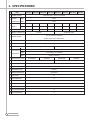
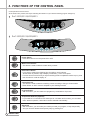
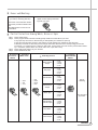
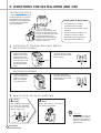
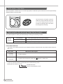
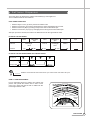
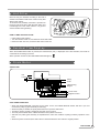
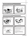
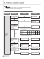
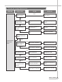
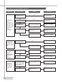
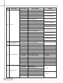
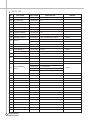
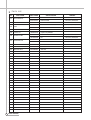
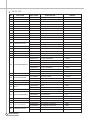
Service Manual
Auto Washer
Model : DWF-5510/5511/5520/5521
6010/6011/6020/6021
DAEWOO ELECTRONICS CO., LTD.
DAEWOO ELECTRONICS CO., LTD.
OVERSEAS SERVICE DEPT.
AUTO WASHER
ER
AUTO WASHER
WASHER
WASHER
AUTO WASHER
AUTO WASHER
AUTO WASHER
WASHER
AUTO WASHER
AUTO WASHER
AUTO WASHER
AUTO WASHER
AUTO WASHER
AUTO WASHER
AUTO WASHER
AUTO WASHER
AUTO WASHER
AUTO WASHER
AUTO WASHER
AUTO WASHER
AUTO WASHER
AUTO WASHER
AUTO WASHER
AUTO WASHER
AUTO WASHER
AUTO WASH-
AUTO WASHER
AUTO WASHER
AUTO WASH-
AUTO WASHER
2
2. STRUCTURE OF THE WASHING MACHINE
3
3. FUNCTIONS OF THE CONTROL PANEL
4
4. WASHING PROCEDURE AND COURSE SELECTION
5
7
7
5. DIRECTIONS FOR INSTALLATION AND USE
INSTALLATION OF THE UNDER BASE COVER
HOW TO INSTALL ON AN INCLINED PLACE
HOW TO CONNECT THE INLET HOSE
HOW TO CLEAN THE FILTER
8
8
9
10
6. FEATURE AND TECHNICAL EXPLANATION
FEATURE OF THE WASHING MACHINE
WATER CURRENT TO ADJUST THE UNBALANCED LOAD
AUTOMATIC WATER SUPPLY SYSTEM FOR BLANKET WASH
PULSATOR SYSTEM
AUTOMATIC DRAINING TIME ADJUSTMENT
SOFTENER DISPENSER
AUTOMATIC UNBALANCE ADJUSTMENT
CIRCULATING-WATER COURSE AND LINT FILTER
LINT FILTER
RESIDUAL TIME DISPLAY
DRAIN MOTOR
GEAR MECHANISM ASS’Y
PRINCIPLE OF BUBBLE GENERATOR
FUNCTIONAL PRINCIPLE OF BUBBLE WASHING MACHINE
11
11
11
12
12
13
14
14
15
15
15
16
16
17
7. DIRECTIONS FOR DISASSEMBLY AND ADJUSTMENT
GEAR MECHANISM ASS’Y REPLACEMENT
DRAIN MOTOR AND VALVE
BRAKE ADJUSTMENT
18
19
19
8. TROUBLE SHOOTING GUIDE
CONCERNING WATER SUPPLY
CONCERNING WASHING
CONCERNING DRAINING
CONCERNING SPINNING
CONCERNING OPERATION
9. PRESENTATION OF THE P.C.B ASS’Y
20
21
22
23
24
25
APPENDIX
WIRING DIAGRAM
PARTS DIAGRAM & PARTS LIST
CIRCUIT DIAGRAM
AUTO
AUTO WASHER
1. SPECIFICATIONS
FULL AUTOMATIC COURSE
RESERVED WASHING
PARTIAL SELECTION AMONG WASH, RINSE OR SPIN
AUTO
AUTO WASHER
AUTO WASHER
AUTO WASHER
AUTO
AUTO WASHER
AUTO WASHER
AUTO WASHER
AUTO WASHER
AUTO WASHER
AUTO WASHER
AUTO WASHER
AUTO WASHER
AUTO WASHER
AUTO WASH-
Contents
WASHING MACHINE
ER
AUTO WASHER
AUTO WASHER
AUTO WASHER
AUTO WASHER
AUTO WASHER
AUTO WASHER
AUTO WASHER
AUTO WASHER
AUTO WASHER
AUTO WASHER
AUTO WASHER
AUTO WASHER
AUTO WASHER
AUTO WASHER
AUTO WASHER
AUTO WASHER
AUTO WASHER
AUTO WASHER
AUTO WASHER
AUTO WASHER
AUTO WASHER
AUTO WASHER
AUTO WASHER
AUTO WASHER
AUTO WASHER
AUTO WASHER
AUTO WASHER
AUTO WASHER
AUTO WASHER
AUTO WASHER
AUTO WASHER
AUTO WASHER
AUTO WASHER
ER
AUTO WASHER
26
30
39
1. SPECIFICATIONS
NO.
DWF-5510
ITEM
DWF-5511
DWF-5520
1 POWER SOURCE
POWER
DWF-5521
DWF-6010
DWF-6011
DWF-6020
DWF-6021
AVAILABLE IN ALL LOCAL AC VOLTAGE
50Hz
250W
CONSUMPTION 60Hz
270W
2
MACHINE
NET
32
32.5
32.5
33
32.5
33
33
33.5
WEIGHT
GROSS
35
36
36
37
36
37
37
38
3
4 DIMENSION (WXHXD) 532X855X542 532X920X542 532X887X542 532X952X542 532X855X542 532X920X542 532X887X542 532X952X542
5 MATERIAL OF INTERNAL TUB
PLASTIC
STAINLESS STEEL
FULL AUTOMATIC 4 COURCE
6 WASHING COURSE
(FUZZY, LIGHT, HEAVY, WOOL/SUIT)
7 WATER LEVEL SELECTOR
HIGH(55l), MID(45l), LOW(31l)
8 OPERATING WATER PRESSURE
0.3kgf/cm2~8kgf/cm2 (2.94 N/cm2~78.4N/cm2)
9 MAXIMUM MASS OF TEXTILE
5.5Kg
6.0Kg
WASH
125~145(50Hz), 130~150(60Hz)
SPIN
710~725(50Hz), 760~785(60Hz)
SUIT
50(50Hz), 60(60Hz)
REVOLUTION
10
PER MINUTE
11 DIRECTION INLET VALVE
12 WATER CONSUMPTION
13 PULSATOR
14 WATER LEVEL CONTROL
15 ANTI NOISE PLATE
16 GEAR MECHANISM ASS’Y
2
BACKWARD
UPWARD
BACKWARD
APPROX. 135l/CYCLE
APPROX. 130l/CYCLE
PROVIDED WITH 6 SPOUTING HOLES FOR POWERFUL UPWARD WATER STREAM
ELECTRONICAL SENSOR
OPTION
SPUR GEAR
17 LINT FILTER
O
18 SOFTENER INLET
O
19 ALARM SIGNAL
O
20 AUTO. WATER SUPPLY
O
21 FUNCTION FOR BUBBLE
OPTION
22 AUTO RE-FEED WATER
O
23 AUTO POWER OFF
O
SPECIFICATIONS
UPWARD
3. FUNCTIONS OF THE CONTROL PANEL
Control panel has micom sensor.
As the buttons are pressed, the lamps indicating the selection of your desired washing program will light up.
§ è Dwf-5510/5511/6010/6011
DAEWOO AUT OMAT IC WASHER
FUZZY
ADD
HIGH
LIGHT
WASH
HEAVY
RINSE
SUIT
SPIN
START
/ HOLD
HOT
MID
POWER
COLD
LOW
RES.
WAT
E
LEV R
EL
P
RES.
COURSE
PROCE
TEM
SS
§ è Dwf-5520/5521/6020/6021
DAEWOO AUT OMAT IC WASHER
FUZZY
ADD
LIGHT
WASH
HEAVY
RINSE
SUIT
SPIN
HIGH
POWER
COLD
LOW
RES.
WAT
E
LEV R
EL
P
RES.
COURSE
PROCE
SS
TEM
POWER
Power Switch
• Press this button to turn the power ON or OFF.
WATER
LEVEL
Water Level Selector
• This button is used to select the water level you want.
RES.
Reservation Button
• If you want to reserve the finishing time of washing, use this button.
As this button is pressed, digit in display increases by 1 hour at one press.
• If current time is 8:00 am and you expect washing will be completed around 5:00 pm, press
this nine times in order to display ‘9’.
COURSE
Course Selector
• This button is used to select the washing course according to the type of wash loads.
• Either WOOL or SUIT course is adopted to your washing machine.
PROCESS
Program Button
• With this button, you can create new programs by combinations of process.
TEMP
START
/ HOLD
4
START
/ HOLD
HOT
MID
CONTROL PANEL
Temperature Selector (Optional)
• If your washer is connected to two water taps for cold water and hot water, you can select
them. Without operation, cold water would be selected automatically.
Start/Hold
• With this button, you can make your washer proceed your program, or stop temporarilly.
And you can also release the temporary stop by pressing this.
§ è Reserved Washing
1 Set your program as the above
procedure, remaining last step.
2 Press reservation button until the
digital monitor displays the finishing time you want.
• Press the course selection button.
• Press the procedure selection button.
• But WOOL/SUIT course can not
reservation.
3 Press Start/Hold to start.
START
/ HOLD
RES.
§ è Partial Selection Among Wash, Rinse or Spin
step 1. Press power switch.
step 2. Press program button until the indicating lamps make the combinations you want.
If only spin lamp is turned on, that means you will operate your washer for spin only.
If rinse and spin lamp are turned on, that means you will operate your washer for rinse and spin.
If add lamp is turned on with other porcess lamps, that means the time of the corresponding porcess will
increase by 1~2 minutes, that is, if add is on with wash, rinse and spin, the time of each precess will increase
by 1~2 minutes. (Wash: add 2 min., Rinse: add 1 min., Spin: add 1 min.)
step 3. Press water level selector as your decision.
step 4. Press Start/Hold to start.
1 Processing
the Power
Switch
2 Selecting
Water level
Wash & Rinse
& Spin
Only Spin
Add & Wash
§ HIGH
§ MID
§ LOW
§
§
§
§
ADD
WASH
RINSE
SPIN
Add & RInse
& Spin
POWER
WATER
LEVEL
4 Pressing
the Start/Hold
Switch
3 Selecting Course
PROCESS
Add & Spin
Add & Wash
& Rinse & Spin
Only Wash
Rinse & Spin
§
§
§
§
ADD
WASH
RINSE
SPIN
§
§
§
§
ADD
WASH
RINSE
SPIN
§
§
§
§
ADD
WASH
RINSE
SPIN
§
§
§
§
ADD
WASH
RINSE
SPIN
§
§
§
§
ADD
WASH
RINSE
SPIN
§
§
§
§
ADD
WASH
RINSE
SPIN
§
§
§
§
ADD
WASH
RINSE
SPIN
§
§
§
§
ADD
WASH
RINSE
SPIN
End of
Washing
START
/ HOLD
It is Informed
by buzzer.
PROCEDURE
7
5. DIRECTIONS FOR INSTALLATION AND USE
Installing Place
Install the washer on a horizontal solid floor. If the washer is
installed on an unsuitable floor,
it could make considerable
noise and vibration.
10Cm
Never install in these places
Keep the machine body more
than 25cm apart from the wall
surface. It will make easy cleaning the drain filter which is
equipped at the back side of it.
And if it comes into contract
vibration may occur.
¡ The place where it would be
exposed to direct sunlight.
¡ The place nearby a heater or heat
appliance.
¡ The place where it would be supposed to be frozen in winter.
¡ The kitchen with coal gas and a
damp place like a bathroom.
§ è Installation Of The Under Base Cover [Option]
-DWF-5510/5511/5010/6011
1 Before installing your
washer, remove the
pad from the bottom
of the cabinet. Then,
separate under cover
from rear side of cabinet by unscrewing
and insert it into the
base.
2 Push the under-base
cover into the end, which
decrease the noise made
by this washer.
SCREW
-DWF-5520/5521/6020/6021
1 There is under-base
cover in the tub of the
washer. Put out and
draw it in its proper
site. (See picture)
2 Push the under-base
cover into the end, which
decrease the noise made
by this washer.
§ è How To Install On An Inclined Place
1
Horizon
Setting
After controlling the height
by turning the adjustable
leg, let the washer put
down to the ground.
2
Check the Horizon
Status
Check the position of tub above
the center of the washer.
NOTES
The openings must not
be obstructed by carpeting when the washing
machine is installed on a
carpeted floor.
8
DIRECTIONS
6. FEATURE AND TECHNICAL EXPLANATION
Feature of the Washing Machine
1
2
3
4
5
6
The first air bubble washing system in the world.
Quiet washing through the innovational low-noise design.
The wash effectiveness is much more enhanced because of the air bubble washing system.
The laundry detergent dissolves well in water because of the air bubble washing system.
The adoption of the water currents to adjust the unbalanced load.
One-touch operation system.
Water Current to Adjust the Unbalanced Load
It is a function to prevent eccentricity of the clothes after wash by rotating pulsator C.W and C.C.W for 35
seconds.(But, the SUIT course have no operation of the water currents to adjust the unbalnced load.)
EFFECT
It reduces vibration and noise effectively while spinning.
WATER FLOW
WASH
DRAIN
MOTOR
C.W
SINGAL
C.C.W
TIME(SEC.)
SPIN
0.4
FILL
0.4
RINSE 1
0.4
DRAIN
0.4
SPIN
0.4
FILL
RINSE 2
0.4
•••••••
DRAIN
•••
40 SEC. (About 25 Times)
* When the water level is “HIGH”
Automatic Water Supply System For Blanket Wash
The water level would be lowered because the blanket absorbs water at the beginning of washing. Therefore, after
60 seconds, the operation is interrupted to check the water level, and then the water is supplied again until the selected water level is reached.
EXPLANATION
11
Pulsator System
When the pulsator is rotated C.W or C.C.W at a high speed, it makes the cyclone water flow from the asymmetrically
designed pulsator as shown below.
Asymmetrically designed pulsator
makes the cyclone water flow, which get
rid of the washing dead zone to
increase the washing effect and reduce
the entanglement of laundry.
Automatic Drainning time Adjustment
This system adjusts the draining time automatically according to the draining condition.
Good draining
The washer begins spin process after drainage.
Bad draining
Draininig time is prolonged.
No draining
Program is stopped and gives the alarm.
Draining
condition
FUNCTIONAL PRINCIPLE
1
The micom can remember the time from the begining of drain to reset point when the pressure switch reaches to
“OFF” point
Drain Time
Movement of the Program
Less than
Continue draining
10 minutes
More than
Program stops and gives the alarm with
blinked on display lamp.
10 minutes
2
12
In case of continuous draining, residual drain time is determined by micom.
Draining time as a whole = D + 30
Residual drain time.
The time remembered by micom.
EXPLANATION
Softener Dispenser
This is the device to dispense the softener automatically by centrifugal force.
This is installed inside the auto-balancer.
FUNCTIONAL PRINCIPLE
1
2
3
4
Softener stays in room (A) when poured into softener inlet.
Softener moves from (A) to (B) by centrifugal force during intermittent spin process.
Softener flows from (B) to (C) during rinse process next to intermittent spin.
Softener moves from (C) to (D) by centrigfugal force during second intermittent spin.
After spin process is finished, the softener is added into the tub through softener outlet.
FLOW OF THE SOFTENER
Wash
Normal
Course
Intermittent
Spin
Centrifugal
force
(A)
Hold
Intermittent
Spin
Rinse
Flow in
Centrifugal
force
Flow in
(B)
(C)
Spin
(D)
FLOW OF THE SOFTENER INSIDE OF THE BALANCER
Room inside
the balancer
A
B
C
D
Centrifugal force
Flowing by weight
NOTES
Softener moves into the next room when r.p.m of the tub is more than 100 r.p.m.
HOW TO CHECK MOVEMENT
Pour a reasonable amount of “MILK” into softener dispenser and operate the washer with no load. In final
rinse cycle, make sure that the milk is added into the
tub through softener outlet.
Balancer
Softener
outlet
B
A
D
C
Softener inlet
EXPLANATION
13
Automatic Unbalance Adjustment
This system is to prevent abnormal vibration during intermittent spin and spin process.
FUNCTIONAL PRINCIPLE
When the lid is closed, the safety switch
contact is “ON” position.
2 In case that wash loads get uneven during
spin, the outer tub hits the safety switch
due to the serious vibration, and the spin
process is interrupted.
3 In case that P.C.B. ASS’Y gets “OFF” signal
from the safety switch, spin process are
stopped and rinse process is started automatically by P.C.B. ASS’Y.
4 If the safety switch is operated due to the
unbalance of the tub, the program is
stopped and the alarm is given.
Contact of safety switch Lid closing
1
Lid opening
Contact lever A
Position of
unbalanced load (OFF)
Normal (ON)
NOTES
The alarm finished when you close the lid after opening
it. Check the unbalance of the wash load and the installation condition.
Circulating-Water Course and Lint Filter
CIRCULATING-WATER
The washing and rinsing effects have been
improved by adopting the water system in
which water in the tub is circulated in a
designed pattern.
When the pulsator rotates during the washing
or rinsing process, the water below the pulsator vanes creates a water currents as shown
in figure.
The water is then discharged from the upper
part of the tub through the water channel.
About 40 L/min. water is circulated at the ‘high’
water level, standard wash load and standard
water currents.
14
EXPLANATION
Filter
Tub
Water
channel
Pulsator
Outer tub
Lint Filter
Much lint may be obtained according to the kind of
clothes to be washed and some of the lint may also
sticks to the clothes.
To minimize this possibility a lint filter is provided on
the upper part of the tub to filter the wash water as it
is discharged from the water channel. It is good to
use the lint filter during washing.
Filter
Filter
Bleach
Bleach
Inlet
Inlet
Pulsator
Pulsator
HOW TO REPLACE LINT FILTER
1 Pull the filter frame upward.
2 Turn the lint filter inside out, and wash the lint off with water.
3 Return the filter as it was, and fix the filter frame to the slot.
Residual Time Display
When the START/HOLD button is pressed, the residual time (min.) is displayed on the time indicator, and it will be
counted down according to process.
When operation is finished, the TIME INDICATOR will light up
.
Drain Motor
STRUCTURE
Pull
Loosen
Pulley
Lever
Inductive ring
Magnet
Coil of motor
Magnet of motor
FUNCTIONAL PRINCIPLE
1 When the DRAIN MOTOR connected to the power source, the DRAIN MOTOR rotates with 900 r.p.m and
revolves the pulley by gear assembly for reducing.
2 When the pulley is rotated, the pulley winds the wire to open the drain valve.
3 Therefore, rotation of pulley changed to the linear moving of wire.
4 The wire pulls the brake lever of Gear Mechanism Ass’y within 5 seconds.
5 After the wire pulled, gear assembly is separated from motor and condition of pulling is held by operation of the
lever.
6 When the power is turned off, the drain valve is closed because the wire returns to original position.
EXPLANATION
15
Gear Mechanism Ass’y
The proper water currents is made by the rotation of pulsator at a low speed to prevent the damage to the small
sized clothes.
Pulsator shaft
Spin shaft
One way clutch
bearing
Gear unit as
Sun gear
Internal gear
Planetary gear
Clutch spring
Brake lever
Clutch boss
Gear pulley
Motor
Pulsator
1490 r.p.m
(50Hz)
Gear unit as
1 revolution
Motor
Pulsator
Gear Unit as
Gear Pulley
5 revolutions
138 r.p.m
720 r.p.m
Tub
Gear pulley
Directly
720 r.p.m
V-belt
Principle of Bubble Generator
STRUCTURE
Bobbin & coil
Armature
Magnet
Bellows
Trans core
Air
Air
Air out hole
Protector A
Air in hole
Protector B
16
EXPLANATION
PRINCIPLE OF INTAKE & OUTLET OF THE AIR
INTAKE : ARMATURE moves up, and BELLOWS inhales the air. At the same time, protector B is open and A is
close.
OUTLET : ARMATURE moves down, and BELLOWS exhausts the air. At the same time, protector B is close and A
is opend.
FUNCTIONAL PRINCIPLE OF TRANS & MAGNET
¡ The phase of A.C electric power changes to 60 cycle/second.
¡ The magnetic pole of trans core is changed by the change of the phase of A.C electric power.
¡ The core repeats push and pull (3600 times/min.) of the at mature magnet.
A.C
A.C
N
S
LEAF SPRING
NS
TRANS CORE
NS
S
N
MAGNET
Functional Principle of Bubble Washing Machine
ACROSS SECTION
Air bubble
Tub
Outer tub
Pulsator
Nozzle
FUNCTIONAL PRINCIPLE
Bubble generator supplies the air from the bottom of outer tub to the inner space of pulsator, the air is dispersed by
the rotation of pulsator. Air-bubble is created by the centrifugal force, and rises up.
EXPLANATION
17
7. DIRECTIONS FOR DISASSEMBLY AND ADJUSTMENT
Warning
BEFORE ATTEMPTING TO SERVICE OR ADJUST ANY PART OF THE WASHING MACHINE, DISCONNECT THE POWER CORD FROM THE ELECTRIC OUTLET.
Gear Mechanism Ass’y Replacement
¡ Raise the top plate on the outer cabinet.
¡ Remove outer tub cover from the tub ass’y.
¡ Loosen the pulsator mounting screw and remove
the pulsator.
Pulsator Mounting screw
Outer tub cover
¡ Remove the spinner shaft flange nut by using ‘T’
¡ Remove the tub ass’y.
type box wrench.
"T" type box
wrench
Washer
Nut-spin
shaft fixing
pulsator
Nut-spin shaft fixing
Washer-spin
Shaft fixing
Tub ass'y
¡ Lay the front of the washer on the floor.
¡ Remove four bolts mounting the plate-gear protect
¡ Remove four bolts mounting the gear mechanism
by using a box wrench and remove plate-gear protect.
¡ Remove the V-belt.
¡ Pull out the gear mechanism ass’y.
ass’y by using a box wrench.
Gear mechanism
ass'y
Mounting bolt
Mounting bolt
NOTES
To assemble the gear mechanism ass’y, reverse
the disassembly procedure.
18
DIRECTIONS
Drain Motor and Valve
¡ Lay the front of the washer on the floor.
¡ Loosen the adjustment screw and two bolts
mounting the drain motor.
¡ Take out the wire of drain motor from the bracket.
¡ Separate the drain motor from the bracket.
¡ Turn the valve lid by using screw driver as shown
in figure and remove the valve lid from the valve
frame.
Drain motor
Valve frame
Bracket
Wire Bracket
Adjustment
screw
Adjustment
screw
Screw dirver
Valve lid Pin Bellows
Valve lid
Brake Adjustment
¡ Loosen the adjustment screw fastening the bracket and place the adjustment screw to the brake
lever as shown in figure.
¡ Tighten the adjustment screw completely.
¡ Tighten the link brake screw completely.
Link brake
Adjustment
screw
3.0mm
Brake lever
Brake lever
Clutch lever
Clutch lever
Adjustment bolt
Adjustment bolt
(Non pump model)
(Pump model)
¡ Loosen the adjustment bolt and turn the adjustment bolt until the end of the bolt touches to the
brake lever.
¡ Tighten the lock nut and apply a small amount of
paint-lock.
Adjustment bolt
Clutch lever
Brake lever
NOTES:
1. The brake adjustment has been made at the
factory, so that it is not re-adjust.
However, in case of insufficient brake operation,
problem the upper procedure.
2. Overtightening of the adjustment bolt will cause
poor brake performance.
3. Undertightening of the adjustment bolt will
cause continuous braking and thereby.
cause the problems of the motor during the
spingcycle.
Gear mechanism ass'y
DIRECTIONS
19
8. TROUBLE SHOOTING GUIDE
NOTES
1. When replace the P.C.B. ASS’Y do not scratch the surface of the P.C.B. ASS’Y.
2. Disconnect the power cord from the electric outlet.
Concerning Water Supply
PROBLEM
CHECK POINT
CAUSE
Do you open the water
tap?
NO
SOLUTION
Open the water tap.
YES
YES
Is the filter of the water
inlet valve clogged with
dirt?
Clean the filter.
NO
WATER IS
NOT SUPPLIED.
Increase the water pressure.
NO
Is the water pressure
sufficient?
(0.3~8 kgf/cm2)
NOTE : Open the water tap fully and measure
the flow rate.
Flow
rate(l/min.)
Water pressure
(Kgf/cm2)
YES
11.5
15.0
18.0
20.3
24.1
27.4
0.3
0.4
0.5
0.6
0.8
1.0
From the upper results, you know that the flow rate more than
11.5l/min. is essential for water supply.
Does the water inlet
valve make operating
sound?
NO
Water inlet valve
is defective.
Change water inlet valve.
Improper connection of
the connector or the terminal.
Connect the connector or
the terminal properly.
P.C.B AS is defective.
Change the P.C.B AS.
Lead wire is defective.
Change the lead wires.
YES
Is the connector or the
terminal connected
properly?
NO
YES
Is the output voltage of
the P.C.B normal?
NO
YES
20
TROUBLE SHOOTING
PROBLEM
CHECK POINT
Does the water supply
continue while the power
is turned off?
CAUSE
SOLUTION
YES
The water inlet valve is
defective.
Change the water inlet
valve.
YES
The triac of P.C.B is
defective.
Change the P.C.B ASS’Y.
NO
Does the water supply start
as soon as you press the
power switch?
NO
WATER SUPPLY IS NOT
STOPPED.
Operate the washer after
setting the water level to
“HIGH”
NO
Does the water supply
continue after the water
reaches to the “HIGH”
level?
YES
Is the air tube of water
level switch kinked or
deformed?
Normal operation.
YES
NO
Air tube is defective.
Change the air tube.
Pressure switch is defective.
Change the pressure
switch.
Concerning Washing
PROBLEM
CHECK POINT
CAUSE
SOLUTION
Does the motor operate after finishing water supply?
NO
YES
Does pulsator rotate in
only one direction?
YES The triac of P.C.B is
defective.
NO
THE PULSATOR DOES
NOT ROTATE
EVEN IF THE
WATER IS
SUPPLED.
Change the P.C.B
ASS’Y.
Normal
Does the motor make
operating sound?
YES
NO
Is the motor coil disconnected?
Is the connection condition of capacitor terminal good?
YES
Is the V-belt worn out?
NO
YES
NO
Motor is defective.
Improper connection
YES
V-belt is defective.
Change the motor.
Connect the terminal
properly.
Change the V-belt.
Change the motor.
TROUBLE SHOOTING
21
Concerning Draining
PROBLEM
CHECK POINT
Do you install the
drain hose properly?
CAUSE
NO
SOLUTION
Improper installation
Install the drain hose
properly.
Malfunction of drainage
by the foreign matter
Remove the foreign matter from the pump housing
Drain pump is defective
Change the Drain pump
P.C.B ASS’Y is defective.
Change the P.C.B ASS’Y.
YES
THE WASHER
DOES NOT
DRAIN.
Is the foreign matter
accumulated inside
the pump housing?
YES
NO
Is the output voltage of
the drain pump normal?
YES
NO
22
TROUBLE SHOOTING
Concerning Spinning
PROBLEM
CHECK POINT
CAUSE
SOLUTION
YES
Close the lid.
Is the lid open?
NO
Does the safety switch
operate normally?
NO
Safety switch is defective.
Change the safety
switch.
NO
Improper connection of
the connector.
Connect the connector
properly.
P.C.B. ASS’Y is defective.
Change P.C.B ASS’Y.
Drain motor is defective.
Change the drain motor.
P.C.B ASS’Y is defective.
Change the P.C.B ASS’Y.
V-belt is defective.
Change the V-belt.
Motor is defective.
Change the motor.
Improper connection.
Connect the terminal correctly.
P.C.B ASS’Y is defective.
Change the P.C.B ASS’Y.
YES
Is the connector of
P.C.B ASS‘Y connected
properly?
YES
Does the pulsator rotate
while the tub does not
rotate?
NO
THE WASHER
DOES NOT
SPIN.
YES
Is the input
voltage of the drain
motor normal?
YES
NO
YES
Is the V-belt worn out?
NO
Is the input voltage of
motor normal?
YES
NO
Is the connection condition of capacitor terminal good?
NO
YES
TROUBLE SHOOTING
23
Concerning Operation
PROBLEM
CHECK POINT
CAUSE
SOLUTION
NO
Is the plug connect-ed
to electric outlet?
Connect the plug.
YES
YES
THE INDICATOR
LAMPS(L.E.D)
DO NOT LIGHT
UP WHEN THE
POWER BUTTON IS
PRESSED.
Is Fuse opended?
Change Fuse
NO
Is the condition of
power button good?
NO
MOTOR
ROTATES
WHEN
START/HOLD
BUTTON IS
NOT
PRESSED.
ABNORMAL
NOISE DURING WASH
PROCESS.
Is the connector of the
P.C.B. ASS’Y connected properly?
NO
Do you press
START/HOLD button?
TROUBLE SHOOTING
Improper connection of
the connector.
Connect the connector
properly.
P.C.B. ASS’Y is defective.
Change P.C.B ASS’Y.
NO
YES
Does the pressure switch
operate normally?
NO
Check the output voltage
of P.C.B ASS’Y
Is the strange noise generated when the pulsator
rotates in TEST MODE
of P.C.B ASS’Y?
Press START/HOLD button.
P.C.B ASS’Y is defective.
Replace P.C.B ASS’Y.
Pressure switch is defective.
Change the pressure
switch.
Abnormal
YES
YES
P.C.B ASS’Y is defective
Change P.C.B ASS’Y.
There is foreign matter
between pulsator and
tub.
Remove the foreign matter.
V-belt is defective.
Change the V-belt.
NO
YES
Is the V-belt worn out?
24
Change P.C.B ASS’Y.
YES
YES
PROGRESS
LAMPS(LED)
DO NOT LIGHT
UP.
Power button is defective
9. PRESENTATION OF THE P.C.B ASS’Y
Concerning Error Message
MESSAGE
CAUSE
SOLUTION
Improper installation of drain hose.
Install drain hose properly.
The drain hose is blocked up by foreign
matter.
Remove foreign matter from drain hose.
Drain motor is inferior.
Change drain motor.
The water tap is closed.
Open the water tap.
The water inlet filter clogged.
Clean the water inlet filter.
It passes over the 30 minutes, yet it doesn’t
come to assigned water level.
Check whether or not is comes to the
assigned water level.
Wash loads get uneven during spin.
Re-set wash loads evenly.
Poor installation of the unit.
Proper installation.
The lid is opened.
Close the lid.
The safety switch is inferior.
Change the safety switch.
The load sensing is inferior. After the load
sensing operates about 7 seconds, the
message is displayed during 1 second and
water level is always fixed ‘high’.
The water level sensing is inferior.
Change the P.C.B. ASS’Y.
Check the water level sensor and the
contact part of the connector.
PCB ASS’Y
25
26
WIRING DIAGRAM
C
B
A
100~127
220~240
100~127
220~240
110
120~127
220
230
240
SYMBOL RATING(V)
SPEC
250V/8A
250V/4A OR 5A
600mA
315mA
33.6µF
30µF
8.4µF OR 9.4µF
9.4µF
8.4µF
APPENDIX
§ è Wiring Diagram [non-pump]
C
B
A
100~127
220~240
100~127
220~240
110
120~127
220
230
240
SYMBOL RATING(V)
SPEC
250V/8A
250V/4A OR 5A
600mA
315mA
33.6µF
30µF
8.4µF OR 9.4µF
9.4µF
8.4µF
§ è [Non-Pump, Single Valve]
WIRING DIAGRAM
27
28
WIRING DIAGRAM
C
B
A
100~127
220~240
100~127
220~240
110
120~127
220
230
240
SYMBOL RATING(V)
SPEC
250V/8A
250V/4A OR 5A
600mA
315mA
33.6µF
30µF
8.4µF OR 9.4µF
9.4µF
8.4µF
§ è [Pump]
SYMBOL RATING(V)
100~127
A
220~240
100~127
B
220~240
110
120~127
C
220
230
240
SPEC
250V/8A
250V/4A OR 5A
600mA
315mA
33.6µF
30µF
8.4µF OR 9.4µF
9.4µF
8.4µF
§ è [pump, single valve]
WIRING DIAGRAM
29
§ è Parts List
LOC.
A01
A02
A03
A04
PART NAME
PANEL B
VALVE INLET(HOT)
VALVE INLET(COLD)
SWITCH SAFETY AS
PART CODE
SPECIFICATION
3614219200
ABS
5510,5511,6010,6011
3614220200
ABS
5520,5521,6020,6021
3615403830
AC 220~240V/50Hz
5510,5511,6010,6011
3615403810
(NP, N, MP, M)
5520,5521,6020,6021
3615402130
AC 220V~60Hz
5510,5511,6010,6011
3615402110
(LP, L)
5520,5521,6020,6021
3615403630
AC 110~127V/60Hz
5510,5511,6010,6011
3615403610
(TP, T, SP, S)
5520,5521,6020,6021
3615403710
AC 220~240V/50Hz
5510,5511,6010,6011
3615403730
(NP, N, MP, M)
5520,5521,6020,6021
3615402010
AC 220V60Hz
5510,5511,6010,6011
3615402030
(LP, L)
5520,5521,6020,6021
3615403510
AC 110~127V/60Hz
5510,5511,6010,6011
3615403530
(TP, T, SP, S)
5520,5521,6020,6021
3615403310
AC 110V/50, 60Hz
5510,5511,6010,6011
3615403330
(J)
5520,5521,6020,6021
3619006360
DC 15V 10A
5510,5511,6010,6011
3619043600
A05
PLATE T
A06
NOZZLE DETERGENT
A07
CASE DETERGENT
A08
CAP REAR
A09
HANDLE DOOR
A10
DOOR SPRING
A11
DOOR B
A12
DOOR F
A13
WINDOW DISPLAY
A14
BRACKET
A15
UNIT CAPACITOR AS
A16
SENSER PRESSURE
A17
PANEL F
REMARK
5520,5521,6020,6021
3614515000
ABS
5510,5511,6010,6011
3614515100
ABS
5520,5521,6020,6021
3618102000
PP
5510,5511,6010,6011
3618102100
PP
5520,5521,6020,6021
3611116500
ABS
5510,5511,6010,6011
3611117200
ABS
5520,5521,6020,6021
3610902600
CR
3612603600
ABS
5510,5511,6010,6011
3612604000
ABS
5520,5521,6020,6021
3615107700
SUS304
5510,5511,6010,6011
3615108900
SUS304
5520,5521,6020,6021
3611718400
ABS
5510,5511,6010,6011
3611793300
ABS
5520,5521,6020,6021
3611718300
ABS
5510,5511,6010,6011
3611793200
ABS
5520,5521,6020,6021
3615501700
ABS
5510,5511,6010,6011
5520,5521,6020,6021
3615501800
ABS
3610602900
PP
3618911700
9.4µF, CAN TYPE
AC 220~230V/50HZ
3618911600
8.4µF, CAN TYPE
AC 240V/50Hz, AC 220V/60Hz
3618912000
33.6µF, CAN TYPE
AC 110V/60Hz
3618911900
30µF, CAN TYPE
AC 127V/60Hz
3614800960
DC 5V CDN-D7
3614219100
ABS
5510,5511,6010,6011
3614200100
ABS
5520,5521,6020,6021
PARTS DIAGRAM
31
LOC.
A18
A19
A20
A21
32
PART NAME
PCB AS
ASSY BUBBLE
CORD POWER AS
HARNESS ASSY
PARTS DIAGRAM
PART CODE
SPECIFICATION
PRPSSW8100
AC 220~230V/50Hz PUMP
PRPSSW8200
AC 220~230V/50Hz N-PUMP
PRPSSW8101
AC 240V/50Hz PUMP
PRPSSW8201
AC 240V/50Hz N-PUMP
PRPSSW8102
AC 220V/60Hz PUMP
PRPSSW8202
AC 220V/60Hz N-PUMP
PRPSSW8103
AC 110V/60Hz PUMP
PRPSSW8203
AC 110V/60Hz N-PUMP
PRPSSW8104
AC 127V/60Hz PUMP
PRPSSW8204
AC 127V/60Hz N-PUMP
PRPSSW8205
AC 100V/50,60Hz
PRPSSW8300
AC 220~230V/50Hz PUMP
PRPSSW8400
AC 220~230V/50Hz N-PUMP
PRPSSW8301
AC 240V/50Hz PUMP
PRPSSW8401
AC 240V/50Hz N-PUMP
PRPSSW8302
AC 220V/60Hz PUMP
PRPSSW8402
AC 220V/60Hz N-PUMP
PRPSSW8303
AC 110V/60Hz PUMP
PRPSSW8403
AC 110V/60Hz N-PUMP
PRPSSW8304
AC 127V/60Hz PUMP
PRPSSW8404
AC 127V/60Hz N-PUMP
PRPSSW8405
AC 100V/50,60Hz
3618946300
AC 220~240V/50,60Hz
3918946400
AC 110~127V/50,60Hz
REMARK
5510,5511,6010,6011
5510,5511,6010,6011
5510,5511,6010,6011
5510,5511,6010,6011
5510,5511,6010,6011
5510,5511,6010,6011
5520,5521,6020,6021
5520,5521,6020,6021
5520,5521,6020,6021
5520,5521,6020,6021
5520,5521,6020,6021
5520,5521,6020,6021
3611304600
LFC-3R 3X0.75 2.3M GY
AUSTRALIA, ARGENTINA
3611304700
F H05W 3X0.75 2.3M WH
CHILE
3611304800
RW-300/500 3X0.75 2.3M
PR. CHINA
3611304900
- VCTF 3X0.75 2.3M
INDIA
3611305000
R VCTFK 2X1.25 2.3M GY
JAPAN
3611305100
U VCTF 3X0.75 2.3M GY
KOREA
3611305200
P VCTF 3X0.75 2.3M GY
KUWAIT
3611305300
- VCTF 3X0.75 2.3M WH
MALAYSIA
3611305400
- H05W-F 3X0.75 2.3M BK
SINGAPORE
3611305500
A - VCTFK 2X0.75 2.3M GY
TAIWAN
3611305600
F H05W 3X0.75 2.3M BK
USSR, HUNGARY
3611305700
C SJT 3X18AWG 2.2M GY
PANAMA, USA
3611305800
H05W-F 3X0.75 2.3M GY
SOUTH AFRICA
3611305900
P VCTF 3.0.75 2.3M WH
OMAN
3612754500
NON OPTION
3612754510
NON-BUBBLE PUMP
3612754520
NON-HOT INLET VALVE
3612754530
FULL OPTION
3612754600
NON OPTION
3612754610
NON-BUBBLE PUMP
3612754620
NON-HOT INLET VALVE
3612754630
FULL OPTION
PUMP
N-PUMP
§ è Parts List
LOC.
PART CODE
SPECIFICATION
REMARK
B01
COVER UNDER
3611402700
PP
B02
PLATE UPPER
3614514900
PP
B03
COVER B
3611414010
372x508x0.4t, SGCC
B04
HOLDER SUPPORT
3613010300
FRPP, B
B05
HOLDER SUPPORT
3613010200
FRPP, FL
B06
HOLDER SUPPORT
3613010100
FRPP, FR
B07
HANDLE CABINET
3612603300
PP
B08
CABINET
3610808100
1740.2x767.4x0.6t
B09
SARNESS OUTER
3610068700
50/0.18 GREEN ST710480-2
EARTH
B10
BASE U
3610311000
PP
5510, 5520, 6010, 6020
3610311900
PP
5511, 5521, 6011, 6021
B11
FOOT
4509D10020
BUTYL RUBBER
B12
LEG ADJUST AS
3617702200
DWF-5591DPN
HOSE DRAIN O
3613217800
PE-LD
PUMP
HOSE DRAIN O AS
3613213500
EVA L=950
N-PUMP
GUIDE DRAIN HOSE
3612502300
PP
PUMP
CLAMP HOSE O
3611202200
HSW-3
PUMP
CLAMP
3611201000
HSW-3, MFZN D36
N-PUMP
COVER PUMP
3611405320
PP
PUMP
3963514000
AC 220~240V/50Hz
MOTOR SHADED
3963514010
AC 220V/60Hz
POLE
3963514020
AC 110V/60Hz
3963514030
AC 127V/60Hz
3611901530
DWF-5590DPNF, E-TYPE
B13
B14
B15
B16
B17
B18
34
PART NAME
FILTER AS
PARTS DIAGRAM
PUMP
PUMP
§ è Parts List
LOC.
36
PART NAME
PART CODE
SPECIFICATION
REMARK
3616104500
DWF-5510PN
5510,5511,5520,5521
3616104700
DWF-6010PN
6010,6011,6020,6021
4505E05050
5.2x18
3618808100
PP
5510,5511,5520,5521
3618808500
SUS
6010,6011,6020,6021
TUB U
3618808600
PP
6010,6011,6020,6021
C05
FILTER AS
4505E82002
PE(90*120) INSERT
3612503900
PP
5510,5511,5520,5521
C06
GUIDE FILTER
3612506700
PP
6010,6011,6020,6021
3619704200
DWF-5510PN
5510,5511,5520,5521
C07
PULSATOR AS
3619704600
DWF-6010PN
6010,6011,6020,6021
C08
SC. PULSATOR FIX AS
4505E3203A
6x26.5, O-RING+SILICON
C09
CAP PULSATOR
3610909300
PP
C10
SPECIAL NUT
4507D83080
SUS 304
C11
SPECIAL WASHER
3616006500
SUS 304
C12
FLANGE TUB
4505E05021
ADC-10
C13
SPECIAL SCREW
4505E05040
5x24
C01
BALANCER AS
C02
SPECIAL SCREW
C03
TUB I
C04
PARTS DIAGRAM
§ è Parts List
LOC.
PART CODE
SPECIFICATION
REMARK
D01
COVER TUB O
3611414600
PP
D02
TUB O
3618807600
PP
D03
SUSPENSION AS F
3619802300
DWF-5510NP
D04
SUSPENSION AS B
3619802400
DWF-5510NP
D05
NOZZLE BODY
3618101400
PP
D06
HOSE DRAIN I
3613220600
TPE
PUMP
D07
HOSE OVERFLOW
3613220700
L=245
N-PUMP
D08
VALVE DRAIN AS
3615404020
5591D, VE
N-PUMP
D09
HOSE DRAIN I AS
3613221800
DWF-5510N
N-PUMP
D10
BASE
3610302900
SECEN 1.6t
D11
SPECIAL BOLT BASE
4505E83100
6.5x23
D12
HARNESS SUB AS
3612754900
SUB HARNESS+EARTH
PUMP
3612754910
SUB HARNESS+EARTH
N-PUMP
D13
HOSE
4500D08220
ID=8, L=20
CAVITATION HOSE
D14
CLAMP
4500D08180
SWC BUBB PIE=8
D15
HOSE
4500D08220
ID=8, L=30
D16
CLAMP
4500D08180
SWC BUBB PIE=8
D17
HARNESS EARTH INNER
3612755700
L=180
CHILE
3966010270
AC 220~240V/50Hz
PUMP
3966010260
AC 220~240V/50Hz
N-PUMP
3966320370
AC 220V/60Hz
PUMP
3966320360
AC 220V/60Hz
N-PUMP
450ED45170
AC 110~127V/60Hz
PUMP
450ED45176
AC 110~127V/60Hz
N-PUMP
3966130260
AC 100V/50,60Hz
N-PUMP
3617801010
PP
PUMP
3617306000
GM-4900-KJ4XO
N-PUMP
PUMP
D18
SYNCRONOUS MOTOR
BUBBLE HOSE
D19
LINK BRAKE
D20
GEAR MECHANISM
3617306010
GM-4900-KJ4PO
D21
BOLT HEX
7640802011
6B-1 8x20 SW MFZN
D22
PROTECTOR GEAR
3618301300
SBHG 1.6t
D23
BELT V
4507D34020
M 20
50Hz
4507B34020
M19.5
60Hz
D24
SPECIAL WASHER
4505E34030
PP
3964340100
AC 220~240V/50Hz
NP, N, MP, M
3964340200
AC 220V/60Hz
LP, L
3964340300
AC 10~127V/60Hz
TP, T, SP, S
D25
38
PART NAME
MOTOR CONDENSER
D26
SPECIAL WASHER
4505E34040
PP
D27
BOLT HEX
7650802511
6B-1 8X25 HS MFZN
D28
PULLY MOTOR AS
3618401420
M-TYPE DS=10 DP=53.0
50Hz
3618402800
M-TYPE DS=10 DP=48.5
60Hz
D29
HARNESS SUB AS
3612754900
SUB HARNESS + EARTH + PUMP
PUMP
3612754910
SUB HARNESS + EARTH
N-PUMP
PARTS DIAGRAM
Serv ce Manual
OVERSEAS SERVICE DEPT.
DAEWOO ELECTRONICS CO., LTD.
686, AHYEON-DONG MAPO-GU SEOUL, KOREA
C.P.O. BOX 8003 SEOUL, KOREA
TELEX: DWELEC K28177-8
CABLE: “DAEWOOELEC”
FAX: 02) 590-6291
TEL: 02) 360-7114/590-6151~5
http://www.dwe. daewoo.co.kr
S/M NO. :
PRINTED DATE: NOV.1997