1
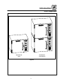
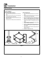
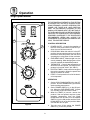
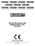
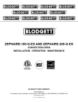
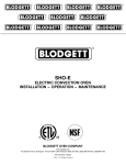
ZEPHAIRE 50E
ELECTRIC CONVECTION OVEN
INSTALLATION -- OPERATION -- MAINTENANCE
BLODGETT OVEN COMPANY
www.blodgett.com
44 Lakeside Avenue, Burlington, Vermont 05401 USA Telephone (800) 331-5842, (802) 860-3700 Fax: (802)864-0183
PN 30454 Rev C (6/01)
E 2000 --- G.S. Blodgett Corporation
IMPORTANT
WARNING: IMPROPER INSTALLATION, ADJUSTMENT,
ALTERATION, SERVICE OR MAINTENANCE CAN CAUSE
PROPERTY DAMAGE, INJURY OR DEATH. READ THE INSTALLATION, OPERATING AND MAINTENANCE INSTRUCTIONS THOROUGHLY BEFORE INSTALLING OR
SERVICING THIS EQUIPMENT
FOR YOUR SAFETY
Do not store or use gasoline or other flammable vapors or
liquids in the vicinity of this or any other appliance.
The information contained in this manual is important for the proper
installation, use, and maintenance of this oven. Adherence to these
procedures and instructions will result in satisfactory baking results
and long, trouble free service. Please read this manual carefully and
retain it for future reference.
Errors: Descriptive, typographic or pictorial errors are subject to correction. Specifications are subject to change without notice.
THE REPUTATION YOU CAN COUNT ON
For over a century and a half, The Blodgett Oven Company has been building
ovens and nothing but ovens. We’ve set the industry’s quality standard for all
kinds of ovens for every foodservice operation regardless of size, application
or budget. In fact, no one offers more models, sizes, and oven applications
than Blodgett; gas and electric, full-size, half-size, countertop and deck, convection, Cook’n Hold, Combi-Ovens and the industry’s highest quality Pizza
Oven line. For more information on the full line of Blodgett ovens contact your
Blodgett representative.
Model:
Your Service Agency’s Address:
Serial Number:
Your oven was installed by:
Your oven’s installation was checked by:
Table of Contents
Introduction
Oven Description and Specifications . . . . . . . . . . . . . . . . . . . . . . . . . . . . . . . .
Oven Components . . . . . . . . . . . . . . . . . . . . . . . . . . . . . . . . . . . . . . . . . . . . . . .
2
3
Installation
Delivery and Location . . . . . . . . . . . . . . . . . . . . . . . . . . . . . . . . . . . . . . . . . . . . .
Electrical Connection . . . . . . . . . . . . . . . . . . . . . . . . . . . . . . . . . . . . . . . . . . . . .
Oven Assembly . . . . . . . . . . . . . . . . . . . . . . . . . . . . . . . . . . . . . . . . . . . . . . . . . .
Assembly of the stands with shelves . . . . . . . . . . . . . . . . . . . . . . . . . . . . .
oven assembly to stand . . . . . . . . . . . . . . . . . . . . . . . . . . . . . . . . . . . . . . . .
Double Sections: . . . . . . . . . . . . . . . . . . . . . . . . . . . . . . . . . . . . . . . . . . . . . .
mounting oven o 4” (10cm) legs . . . . . . . . . . . . . . . . . . . . . . . . . . . . . . . .
Caster Installation: . . . . . . . . . . . . . . . . . . . . . . . . . . . . . . . . . . . . . . . . . . . .
Leveling Oven: . . . . . . . . . . . . . . . . . . . . . . . . . . . . . . . . . . . . . . . . . . . . . . . .
Adjustments Associated with Initial Installation: . . . . . . . . . . . . . . . . . . . .
4
5
6
6
6
6
7
7
7
7
Operation
Single Speed Blower . . . . . . . . . . . . . . . . . . . . . . . . . . . . . . . . . . . . . . . . . . . . .
General Guidelines for Operating Personnel . . . . . . . . . . . . . . . . . . . . . . . . .
Suggested Times and Temperatures . . . . . . . . . . . . . . . . . . . . . . . . . . . . . . . .
8
9
10
Maintenance
Cleaning and Preventative Maintenance . . . . . . . . . . . . . . . . . . . . . . . . . . . . .
Troubleshooting Guide . . . . . . . . . . . . . . . . . . . . . . . . . . . . . . . . . . . . . . . . . . . .
11
12
Introduction
Oven Description and Specifications
Cooking in a convection oven differs from cooking
in a conventional deck or range oven since heated
air is constantly recirculated over the product by
a fan in an enclosed chamber. The moving air continually strips away the layer of cool air surrounding the product, quickly allowing the heat to penetrate. The result is a high quality product, cooked
at a lower temperature in a shorter amount of time.
Blodgett convection ovens represent the latest advancement in energy efficiency, reliability, and
ease of operation. Heat normally lost, is recirculated within the cooking chamber before being
vented from the oven: resulting in substantial reductions in energy consumption and enhanced
oven performance.
Air Flow Pattern for
Blodgett Electric Convection Ovens
Figure 1
Amperes
L1
L2
L3
Electrical
Connection
AWG*
1
25
---
25
10
208
3
25
0
25
10
5.1
220-240
1
22
---
22
10
5.1
220-240
3
22
0
22
10
KW/Section
Volts
Phase
5.1
208
5.1
60 HZ UNITS
* Refer to Page 4 in this manual for Electrical Connection specifications
NOTE: Load ratings are double the above data for Double Stacked units.
2
Introduction
Oven Components
ZEPHAIRE-50E
Single
ZEPHAIRE-50E
Double Stacked
Figure 2
3
Installation
Delivery and Location
DELIVERY AND INSPECTION
OVEN LOCATION
All Blodgett ovens are shipped in containers to
prevent damage. Upon delivery of your new oven:
The well planned and proper placement of your
oven will result in long term operator convenience
and satisfactory performance.
D
D
Inspect the shipping container for external damage. Any evidence of damage should be noted
on the delivery receipt which must be signed by
the driver.
Uncrate the oven and check for internal damage. Carriers will accept claims for concealed
damage if notified within fifteen days of delivery
and the shipping container is retained for inspection.
The following clearances must be maintained between the oven and any combustible or non-combustible construction.
D
D
D
D
The Blodgett Oven Company cannot assume
responsibility for loss or damage suffered in
transit. The carrier assumed full responsibility
for delivery in good order when the shipment
was accepted. We are, however, prepared to
assist you if filing a claim is necessary.
Adequate clearances must be available for servicing.
It is also essential that ventilation air not be obstructed in any way if proper operation is to be assured. Tripping of the blower motor thermal overload protective device is caused by excessive
ambient temperature on the control side of the
oven resulting from insufficient ventilation. Such a
condition must be corrected immediately if permanent damage to the oven is to be avoided.
ZEPHAIRE-50E OVENS ARE
PACKAGED AS FOLLOWS:
D
D
For single sections - The steam vent is packaged in the oven.
For double sections - Each oven is packed
with a steam vent.
Before making any utility connections to this oven,
check the rating plate to be sure the oven specifications are compatible with the electrical services
supplied for the oven.
If the oven is ordered with 4” legs:
D
1. The rating plate is attached to the back of the
oven.
Legs are packed with the oven.
If the oven is ordered with a stand:
The Zephaire-50E is designed for countertop use.
However, there is a procedure for mounting the
unit on a stand both as a single or a double
stacked oven.
There are three stand variations available for the
Zephaire-50E oven:
D
D
D
Oven body right side --- 0” (0 cm)
Oven body left side --- 0” (0 cm)
Oven body back --- 0” (0 cm)
Oven body bottom --- 10” (0 cm)
A 33” (83.8 cm) stand is available for a single
oven when counter space is not available. This
stand is supplied with a shelf that may be used
for temporary storage of products or utensils.
A 19” (48 cm) stand is available for a double
stacked oven when the oven is to be located on
the floor. This stand is supplied with a shelf.
A 24” (61 cm) stand is available to meet different
installation requirements.
4
Installation
Electrical Connection
STANDARDS AND CODES
ELECTRICAL CONNECTION
THE INSTALLATION INSTRUCTIONS CONTAINED HEREIN ARE FOR THE USE OF QUALIFIED INSTALLATION AND SERVICE PERSONNEL
ONLY. INSTALLATION OR SERVICE BY OTHER
THAN QUALIFIED PERSONNEL MAY RESULT IN
DAMAGE TO THE OVEN AND/OR INJURY TO
THE OPERATOR.
Ovens are supplied for operation on 208 volt or
220-240 volt installation. The electric motor, indicator lights and related switches are interconnected through the one power source supplied to
the oven.
Wiring diagrams are located in the control compartment area and included at the back of this
manual.
Qualified installation personnel are individuals, a
firm, a corporation, or a company which either in
person or through a representative are engaged
in, and responsible for:
D
The supply enters through the rear of the oven and
electrical connection is made to the terminal block
secured to the mounting panel in the control compartment. Electrical connection sizes for the oven
are shown in the “Electrical Connection AWG” column of the Electrical Specifications section in this
manual. Wiring is sized for 60_C copper wire at
125% of rated input. Reference is from the National
Electric Code ANSI/NFPA 70-1987.
the installation of electrical wiring from the electric meter, main control box or service outlet to
the electric appliance.
Qualified installation personnel must be experienced in such work, familiar with all precautions
required, and have complied with all requirements
of state or local authorities having jurisdiction.
U.S. and Canadian installations
Installation must conform with local codes, or in
the absence of local codes, with the National Electrical Code, ANSI/NFPA 70 ---Latest Edition and/or
Canadian National Electric Code C22.2 as applicable.
General export installations
Installation must conform with Local and National
installation standards. Local installation codes
and/or requirements may vary. If you have any
questions regarding the proper installation and/or
operation of your Blodgett oven, please contact
your local distributor. If you do not have a local distributor, please call the Blodgett Oven Company at
0011-802-860-3700.
5
Installation
Stand Assembly
STAND ASSEMBLY
Small Stands Without Shelves
Stands With Shelves
1. Place stand frame upside down on a work surface.
2. Attach one leg to each of the corner stud bolts
on the bottom of the stand top.
3. Place a lock washer and nut on each bolt, and
tighten. DO NOT tighten leg bolts completely.
4. Place the shelf between the legs so that the
smooth top surface is facing the top of the
stand.
5. Align the shelf holes with the bolt holes found
near the bottom of each leg.
6. Insert a carriage bolt from the outside of the
leg, through the leg, and through the shelf corner bracket.
7. Place a lock washer and nut on each bolt, and
tighten securely.
8. Tighten the leg frame bolts.
1. Place stand frame upside down on a work surface.
2. Attach one leg to each of the corner stud bolts
on the bottom of the stand top.
3. Place a lock washer and nut on each stud, and
tighten securely.
4. The stand is now ready for the oven assembly.
Figure 3
6
Installation
Oven Assembly
OVEN ASSEMBLY TO STAND
CASTER INSTALLATION:
Ovens are fastened to the stand by placing the
connecting bolts into the holes located in the front
and rear corners on the oven bottom.
Casters are available as an option for single or
double section ovens.
NOTE: Two casters with locking devices must be
installed on the front legs or the front of the
stand. Casters without locking devices
must be installed on the rear legs or the
rear of the stand.
1. Place stand in location of oven use.
2. Set a single oven on the stand and center on
the frame.
3. Locate and align bottom bolt holes front and
rear with bolt holes in stand frame.
4. Insert a bolt and washer from the bottom up
through the holes in the stand.
5. Tighten securely with a wrench.
6. Remove two existing sheet metal screws near
the rear of the vent.
7. Place steam vent over 1” x 10” (2.5 x 25.4 cm)
opening on rear panel of oven. Fasten the vent
to the oven with the five screws provided.
Adjustable leg feet may be replaced with casters
as follows:
1. Remove the leg foot assembly.
2. Insert the caster.
3. Secure the caster by tightening the lock nut
with a wrench.
LEVELING OVEN:
Whenever an oven is mounted on legs or a stand
it should be leveled by screwing the adjustable leg
feet in or out as necessary and checking with a
spirit level placed on the top of the oven.
MOUNTING OVEN O 4” (10CM) LEGS
1. Tilt the oven onto its back.
2. Screw 4” (10 cm) legs into 4 holes located
near oven corners.
3. Lift oven forward onto legs.
Figure 4
7
Installation
Oven Assembly
ADJUSTMENTS ASSOCIATED WITH INITIAL
INSTALLATION:
DOUBLE SECTIONS:
1. Double section ovens may be secured to the
stand with the same procedure as above utilizing the same four bolt holes on the bottom of
the oven.
2. Secure double stacked units together using
fastening brackets and bolts provided.
3. Seal the seam between the top and bottom
ovens with an NSF listed splash zone sealant.
4. A steam vent will be installed on each unit to
vent the ovens.
Each oven, and its component parts, have been
thoroughly tested and inspected prior to shipment. However, it is often necessary to further
test or adjust the oven as part of normal and
proper installation. Such adjustments associated with initial installation are the responsibility of the dealer or installer. Since these adjustments are not considered defects in
material or workmanship, they are not covered
under the Original Equipment Warranty. They
include, but are not limited to calibration of the
solid state temperature control, adjustment of
the doors, leveling, testing of electrical components, and tightening of fasteners. No installation should be considered complete without
proper inspection and, if necessary, adjustment by qualified installation or service personnel.
Figure 5
8
Operation
Single Speed Blower
THE INFORMATION CONTAINED IN THIS SECTION
IS PROVIDED FOR THE USE OF QUALIFIED OPERATING PERSONNEL. QUALIFIED OPERATING PERSONNEL ARE THOSE WHO HAVE CAREFULLY
READ THE INFORMATION CONTAINED IN THIS
MANUAL, ARE FAMILIAR WITH THE FUNCTIONS OF
THE OVEN AND/OR HAVE HAD PREVIOUS EXPERIENCE WITH THE OPERATION OF THE EQUIPMENT
DESCRIBED. ADHERENCE TO THE PROCEDURES
RECOMMENDED HEREIN WILL ASSURE THE
ACHIEVEMENT OF OPTIMUM PERFORMANCE AND
LONG, TROUBLE-FREE SERVICE.
2
1
3
CONTROL DESCRIPTION
1. POWER ON/OFF - Controls the operation of
the oven. If the power switch is in the OFF position the oven will be turned off.
2. COOL DOWN - When this switch is in the OFF
position, the oven can be used to cook. When
the switch is in the ON position, the oven is not
operating but cooling down for the next bake.
3. OVEN READY LIGHT - When the light is on, the
oven is preheating. When the light goes out, the
oven has reached the desired temperature.
4. THERMOSTAT - Controls the temperature at
which the oven will operate. The range of temperature is from 200_-500_F (93_-260_C).
5. ELECTRIC TIMER - Used to time the length of
the cooking operation. When the preset time
expires, a buzzer will sound.
6. FUSES - Circuit protection for all of the electrical components.
4
5
OPERATION
1. Set the COOL DOWN SWITCH (2) to the OFF
position. Turn the THERMOSTAT (4) to the desired operating temperature.
2. Set the POWER SWITCH (1) to the ON position. When the OVEN READY LIGHT (3) goes
out, load the product and set the timer.
3. When the TIMER (5) sounds. remove the
product. If the next product requires a lower
operating temperature, then the COOL
DOWN mode can be used. Turn the POWER
SWITCH (1) to the ON position and the COOL
DOWN SWITCH (2) to the ON position. Make
sure that the door is open.
4. Turn the oven off by setting the POWER
SWITCH (1) to the OFF position.
6
Figure 6
9
Operation
General Guidelines for Operating Personnel
Always preheat the oven before using by setting
the thermostat to the desired setting. The oven
has reached operating temperature when the
“LIGHT OFF OVEN READY” light goes out.
Follow the Time and Temperature recommendations provided for the product to be prepared in
the oven. Cooking at higher temperatures will not
reduce cooking time, it will produce unsatisfactory
results. Time will vary with the amount of product
loaded, the type of pan and the temperature. Record times and temperatures which provide best
results for future reference.
Five racks are provided with the oven; however, up
to nine may be used. Product or pan height determine the number of racks to be used.
10
Do not place a pan or aluminum foil on the bottom
of the oven. This will obstruct the flow of air and result in uneven baking.
When baking, weigh the product to assure equal
quantities in all pans or uneven results may occur.
For cooking, the selector switch will be placed in
the ON position and the COOL DOWN switch in
the OFF position. When placed in this mode, operation of the blower is automatically controlled by
the action of the doors. Use the ON position of the
COOL DOWN switch when the oven doors are
open to lower the temperature of the oven quickly.
Operation
Suggested Times and Temperatures
Product
Temperature
Time
# Shelves
Meats
Hamburger Patties (5 per lb)
Steamship Round (80 lb. quartered)
Standing Rib Choice (20 lbs, trimmed, rare)
Banquet Shell Steaks (10 oz. meat)
Swiss Steak after Braising
Baked Stuffed Pork Chop
Boned Veal Roast (15 lbs.)
Lamb Chops (small loin)
Bacon (on racks in 18” x 26” pans)
400_F (205_C)
275_F (135_C)
235_F (115_C)
450_F (235_C)
275_F (135_C)
375_F (190_C)
300_F (150_C)
400_F (205_C)
400_F (205_C)
8-10 mins.
2 hrs 45 mins.
2 hrs 45 mins.
7-8 mins.
1 hr.
25-30 mins.
3 hrs. 10 mins.
7-8 mins.
5-7 mins.
10
2
2
5
5
5
2
5
10
Poultry
Chicken Breast & Thigh
Chicken Back & Wing
Chicken (21/2 lbs. quartered)
Turkey Rolled (18 lb. rolls)
350_F (175_C)
350_F (175_C)
350_F (175_C)
310_F (155_C)
40 mins.
35 mins.
30 mins.
3 hrs 45 mins.
5
5
5
3
Fish and Seafood
Halibut Steaks, Cod Fish (frozen 5 oz)
Baked Stuffed Lobster (21/2 lb.)
Lobster Tails (frozen)
350_F (175_C)
400_F (205_C)
425_F (220_C)
20 mins.
10 mins.
9 mins.
5
3
5
Cheese
Macaroni & Cheese Casserole
Melted Cheese Sandwiches
350_F (175_C)
400_F (205_C)
30 mins.
8 mins.
5
10
Potatoes
Idaho Potatoes (120 ct.)
Oven Roasted Potatoes (sliced or diced)
400_F (205_C)
325_F (165_C)
50 mins.
10 mins.
5
5
Baked Goods
Frozen Berry Pies (22 oz)
Fresh Apple Pie (20 oz.)
Pumpkin Pies (32 oz.)
Fruit Crisp
Bread (24 - 1 lb. loaves)
Southern Corn Bread
Baking Soda Biscuits
Brown & Serve Rolls
Sheet Cakes (5 lb. mixed batter per pan)
Chocolate Cake
Brownies
325_F (150_C)
350_F (175_C)
300_F (150_C)
300_F (150_C)
325_F (155_C)
375_F (190_C)
400_F (205_C)
350_F (175_C)
325_F (160_C)
325_F (160_C)
325_F (150_C)
35 mins.
25-30 mins.
30-50 mins.
25 mins.
30 mins.
15-20 mins.
6 mins.
15 mins.
16-18 mins.
20 mins.
15 mins.
5 (30 pies)
5 (30 pies)
5 (20 pies)
5
3
5
5
5
5
5
5
NOTE: Actual times and temperatures may vary considerably from those shown above. They are affected
by weight of load, temperature of the product, recipe, type of pan and calibration of thermostat.
Should your recipe vary, write in your proven time and temperature for ready reference.
11
Maintenance
Cleaning and Preventative Maintenance
CLEANING THE OVEN
PREVENTATIVE MAINTENANCE
Stainless steel ovens may be kept clean and in
good condition with a light oil.
1. Saturate a cloth, and wipe the oven when it is
cold.
2. Dry the oven with a clean cloth.
The best preventative maintenance measures are,
the proper installation of the equipment and a program for routinely cleaning the ovens.
On the stainless front or interiors, deposits of
baked on splatter may be removed with any nontoxic industrial stainless steel cleaner. Heat tint
and heavy discoloration may be removed with any
non-toxic commercial oven cleaner.
1. Apply cleaners when the oven is cold. Always
rub with the grain of the metal.
Keep liquid away from the light sockets, temperature probes, heating elements, etc. Avoid spraying the oven’s electrical connections, thermostat
and light bulb receptacles.
The porcelain interior can be cleaned with any
commercial oven cleaner. Be sure caustic cleaning compounds DO NOT come in contact with the
aluminized steel panel directly behind the blower
wheel.
1. Remove the racks and rack supports from the
oven.
2. Soak the parts in a solution of ammonia and
water.
3. Reinstall after cleaning.
12
Annual Maintenance
This oven requires no lubrication, however, the
venting system should be checked annually for
possible deterioration resulting from moisture and
corrosive flue products.
If maintenance or repairs are required, contact
your local Blodgett service company, a factory
representative or the Blodgett Oven company.
WARNING!!
Always disconnect the appliance from the
power supply before servicing or cleaning.
Maintenance
Troubleshooting Guide
POSSIBLE CAUSE(S)
SUGGESTED REMEDY
SYMPTOM: Elements will not heat
S
S
S
S
Oven not plugged in.
S
S
S
S
Power switch on the control panel is off.
Control set below ambient temperature.
Doors are open.
Plug in electrical supply cord.
Set the control panel to COOK or OVEN ON.
Set to desired cook temperature.
Close doors.
SYMPTOM: Oven does not come to ready.
S The oven has not reached preheat temperature. S Wait for oven to reach preheat temperature.
S Internal problem with main temperature control. S *
SYMPTOM: Convection fan does not run.
S Oven is not plugged in.
S Circuit breaker tripped.
S Doors are open
S Plug in electrical supply cord.
S Reset the breaker.
S Close doors.
SYMPTOM: General baking problems.
S Thermostat out of calibration.
S Improper oven venting.
S *
S *
*Denotes remedy is a difficult operation and should be performed by qualified personnel only. It is recommended, however, that
All repairs and/or adjustments be done by your local Blodgett service agency and not by the owner/operator. Blodgett cannot assume responsibility for damage as a result of servicing done by unqualified personnel.
WARNING!!
Always disconnect the power supply before cleaning or servicing the oven.
13
CUSTOMER
INSERT
WIRING DIAGRAM
HERE