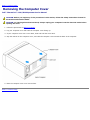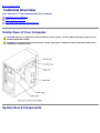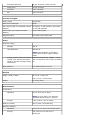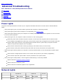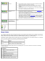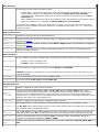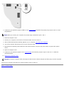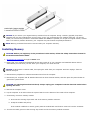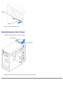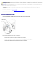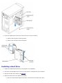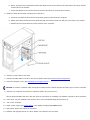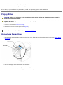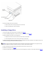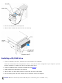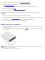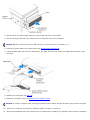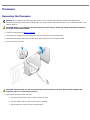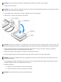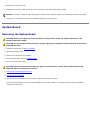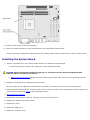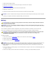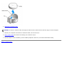
1
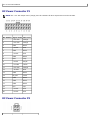
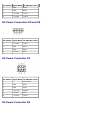
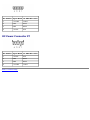
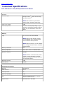
Dell™ Dimension™ 1100/B110 Systems Service Manual
Before You Begin
Removing the Computer Cover
Technical Overview
Technical Specifications
Advanced Troubleshooting
System Setup
Removing and Installing Parts
Replacing the Computer Cover
Notes, Notices, and Cautions
NOTE: A NOTE indicates important information that helps you make better use of your computer.
NOTICE: A NOTICE indicates either potential damage to hardware or loss of data and tells you how to avoid the
problem.
CAUTION: A CAUTION indicates a potential for property damage, personal injury, or death.
Abbreviations and Acronyms
For a complete list of abbreviations and acronyms, see the Dell Dimension Help file.
If you purchased a Dell™ n Series computer, any references in this document to Microsoft® Windows® operating systems are
not applicable.
Information in this document is subject to change without notice.
© 2006 Dell Inc. All rights reserved.
Reproduction in any manner whatsoever without the written permission of Dell Inc. is strictly forbidden.
Trademarks used in this text: Dell, the DELL logo, Inspiron, Dell Precision, Dimension, OptiPlex, Latitude, PowerEdge, PowerVault, PowerApp, and
Dell OpenManage are trademarks of Dell Inc.; Intel, Pentium, and Celeron are registered trademarks of Intel Corporation; Microsoft and Windows
are registered trademarks of Microsoft Corporation.
Other trademarks and trade names may be used in this document to refer to either the entities claiming the marks and names or their products.
Dell Inc. disclaims any proprietary interest in trademarks and trade names other than its own.
Model DMC August 2006 Rev. A02
Back to Contents Page
Before You Begin
Dell™ Dimension™ 1100/B110 Systems Service Manual
Getting Started
Recommended Tools
Turning Off Your Computer
Before Working Inside Your Computer
Getting Started
This chapter provides procedures for removing and installing the components in your computer. Unless otherwise noted, each
procedure assumes that the following conditions exist:
You have performed the steps in Turning Off Your Computer and Before Working Inside Your Computer.
You have read the safety information in your Dell™ Product Information Guide.
A component can be replaced or—if purchased separately—installed by performing the removal procedure in reverse
order.
Recommended Tools
The procedures in this document may require the following tools:
Small flat-blade screwdriver
Phillips screwdriver
Turning Off Your Computer
NOTICE: To avoid losing data, save and close any open files and exit any open programs before you turn off your
computer.
1. Shut down the operating system:
a. Save and close any open files, exit any open programs, click the Start button, and then click Turn Off
Computer.
b. In the Turn off computer window, click Turn off.
The computer turns off after the operating system shutdown process finishes.
2. Ensure that the computer and any attached devices are turned off. If your computer and attached devices did not
automatically turn off when you shut down your operating system, press and hold the power button for 4 seconds.
Before Working Inside Your Computer
Use the following safety guidelines to help protect your computer from potential damage and to help ensure your own
personal safety.
CAUTION: Before you begin any of the procedures in this section, follow the safety instructions located in
the Product Information Guide.
CAUTION: Handle components and cards with care. Do not touch the components or contacts on a card.
Hold a card by its edges or by its metal mounting bracket. Hold a component such as a processor by its
edges, not by its pins.
NOTICE: Only a certified service technician should perform repairs on your computer. Damage due to servicing that is
not authorized by Dell is not covered by your warranty.
NOTICE: When you disconnect a cable, pull on its connector or on its strain-relief loop, not on the cable itself. Some
cables have a connector with locking tabs; if you are disconnecting this type of cable, press in on the locking tabs
before you disconnect the cable. As you pull connectors apart, keep them evenly aligned to avoid bending any
connector pins. Also, before you connect a cable, ensure that both connectors are correctly oriented and aligned.
NOTICE: To avoid damaging the computer, perform the following steps before you begin working inside the computer.
1. Turn off your computer.
NOTICE: To disconnect a network cable, first unplug the cable from your computer and then unplug it from the
network wall jack.
2. Disconnect any telephone or telecommunication lines from the computer.
3. Disconnect your computer and all attached devices from their electrical outlets, and then press the power button to
ground the system board.
CAUTION: To guard against electrical shock, always unplug your computer from the electrical outlet before
opening the cover.
4. Open the computer cover.
NOTICE: Before touching anything inside your computer, ground yourself by touching an unpainted metal surface,
such as the metal at the back of the computer. While you work, periodically touch an unpainted metal surface to
dissipate any static electricity that could harm internal components.
Back to Contents Page
Back to Contents Page
Removing the Computer Cover
Dell™ Dimension™ 1100/B110 Systems Service Manual
CAUTION: Before you begin any of the procedures in this section, follow the safety instructions located in
the Product Information Guide.
CAUTION: To guard against electrical shock, always unplug your computer from the electrical outlet before
opening the cover.
1. Follow the procedures in Before You Begin.
2. Lay your computer on its side with the computer cover facing up.
3. If your computer cover has a cover latch, slide and hold the cover latch.
4. Grip the indents on the computer cover, and slide the computer cover toward the back of the computer.
5. Place the computer cover on a level surface.
Back to Contents Page
Back to Contents Page
Technical Overview
Dell™ Dimension™ 1100/B110 Systems Service Manual
Inside View of Your Computer
System Board Components
Power Supply DC Connector Pin Assignments
Inside View of Your Computer
CAUTION: Before you begin any of the procedures in this section, see the safety instructions located in the
Product Information Guide.
CAUTION: To guard against electrical shock, always unplug your computer from the electrical outlet before
opening the computer cover.
System Board Components
Power Supply DC Connector Pin Assignments
The 250-W power supply can operate from an AC power source of 115 VAC or 230 VAC at 50 – 60 Hz. The power supply
provides the DC operating voltages and currents listed in the following table.
Output Voltage 1
Minimum Current (A)
Maximum Current (A) 2
+12 VDC
0.0
16.0 3
+5 VDC
1.0/0.24
22.0
+3.3 VDC
0.1/0.05
18.0
-
-
-
–12 VDC
0.0
1.0
+5 VFP
0.0
2.0
1 Outputs
PAR.2.3.
will meet and not exceed SELV requirements per electrical standards, i.e. UL 60950, IEC 60950, EN60950
2 Maximum
continuous combined load on +5 VDC and +3.3 VDC outputs will not exceed 150 watts.
3 Peak
+12 VDC output power (up to 17.0 amps) will not exceed 15 seconds in duration. Under this condition, tolerance on
the +12v output, is allowed to be +/- 10%.
4 +5
VDC minimum load will be 0.2A when there is a minimum load of 0.3A on the +12 VDC and 0.42A on the +3.3 VDC
outputs simultaneously. +5V min load is 1A for load transient tests.
5 In
system applications where +3.3VDC is not used, all other outputs will stay within regulation while the +3.3 VDC output
is in a zero load condition.
DC Power Connector P1
NOTE: The +3.3 VDC output wires (orange) must be 16 AWG. All other output wires must be 18 AWG.
Pin Number Signal name Wire Color
1
+3.3 VDC
Orange
2
+3.3 VDC
Orange
3
COM
Black
4
+5 VDC
Red
5
COM
Black
6
+5 VDC
Red
7
COM
Black
8
POK
Gray
9
+5 VFP
Purple
10
+12 VDC
Yellow
11
+3.3 VDC
Orange
12
–12 VDC
Blue
13
COM
Black
14
PS_ON
Green
15
COM
Black
16
COM
Black
17
COM
Black
18
N/C
N/C
19
+5 VDC
Red
20
+5 VDC
Red
DC Power Connector P2
Pin Number Signal Name 18-AWG Wire Color
1
COM
Black
2
COM
Black
3
+12 VDC
Yellow
4
+12 VDC
Yellow
DC Power Connectors P8 and P9
Pin Number Signal Name 18-AWG Wire Color
1
+12 VDC
Yellow
2
COM
Black
3
COM
Black
4
+5 VDC
Red
DC Power Connector P4
Pin Number Signal Name 18-AWG Wire Color
1
-
No connect
2
COM
Black
3
COM
Black
4
+3.3 VDC
Orange
5
+5 VDC
Red
6
+12 VDC
Yellow
DC Power Connector P6
Pin Number Signal Name 18-AWG Wire Color
1
+12 VDC
Yellow
2
COM
Black
3
COM
Black
4
+5 VDC
Red
DC Power Connector P7
Pin Number Signal Name 22-AWG Wire Color
1
+5 VDC
Red
2
COM
Black
3
COM
Black
4
+12 VDC
Yellow
Back to Contents Page
Back to Contents Page
Technical Specifications
Dell™ Dimension™ 1100/B110 Systems Service Manual
Processor
Processor type
Intel® Pentium ® 4 with HT Technology
and Intel Celeron®
NOTE: Not all Pentium 4 processors
support Hyper-Threading technology.
Level 1 (L1) cache
8 KB
Level 2 (L2) cache
128-KB or 512-KB (depending on your
computer configuration) pipelined-burst,
eight-way set associative, write-back
SRAM
Memory
Type
333- and 400-MHz DDR SDRAM
NOTE: DDR333 and DDR400 memory
runs at 266MHz when configured with
Celeron 400MHz FSB processors
NOTE: DDR333 memory runs at 320MHz
when configured with Pentium 4 800MHz
FSB processors
Memory connectors
two
Memory capacities
128-, 256-, 512-, or 1-GB non-ECC
Minimum memory
128 MB
NOTE: Between 1 and 64 MB of system
memory may be allocated to support
graphics, depending on system memory
size and other factors.
Maximum memory
2 GB
BIOS address
F0000h
Computer Information Chip set
Intel 865 GV
DMA channels
Seven
Interrupt levels
24
BIOS chip (NVRAM)
4 Mb
NIC
integrated network interface capable of
10/100 communication.
System Clock
Intel Pentium 4: 800 MHz
Intel Celeron: 533 MHz
Video
Type
Integrated Intel Extreme Graphics 2
Audio
Type
AC97, Sound Blaster Emulation, ADI 1980
audio controller with 2.1 implementation
Expansion Bus
Bus type
PCI
Bus speed
33 MHz
PCI
connectors
three
connector size
120 pins
connector data width (maximum)
32 bits
Drives Externally accessible:
Available devices
One bay for a floppy drive, and two bays
for CD/DVD drives
Floppy drive, USB memory devices, CD
drive,
CD-RW drive, DVD drive, DVD-RW drive,
and DVD and CD-RW combo drive
Internally accessible:
One bay for 1-inch-high IDE hard drives
Connectors External connectors:
Serial
9-pin connector; 16550C-compatible
Parallel
25-hole connector (bidirectional)
Video
15-hole connector
Network adapter
RJ45 connector
PS/2 (keyboard and mouse)
6-pin mini-DIN
USB
two front-panel and four back-panel USB
2.0–compliant connectors
Audio
Three connectors for line-in, line-out, and
microphone; one front-panel connector
for headphones
System board connectors:
Primary IDE drive
40-pin connector on PCI local bus
Secondary IDE drive
40-pin connector on PCI local bus
Floppy drive
34-pin connector
CD Audio
4-pin connector
Fan
3-pin connector
Controls and Lights Power control
Push button
Hard-drive access light
Green
Link integrity light (on integrated network
adapter)
No light for 10-Mb operation; green light
for 100-Mb operation
Activity light (on integrated network
adapter)
Yellow blinking light
Diagnostic lights
Four lights on the back panel
Power
DC power supply:
Wattage
250 W
Heat dissipation
853 BTU/hr
NOTE: Heat dissipation is calculated
based upon the power supply wattage
rating.
Voltage (see the safety instructions
located in the Product Information
Guide for important voltage setting
information)
Backup battery
manual selection power supplies — 90 to
135 V at 50/60 Hz; 180 to 265 V at 50/60
Hz
3-V CR2032 lithium coin cell
Physical
Height x width x depth
41.9 x 18.1 x 36.8 cm
(16.5 x 7.13 x 14.50 inches)
Weight
11.34 kg (25 lb)
Environmental Temperature:
Operating
10º to 30ºC (50º to 86ºF)
NOTE: At 30°C (86°F), the maximum
operating altitude is 914 m (3000 ft).
Storage
Relative humidity
–40º to 65ºC (–40 º to 149ºF)
20% to 80% (noncondensing)
Maximum vibration:
Operating
0.25 G at 3 to 200 Hz at 0.5 octave/min
Storage
2.20 Grms at 10 to 500 Hz at 1
octave/min
Maximum shock:
Operating
105 G, 2 ms
Storage
32 G with a velocity change of 596.9
cm/sec (235 inches/sec)
Altitude:
Operating
–15.2 to 3048 m (–50 to 10,000 ft)
NOTE: At 30°C (95°F), the maximum
operating altitude is 914 m (3000 ft).
Storage
Back to Contents Page
–15.2 to 10,670 m (–50 to 35,000 ft)
Back to Contents Page
Advanced Troubleshooting
Dell™ Dimension™ 1100/B110 Systems Service Manual
Power Lights
Network Lights
Diagnostic Lights
Beep Codes
System Messages
Power Lights
The power button light located on the front of your computer illuminates and blinks or remains solid to indicate different
states:
If the power light is green, the power status is good and the computer is functioning properly.
If the power light is green and the computer is not responding, see Network Lights.
If the power light is blinking green, the computer is in standby mode. Press a key on the keyboard or move the mouse
to resume normal operation.
If the power light is off, the computer is either turned off or is not receiving power.
Reseat the power cable into both the power connector on the back of the computer and the electrical outlet.
If the computer is plugged into a power strip, ensure that the power strip is plugged into an electrical outlet and
that the power strip is turned on. Also bypass power protection devices, power strips, and power extension
cables to verify that the computer turns on properly.
Ensure that the electrical outlet is working by testing it with another device, such as a lamp.
Ensure that the main power cable and front panel cable are securely connected to the system board.
If the power light is blinking amber, the computer is receiving electrical power, but an internal power problem might
exist.
Ensure that the voltage selection switch is set to match the AC power at your location (if applicable).
Ensure that the processor power cable is securely connected to the system board.
If the power light is steady amber, a device might be malfunctioning or incorrectly installed.
Remove and then reinstall the memory modules.
Remove and then reinstall any cards.
Remove and then reinstall the graphics card, if applicable.
Network Lights
100 Mb Link
10 Mb Link
Active
Non-active
Active
Non-active
blinking
on
blinking
on
No Link
off
Yellow LED
Green LEG
on
on
off
off
off
Diagnostic Lights
CAUTION: Before you begin any of the procedures in this section, follow the safety instructions located in
the Product Information Guide.
To help you troubleshoot a problem, your computer has four lights labeled "A," "B," "C," and "D" on the back panel. The lights
can be yellow or green. When the computer starts normally, the lights flash. After the computer starts, all four lights display
solid green. If the computer malfunctions, the color and sequence of the lights identify the problem.
Light Pattern
Problem Description Suggested Resolution
The computer is in a
Plug the computer into a working electrical outlet and press the power button.
normal off condition or
a possible pre-BIOS
failure has occurred.
Memory modules are
detected, but a
memory failure has
occurred.
If you have one memory module installed, reinstall the memory module
and restart the computer.
If you have two or more memory modules installed, remove the
modules, reinstall one memory module, and then restart the computer.
If the computer starts normally, reinstall an additional module. Continue
until you have identified a faulty module or reinstalled all modules
without error.
If available, install properly working memory of the same type into your
computer.
If the problem persists, see "Contacting Dell" in your Owner's Manual for
instructions on obtaining technical assistance.
A possible graphics
card failure has
occurred.
If the computer has a graphics card, remove the card, reinstall it, and
then restart the computer.
If the problem still exists, install a graphics card that you know works
and restart the computer.
If the problem persists or the computer has integrated graphics, see
"Contacting Dell" in your Owner's Manual for instructions on obtaining
technical assistance.
A possible floppy or
hard drive failure has
occurred.
Reseat all power and data cables and restart the computer.
A possible USB failure
has occurred.
Reinstall all USB devices, check cable connections, and then restart the
computer.
Memory modules are
detected, but a
memory configuration
or compatibility error
exists.
A possible expansion
card failure has
Ensure that no special memory module/memory connector placement
requirements exist (see Specifications).
Verify that the memory modules that you are installing are compatible
with your computer (see Specifications).
If the problem persists, see "Contacting Dell" in your Owner's Manual for
instructions on obtaining technical assistance.
1. Determine if a conflict exists by removing a card (not a graphics card)
and restarting the computer.
occurred.
2. If the problem persists, reinstall the card that you removed, remove a
different card, and then restart the computer.
3. Repeat this process for each card. If the computer starts normally,
troubleshoot the last card removed from the computer for resource
conflicts.
4. If the problem persists, see "Contacting Dell" in your Owner's Manual for
instructions on obtaining technical assistance.
Another failure has
occurred.
Ensure that the cables are properly connected to the system board from
the hard drive, CD drive, and DVD drive.
If there is an error message on your screen identifying a problem with a
device (such as the floppy drive or hard drive), check the device to
make sure it is functioning properly.
The operating system is attempting to boot from a device (such as the
floppy drive or hard drive); check system setup to make sure that the
boot sequence is correct for the devices installed on your computer.
If the problem persists, see "Contacting Dell" in your Owner's Manual for
instructions on obtaining technical assistance.
The computer is in a
normal operating
condition after POST.
None.
Beep Codes
Your computer might emit a series of beeps during start-up if the monitor cannot display errors or problems. This series of
beeps, called a beep code, identifies a problem. One possible beep code (code 1-3-1) consists of one beep, a burst of three
beeps, and then one beep. This beep code tells you that the computer encountered a memory problem.
Reseating the memory modules may fix the beep code errors in the following table. If the problem persists, see "Contacting
Dell" in your Owner's Manual for instructions on obtaining technical assistance.
Code
Cause
1-3-1 through 2-4-4 Memory not being properly identified or used
4-3-1
Memory failure above address 0FFFFh
If you hear one of the following beep codes, see "Contacting Dell" in your Owner's Manual for instructions on obtaining
technical assistance.
Code
Cause
1-1-2 Microprocessor register failure
1-1-3 NVRAM
1-1-4 ROM BIOS checksum failure
1-2-1 Programmable interval timer
1-2-2 DMA initialization failure
1-2-3 DMA page register read/write failure
3-1-1 Slave DMA register failure
3-1-2 Master DMA register failure
3-1-3 Master interrupt mask register failure
3-1-4 Slave interrupt mask register failure
3-2-2 Interrupt vector loading failure
3-2-4 Keyboard Controller Test failure
3-3-1 NVRAM power loss
3-3-2 NVRAM configuration
3-3-4 Video Memory Test failure
3-4-1 Screen initialization failure
3-4-2 Screen retrace failure
3-4-3 Search for video ROM failure
4-2-1 No time tick
4-2-2 Shutdown failure
4-2-3 Gate A20 failure
4-2-4 Unexpected interrupt in protected mode
4-3-3 Timer-chip counter 2 failure
4-3-4 Time-of-day clock stopped
4-4-1 Serial or parallel port test failure
4-4-4 Cache test failure
System Messages
NOTE: If the message you received is not listed in the table, see the documentation for either the operating system or
the program that was running when the message appeared.
Message
Possible Cause
Corrective Action
8042 GateA20 error
The keyboard controller failed
its test.
If you receive this message after you make
changes in the system setup program, enter
the system setup program and restore the
original value(s).
Address Line An error in the address decoding Reseat the memory modules.
Short!
circuitry in the memory has
occurred.
C: Drive
Error
C: Drive
Failure
The hard drive is not working or Ensure that the drive is installed correctly in
is not configured correctly.
the computer and defined correctly in the
system setup program.
Cache
Memory Bad,
Do Not
Enable
Cache
The cache memory is not
operating.
See "Contacting Dell" in your Owner's Manual
for instructions on obtaining technical
assistance.
CH-2 Timer
Error
An error is occurring on the
timer on the system board.
See "Contacting Dell" in your Owner's Manual
for instructions on obtaining technical
assistance.
CMOS Battery The system configuration
State Low
information in the system setup
Enter the system setup program, verify the
system configuration, and then restart the
CMOS
Checksum
Failure
program is incorrect or the
battery charge may be low.
computer.
CMOS System
Options Not
Set
CMOS Display
Type
Mismatch
CMOS Memory
Size
Mismatch
CMOS Time
and Date Not
Set
Diskette
Drive A or B is present but has
Boot Failure
failed the BIOS POST.
DMA Error
DMA 1 Error
Ensure that the drive is installed correctly in
the computer and defined correctly in the
system setup program. Check the interface
cable at both ends.
Error in the DMA controller on
the system board.
The keyboard or system board may need to
be replaced.
The BIOS cannot communicate
with the floppy drive or hard
drive controller.
Ensure that the drive is installed correctly in
the computer and defined correctly in the
system setup program. Check the interface
cable at both ends.
An interrupt channel on the
system board failed to POST.
The keyboard or system board may need to
be replaced.
DMA 2 Error
FDD
Controller
Failure
HDD
Controller
Failure
INTR1 Error
INTR2 Error
Invalid Boot The operating system cannot be Enter the system setup program and confirm
Diskette
located on drive A or drive C.
that drive A or drive C is properly identified.
Keyboard
Error
The BIOS has detected a stuck
key.
KB/Interface An error occurred with the
Error
keyboard connector.
No ROM
Basic
Ensure that nothing is resting on the
keyboard; if a key appears to be stuck,
carefully pry it up. If the problem persists,
you may need to replace the keyboard.
The operating system cannot be Enter the system setup program and confirm
that drive A or drive C is properly identified.
located on drive A or drive C.
Back to Contents Page
Ensure that nothing is resting on the
keyboard; if a key appears to be stuck,
carefully pry it up. If the problem persists,
you may need to replace the keyboard.
Back to Contents Page
System Setup
Dell™ Dimension™ 1100/B110 Systems Service Manual
Overview
Entering System Setup
System Setup Screens
System Setup Options
Boot Sequence
Clearing Forgotten Passwords
Overview
Use system setup as follows:
To change the system configuration information after you add, change, or remove any hardware in your computer
To set or change a user-selectable option such as the user password
To read the current amount of memory or set the type of hard drive installed
Before you use system setup, it is recommended that you write down the system setup screen information for future
reference.
NOTICE: Unless you are an expert computer user, do not change the settings for this program. Certain changes can
make your computer work incorrectly.
Entering System Setup
1. Turn on (or restart) your computer.
2. When the blue DELL™ logo appears, press <F2> immediately.
If you wait too long and the operating system logo appears, continue to wait until you see the Microsoft® Windows®
desktop. Then shut down your computer and try again.
System Setup Screens
The system setup screen displays current or changeable configuration information for your computer. Information on the
screen is divided into three areas: the options list, active options field, and key functions.
Option Field — This field contains information
about each option. In this field you can view
your current settings and make changes to
your settings.
Use the right- and left-arrow keys to highlight
an option. Press <Enter> to make that
selection active.
Options List — This field appears on the left side of the system setup
window. The field is a scrolling list of features that define the configuration
of your computer, including installed hardware, power conservation, and
security features.
Scroll up and down the list by using the up- and down-arrow keys. As an
option is highlighted, the Option Field displays more information about
that option and the option's current and available settings.
Press <Enter> to expand or contract each of the main option fields.
Key Functions — This field appears below the
Option Field and lists keys and their functions
within the active system setup field.
System Setup Options
NOTE: Depending on your computer and installed devices, the items listed in this section may not appear, or may not
appear exactly as listed.
System
System Time
Lists system time in hours, minutes, and seconds.
System Date
Identifies the date as formatted: Weekday Month
Drive Configuration
Diskette
Drive
Identifies and defines the floppy drive attached to the FLOPPY connector on the system board as Off,
USB, Internal, or Read Only.
Primary
Master Drive
Identifies the drive attached to the PRI IDE connectors on the system board, and lists the capacity for a
hard drive.
Primary Slave
Drive
Identifies and defines the slave drive to the primary master drive on PRI IDE. Can be turned Off or set to
Auto (to detect the drive) and if present, lists the capacity for the drive.
Secondary
Master Drive
Identifies the drive attached to the SEC IDE connectors on the system board, and lists the capacity for a
hard drive (lists n/a for optical devices such as CD/DVD drives).
Secondary
Slave Drive
Identifies and defines the slave drive to the secondary master drive on SEC IDE. Can be turned Off or
set to Auto (to detect the drive) and if present, lists the capacity for the drives (lists n/a for optical
devices such as CD/DVD drives).
IDE Drive
UDMA
Identifies whether or not to enable UDMA (the Ultra Direct Memory Access mass storage interface).
Hard-Disk Drive Sequence
Identifies the device types that are in first and second priority for booting the system.
System BIOS - devices such as hard drives and CD/DVD ROMs as listed in the Boot Sequence
section of this System Setup program
USB device - a device such as an external hard drive or USB memory key
By default, System BIOS boot devices is first (in position 1), followed by USB device. To change the
order, select an option and press the + or - key to move the selection up or down in priority.
NOTE: If you insert a boot device and restart the computer, this option appears in the System Setup
menu. To boot from a USB memory device, select the USB device and move it so it becomes the first
device in the list.
Boot Sequence
Lists the drives in the order by which they boot.
Floppy device - Identifies and defines the floppy drive attached to the FLOPPY connector on the
system board. If there is no installed drive, it appears as Floppy device (not installed).
Hard-Disk Drive - Identifies the hard drive. The drive is listed by its drive letter (such as Hard
Disk Drive C:).
IDE - Identifies and defines the optical drive attached to the IDE connector on the system board. If
there is no installed drive, it appears as IDE CD-ROM Device (not installed).
An included device displays with a checkmark next to its listing. To remove the device from the boot
sequence, use the spacebar to clear the checkmark. To change the boot order, use + or - to move the
listing up or down.
Memory Information
Installed
System Memory
Identifies and lists the amount of detected memory.
System Memory
Speed
Identifies and lists the speed of the detected memory in megahertz (MHz). For information on supported
memory see Memory.
System
Channel Mode
Identifies and lists the installed memory as either Dual or Single channel. For information on supported
memory see Memory.
AGP Aperture
Identifies and lists the amount of memory dedicated for graphics. The values vary depending on the
capacity of installed memory.
CPU Information
If your computer's processor supports Hyper-Threading, this section displays the following options:
Disabled - Hyper-Threading is Off.
Enabled - Hyper-Threading is On.
Hyperthreading
Lists the options for setting the processor speed as Normal or Compatible.
CPU Speed
NOTICE: Changing the CPU Speed is not recommended, this may shorten the life of the processor and
void the warranty.
Bus Speed
Lists the speed that the processor runs in megaherz (MHz).
Processor ID
Lists the processor Clock Speed, and L2 Cache Size.
Integrated Devices
Sound
Enables or disables the onboard audio controller.
Network
Interface
Controller
You can set the NIC to On (default), Off, or On w/ PXE. When the On w/ PXE setting is active
(available only for the future boot process), the computer prompts the user to press <Ctrl><Alt><b>.
Pressing this key combination displays a menu that allows you to select a method for booting from a
network server. If a boot routine is not available from the network server, the computer attempts to boot
from the next device in the boot sequence list.
Mouse Port
Enables or disables the onboard PS/2-compatible mouse controller.
Set to On (default) so that USB devices will be detected and supported in the operating system.
USB Emulation
The No Boot option restricts external access to drive data. Use this option to prohibit users from booting
the computer using an external USB device.
USB
Controller
Set to On (default) so that multiple USB devices can be connected to a system without compromising
data speed. When set to Off, all connected ports share a set data speed that is equivalent to one port.
Serial Port
#1
Identifies and defines the serial port settings. Auto, the default setting, automatically configures a
connector to a particular designation (COM1 or COM3).
Parallel Port
Mode
Identifies and defines the parallel port settings. You can set the parallel port to Off, AT, PS/2, EPP, or
ECP.
Parallel Port
I/O Address
Identifies the address for the parallel port.
Diskette
Interface
Identifies and defines the floppy drive interface. You can set the interface to Auto, Read Only, or Off.
Primary Video
Controller
This setting specifies which video controller is primary when two video controllers are present on the
computer.
Onboard Video
Controller
Sets the amount of system memory to be reserved for the onboard video controller.
Power Management
Suspend Mode
The options are S1, a suspend state, where the computer is running in a low-power mode, and S3, a
standby state, where the power is reduced or turned off for most components, however, system memory
remains active.
AC Power
Recovery
Determines what happens when AC power is restored to the computer.
Low Power
Mode
When Low Power Mode is selected, remote wakeup events no longer power up from Hibernate or Off.
System Security
Password
Status
This option locks the system password field with the setup password. When the field is locked, the option
to disable password security by pressing <Ctrl><Enter> when the computer starts is no longer available.
System
Password
Displays the current status of the system's password security feature as Enabled or Disabled.
Setup
Password
Displays the current status of the system's password security feature and allows a new system password
to be assigned and verified.
PXE BIS
Default
Policy
Used to set the NIC On w/PCE feature policy to Deny, Accept, or Reset. See Network Interface
Controller.
Boot Sequence
This feature allows you to change the boot sequence for devices.
Option Settings
Diskette Drive — The computer attempts to boot from the floppy drive. If the floppy disk in the drive is not bootable,
if no floppy disk is in the drive, or if there is no floppy drive installed in the computer, the computer generates an error
message.
Hard Drive — The computer attempts to boot from the primary hard drive. If no operating system is on the drive, the
computer generates an error message.
CD Drive — The computer attempts to boot from the CD drive. If no CD is in the drive, or if the CD has no operating
system, the computer generates an error message.
USB Flash Device — Insert the memory device into a USB port and restart the computer. When F12 = Boot Menu
appears in the upper-right corner of the screen, press <F12>. The BIOS detects the device and adds the USB flash
option to the boot menu.
NOTE: To boot to a USB device, the device must be bootable. To make sure your device is bootable, check the device
documentation.
Changing Boot Sequence for the Current Boot
You can use this feature, for example, to restart your computer to a USB device such as a floppy drive, memory key, or CDRW drive.
NOTE: If you are booting to a USB floppy drive, you must first set the floppy drive to OFF in system setup.
1. If you are booting to a USB device, connect the USB device to a USB connector.
2. Turn on (or restart) your computer.
3. When F2 = Setup, F12 = Boot Menu appears in the upper-right corner of the screen, press <F12>.
If you wait too long and the operating system logo appears, continue to wait until you see the Microsoft Windows
desktop. Then shut down your computer and try again.
The Boot Device Menu appears, listing all available boot devices. Each device has a number next to it.
4. At the bottom of the menu, enter the number of the device that is to be used for the current boot only.
For example, if you are booting to a USB memory key, highlight USB Flash Device and press <Enter>.
NOTE: To boot to a USB device, the device must be bootable. To make sure that your device is bootable, check the
device documentation.
Changing Boot Sequence for Future Boots
1. Enter system setup.
2. Use the arrow keys to highlight the Boot Sequence menu option and press <Enter> to access the menu.
NOTE: Write down your current boot sequence in case you want to restore it.
3. Press the up- and down-arrow keys to move through the list of devices.
4. Press the spacebar to enable or disable a device (enabled devices have a check mark).
5. Press plus (+) or minus (–) to move a selected device up or down the list.
Clearing Forgotten Passwords
CAUTION: Before you begin any of the procedures in this section, follow the safety instructions located in
the Product Information Guide.
1. Follow the procedures in Before You Begin.
2. Locate the 3-pin password jumper (PSWD) on the system board and attach the jumper plug to pins 2 and 3 to clear
the password.
NOTE: When you receive your computer, the jumper plug is attached to pins 1 and 2.
3. Close the computer cover.
4. Connect your computer and monitor to electrical outlets, and turn them on.
5. After the Microsoft Windows desktop appears on your computer, shut down the computer.
6. Turn off the monitor and disconnect it from the electrical outlet.
7. Disconnect the computer power cable from the electrical outlet, and press the power button to ground the system
board.
8. Open the computer cover.
9. Locate the 3-pin password jumper on the system board and attach the jumper to pins 1 and 2 to re- enable the
password feature.
10. Replace the computer cover.
NOTICE: To connect a network cable, first plug the cable into the network wall jack and then plug it into the computer.
Connect your computer and devices to electrical outlets, and turn them on.
Back to Contents Page
Back to Contents Page
Removing and Installing Parts
Dell™ Dimension™ 1100/B110 Systems Service Manual
Memory
CD/DVD Drive
Cards
Processor
Front Panel
Fan Assembly
Drives
System Board
Hard Drive
Power Supply
Floppy Drive
Battery
Memory
You can increase your computer memory by installing memory modules on the system board. For information on the type of
memory supported by your computer, see Technical Specifications.
NOTE: DDR 333 memory operates at 320 MHz when used with an 800-MHz front-side bus.
DDR Memory Overview
DDR memory modules should be installed in pairs of matched memory size. This means that if you purchased your computer
with 128 MB of memory installed and you want to add another 128 MB of memory, you should install it in the appropriate
connector. If the DDR memory modules are not installed in matched pairs, the computer will continue to operate, but with a
slight reduction in performance.
NOTE: Always install DDR memory modules in the order indicated on the system board.
NOTE: Your computer has two memory slots labeled DIMM3 and DIMM4.
The recommended memory configurations are:
Install a pair of matched memory modules in connectors DIMM3 and DIMM4.
Do not install ECC memory modules.
If you install a mixed pair PC2700 (DDR 333-MHz) and PC3200 (DDR 400-MHz) memory, the modules function at the
slowest speed installed.
Be sure to install a single memory module in DIMM3 or the connector closest to the processor before you install
modules in the other connector.
Memory Installation Guidelines
NOTICE: If you remove your original memory modules from the computer during a memory upgrade, keep them
separate from any new modules that you may have, even if you purchased the new modules from Dell. You should
install your new memory modules in connectors DIMM3 and DIMM4. If possible, do not pair an original memory module
with a new memory module. Otherwise, your computer may not function at optimal performance.
NOTE: Memory purchased from Dell is covered under your computer warranty.
Installing Memory
CAUTION: Before you begin any of the procedures in this section, follow the safety instructions located in
the Product Information Guide.
1. Shut down the computer through the Start menu
2. Ensure that your computer and attached devices are turned off. If your computer and attached devices did not
automatically turn off when you shut down your computer, turn them off now.
NOTICE: To disconnect a network cable, first unplug the cable from your computer and then unplug it from the
network wall jack.
3. Disconnect any telephone or telecommunication lines from the computer.
4. Disconnect your computer and all attached devices from their electrical outlets, and then press the power button to
ground the system board.
CAUTION: To guard against electrical shock, always unplug your computer from the electrical outlet before
opening the cover.
5. Remove the computer cover.
6. Lay the computer on its side so that the system board is on the bottom of the inside of the computer.
7. If necessary, remove a memory module:
a. Press out the securing clip at each end of the memory module connector.
b. Grasp the module and pull up.
If the module is difficult to remove, gently ease the module back and forth to remove it from the connector.
8. To insert a module, press out the securing clip at each end of the memory module connector.
9. Align the notch on the bottom of the module with the crossbar in the connector.
NOTICE: To avoid breaking the memory module, do not press near the middle of the module.
10. Insert the module straight down into the connector, ensuring that it fits into the vertical guides at each end of the
connector. Press firmly on the ends of the module until it snaps into place.
If you insert the module correctly, the securing clips snap into the cutouts at each end of the module.
11. Replace the computer cover.
NOTICE: To connect a network cable, first plug the cable into the network wall jack and then plug it into the computer.
12. Connect your computer and devices to electrical outlets, and then turn them on.
13. Click the Start button, right-click My Computer, and then click Properties.
14. Click the General tab.
15. To verify that the memory is installed correctly, check the amount of memory (RAM) listed.
Cards
CAUTION: Before you begin any of the procedures in this section, follow the safety instructions located in
the Product Information Guide.
NOTICE: To prevent static damage to components inside your computer, discharge static electricity from your body
before you touch any of your computer's electronic components. You can do so by touching an unpainted metal surface
on the computer chassis.
Your computer provides three slots for PCI cards.
PCI Cards
If you are installing or replacing a card, follow the procedures in the next section. If you are removing, but not replacing a
card, see Removing a PCI Card.
If you are replacing a card, remove the current driver for the card from the operating system.
Installing a PCI Card
1. Follow the procedures in Before Your Begin.
2. Unscrew and remove the filler bracket for the card slot you want to use.
CAUTION: Some network adapters automatically start the computer when they are connected to a
network. To guard against electrical shock, be sure to unplug your computer from its electrical outlet
before installing any cards.
3. Align the cutout on the bottom of the card with the crossbar in the system board connector. Gently rock the card into
the connector until it is fully seated.
Ensure that the card is fully seated and that its bracket is within the card slot.
4. Secure the card bracket with the screw you removed in step 2.
5. Connect any cables that should be attached to the card.
For information about the card's cable connections, see the documentation for the card.
NOTICE: Do not route card cables over or behind the cards. Cables routed over the cards can cause damage to the
equipment.
6. If you installed a sound card:
a. Enter system setup, select Audio Controller, and then change the setting to Off.
b. Connect external audio devices to the sound card's connectors. Do not connect external audio devices to the
microphone, speaker/headphone, or line-in connectors on the back panel.
7. If you installed an add-in network adapter and want to disable the integrated network adapter:
a. Enter system setup, select Network Controller, and then change the setting to Off.
b. Connect the network cable to the add-in network adapter's connectors. Do not connect the network cable to the
integrated connector on the back panel.
8. Install any drivers required for the card as described in the card documentation.
Removing a PCI Card
1. Follow the procedures in Before You Begin.
2. If necessary, disconnect any cables connected to the card.
3. Remove the securing screw from the card bracket.
4. Grasp the card by its top corners, and ease it out of its connector.
5. If you are removing the card permanently, install a filler bracket in the empty card-slot opening.
If you need a filler bracket, see "Contacting Dell" in your Owner's Manual for instructions on obtaining technical
assistance.
NOTE: Installing filler brackets over empty card-slot openings is necessary to maintain FCC certification of the
computer. The brackets also keep dust and dirt out of your computer.
NOTICE: To connect a network cable, first plug the cable into the network wall jack and then plug it into the computer.
6. Close the computer cover, reconnect the computer and devices to electrical outlets, and then turn them on.
7. Remove the card's driver from the operating system.
8. If you removed a sound card:
a. Enter system setup, select Audio Controller, and then change the setting to On.
b. Connect external audio devices to the audio connectors on the computer back panel.
9. If you removed an add-in network connector:
a. Enter system setup, select Network Controller, and then change the setting to On.
b. Connect the network cable to the integrated connector on the computer back panel.
Front Panel
CAUTION: Before you begin any of the procedures in this section, follow the safety instructions located in
the Product Information Guide.
CAUTION: To guard against electrical shock, always unplug your computer from the electrical outlet before
opening the cover.
Removing the Front Panel
1. Follow the procedures in Before You Begin.
2. Remove the computer cover.
3. Release and remove the front panel:
a. If your computer has a release lever, push the release lever to release the top tab.
b. Reach inside the computer and push the top and bottom tab towards you to release them.
c. Rotate the front panel to separate it from the side hinges.
Removing the Front-Panel Insert
1. Press in the two insert tabs.
2. Push out the front-panel insert.
Reattaching the Front Panel
1. Reattach the front panel to the side hinges.
2. Rotate the front panel until it snaps onto the front of the computer.
Drives
Your computer supports a combination of these devices:
One hard drive
One optional floppy
Up to two CD or DVD drives
General Installation Guidelines
Connect the IDE hard drive to the system board connector labeled PRI IDE. Connect CD/DVD drives to the connector labeled
J6J1.
When you connect two IDE devices to a single IDE interface cable and configure them for the cable select setting, the device
attached to the last connector on the interface cable is primary or the boot device (drive 0), and the device attached to the
middle connector on the interface cable is the secondary device (drive 1). See the drive documentation in your upgrade kit for
information on configuring devices for the cable select setting.
Connecting Drive Cables
When you install a drive, you connect two cables—a DC power cable and a data cable—to the back of the drive and to the
system board. Some drives may also have an audio connector; one end of the audio cable will attach to the drive connector
and the other will attach to the system board.
Drive Interface Connectors
Most interface connectors are keyed for correct insertion; that is, a notch or a missing pin on one connector matches a tab or
a filled-in hole on the other connector.
When connecting an IDE cable, ensure you align the colored stripe with the pin 1 connector. When disconnecting an IDE cable,
grasp the colored pull tab and pull until the connector detaches.
Power Cable Connector
Hard Drive
CAUTION: Before you begin any of the procedures in this section, follow the safety instructions located in
the Product Information Guide.
CAUTION: To guard against electrical shock, always unplug your computer from the electrical outlet before
opening the cover.
NOTICE: To avoid damage to the drive, do not set it on a hard surface. Instead, set the drive on a surface, such as a
foam pad, that will sufficiently cushion it.
1. If you are replacing a hard drive that contains data you want to keep, back up your files before you begin this
procedure.
2. Follow the procedures in Before You Begin.
3. Remove the computer cover (see Removing the Computer Cover).
Removing a Hard Drive
1. Disconnect the power and data cables from the drive and from the system board.
2. Remove the hard drive bracket from the computer:
a. Remove the two screws securing the bracket to the computer.
b. Rotate the bracket so that the bracket tabs can be disengaged from the computer.
c. Remove the bracket containing the hard drive from the computer.
3. If you are replacing the hard drive, remove the drive from the bracket:
a. Remove the hard drive-securing screws.
b. Remove the hard drive from the bracket.
Installing a Hard Drive
1. Unpack the replacement hard drive, and prepare it for installation.
2. Check the documentation for the drive to verify that it is configured for your computer.
3. Remove the hard drive bracket (see page 50).
4. Attach the hard drive to the hard drive bracket:
a. Place the small bracket tabs into the drive screw holes on one side of the drive.
b. Gently swing the drive toward the bracket and align the two screw holes on the other side of the drive with the
screw holes on the bracket.
c. Insert and tighten the two screws that secures the hard drive to the hard drive bracket.
5. Install the hard drive bracket containing the hard drive:
a. Insert the two bracket tabs into the two bracket securing slots inside the computer.
b. Rotate the bracket toward the front panel and align the bracket screw hole with the screw hole in the chassis.
c. Replace the two screws that secure the bracket to the computer.
6. Connect a power cable to the drive.
7. Connect the data cable to the drive and to the system board (see System Board Components).
8. Close the computer cover (see Replacing the Computer Cover).
NOTICE: To connect a network cable, first plug the cable into the network wall jack and then plug it into the computer.
9. Connect your computer and devices to electrical outlets, and turn them on.
See the documentation that came with the drive for instructions on installing any software required for drive operation.
10. If the drive you just installed is the primary drive, insert a bootable floppy disk into drive A.
11. Turn on the computer.
12. Enter system setup (see System Setup), and update the appropriate Drive option.
13. Exit system setup, and restart the computer.
14. Partition and logically format your drive before you proceed to the next step.
See the documentation for your operating system for instructions.
15. Test the hard drive by running the Dell Diagnostics.
If the drive you just installed is the primary drive, install your operating system on the hard drive.
Floppy Drive
CAUTION: Before you begin any of the procedures in this section, follow the safety instructions located in
the Product Information Guide.
CAUTION: To guard against electrical shock, always unplug your computer from the electrical outlet before
opening the cover.
1. Follow the procedures in Before You Begin.
2. Release and remove the front panel (see page 46).
NOTE: If you are adding a floppy drive, see Installing a Floppy Drive.
Removing a Floppy Drive
1. Disconnect the power and data cables from the back of the floppy drive and from the system board (see System Board
Components).
2. Remove the floppy drive bracket from the computer:
a. Remove the bracket-securing screw for the floppy drive.
b. Remove the bracket for the floppy drive from the computer.
3. Remove the floppy drive from the bracket:
a. Remove all four drive-securing screws (two on each side).
b. Remove the floppy drive from the bracket.
Installing a Floppy Drive
1. Remove the floppy drive bracket from the computer (see page 55).
2. If you are replacing a floppy drive, remove the drive from the bracket (see page 55).
3. Attach the floppy drive bracket to the floppy drive:
a. Align the screw holes on the drive with the screw holes on the bracket.
b. Insert and tighten all four drive-securing screws (two on each side).
4. Position the top of the floppy drive bracket so that it is completely flush with the bottom of the upper drive bay, and
then slide the floppy drive bracket forward into position.
NOTE: The top of the floppy drive bracket has two slots that fit into two clips on the bottom of the upper drive bay.
When the floppy drive bracket is properly mounted, it remains in place without support.
5. Secure the floppy drive bracket with the top bracket screw that came with your drive.
6. Reattach the front panel (see page 48).
7. Connect the data cable to the back of the drive and to the floppy drive connector on the system board (see page 12).
NOTICE: Match the colored strip on the cable with pin 1 on the drive (pin 1 is marked as "1").
8. Reattach the front panel (see page 48).
9. Replace the computer cover (see Replacing the Computer Cover).
NOTICE: To connect a network cable, first plug the cable in to the network wall jack and then plug it in to the
computer.
10. Connect your computer and devices to their electrical outlets, and turn them on.
See the documentation that came with the drive for instructions on installing any software required for drive operation.
11. Enter system setup (see Entering System Setup) and update the appropriate Diskette Drive option.
12. Verify that your computer works correctly by running the Dell Diagnostics.
CD/DVD Drive
CAUTION: Before you begin any of the procedures in this section, follow the safety instructions located in
the Product Information Guide.
CAUTION: To guard against electrical shock, always unplug your computer from the electrical outlet before
opening the cover.
1. Follow the procedures in Before You Begin.
2. Remove the computer cover (see Removing the Computer Cover).
3. Release and remove the front panel (see page 46).
Removing a CD/DVD Drive
1. Disconnect the power, audio, and CD/DVD drive cables from the back of the drive and from the system board.
2. Remove the CD/DVD drive securing screw.
3. Slide the drive forward and remove it from the drive bay.
Installing a CD/DVD Drive
1. If you are installing a new drive, unpack the drive and prepare it for installation.
Check the documentation that accompanied the drive to verify that the drive is configured for your computer. If you are
installing an IDE drive, configure the drive for the cable select setting.
2. If you are replacing a drive, remove the existing drive (see page 57).
3. Gently slide the drive into place in the drive bay.
4. After the drive is in place, apply pressure to ensure that the drive is fully seated.
5. Use the securing screw that came with the drive to attach the drive to the computer.
NOTICE: Match the colored strip on the cable with pin 1 on the drive (pin 1 is marked as "1").
6. Connect the power cable to the system board (see System Board Components).
7. Connect the power and CD/DVD drive cables to the drive and to the system board
(see System Board Components).
8. If you are installing a drive that has its own controller card, install the controller card in a card slot.
9. Reattach the front panel (see page 48).
10. Replace the computer cover (see Replacing the Computer Cover).
NOTICE: To connect a network cable, first plug the cable in to the network wall jack and then plug it into the
computer.
11. Connect your computer and devices to their electrical outlets, and turn them on.
See the documentation that came with the drive for instructions on installing any software required for drive operation.
12. Enter system setup (see Entering System Setup) and select the appropriate Drive option.
13. Verify that your computer works correctly by running Dell Diagnostics.
Adding a Second CD or DVD Drive
1. Ensure that the jumper setting on the new drive is set for "cable select" (see the documentation that came with the
drive for information).
2. Remove two extra alignment screws, shown in the illustration on page 59, from the front of the computer and insert
them into the drive.
NOTE: Some computers come with only two extra alignment screws; others come with four. You only need two
alignment screws for this procedure.
3. Gently slide the drive into place in the drive bay.
4. After the drive is in place, apply pressure to ensure that the drive is fully seated.
5. Use the securing screw that came with the drive to attach the drive to the computer.
NOTICE: Match the colored strip on the cable with pin 1 on the drive (pin 1 is marked as "1").
6. Connect the power cable to the system board (see System Board Components).
7. Locate the data cable from the CD or DVD drive in the upper drive bay and connect its middle data connector to the
new drive.
8. Reattach the front panel (see page 48).
9. Replace the computer cover (see Replacing the Computer Cover).
NOTICE: To connect a network cable, first plug the cable into the network wall jack and then plug it into the computer.
10. Connect your computer and devices to electrical outlets, and then turn them on.
11. See the documentation that came with the drive for instructions on installing any software required for drive operation.
Processor
Removing the Processor
NOTICE: Do not perform the following steps unless you are familiar with hardware removal and replacement.
Performing these steps incorrectly could damage your system board. For technical service, see "Contacting Dell" in the
Owner's Manual.
CAUTION: Before you begin any of the procedures in this section, follow the safety instructions located in
the Product Information Guide.
1. Follow the procedures in Before You Begin.
2. Disconnect the cooling fan power cable from the fan connector on the system board.
3. Disconnect the power cable from the processor power connector on the system board.
4. Lift up the airflow shroud.
CAUTION: The heat sink can get very hot during normal operation. Be sure that the heat sink has had
sufficient time to cool before you touch it.
5. Remove the microprocessor heat sink:
a. Twist the heat sink from side to side to break the seal.
b. Pull the release tab out until the heat sink is released.
c. Lift the heat sink away from the microprocessor.
d. On the retention base locate the tab opposite the power supply. Press on the retention base tab until the heat
sink pops up slightly.
e. Press out on the second retention tab while lifting the heat sink up and out of the retention base.
NOTICE: Lay the heat sink down on its side.
NOTICE: If you are installing a processor upgrade kit from Dell, discard the original heat sink. If you are not installing
a processor upgrade kit from Dell, reuse the original heat sink and blower when you install your new processor.
6. Push down and out on the socket release lever.
7. Open the processor cover.
8. To remove the processor from the socket, lift the processor vertically in one motion.
Leave the release lever extended in the release position so that the socket is ready for the new processor.
Installing the Processor
NOTICE: Ground yourself by touching an unpainted metal surface on the back of the computer.
1. Unpack the new processor.
NOTICE: You must position the processor correctly in the socket to avoid permanent damage to the processor and the
computer when you turn on the computer.
2. If the release lever on the socket is not fully extended, move it to that position.
3. Align the pin-1 corners of the processor and socket.
NOTICE: Socket pins are delicate. To avoid damage, ensure that the processor is aligned properly with the socket, and
do not use excessive force when you install the process. Be careful not to touch or bend the pins on the system board.
4. Set the processor lightly in the socket and ensure that the processor is level in the socket. When the processor is
positioned correctly, press it with minimal pressure to seat it.
5. When the processor is fully seated in the socket, close the processor cover.
6. Pivot the socket release lever back toward the socket and snap it into place to secure the processor.
NOTICE: If you are not installing a processor upgrade kit from Dell, reuse the original heat sink assembly when you
replace the processor.
If you installed a processor replacement kit from Dell, return the original heat sink assembly and processor to Dell in
the same package in which your replacement kit was sent.
7. Install the heat sink:
a. Slide one end of the heat sink under the retention tab.
b. Lower the heat sink until it fits securely in the module.
NOTICE: Ensure the heat sink is correctly seated and secure.
8. Lower the airflow shroud over the heat sink.
9. Reconnect the cooling fan power cable to the fan connector on the system board.
10. Reconnect the power cable to the processor power connector on the system board.
11. Close the computer cover.
NOTICE: To connect a network cable, first plug the cable into the network wall jack and then plug it into the computer.
12. Connect your computer and devices to electrical outlets, and turn them on.
Fan Assembly
Removing the Fan Assembly
CAUTION: Before you begin any of the procedures in this section, follow the safety instructions located in
the Product Information Guide.
CAUTION: To guard against electrical shock, always unplug your computer from the electrical outlet before
removing the cover.
1. Follow the procedures in Before You Begin.
2. Disconnect the AC power cable from the AC power connector on the back of the power supply.
3. Unplug the DC power cables from the drives and system board.
4. Lift up the airflow shroud.
5. Disconnect the fan power cable from its connector on the system board.
6. Pull the fan release lever away from the back of the computer and slide the fan toward the release lever.
7. Remove the fan assembly from the computer.
Replacing the Fan Assembly
1. Align the fan assembly tabs with the holes in the back of the computer.
2. Slide the fan assembly away from the fan release lever until it clicks in place.
3. Reconnect the DC power cables to the drives and system board.
4. Replace the computer cover.
5. Connect the AC power cable to the AC power connector on the back of the power supply.
NOTICE: To connect a network cable, first plug the cable into the network wall jack and then plug it into the computer.
6. Connect your computer and devices to electrical outlets, and turn them on.
System Board
Removing the System Board
CAUTION: Before you begin any of the procedures in this section, follow the safety instructions in the
Product Information Guide.
CAUTION: To guard against electrical shock, always unplug your computer from the electrical outlet before
removing the cover.
1. Follow the procedures in Before You Begin.
2. Remove the floppy drive.
3. Remove any cards that are installed.
4. Disconnect all cables from the system board.
5. Lift up the heat-sink shroud.
CAUTION: The microprocessor heat sink can get hot. To avoid burns, ensure that the heat sink has had
sufficient time to cool before you touch it.
6. Remove the microprocessor heat sink.
7. Remove the fan assembly.
8. Remove the 6 screws that secure the system board to the computer frame.
Two of the 6 screws that secure the system board to the computer frame are located on either side of the DIMM 1
memory slot connector..
9. Lift the system board out from the computer.
10. Place the system board that you just removed next to the replacement system board.
Visually compare the replacement system board to the existing system board to ensure that you have the correct part.
Installing the System Board
1. Transfer components from the existing system board to the replacement system board:
a. Remove the memory modules and install them on the replacement board.
CAUTION: The microprocessor package can get hot. To avoid burns, ensure that the package has had
sufficient time to cool before you touch it.
b. Remove the microprocessor package from the existing system board and transfer it to the replacement system
board.
2. Configure the settings of the replacement system board.
Set the jumpers on the replacement system board so that they are identical to the ones on the existing board.
3. Place the system board inside the computer frame, place the heat-sink base on the system board, and then replace the
screws that you removed in step 8 of the preceding procedure.
4. Reinstall the fan assembly.
5. Reinstall the microprocessor heat sink, and then lower the heat-sink shroud.
6. Reattach the cables to the system board.
7. Reinstall any cards.
8. Replace the floppy drive.
9. Replace the computer cover.
NOTICE: To connect a network cable, first plug the cable into the network wall jack and then plug it into the computer.
10. Connect your computer and devices to electrical outlets, and turn them on.
Power Supply
Removing the Power Supply
CAUTION: Before you begin any of the procedures in this section, follow the safety instructions in the
Product Information Guide.
CAUTION: To guard against electrical shock, always unplug your computer from the electrical outlet before
removing the cover.
1. Follow the procedures in Before You Begin.
2. Remove the fan assembly.
3. Disconnect the AC power cable from the AC power connector on the back of the power supply.
4. Unplug the DC power cables from the drives and system board.
5. Remove the four screws that secure the power supply to the back of the computer.
6. Remove the power supply from the computer.
Replacing the Power Supply
1. Slide the power supply into place.
2. Replace the four screws that secure the power supply to the back of the computer.
3. Reinstall the fan assembly.
4. Reconnect the DC power cables to the drives and system board.
5. Replace the computer cover.
6. Connect the AC power cable to the AC power connector on the back of the power supply.
NOTICE: To connect a network cable, first plug the cable into the network wall jack and then plug it into the computer.
7. Connect your computer and devices to electrical outlets, and turn them on.
Battery
CAUTION: Before you begin any of the procedures in this section, follow the safety instructions located in
the Product Information Guide.
NOTICE: To prevent static damage to components inside your computer, discharge static electricity from your body
before you touch any of your computer's electronic components. You can do so by touching an unpainted metal surface
on the computer chassis.
A coin-cell battery maintains computer configuration, date, and time information. The battery can last several years.
If you have to repeatedly reset time and date information after turning on the computer, replace the battery.
CAUTION: A new battery can explode if it is incorrectly installed. Replace the battery only with the same
or equivalent type recommended by the manufacturer. Discard used batteries according to the
manufacturer's instructions.
To replace the battery:
1. Record all the screens in system setup so that you can restore the correct settings in step 8.
2. Follow the procedures in Before You Begin.
3. Locate the battery socket on the system board.
NOTICE: If you pry the battery out of its socket with a blunt object, be careful not to touch the system board with the
object. Ensure that the object is inserted between the battery and the socket before you attempt to pry out the
battery. Otherwise, you may damage the system board by prying off the socket or by breaking circuit traces on the
system board.
4. Remove the battery by carefully prying it out of its socket with your fingers or with a blunt, nonconducting object such
as a plastic screwdriver.
5. Insert the new battery into the socket with the side labeled "+" facing up, and snap the battery into place.
6. Replace the computer cover.
NOTICE: To connect a network cable, first plug the cable into the network device and then plug it into the computer.
7. Connect your computer and devices to electrical outlets, and turn them on.
8. Enter system setup and restore the settings you recorded in step 1.
9. Properly dispose of the old battery (see the "Battery Disposal" section of your Product Information Guide).
Back to Contents Page
Back to Contents Page
Replacing the Computer Cover
Dell™ Dimension™ 1100/B110 Systems Service Manual
CAUTION: Before you begin any of the procedures in this section, follow the safety instructions located in
the Product Information Guide.
1. Ensure that all cables are connected, and fold cables out of the way.
Gently pull the power cables toward you so that they do not get caught underneath the drives.
2. Ensure that no tools or extra parts are left inside the computer.
3. Place the cover on the computer.
4. Slide the cover towards the front of the computer until it fits completely into place.
NOTICE: To connect a network cable, first plug the cable into the network wall jack and then plug it into the computer.
5. Connect your computer and devices to electrical outlets, and turn them on.
Back to Contents Page