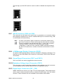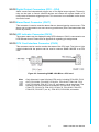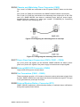
1
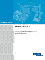
User Manual SNMP-1000-B2 Intelligent SNMP/HTTP Remote System Manager Copyright The documentation and the software included with this product are copyrighted 2015 by Advantech Co., Ltd. All rights are reserved. Advantech Co., Ltd. reserves the right to improve the products described in this manual at any time without notice. No part of this manual may be reproduced, copied, translated or transmitted in any form or by any means without the prior written permission of Advantech Co., Ltd. Information provided in this manual is intended to be accurate and reliable. However, Advantech Co., Ltd. assumes no responsibility for its use, nor for any infringements of the rights of third parties that may result from its use. Acknowledgements Intel and Pentium are trademarks of Intel Corporation. Microsoft Windows and MS-DOS are registered trademarks of Microsoft Corp. All other product names or trademarks are properties of their respective owners. Product Warranty (2 years) Advantech warrants the original purchaser that all its products will be free from defects in materials and workmanship for two years from the date of purchase. This warranty does not apply to products that have been repaired or altered by persons other than repair personnel authorized by Advantech, or products that have been subject to misuse, abuse, accident, or improper installation. Advantech assumes no liability under the terms of this warranty as a consequence of such events. Because of Advantech’s high quality-control standards and rigorous testing, most customers never need to use our repair service. If an Advantech product is defective, it will be repaired or replaced at no charge during the warranty period. For out-of-warranty repairs, customers are billed according to the cost of replacement materials, service time, and freight. Please consult your dealer for more details. If you suspect your product to be defective, follow the steps outlined below. 1. Collect all information about the problem encountered (for example, CPU speed, Advantech products used, other hardware and software used, etc.). Note anything abnormal and list any onscreen messages received when the problem occurs. 2. Call your dealer and describe the problem. Please have your manual, product, and any relevant information readily available. 3. If your product is diagnosed as defective, obtain an RMA (return merchandize authorization) number from your dealer. This allows us to process your return more quickly. 4. Carefully pack the defective product, a completed Repair and Replacement Order Card, and proof of purchase date (such as a photocopy of your sales receipt) in a shippable container. Products returned without a proof of purchase date are not eligible for warranty service. 5. Write the RMA number clearly on the outside of the package and ship the product prepaid to your dealer. SNMP-1000-B2 User Manual Part No. 20021000E1 Edition 2 Printed in Taiwan January 2015 ii Declaration of Conformity FCC Class A This equipment has been tested and found to comply with the limits for a Class A digital device, pursuant to part 15 of the FCC regulations. These limits are designed to provide reasonable protection against harmful interference when the equipment is operated in a commercial environment. This equipment generates, uses, and can radiate radio frequency energy and, if not installed and used in accordance with the instruction manual, may cause harmful interference to radio communications. Operation of this equipment in a residential area is likely to cause harmful interference, in such cases users are required to correct the interference at their own expense. This device complies with the requirements outline in part 15 of the FCC regulations. Operation is subject to the following two conditions: 1. This device may not cause harmful interference 2. This device must accept any interference received including interference that may cause undesired operation Caution! The battery is at risk of exploding if incorrectly replaced. The battery does not require charging. Replace only with Advantech-specified batteries. Message to the Customer Advantech customer services All Advantech products are built with the most exact specifications to ensure reliable performance in the harsh and demanding conditions typical of industrial environments. Whether your new Advantech device is destined for a laboratory or factory floor, be assured that your product will deliver the reliability and ease of operation for which Advantech is renowned. Your satisfaction is our primary concern. This is a guide to Advantech’s customer services. To ensure that you receive the full benefit of our services, please carefully follow the instructions below. Technical support We want customers to experience the maximum performance from our products. Thus, should you encounter technical difficulties, we are available to provide assistance. For the most frequently asked questions, answers are provided in the product documentation. These responses are typically more detailed than the advice provided over the phone; so please consult this manual first. If you still cannot find the answer, gather all the information or questions that apply to your problem, and with the product in hand, contact your dealer. Our dealers are well trained and ready to provide the support required to get the most from your Advantech products. In fact, most of the problems reported are minor and easily solved over the phone. Additionally, free technical support from Advantech engineers is available every business day. We are always ready to provide advice on application requirements or specific information regarding the installation and operation of any of our products. iii SNMP-1000-B2 User Manual Initial Inspection Before beginning card installation, please ensure that the materials specified in the packing list have been shipped. SNMP-1000-E1B2 One SNMP/HTTP system manager kernel board mounted on a PCI/ISA carrier board One 6-pin to 8-pin cable for CPU card connection One 2-pin cable for watchdog timer detection One ISA slot bracket Two thermal sensor board with cable sets One 9-pin to 9-pin modem cable One SNMP-1000-B2 startup manual One CD containing a utility program, SNMP MIB file, and user manual (in pdf format) SNMP-1000-E2B2 One SNMP/HTTP system manager kernel board mounted on a chassis carrier board One 6-pin to 8-pin cable for CPU card connection One 2-pin cable for watchdog timer detection One 9-pin to 12-pin serial port cable for COM2 of the CPU card One RJ-45 cable with bracket for an external LAN connection Two thermal sensor boards with cable sets One 9-pin to 9-pin modem cable One SNMP-1000-B2 startup manual One CD containing a utility program, SNMP MIB file, and user manual (in pdf format) SNMP-1000-LCD One message display module One 8-pin cable for SNMP-1000-B2 connection If any of the items listed above are missing or damaged, contact your distributor or sales representative immediately. The mechanical and electrical components of the product have been carefully inspected prior to shipping. The product should be free from marks and scratches and in perfect working order upon receipt. While unpacking, check the product for signs of shipping damage (for example, damaged packaging, scratches, dents, etc.). If your product is damaged or fails to meet specifications, notify our service department or your local sales representative immediately. Please also notify the carrier. Retain the shipping carton and packing material for inspection by the carrier. After inspection, we will make arrangements to repair or replace the unit. SNMP-1000-B2 User Manual iv Contents Chapter Chapter 1 Introduction..........................................1 1.1 1.2 Introduction ............................................................................................... 2 Specifications ............................................................................................ 3 1.2.1 Hardware Specifications ............................................................... 3 1.2.2 Dimensions ................................................................................... 3 1.2.3 Sensor Input Specifications .......................................................... 3 1.2.4 Firmware Specifications................................................................ 3 1.2.5 LCD Message Display Module with Keys ..................................... 4 1.2.6 Environmental Specifications........................................................ 4 2 Hardware Installation ..........................5 2.1 Kernel Module Installation......................................................................... 6 Figure 2.1 Kernel module and battery installation ....................... 6 Figure 2.2 Kernel module connectors.......................................... 6 Connecting Sensors and I/O Ports............................................................ 7 Figure 2.3 Extension board connectors ....................................... 7 Figure 2.4 Carrier board connectors............................................ 8 2.2.1 External Buzzer Connector (J1).................................................... 8 2.2.2 Bypass Password Protection (MJ1) .............................................. 8 2.2.3 External Power Connector (CN1) ................................................. 8 2.2.4 System SMBus Connector (CN3) ................................................. 8 2.2.5 10/100Base-T LAN Connectors (CN2 and CN5) .......................... 8 2.2.6 Temperature Sensor Connectors (CN4 and CN7)........................ 8 2.2.7 RS-232 Interface (CN8 and CN9) ............................................... 10 2.2.8 LCM Message Display Connector (CN10).................................. 10 2.2.9 Kernel Board Connectors (CN11 and CN12).............................. 10 2.2.10 Backplane Voltage Input Connector (CN13)............................... 10 2.2.11 Digital Input Connectors (DI1 ~ DI8) ........................................... 10 2.2.12 Digital Output Connectors (DO1 ~ DO4) .................................... 11 2.2.13 Alarm Reset Connector (CN17) .................................................. 11 2.2.14 LED Indicator Connector (CN18) ................................................ 11 2.2.15 CPU Card Interface Connector (CN19) ...................................... 11 Figure 2.5 Connecting SNMP-1000-B2 to a CPU card.............. 11 2.2.16 Chassis and Watchdog Timer Connector (CN20)....................... 12 Figure 2.6 Configuring the watchdog timer to interrupt.............. 12 Figure 2.7 Configuring the watchdog timer to reset................... 12 2.2.17 Power Good Input Connectors (CN16, CN21 ~ CN24) .............. 12 2.2.18 External HDD LED Connector (CN26)........................................ 12 2.2.19 Fan Connectors (FAN1 ~ FAN9) ................................................ 12 2.2.20 External Backup Battery Connector (BT1).................................. 12 2.2 Chapter 3 Getting Started...................................13 3.1 3.2 Configuring SNMP-1000-B2.................................................................... 14 Configuration Via the Serial Port............................................................. 14 3.2.1 Agent Configuration .................................................................... 15 Communication Over Ethernet................................................................ 21 3.3.1 Configuration Using Telnet ......................................................... 21 3.3.2 Configuration Using a Web Browser........................................... 21 3.3.3 Remote Access Via a Telephone Line........................................ 21 3.3.4 Setup Using the LCD Message Display Module ......................... 21 Table 3.1: LCD Display Module Function Keys ......................... 22 3.3 v SNMP-1000-B2 User Manual 3.4 3.3.5 Main Menu .................................................................................. 22 3.3.6 Agent Configuration .................................................................... 23 3.3.7 Setting the IP Address ................................................................ 23 3.3.8 Enable/Disable the BOOTP/HDCP Function .............................. 24 3.3.9 Agent Information ....................................................................... 24 3.3.10 Set System Date......................................................................... 25 3.3.11 Set System Time ........................................................................ 25 3.3.12 View Active Alarms ..................................................................... 25 3.3.13 View System Status.................................................................... 26 3.3.14 View Fan Speed ......................................................................... 27 3.3.15 View Temperature Status ........................................................... 27 3.3.16 View Watchdog Timer Status ..................................................... 27 3.3.17 View Voltage Status.................................................................... 28 3.3.18 View Power Supply Status.......................................................... 29 3.3.19 View Digital Input Status............................................................. 29 View CPU Card/Motherboard Status ...................................................... 30 4 Programming SNMP-1000-B2 .......... 31 4.1 4.2 4.3 4.4 4.5 Introduction ............................................................................................. 32 Entering the Pass Through Command Mode.......................................... 32 Command and Response Syntax ........................................................... 33 List of Device Codes and Subcodes ....................................................... 34 Summary of Command Set..................................................................... 35 4.5.1 Fan Read .................................................................................... 35 4.5.2 Temperature ............................................................................... 36 4.5.3 Voltage........................................................................................ 38 4.5.4 CPU Card ................................................................................... 40 4.5.5 Digital Input................................................................................. 45 4.5.6 WDT............................................................................................ 46 Appendix A Connector Pin Assignments............ 47 A.1 A.2 A.3 A.4 A.5 A.6 A.7 A.8 A.9 A.10 A.11 A.12 A.13 A.14 A.15 A.16 A.17 A.18 A.19 External Buzzer Connector (J1).............................................................. 48 Bypass Password Protection (MJ1) ........................................................ 48 External Power Connector (CN1) ........................................................... 48 10/100Base-T LAN Connector (CN2) ..................................................... 48 System SMBus Connector (CN3) ........................................................... 49 Temperature Sensor Connectors (CN4 and CN7).................................. 49 RS-232 Connector (CN8)........................................................................ 49 LCM Message Display Connector (CN10).............................................. 50 Kernel Board Connector (CN11)............................................................. 50 Kernel Board Connector (CN12)............................................................. 51 Backplane Voltage Input Connector (CN13)........................................... 51 Digital Input Connectors (DI1 ~ DI8) (CN14) .......................................... 52 Digital Output Connectors (DO1 ~ DO4) (CN15) .................................... 52 Alarm Reset Connector (CN17) .............................................................. 52 LED Indicator Connector (CN18) ............................................................ 53 CPU Card Interface Connector (CN19) .................................................. 53 Chassis and Watchdog Timer Connector (CN20)................................... 54 Power Good Input Connectors (CN16, CN21 ~ CN24)........................... 54 FAN Connectors (FAN1 ~ FAN9)............................................................ 54 Chapter SNMP-1000-B2 User Manual vi Chapter 1 Introduction 1 1.1 Introduction The SNMP-1000-B2 is a platform-independent server and PC system management controller that can detect the system operating conditions and notify users to take necessary action to avert system failure. The SNMP-1000-B2 is web enabled and supports multiple communication protocols. This server provides a simple tool for managing several remote servers and delivers reliability for critical applications such as computer telephony. Powerful and Easy to Use SNMP-1000-B2 can identify and measure numerous internal conditions, including system temperature, voltage, fan rotation, power supply, and CPU operations such as watchdog timer output. With the I2C interface, SNMP-1000-B2 can be used to monitor CPU temperature and voltages of Advantech's full-sized CPU cards. Depending on the event severity and user setup, the server generates different alarm outputs for SNMP traps, e-mails, pager messages, acoustic signals, system reset functions, and digital signal outputs. With the easy-to-use web-based interface, users can set the alarm criteria and outputs for all event triggers. The backup battery ensures that the SNMP-1000-B2 alarm function continues to operate even during total system power failures. Web Enabled, No Driver Needed Equipped with an onboard 10/100 Mbps Ethernet adapter, the SNMP-1000-B2 can be connected to existing networks. SNMP-1000-B2 also supports multiple network protocols, such as TCPIIP, SNMP, HTTP and Telnet, facilitating system management via a web browser. Because the device operates independently, no software drivers are required, which eliminates compatibility issues regarding different operating systems. Online Upgrades and Batch Setup The device firmware can be upgraded online using the setup utility. This eliminates the need to disassemble the chassis and collect each SNMP-1000-B2 module to conduct a firmware upgrade. The setup utility also supports the "batch setup" function, which allows users to save and duplicate a configuration to other modules. This freduces the time required to setup several SNMP-1000-B2 modules. Flexible Modular Hardware Design With its modular design, the SNMP-1000-B2 can be easily customized to suit any application. The ultra compact kernel module is only 40.5 mm wide and 93 mm long, and can be mounted on standard or customized carrier boards to meet different I/O extension requirements. The compact size ensures that the SNMP-1000-B2 module can be integrated into a wide range of customers’ systems. SNMP-1000-B2 User Manual 2 1.2.1 Hardware Specifications 20 MHz 80188-compatible CPU 512KB of Flash ROM and 512KB of SRAM One 10/100 Mbps onboard Ethernet adapter One RS-232 serial port with a 9600 baud rate One SM bus interface for PC system healthy status monitoring One SM bus interface for up to eight external temperature sensors Nine fan tachometer inputs (seven for SNMP-1000-E2B2) One onboard temperature sensor One LCM message display interface System watchdog time-out signal detector Four good power signals (one for SNMP-1000-E2B2) Eight digital inputs (SNMP-1000-E1B2 only) Four digital outputs (one for SNMP-1000-E2B2) Buzzer support 1.2.2 Dimensions Kernel module: 40.5 x 93 mm PCI/ISA carrier module: 175 x 107 mm Chassis carrier board: 55 x 115 mm 1.2.3 Sensor Input Specifications Voltage inputs: +5 V DC, -5 V DC, 5 V SB, +3.3 V DC, +12 V DC, -12 V DC Temperature sensors: LM75 digital temperature sensor, I2C interface, -30 ~ 125 °C (-22 ~ 257 °F) Fan speed monitor: Up to nine fans, 700 ~ 10000 RPM Power good/Digital input: High: > 2.4 VDC Low: < 0.8 VDC 1.2.4 Firmware Specifications System Status Monitoring and Management Real-time health status monitoring; provides a real-time status display in HTTP Java graphical format Supports history log graphical display and data downloads Alarm event log Alarm Notification Supports up to four e-mail addresses Alarm messages can be transmitted to optional LCD display modules SNMP trap: can notify up to eight SNMP administrators Pager notification: can send messages to up to eight pagers via an external modem Audible alarm sound Supported Protocols TCP, UDP, IP, ICMP, DHCP, BOOTP, ARP, SNMP, HTTP, and Telnet 3 SNMP-1000-B2 User Manual Introduction Chapter 1 1.2 Specifications Management Function Supports web-based remote configuration, control, and monitoring Remote reset, power OFF/ON Remote digital output signal control Remote message display control Firmware upgrade via serial port and Ethernet port Modem dial in (console mode only) 1.2.5 LCD Message Display Module with Keys LCD module with backlight supports displays of up to 2 rows and 16 characters Module is 147 (W) x 42 (H) x 158 mm (L), fits into a 5.25" drive bay, and can accomodate a 3.5" HDD Features five keys: up, down, enter, escape, and alarm sound off Optional Backup Battery: Charge time: 3 hours Battery type: Li-ion Battery capacity: 1800 mA*h (fully charged, for 45 ~ 50 minutes operation, dependent on the output used) Battery life: 1 year @ 20 °C, 80% capacity after 500 cycles of charge and discharge Power Consumption 5 V @ 550 mA 1.2.6 Environmental Specifications Storage temperature: -20 ~ 70 °C (4 ~ 158 °F) Operating temperature: 0 ~ 60 °C (32 ~ 140 °F) Relative humidity: 5 ~ 95% RH non-condensing SNMP-1000-B2 User Manual 4 Chapter 2 2 Hardware Installation 2.1 Kernel Module Installation The SNMP-1000-B2 modular design facilitates I/O connection. The kernel module can be mounted on an I/O extension/carrier module. Several extension modules designed for specific application needs are available on the market. If your extension module differs from that depicted in this section, please refer to the user manual of your extension module for information. The kernel module features two 32-pin connectors labeled MCN1 and MCN2. The extension module features two 32-pin connectors labeled CN11 and CN12. MCN1 of the kernel module should be mounted onto CN11 of the extension module, and MCN2 of the kernel module should be mounted onto CN12 of the extension module. Once mounted, secure the kernel module to the extension module using the provided studs and screws. Figure 2.1 Kernel module and battery installation Figure 2.2 Kernel module connectors SNMP-1000-B2 User Manual 6 This section illustrates how to connect sensors and I/O ports using a PCI/ISA fullfunction extension board as an example. Your extension board may not have all the I/ O functions of this board. The PCI/ISA extension module is designed with an ISA edge and a PCI edge. This module can be inserted into an ISA bus slot or a PCI bus slot to detect the bus voltages. However, because SNMP-1000-B2 does not communicate with the system through the ISA or PCI bus, no driver is required. Figure 2.3 Extension board connectors 7 SNMP-1000-B2 User Manual Hardware Installation 2.2 Connecting Sensors and I/O Ports Chapter 2 MJ1: Restores the default username and password and should be used to reset the system settings when users forget their username and password. Otherwise, MJ1 should be left open under normal operation. Operation procedure: 1. Power off the SNMP-1000-B2 and remove the backup battery. 2. Short MJ1 using a jumper 3. Power on the SNMP-1000-B2 and wait until the system is operable 4. Turn the system power off 5. Remove MJ1. The username and password are reset to "advantech" and "admin" MCN1 and MCH2: Sensor and I/O interface (Please refer to Appendix A for pin assignments) Figure 2.4 Carrier board connectors 2.2.1 External Buzzer Connector (J1) Supports connection to an external buzzer. 2.2.2 Bypass Password Protection (MJ1) Restores the default alarm board ID and password. 2.2.3 External Power Connector (CN1) This connector is used to provide auxiliary power to SNMP-1000-B2. This connector is only required when an extension board is not plugged into the PCI or ISA slots. 2.2.4 System SMBus Connector (CN3) Enables users to read system SMBus signals. 2.2.5 10/100Base-T LAN Connectors (CN2 and CN5) CN5 is a standard RJ-45 connector for Ethernet connectivity. A box header (CN2) is also available for internal connectivity. The chassis carrier board is equipped with a special cable (P/N 1703120900) that features a box header at one end and an RJ-45 at the other end. An adaptor bracket allows users to fix the RJ-45 end to the chassis via an existing DB-9 COM port. 2.2.6 Temperature Sensor Connectors (CN4 and CN7) These connectors interface with LM75 digital temperature sensors via SM bus. SNMP-1000-B2 supports monitoring of up to nine temperatures. One sensor located on the kernel module is designated as Temp. 0, and up to eight external sensors can be connected. External temperature sensors and cables are available from Advantech. Sensors can be connected in series in any order to either connectors, but each sensor must be allocated a unique ID ranging from 1 ~ 8 using the DIP switch on the sensor board. SNMP-1000-B2 User Manual 8 1-3 of DIP switch Off Off Off Temp. 2 Off Off On Temp. 3 Off On Off Temp. 4 Off On On Temp. 5 On Off Off Temp. 6 On Off On Temp. 7 On On Off Temp. 8 On On On 9 SNMP-1000-B2 User Manual Hardware Installation Temp. 1 Chapter 2 Sensor ID The last digit (4) of the DIP switch is used to enable or disable the temperature sensor. Enable Disable 2.2.7 RS-232 Interface (CN8 and CN9) The serial port can be used as a console port or connected to an external modem that supports a telephone line. CN9 is a standard DB-9 port for external wiring; CN8 is a box header for internal wiring. Note A unique “null modem” cable is required to connect the module serial port to a PC serial port. Please ensure that the cable features reversed Tx and Rx signals at one end and only Pins 2, 3, and 5 are connected. This type of cable is available from Advantech (part number 1700091801). If other pins are connected, SNMP-1000-B2 will identify the RS-232 connection as a modem connection and terminate it immediately. 2.2.8 LCM Message Display Connector (CN10) An optional LCM message display module is available for displaying messages. The input key on the LCM module can be used for on-site setup. CN10 is the LCM module interface. 2.2.9 Kernel Board Connectors (CN11 and CN12) CN11 and CN12 are used to piggyback the kernel module. 2.2.10 Backplane Voltage Input Connector (CN13) This connector is used for detecting voltages on the backplane. An 8-pin connector on the backplane can be directly cabled to CN13 to simplify the wiring. 2.2.11 Digital Input Connectors (DI1 ~ DI8) SNMP-1000-B2 can monitor up to eight TTL-level digital signals. These digital inputs can be used to detect external devices or identify a health status, such as chassis intrusion. These connectors are not available for the chassis carrier board. SNMP-1000-B2 User Manual 10 Alarm events can independently trigger one of four digital output signals. These signals can be used to control external devices and restore the system health or to notify users of the alarm-triggering event. This connector is not available on the chassis carrier board. 2.2.13 Alarm Reset Connector (CN17) 2.2.14 LED Indicator Connector (CN18) The system status can be displayed using LED indicators. CN18 is connected to an LED indicator board. Please refer to Appendix A regarding pin assignments. 2.2.15 CPU Card Interface Connector (CN19) This connector can be used to monitor the status of the CPU card. The 8 pin to 6 pin cable included with the product can be used to connect SNMP-1000-B2 to a CPU card. Figure 2.5 Connecting SNMP-1000-B2 to a CPU card Note Only Advantech’s new full-sized CPU cards, including PCA-6002, PCA6003, PCA-6004, PCA-6005, PCA-6181, PCA-6183, PCA-6184, PCA6185, PCA-6186, PCA-6277 (rev. B), and newer, can be monitored. The following CPU cards cannot be monitored: PCA-6155V, PCA-6168, PCA-6175, PCA-6176, PCA-6178, PCA-6179, PCA-6180, PCA-6275, PCA-6276, PCA-6277 (rev. A), PCA-6278, PCA-6359, and earlier. 11 SNMP-1000-B2 User Manual Hardware Installation This connector is used to reset the alarm after an alarm-triggering event occurs. The alarm can be connected to an auto-recovery push button (that is activated when the button is pushed). Chapter 2 2.2.12 Digital Output Connectors (DO1 ~ DO4) 2.2.16 Chassis and Watchdog Timer Connector (CN20) Pins 1 and 2 of CN20 are connected to the ATX power ON/OFF button on the chassis. Pins 3 and 4 of CN20 are connected to the SNMP-1000-B2 chassis reset button. Pins 5 and 6 of CN20 are connected to the watchdog timer output pins of the CPU card (J2). SNMP-1000-B2 can detect a watchdog timer time-out output signal. Included with the product is a cable (part number 1703020558) for connecting SNMP-1000-B2 to the watchdog timer. Figure 2.6 Configuring the watchdog timer to interrupt Figure 2.7 Configuring the watchdog timer to reset 2.2.17 Power Good Input Connectors (CN16, CN21 ~ CN24) Up to four power fail signals can be detected. SNMP-1000-B2 can detect “power good” and “power fail” signals if the power supply unit emits these output signals. 2.2.18 External HDD LED Connector (CN26) Output HDD LED signal to chassis bezel. 2.2.19 Fan Connectors (FAN1 ~ FAN9) These connectors provide +12 V power to fans and receive tachometer signals from the fans. SNMP-1000-B2 can only detect fans that emit tachometer signals. This type of fan generates two pulses per revolution. 2.2.20 External Backup Battery Connector (BT1) SNMP-1000-B2 supports an external backup battery to maintain alarm notifications during total system power failures. SNMP-1000-B2 User Manual 12 Chapter 3 Getting Started 3 3.1 Configuring SNMP-1000-B2 The SNMP-1000-B2 HTTP intelligent system manager must be configured prior to use. Configuration can be conducted through a PC serial port using terminal emulator software, such as HyperTerminal in Windows 98/NT, or via the Ethernet port using Telnet or a browser such as Chrome or Internet Explorer. For security reasons, certain parameters can only be configured via the serial port. The setup utility software can be found on the utility CD shipped with SNMP-1000B2. This can assist system managers with setting up multiple SNMP-1000-B2 systems with the same configuration. A specific configuration can be saved to a file and then copied to other modules. Before configuration, users must install and power up their SNMP-1000-B2 module. Please refer to Chapter 2 for installation instructions. SNMP-1000-B2 can be connected to a network via the LAN port, or via the serial port connected to the serial port of a PC. For security reasons, the administrator name and password can only be changed via the serial port directly connected to a PC. Note A unique “null modem” cable is required to connect the module serial port to a PC serial port. Please ensure that the cable features reversed Tx and Rx signals at one end and only Pins 2, 3, and 5 are connected. This type of cable is available from Advantech (part number 1700091801). If other pins are connected, SNMP-1000-B2 will identify the RS-232 connection as a modem connection and terminate it immediately. When all cables are connected, SNMP-1000-B2 can be powered up. A green LED on the kernel module indicates that 5 V of power is being supplied to SNMP-1000-B2. The system initiates a self-testing procedure that takes approximately 5 seconds to complete before the system can be used. 3.2 Configuration Via the Serial Port In this manual, HyperTerminal for Windows (95, 98, Me, NT, 2000, or XP) is used as an example to demonstrate the configuration process. 1. Start HyperTerminal by accessing the “Accessories” program group. 2. Enter a name and choose an icon for the connection. 3. In the “Connect using” box, select “Direct to COMx”. Here x represents the number of the COM port connected to SNMP-1000-B2. 4. Configure your PC serial port to 9600 bps, 8 data bits, no parity, 1 stop bit with no flow control. 5. After users press “Enter”, the SNMP-1000-B2 prompts for the administrator name and password. The default administrator name is “advantech” and the default password is “admin”. Note Access through Telnet or via a serial port is only permitted using the "Admin User Name" and "Admin User Password" set in the Control Group. SNMP-1000-B2 User Manual 14 Chapter 3 3.2.1 Agent Configuration Select "1" to access the Agent Configuration function. 3.2.1.1 Agent Group The following items can be set under this command: SNMP Agent Model Name: The SNMP controller model name. The default value is SNMP-1000-B2. We recommend not changing the default model name. IP Address: The IP address of SNMP-1000-B2. Gateway Address: The network default gateway address. Network Mask: The sub-net mask setting. SNMP Agent Date: The internal date of SNMP-1000-B2. Format: mm/dd/yyyy SNMP Agent Time: The internal time of SNMP-1000-B2. Format: hh:mm:ss Enter the number of the field you desire to alter and follow the instructions to input a new value. 15 SNMP-1000-B2 User Manual Getting Started After entering a password, users can select one of items listed in the image below. 3.2.1.2 Control Group The following items can be set under this command: Admin User Name: The SNMP-1000-B2 administrator user name. Only the administrator is permitted to input the console mode. The default admin user name is “advantech”. Admin User Password: The administrator password. This password enables users to read and write to SNMP-1000-B2. The default admin user password is “admin”. Community Read-Only: A general password for read-only access. The default read-only password is “public”. BOOTP/DHCP Control: Enables/disables the BOOTP/DHCP protocol. Telnet Control: Enables/disables the Telnet protocol. TFTP Upgrade Control: Enables/disables the TFTP protocol for firmware upgrades through local networks. HTTP Security Control: Enables/disables HTTP login password requests. SNMP-1000-B2 User Manual 16 17 SNMP-1000-B2 User Manual Getting Started 3.2.1.4 Access Control Table This table allows users to restrict SNMP-1000-B2 access from specific IP addresses. Users can add IP addresses and set the access control. The configuration options are NoAccess, Read Only, and Read/Write. Workstations cannot display information if their IP address is set to “NoAccess”. Press “1” to modify a line in the table. Press “2” to delete a line of data. This table is used for access via SNMP and HTTP. Access through Telnet or a serial port is only permitted using the “Admin User Name” and “Admin User Password” in the Control Group. Chapter 3 3.2.1.3 Parameter Group The following items can be set under this command: sysDescription: A description of this system. This is an alphanumeric string of up to 31 bytes. The default value is empty. sysContact: The contact information of the entity managing the system. This is an alphanumeric string of up to 15 bytes. The default value is empty. sysName: The name of this system. This is an alphanumeric string of up to 15 bytes. The default name is “Advantech”. sysLocation: The location of this system. This is an alphanumeric string of up to 15 bytes. The default value is empty. 3.2.1.5 Trap Receiver Table SNMP-1000-B2 can be managed with SNMP-compatible software from a remote server connected to a network. The IP addresses of SNMP trap receivers can be added to the list if SNMP-compatible management software is available at the addresses. Press “1” to modify a line in the table. Press “2” to delete a line of data. The Severity Level allows users to specify the alarm level. Traps are not sent if the alarm severity is lower than the specified level. 3.2.1.6 E-mail Notification Menu SNMP-1000-B2 can send e-mails to specified e-mail addresses every day at a fixed time or after an alarm-triggering event. From this menu, users can configure the following items: DNS Address: The IP address of the network domain name server in dotted format. Mail Server: The IP address of the mail server in dotted format. SNMP-1000-B2 User Manual 18 Chapter 3 Mail Status Daily: Option 5 allows users to specify the time when the SNMP1000-B2 sends daily logs via e-mail to pre-specified accounts. Mail Receivers Table: Option 6 allows users to specify the receiving e-mail addresses. 19 SNMP-1000-B2 User Manual Getting Started Mail Account: The account name used for logging SNMP-1000-B2 into the mail server. Mail Conditions: This function allows users to specify the conditions for sending an email. The choices include Alarm: Send an e-mail when an alarm-triggering event occurs. Daily Logs: Send daily logs at a specified time. Alarm and Log: Send both alarm-triggered notifications and daily logs. Alarm Level: This allows users to set the alarm severity for triggering an alarm notification. This item is useful when the Mail Condition is set to “Alarm” or “Alarm and Log”. Status: This allows users to set the status of an e-mail address. The status can be set to Disabled when the address is temporarily not in use. SNMP-1000-B2 User Manual 20 3.3.1 Configuration Using Telnet Configuration using Telnet is basically the same as that via the serial port. First, ensure that your computer has a TCP/IP network and web browser installed. In the address line type “xxx.xxx.xxx.xxx”, with “xxx.xxx.xxx.xxx” being the IP address of SNMP-1000-B2. The SNMP-1000-B2 then prompts users to enter a user name and password, which is the same as described in Section 3.2. 3.3.2 Configuration Using a Web Browser The easiest way to configure SNMP-1000-B2 is by using a web browser. Input the URL “http://xxx.xxx.xxx.xxx”, with “xxx.xxx.xxx.xxx” being the IP address of SNMP1000-B2. The SNMP-1000-B2 then prompts users to enter a user name and password. 3.3.3 Remote Access Via a Telephone Line SNMP-1000-B2’s command mode can be accessed remotely via a telephone line. The SNMP-1000-B2 module and your PC must be connected to a telephone line through a modem. HyperTerminal for Windows or other dialing software tools can be used for this purpose. Please refer to the user manual of your dialing program for setup instructions. 3.3.4 Setup Using the LCD Message Display Module The LCD message display module is equipped with five buttons. The module can be used for on-site service without a network-connected PC. The up (↑) and down (↓) arrow keys on the LCD display panel allow users to scroll through the configuration setup menu. The icon provides the functions “enter” or “OK”, and the ESC icon provides the functions “escape” or “cancel”. When users alter settings and/or wish to access a lower menu level, they must press “ENTER” to confirm the changes. If users press “ESC”, the system return to a higher menu level without saving any changes. When an alarm notification is triggered and warning sounds are emitted, users can press the alarm reset button audible alarm sounds. 21 to stop the SNMP-1000-B2 User Manual Getting Started To communicate with SNMP-1000-B2 over Ethernet, a computer equipped with an Ethernet and TCP/IP network is required. Users must obtain the IP address of the SNMP-1000-B2 module to communicate with it over Ethernet. There are four methods for determining an IP address. A. The default IP address is 172.20.x.x, where x.x is the last four digits of the Ethernet MAC address. The MAC address is provided on the kernel module. For example, if the MAC address is 00 E0 d8 03 15 36 (hexadecimal), the IP address is 172.20.21.54. B. The IP address can be determined in the console mode, as described in Section 3.2.1.1 under "Agent Configuration". C. The IP address can be obtained using the LCM display if your SNMP-1000-B2 device is connected to the LCM display module. D. All SNMP-1000-B2 modules connected to the same network can be identified using the setup utility. Chapter 3 3.3 Communication Over Ethernet Table 3.1: LCD Display Module Function Keys Keys Function Scroll Up Scroll Down Enter ESC ESC Escape Alarm Reset Flowcharts for each function are presented in the following sections. Please note that not all settings can be accessed via the LCD module. Certain parameters can only be set under the command mode or via the web page. 3.3.5 Main Menu SNMP-1000-B2 User Manual 22 Chapter 3 3.3.6 Agent Configuration Getting Started 3.3.7 Setting the IP Address 23 SNMP-1000-B2 User Manual 3.3.8 Enable/Disable the BOOTP/HDCP Function 3.3.9 Agent Information ↑ Enter Main Menu Agent Info Enter Model Name SNMP-1000-B1 ESC ↓ ↑ Enter F/W Version V2.xx ESC ↓ ↑ Enter System Date 01/31/2001 ESC ↓ ↑ Enter System Time 13:00 ESC ↓ ↑ Enter System Up Time 9999Day 14:25:30 ESC ↓ SNMP-1000-B2 User Manual 24 Chapter 3 3.3.10 Set System Date Getting Started 3.3.11 Set System Time 3.3.12 View Active Alarms 25 SNMP-1000-B2 User Manual 3.3.13 View System Status SNMP-1000-B2 User Manual 26 Chapter 3 3.3.14 View Fan Speed Getting Started 3.3.15 View Temperature Status 3.3.16 View Watchdog Timer Status 27 SNMP-1000-B2 User Manual 3.3.17 View Voltage Status SNMP-1000-B2 User Manual 28 Chapter 3 3.3.18 View Power Supply Status Getting Started 3.3.19 View Digital Input Status 29 SNMP-1000-B2 User Manual 3.4 View CPU Card/Motherboard Status SNMP-1000-B2 User Manual 30 Chapter 4 4 Programming SNMP1000-B2 4.1 Introduction SNMP-1000-B2 can be accessed and controlled by direct command inputs. With this function, SNMP-1000-B2 can be easily controlled and integrated into a user’s system via the appropriate user program. 4.2 Entering the Pass Through Command Mode Before programming SNMP-1000-B2, users must connect the host computer to SNMP-1000-B2 via the serial port or Telnet. Follow the steps outlined below to enter the Pass Through Command mode. 1. Power on SNMP-1000-B2 to allow the device to send the identifying string "\nAdvantech v2.xx (SNxxxxxx) Ready \n" to the host computer via a COM port. 2. On the host computer side, send a carriage return (enter, or \r). 3. SNMP-1000-B2 then responds by sending the main menu title and a message requesting that the user name be entered. "\n\n +==============================================+ |[ SNMP Agent Configuration Utility Main Menu ] | +==============================================+ \n Enter User Name:" 4. On the host computer side, send the user name \r. SNMP-1000-B2 will respond with the user name \n\n and request that the password be entered. Host computer sends: "advantech\r" SNMP-1000-B2 responds: "advantech\n\n Enter Password:" 5. On the host computer side send the password \r. SNMP-1000-B2 will respond with the password \n\n\n and access to the main menu. EX. Host computer side sends: "admin\r" SNMP-1000-B2 responds: "*****\n\n +==============================================+ |[ SNMP Agent Configuration Utility Main Menu ]| +==============================================+ 1. Agent Configuration 2. Remote Control 3. Restart Agent 4. Reset Configuration To Default 5. Access Agent Command 0. Exit SNMP-1000-B2 User Manual 32 6. 4.3 Command and Response Syntax The format of commands and responses is displayed as follows: a. Write command: w!!&xxx b. Read command: r!!& c. Response: [repeat received command]\n Response: xxx\n Command: w: write command r: read command !!: device code &: device subcode xxx: value in ASCII code; this can be "Done" or "Invalid" in the SNMP-1000-B2 response. Examples: 1. Write lower limit of Fan 0 to "1000" rpm EX. Host computer side sends: "w1011000\r" SNMP-1000-B2 responds: "w1011000\n Response: Done\n Command:" 2. Read lower limit of Fan 0 EX. Host computer side sends: "r101\r" SNMP-1000-B2 responds: "r101\n Response: 1000\n Command:" 3. If the input command is incorrect then SNMP-1000-B2 will respond with an invalid message notification. EX. Host computer side sends: "r905\r" Here the device subcode is over range. SNMP-1000-B2 responds: "r905\n Response: Invalid\n Command:" 33 SNMP-1000-B2 User Manual Programming SNMP-1000-B2 On the host computer side send 5\r. SNMP-1000-B2 will respond 5\n\n and enter the pass through command mode. Host computer side sends: "5\r" SNMP-1000-B2 responds: "5\n Command :" Once the pass through command mode is entered, SNMP-1000-B2 is ready to receive commands. Chapter 4 Please Enter Your Choice => " 4.4 List of Device Codes and Subcodes Device Codes Code 10 11 12 13 14 15 16 17 18 Device Fan 0 Fan 1 Fan 2 Fan 3 Fan 4 Fan 5 Fan 6 Fan 7 Fan 8 Code 20 21 22 23 24 25 26 27 28 Device Temp 0 Temp 1 Temp 2 Temp 3 Temp 4 Temp 5 Temp 6 Temp 7 Temp 8 Code 30 31 32 33 34 35 36 37 38 Device 33V 5V -5 V 5 Vsb 12 V -12 V Code 40 41 Device CPU Fan1 CPU Fan2 Code 50 51 Device CPU Temp CPU Temp Code 60 61 62 63 64 65 66 67 68 Device CPU 1 CPU 2 Vcore VI/O 5V -5 V 12 V -12 V Code 70 71 72 73 Device Power 0 Power 1 Power 2 Power 3 Code 80 81 82 83 84 85 86 87 Device DI 0 DI 1 DI 2 DI 3 DI 4 DI 5 DI 6 DI 7 Code 90 Device WDT SNMP-1000-B2 User Manual 34 1 2 3 4 Fan Lower Limit Upper Limit Event Out High Event Current Speed Temp Alarm Level High Alarm Lower Limit Low Alarm Low Event Current Level Output Temp Upper Limit Normal Level Normal Level Alarm Level Lower Limit Alarm Level Alarm Level Event Output Alarm Level Event Output Event Output Current Status Event Out Current Status Current Status Current Voltage Voltage Power DI WDT 5 6 7 4.5 Summary of Command Set 4.5.1 Fan Read Command Device Device Code r101 Fan 0 10 r111 Fan 1 11 r181 Fan 8 18 r102 Fan 0 10 r112 Fan 1 11 r182 Fan 8 18 r103 Fan 0 10 r113 Fan 1 11 r183 Fan 8 18 r104 Fan 0 10 r114 Fan 1 11 r184 Fan 8 18 35 Device Sub-Item Device Subcode Lower Limit 1 Alarm Level 2 Event Output 3 Current Speed 4 SNMP-1000-B2 User Manual Programming SNMP-1000-B2 Device Code Chapter 4 Device Subcodes Command Device Device Code w101xxxx Fan 0 10 w111xxxx Fan 1 11 w181xxxx Fan 8 18 w102x Fan 0 10 w112x Fan 1 11 Device Sub-Item Device Subcode Lower Limit 1 Alarm Level 2 Value (xxxx) Remark 1000 9999 RPM in ASCII code 1 Not Used 2 No Alarm 3 Critical w172x Fan 7 17 4 Major w182x Fan 8 18 5 Minor w103x Fan 0 10 1 None w113x Fan 1 11 2 Power Off w163x Fan 6 16 w173x Fan 7 w183x Fan 8 3 DO 0 4 DO 1 17 5 DO 2 18 6 DO 3 Event Output 3 4.5.2 Temperature Command Device Device Code r201 Temp 0 20 r211 Temp 1 21 r281 Temp 8 28 r202 Temp 0 20 r212 Temp 1 21 r282 Temp 8 28 r203 Temp 0 20 r213 Temp 1 21 r283 Temp 8 28 r204 Temp 0 20 r214 Temp 1 21 r284 Temp 8 28 r205 Temp 0 20 r215 Temp 1 21 r285 Temp 8 28 SNMP-1000-B2 User Manual 36 Device Sub-Item Device Subcode Upper Limit 1 High Alarm Level 2 High Event Output 3 Lower Limit 4 Low Alarm Level 5 20 r216 Temp 1 21 r286 Temp 8 28 r207 Temp 0 20 r217 Temp 1 21 r287 Temp 8 28 Command Device Device Code w201xxxxx Temp 0 20 w211xxxxx Temp 1 21 Device Sub-Item Low Event Output 6 Current Temp 7 Device Subcode Upper Limit 1 w281xxxxx Temp 8 28 w202x Temp 0 20 w212x Temp 1 21 Value (xxxx) Remark Temperature value in ASCII, ° C, or °F 55 ~ 125 (° C) according to or the -67 ~ 257 (° F) system setting, max. 5 characters, incl. "-", "." 1 High Alarm 2 Level Not Used 2 No Alarm 3 Critical 4 Major w272x Temp 7 27 w282x Temp 8 28 5 Minor w203x Temp 0 20 1 None w213x Temp 1 21 2 Power Off 3 DO 0 4 DO 1 High Event 3 Output w263x Temp 6 26 w273x Temp 7 27 5 DO 2 w283x Temp 8 28 6 DO 3 w204xxxxx Temp 0 20 w214xxxxx Temp 1 21 Temperature value in ASCII, ° C, or 55 ~ 125 (° C) ° F according to or -67 ~ 257 (° F) the system setting, max. 5 characters, incl. "-", "." Lower Limit 4 w284xxxxx Temp 8 28 w205x Temp 0 20 w215x Temp 1 21 w275x Temp 7 27 w285x Temp 8 28 Low Alarm Level 37 5 1 Not Used 2 No Alarm 3 Critical 4 Major 5 Minor SNMP-1000-B2 User Manual Programming SNMP-1000-B2 Temp 0 Chapter 4 r206 w206x Temp 0 20 1 None w216x Temp 1 21 2 Power Off 3 DO 0 4 DO 1 Low Event Output 6 w266x Temp 6 26 w276x Temp 7 27 5 DO 2 w286x Temp 8 28 6 DO 3 4.5.3 Voltage Command Device Device Code Device Sub-Item Device Subcode r301 3 3V 30 r311 5V 31 r321 -5V 32 r331 5VSB 33 r341 12V 34 r351 -12V 35 r302 3 3V 30 r312 5V 31 r322 -5V 32 r332 5VSB 33 r342 12V 34 r352 -12V 35 r303 3 3V 30 r313 5V 31 r323 -5V 32 r333 5VSB 33 r343 12V 34 r353 -12V 35 r304 3 3V 30 r314 5V 31 r324 -5V 32 r334 5VSB 33 r344 12V 34 r354 -12V 35 r305 3 3V 30 r315 5V 31 r325 -5V 32 r335 5VSB 33 r345 12V 34 r355 -12V 35 SNMP-1000-B2 User Manual 38 Upper Limit 1 Lower Limit 2 Alarm Level 3 Event Output 4 Current Voltage 5 Device Code Device Sub-Item Device Value(xxxx) Subcode w301xxxxxx 3 3V 30 w311xxxxxx 5V 31 w321xxxxxx -5V 32 w331xxxxxx 5VSB 33 w341xxxxxx 12V 34 w351xxxxxx -12V 35 w302xxxxxx 3 3V 30 w312xxxxxx 5V 31 w322xxxxxx -5V 32 w332xxxxxx 5VSB 33 w342xxxxxx 12V 34 w352xxxxxx -12V 35 w303x 3 3V 30 1 Not Used w313x 5V 31 2 No Alarm w323x -5V 32 w333x 5VSB 33 3 Critical w343x 12V 34 w353x -12V 35 4 Major w304x 3 3V 30 5 Minor w314x 5V 31 1 None w324x -5V 32 2 Power Off w334x 5VSB 33 3 DO 0 w344x 12V 34 4 DO 1 w354x -12V 35 5 DO 2 6 DO 3 Upper Limit 1 -15 0 15 0 Lower Limit 2 -15 0 15 0 Alarm Level Event Output 39 3 4 Remark Voltage value in ASCII code, max. 6 characters, incl. "", "." ex.: 03.53-12.5513 SNMP-1000-B2 User Manual Programming SNMP-1000-B2 Device Chapter 4 Command 4.5.4 CPU Card Command Device Device Code r401 CPU 1 40 r411 CPU 2 41 r402 CPU 1 40 r412 CPU 2 41 r403 CPU 1 40 r413 CPU 2 41 r404 CPU 1 40 r414 CPU 2 41 r501 CPU 1 50 r511 CPU 2 51 r502 CPU 1 50 r512 CPU 2 51 r503 CPU 1 50 r513 CPU 2 51 r504 CPU 1 50 r514 CPU 2 51 r505 CPU 1 50 r515 CPU 2 51 r506 CPU 1 50 r516 CPU 2 51 r507 CPU 1 50 r517 CPU 2 51 r601 CPU 1 60 r611 CPU 2 61 r621 CPU VI/O 62 r631 CPU card 63 r641 CPU card - 64 r651 CPU card 65 r661 CPU card - 66 r602 CPU 1 60 r612 CPU 2 61 r622 CPU VI/O 62 r632 CPU card 63 r642 CPU card - 64 r652 CPU card 65 r662 CPU card - 66 SNMP-1000-B2 User Manual 40 Device Sub-Item Device Subcode Lower Limit 1 Alarm Level 2 Event Output 3 Current Speed 4 Upper Limit 1 High Alarm Level 2 High Event Output 3 Lower Limit 4 Low Alarm Level 5 Low Event Output 6 Current Temp 7 Upper Limit 1 Lower Limit 2 60 r613 CPU 2 61 r623 CPU VI/O 62 r633 CPU card 63 r643 CPU card - 64 r653 CPU card 65 r663 CPU card - 66 r604 CPU 1 60 r614 CPU 2 61 r624 CPU VI/O 62 r634 CPU card 63 r644 CPU card - 64 r654 CPU card 65 r664 CPU card - 66 r605 CPU 1 60 r615 CPU 2 61 r625 CPU VI/O 62 r635 CPU card 63 r645 CPU card - 64 r655 CPU card 65 r665 CPU card - 66 Command Device Device Code w401xxxx CPU 1 40 w411xxxx CPU 2 41 w402x CPU 1 40 w412x CPU 2 Command Device w403x CPU 1 41 Device Code Device Sub-Item CPU 2 3 Event Output 4 Current Voltage 5 Device Subcode Value (xxxx) Remark 1000 9999 RPM in ASCII 1 Not Used 2 No Alarm 3 Critical 4 Major 5 Minor Value (xxxx) Remark 1 None 2 Power Off 3 DO 0 4 DO 1 5 DO 2 6 DO 3 Lower Limit 1 Alarm Level Device Sub-Item 2 Device Subcode 40 Event Output w413x Alarm Level 41 41 3 SNMP-1000-B2 User Manual Programming SNMP-1000-B2 CPU 1 Chapter 4 r603 Command Device Device Code w501xxxxx CPU 1 50 w511xxxxx w502x w512x w503x CPU 2 CPU 1 CPU 2 CPU 1 51 50 Device Sub-Item Upper Limit Device Subcode Value (xxxx) Remark 1 -55 ~ 125 (° C) or -67 ~ 257 (° F) Temperature value in ASCII, ° C, or ° F according to the system setting, max. 5 characters, incl. "-", "." 1 Not Used 2 No Alarm 3 Critical 4 Major 5 Minor 1 None 2 Power Off 3 DO 0 4 DO 1 5 DO 2 6 DO 3 Temperature value in ASCII, ° C, or ° F according to the system setting, max. 5 characters, incl. "-", "." High Alarm 2 Level 51 50 High Event 3 Output w513x w504xxxxx CPU 2 CPU 1 51 50 w514xxxxx CPU 2 51 Lower Limit 4 -55 ~ 125 (° C) or -67 ~ 257 (° F) Command Device Device Code Device Sub-Item Device Subcode Value (xxxx) Remark w505x CPU 1 50 w515x w506x CPU 2 CPU 1 51 Low Alarm 5 Level 50 High Event 6 Output w516x CPU 2 SNMP-1000-B2 User Manual 51 42 1 Not Used 2 No Alarm 3 Critical 4 Major 5 Minor 1 None 2 Power Off 3 DO 0 4 DO 1 5 DO 2 6 DO 3 w601xxxxxx w611xxxxxx w621xxxxxx w641xxxxxx w651xxxxxx w661xxxxxx w602xxxxxx w612xxxxxx w622xxxxxx CPU 1 Vcore CPU 2 Vcore CPU VI/O CPU card +5V CPU card -5V CPU card +12V CPU card -12V CPU 1 Vcore CPU 2 Vcore CPU VI/O w662xxxxxx CPU card +5V CPU card -5V CPU card +12V -12V Command Device w603x CPU 1 Vcore CPU 2 Vcore CPU VI/O w632xxxxxx w642xxxxxx w652xxxxxx w613x w623x w633x w643x w653x w663x CPU card +5V CPU card -5V CPU card +12V CPU card -12V Device Code Device Sub-Item Device Subcode Value (xxxx) Remark 60 61 62 63 Upper Limit 1 64 65 66 -15 ~ 15 60 Voltage value in ASCII code, max. 6 characters, incl. "-", "." 61 62 63 Lower Limit 2 64 65 66 Device Code Device Sub-Item Device Subcode Value (xxxx) Remark 60 1 Not Used 61 2 No Alarm 3 Critical 65 4 Major 66 5 Minor Alarm Level 43 3 SNMP-1000-B2 User Manual Programming SNMP-1000-B2 w631xxxxxx Device Chapter 4 Command w604x w614x w624x w634x w644x w654x w664x CPU 1 Vcore CPU 2 Vcore CPU VI/O CPU card +5V CPU card -5V CPU card +12V CPU card -12V 60 1 None 61 2 Power Off 3 DO 0 64 4 DO 1 65 5 DO 2 66 6 DO 3 62 Event Output 63 Command Device Device Code r701 Power 1 70 r711 Power 2 71 r721 Power 3 72 r731 Power 4 73 Command Device Device Code r702 Power 1 70 r712 Power 2 71 r722 Power 3 72 r732 Power 4 73 r703 Power 1 70 r713 Power 2 71 r723 Power 3 72 r733 Power 4 73 r704 Power 1 70 r714 Power 2 71 r724 Power 3 72 r734 Power 4 73 SNMP-1000-B2 User Manual 4 Device Sub-Item Device Subcode Normal Level 44 1 Device Sub-Item Device Subcode Alarm Level 2 Event Output 3 Current Status 4 Device Code w701x Power 1 70 w711x Power 2 71 w721x Power 3 72 w731x Power 4 73 w702x Power 1 70 w712x Power 2 71 w722x Power 3 72 w732x Power 4 73 Command Device Device Code w703x Power 1 70 w713x Power 2 71 w723x Power 3 72 w733x Power 4 73 Device Sub-Item Normal Level Alarm Level Device Sub-Item Event Output Device Subcode Value (xxxx) Remark 1 High 2 Low 1 Not Used 2 No Alarm 3 Critical 4 Major 5 Minor Value (xxxx) Remark 1 None 2 DO 0 3 DO 1 4 DO 2 5 DO 3 1 2 Device Subcode 3 4.5.5 Digital Input Command Device Device Code r801 0I 1 80 r811 0I 2 81 r871 0I 7 87 r802 0I 1 80 r812 0I 2 81 r872 0I 7 87 r803 0I 1 80 r813 0I 2 81 r873 0I 7 87 r804 0I 1 80 r814 0I 2 81 r874 0I 7 87 45 Device Sub-Item Device Subcode Normal Level 1 Alarm Level 2 Event Output 3 Current Status 4 SNMP-1000-B2 User Manual Programming SNMP-1000-B2 Device Chapter 4 Command Command Device Device Code w801x 0I 1 80 w811x 0I 2 81 w871x 0I 7 87 w802x 0I 1 80 w812x 0I 2 81 Device Sub-Item Normal Level Alarm Level Device Subcode Value (xxxx) Remark 1 High 2 Low 1 Not Used 2 No Alarm 3 Critical 4 Major 1 2 w862x 0I 6 86 w872x 0I 7 87 5 Minor w803x 0I 1 80 1 None w813x 0I 2 81 2 Reset 3 Power Off 4 DO 0 5 DO 1 Event Output w843x 0I 4 84 w853x 0I 5 85 w863x 0I 6 86 6 DO 2 w873x 0I 7 87 7 DO 3 3 4.5.6 WDT Command Device Device Code r901 r902 W0T 90 r903 Command Device w901x w902x W0T W0T SNMP-1000-B2 User Manual Device Code 90 90 Device Sub-Item Alarm Level Event Output 46 Device Sub-Item Device Subcode Alarm Level 1 Event Output 2 Current Status 3 Device Subcode 1 2 Value (xxxx) Remark 1 Not Used 2 No Alarm 3 Critical 4 Major 5 Minor 1 None 2 Power Off 3 DO 0 4 DO 1 5 DO 2 6 DO 3 Appendix A Connector Pin Assignments A A.1 External Buzzer Connector (J1) Pin Signal 1 Buzzer 2 +5 V A.2 Bypass Password Protection (MJ1) Pin Signal 1 PASS_SET 2 GND A.3 External Power Connector (CN1) Pin Signal 1 +12 V (2 A max.) 2 GND 3G GND 4 +5 V (2 A max.) A.4 10/100Base-T LAN Connector (CN2) Pin Signal Pin Signal 1 SPLE0 (LAN speed LED) 2 TERMPLANE 3 RX+ 4 RX- 5 GND 6 LVCC 7 TX+ 8 TX- 9 LILE0 (LAN link LE0) 10 TERMPLANE 11 N/A 12 GND SNMP-1000-B2 User Manual 48 Pin Signal 1 B_SCLK (I2C bus clock) 2 B_SDAT (I2C bus data) A.6 Temperature Sensor Connectors (CN4 and CN7) Pin Signal 1 +5 V 2 T_SCLK 3G T_SDAT 4 GND A.7 RS-232 Connector (CN8) Pin Signal Pin Signal 1 DCD 2 RX 3 TX 4 DTR 5 GND 6 DSR 7 RTS 8 CTS 9 RI 10 NC 11 NC 12 NA 49 SNMP-1000-B2 User Manual Appendix A Connector Pin Assignments A.5 System SMBus Connector (CN3) A.8 LCM Message Display Connector (CN10) Pin Signal Pin Signal 1 LCM I2C bus data 2 LCM I2C bus clock 3 +12 V 4 GND 5 +5 V 6 +5 V 7 Alarm LED 8 GND A.9 Kernel Board Connector (CN11) Pin Signal Pin Signal 1 SIN 2 SOUT 3 CTS# 4 DCD# 5 RTS# 6 DTR# 7 DSR# 8 Alarm reset 9 ATX ON 10 DO 4 11 GND 12 DO 3 13 Watchdog IN 14 DO 2 15 Watchdog OUT 16 DO 1 17 SPLE0 (LAN speed LED) 18 DI 1 19 LILED (LAN link LED) 20 DI 2 21 GND 22 DI 3 23 TX+ (LAN) 24 DI 4 25 TX- (LAN) 26 DI 5 27 RX+ (LAN) 28 DI 6 29 RX- (LAN) 30 DI 7 31 TERMPLANE 32 DI 8 SNMP-1000-B2 User Manual 50 Pin Signal Pin Signal 1 Select 1 2 Select 2 3 Power Good A 4 Power Good B 5 Power Good C 6 Power Good D 7 Alarm LE0 8 FAN 1 9 GND 10 FAN 2 11 GND 12 FAN 3 13 VCC 14 FAN 4 15 VCC 16 FAN 5 17 VCC 18 FAN 6 19 BEEP 20 FAN 7 21 5VSB 22 FAN 8 23 -5V 24 FAN 9 25 +5V 26 B_SCLK (Clock of I2C bus to system) 27 +3 3V 28 B_SDAT (0ata of I2C bus to system) 29 -12V 30 T_SCLK (Clock of I2C bus to sensor) 31 +12V 32 T_SDAT (0ata of I2C bus to sensor) A.11 Backplane Voltage Input Connector (CN13) Pin Signal Pin Signal 1 +5 VSB 2 GND 3 GND 4 -5V 5 +5 V 6 +3.3 V 7 -12 V 8 +12 V 51 SNMP-1000-B2 User Manual Appendix A Connector Pin Assignments A.10 Kernel Board Connector (CN12) A.12 Digital Input Connectors (DI1 ~ DI8) (CN14) Pin Signal Pin Signal 1 DI 1 2 GND 3 DI 2 4 GND 5 DI 3 6 GND 7 DI 4 8 GND 9 DI 5 10 GND 11 DI 6 12 GND 13 DI 7 14 GND 15 DI 8 16 GND A.13 Digital Output Connectors (DO1 ~ DO4) (CN15) Pin Signal Pin Signal 1 DO 1 2 GND 3 DO 2 4 GND 5 DO 3 6 GND 7 DO 4 8 GND A.14 Alarm Reset Connector (CN17) Pin Signal 1 GND 2 ARM_RESET SNMP-1000-B2 User Manual 52 Pin Signal Pin Signal 1 GND 2 PG +5 V 3 PG +12 V 4 PG -5 V 5 PG-12 V 6 HDD 1 7 PG LED 8 PF LED# (DO 1) 9 TG LED 10 TF LED# (DO 2) 11 FG LED 12 FF LED# (DO 3) 13 TF LED 14 PG +3 3 V 15 PG 5VSB Note The SNMP-1000-B2NMP-1000-B2 uses digital signals DO1, DO2, and DO3 for the power failure LED (PF_LED#), overheating LED (TF_LED#) and fan failure LED (FF_LED#), respectively. Users must enable alarms for the power, temperature, and fan, and select the event output as DO1, DO2, and DO3 in the "Alarm Configuration" section of the SNMP1000-B2 web management interface. A.16 CPU Card Interface Connector (CN19) Pin Signal Pin Signal 1 HDD Active 2 ATX IN 3 B_SCLK 4 ATX OUT 5 B_SDAT 6 SYSTEM RESET 53 SNMP-1000-B2 User Manual Appendix A Connector Pin Assignments A.15 LED Indicator Connector (CN18) A.17 Chassis and Watchdog Timer Connector (CN20) Pin Signal Pin Signal 1 ATX IN 2 ATX OUT 3 GND 4 System Reset 5 Watch Dog Input 6 Watch Dog Output A.18 Power Good Input Connectors (CN16, CN21 ~ CN24) Pin Signal Pin Signal CN16 CN21 1 GND 2 Power Good A CN22 1 GND 2 Power Good B CN23 1 GND 2 Power Good C CN24 1 GND 2 Power Good D A.19 FAN Connectors (FAN1 ~ FAN9) Pin Signal 1 GND 2 +12 V 3 FAN Speed SNMP-1000-B2 User Manual 54 Appendix A Connector Pin Assignments SNMP-1000-B2 User Manual 55 www.advantech.com Please verify specifications before quoting. This guide is intended for reference purposes only. All product specifications are subject to change without notice. No part of this publication may be reproduced in any form or by any means, including electronically, by photocopying, recording, or otherwise, without prior written permission from the publisher. All brand and product names are trademarks or registered trademarks of their respective companies. © Advantech Co., Ltd. 2015