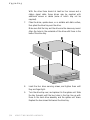
1
OWNER’S HANDBOOK
Apricot 340
apricot
MITSUBISHI ELECTRIC
APRICOT 340 & XEN PC
OWNER’S HANDBOOK
APRICOT
APRICOT
APRICOT
APRICOT
VS340
MS340
LS340
XEN PC
Intel and Pentium are registered trademarks of Intel Corporation.
Microsoft, MS-DOS, Windows, and Windows 95 are registered trademarks
of Microsoft Corporation.
SIMM is a registered trademark of Wang Laboratories.
LOC Technology and KeyLOC are trademarks of Apricot Computers
Limited.
Other trademarks are the properties of their respective owners.
Information contained in this document is subject to change without notice
and does not represent a commitment on the part of Apricot Computers
Limited. Any software described in this manual that has been supplied with
this computer is supplied subject to a license agreement. The software may
be used or copied only in accordance with the terms of this agreement. It
may be an offence punishable by law to copy any disk or part of a disk
supplied for any other purpose than the purchaser’s personal use unless
specifically authorized within the licence agreement.
All rights reserved. No use or disclosure or reproduction of this manual, in
any form, is permitted without prior written consent from the publishers.
Copyright © Apricot Computers Limited 1995
Published by:
Apricot Computers Limited
3500 Parkside
Birmingham Business Park
B37 7YS
MITSUBISHI ELECTRIC
Printed in the United Kingdom
Safety & Regulatory Notices
Safety and Regulatory Notices
Read the separate Power Connection Guide and Health and Comfort
Guide before using the computer for the first time.
Electrical
The computer uses a safety ground and must be earthed. The system
unit AC power cord is its “disconnect device”. Ensure that the system
unit is positioned close to the AC power outlet, and that the plug is
easily accessible.
The power cord packed with the computer complies with the safety
standards applicable in the country in which it is first sold. Use only
this power cord. Do not substitute a power cord from any other
equipment.
It is imperative that the system unit is set to the correct voltage range
before use. If not, the machine may be irreparably damaged.
To prevent fire and electric shock, do not expose any part of the
computer to rain or moisture.
Turn off the computer and unplug all power cords before moving
the system unit, cleaning the computer or removing the system unit
top cover.
Battery
This product contains a replaceable lithium battery.
Do not use a metal or other conductive implement to remove the
battery. If a short-circuit is made between its positive and negative
terminals, the battery may explode.
Replace a discharged battery with one of the same type; another
type may explode or ignite. Follow the instructions contained in the
Owner’s Handbook to replace the battery.
Dispose of a discharged battery promptly and in accordance with
the manufacturer’s recommended instructions.
APRICOT 340 OWNER’S HANDBOOK
i
Safety & Regulatory Notices
Do not recharge, disassemble or incinerate the discharged battery.
Keep away from children.
Laser products
Any CD-ROM drive fitted in this system is classified as a CLASS 1
LASER PRODUCT according to IEC825 Radiation Safety of Laser
Products (Equipment Classification: Requirements & User’s Guide). The
CLASS 1 LASER PRODUCT label is located on the underside of
the system unit or on the door to the removable-media drive bay.
The CD-ROM drive contains a laser system which is harmful to the
eyes if exposed. Do not attempt to disassemble the CD-ROM drive;
if a fault occurs, call an authorized maintainer.
Use the CD-ROM drive only as described in this manual; failure to
do so may result in exposure to hazardous radiation.
Ergonomic
When positioning the system unit, monitor and keyboard, take into
account any local or national regulations relating to ergonomic
requirements.
Acoustic noise
German Acoustic Noise Regulation
Sound power level is less than 70 dB(A) according to DIN 45635
Part 19 (ISO 7779).
Die Deutsche Akoustische Lärm-Regulierung
Der Grad der Klangstärke ist weniger als 70 dB (A) je nach DIN
45635 Teil 19 (ISO 7779).
ii
APRICOT 340 OWNER’S HANDBOOK
Safety & Regulatory Notices
Safety
This equipment complies with the following European safety
standards:
EN60950
Electromagnetic compatibility (EMC)
This product complies with the following European EMC standards:
Emissions
EN55022 Class B
Immunity
EN50082-2
Harmonics
EN60555 Parts 2 and 3
To ensure continued compliance:
♦
All ancillary equipment using an AC power cord must be
earthed.
♦
All interconnecting cables (e.g. cables for microphones,
headphones or external speakers), and communication cables,
must be less than 2 metres in length. If cable extensions are
used, ensure that adequate earth connections are provided and
that screened cables used.
♦
Use only Apricot tested and approved upgrades.
Failure to observe these requirements cancels Apricot’s responsibility
for this product’s European EMC compliance.
European Directives
This equipment complies with the relevant clauses of the following
European Directives:
Low Voltage Directive
73/23/EEC
EMC Directive
89/336/EEC
CE Marking Directive
93/668/EEC
APRICOT 340 OWNER’S HANDBOOK
iii
Safety & Regulatory Notices
Thermalcote bonding compound
The thermal bonding compound used between the system processor
and its heat sink can cause skin irritation and stain clothing. Avoid
prolonged or repeated contact with skin. Wash thoroughly with
soap and water after handling. Avoid contact with eyes and
inhalation of fumes. Do not ingest.
iv
APRICOT 340 OWNER’S HANDBOOK
Contents
CONTENTS
1
2
Introducing...
Unpacking
1/1
Pictorial guide to the system unit
1/2
Summary of features
1/6
Getting Started
General advice
2/2
Connecting the components
2/3
Turning on and booting the computer
2/5
Backing-up the pre-installed software
2/8
Using the 3.5-inch diskette drive
2/9
Using Help
3
2/11
Using the BIOS Setup Utility
Starting BIOS Setup
3/2
If BIOS Setup starts on its own
3/2
Control keys
3/3
Main menu screen
3/5
System Summary
3/6
Devices and I/O Ports
3/6
Date and Time
3/8
System Security
3/8
Start Options
3/11
Advanced Setup
3/12
APRICOT 340 OWNER’S HANDBOOK
1
Contents
4
5
6
7
2
ISA Legacy Resources
3/13
Power Management
3/14
Using Floppy Disk, CD-ROM and Tape Drives
Using a 5.25" floppy disk drive
4/1
Using a CD-ROM drive
4/3
Using an FTD Travan tape drive
4/5
Using a SCSI QIC tape drive
4/8
Using a SCSI DDS-2 tape drive
4/9
Maintaining and Transporting
Cleaning the computer
5/1
Transporting the computer
5/3
Using the computer in another country
5/3
Adding Expansion Cards
Configuring the card
6/3
Installing the card
6/8
Upgrading
Inside the system unit
7/2
Adding more system memory
7/4
Adding cache memory
7/8
Adding more video memory
7/10
Upgrading the processor
7/12
Adding a removable-media drive
7/16
Adding a hard disk drive
7/21
APRICOT 340 OWNER’S HANDBOOK
Contents
8
A
Troubleshooting
Problems when starting
8/1
Troubleshooting checklist
8/5
Inside the System Unit
Anti-static precautions
A/1
Opening the system unit
A/3
Motherboard layout
A/4
System connectors
A/6
Changing jumper settings
A/7
Replacing the configuration battery
B
A/10
Technical Information
Specifications
B/1
Physical characteristics
B/6
Electrical characteristics
B/6
Port characteristics
B/8
APRICOT 340 OWNER’S HANDBOOK
3
Introducing
1
INTRODUCING . . .
This chapter gives you a quick tour of your new Apricot computer.
As soon as you’ve unpacked the components and familiarised
yourself with them, you should progress to the next chapter,
“Getting Started”.
Warning
Read the separate Power Connection Guide before using the computer for the
first time.
Unpacking
On unpacking the computer, you should find:
♦
Apricot PC system unit.
♦
Apricot/Mitsubishi monitor and accompanying User’s Guide.
♦
Apricot extended keyboard and two-button mouse.
♦
System unit AC power cord, and monitor power cord,
appropriate for the country of sale.
♦
System documentation (this Owner’s Handbook, etc.)
♦
Microsoft Windows 95 or (if requested) Microsoft MS-DOS
and Windows for Workgroups documentation.
More elaborate systems may include software or hardware options
with accompanying installation diskettes and additional
documentation. Some of these options may have been factoryconfigured or installed by your supplier.
Keep the cartons, boxes and packaging materials; you will need
them again if you have to transport the computer elsewhere.
Make a note of the manufacturer’s data recorded on the various
components (product codes, serial numbers, etc.). A service engineer
may need this information if the computer develops a fault.
APRICOT 340 OWNER’S HANDBOOK
1/1
Introducing
3
4
2
1
5
4
6
7
Pictorial guide to the system unit
1/2
APRICOT 340 OWNER’S HANDBOOK
Introducing
1
POWER button: press to turn the system on or off. The green
indicator on the button lights when the system unit is
powered.
2
activity indicators, from left to right:
lights when a diskette, floppy disk or FTD Travan tape
drive is in use (depending on the operating system).
lights when a hard disk drive or SCSI tape drive is in use
(depending on the operating system).
3
infrared sensor: fitted only on Apricot LS340 models with a
built-in LOC Technology system.
4
speaker grille: Apricot MS340 and LS340 models have
internal stereo speakers. Apricot VS340 and XEN PC models
have a single internal speaker (right-hand side).
5
door (shown closed): hinges down to reveal the removablemedia drive bay.
6
3.5" diskette drive.
7
system lock: prevents unauthorized access to the inside of the
system unit.
APRICOT 340 OWNER’S HANDBOOK
1/3
1
2
10
3
4
5
6
7
11 12 13 14
15 16
8
17
9
10
18
Introducing
1/4
APRICOT 340 OWNER’S HANDBOOK
Introducing
1
AC power outlet: where the monitor power cord can plug in.
2
voltage selection switch: the system unit can be set to
operate with a 100-120 V or 220-240 V AC power supply.
3
AC power inlet: where the system unit power cord plugs in.
4
keyboard port: connect the keyboard to this port.
5
mouse port: connect the mouse to this port.
6
serial port 1: (110 baud to 9600 baud): typically used for
connecting an external modem or a serial printer signal cable.
7
serial port 2: identical to serial port 1.
8
parallel port (standard, bi-directional or ECP/EPP): typically
used for a printer signal cable.
9
monitor port: connect the monitor signal cable to this port (if
you are using the on-board graphics system).
10
casing screws: unfasten these to remove the top cover.
11
joystick/MIDI port: (MS/LS models) intended for either a
standard PC analog joystick, or a MIDI In/Out adapter.
12
audio input socket (MIC): (MS/LS models) mainly intended
for a microphone. Alternatively, you could attach a personal
stereo (tape or CD). The socket provides “phantom power” for
electret condenser type microphones.
13
line in socket (IN): (MS/LS models) intended for a line-in
signal from a high-fidelity tape deck or CD player.
14
line out socket (OUT): (MS/LS models) intended for a lineout signal to a high-fidelity amplifier or tape deck.
15
audio output socket (SPK): (MS/LS models) intended for
headphones or a pair of external self-powered loudspeakers.
16
security loop: you can feed a security chain through this loop
and secure it to prevent theft of the system unit.
17
blanking plates: for the expansion card slots.
18
air vents: do not block these vents or the system will overheat.
APRICOT 340 OWNER’S HANDBOOK
1/5
Introducing
Summary of features
This section is intended mostly for people who already know a bit
about computers and want to get an idea of what this one can do.
Don’t worry if you’re unfamiliar with some of the computer
terminology used here. It’s provided as a useful “shorthand” for more
experienced readers. Be assured, you don’t need to understand any
jargon to use the computer safely and efficiently. (On the other
hand, it can’t hurt to learn; introductory books about computers can
be found in your local bookshop or library.)
The Apricot 340 range is divided into three series. The economical
VS-series (Apricot VS340 and Apricot XEN PC), the multimedia
MS-series (Apricot MS340), and the business-minded LS-series
(Apricot LS340 and Apricot LS340E).
Standard features
The standard features of the range include:
1/6
♦
Intel Pentium processor with upgrade capability.
♦
8 Mbytes of system random-access memory (RAM),
upgradeable to 128 Mbytes by the use of standard 32-bit,
70 nanosecond SIMMs (single in-line memory modules).
Extended Data Output (EDO) SIMMs are supported.
♦
BIOS Setup configuration utility in read-only memory (ROM).
♦
Cirrus Logic CL-GD543x local bus Enhanced Video Graphics
Array (EVGA) controller with at least 1 Mbyte of video
memory, upgradeable to 2 Mbytes.
♦
Primary and secondary local bus Integrated Drive Electronics
AT-Attachment (IDE/ATA) interfaces for IDE hard disk drives
and ATA-PI (ATA Packet Interface) CD-ROM drives
respectively.
APRICOT 340 OWNER’S HANDBOOK
Introducing
♦
1.44 Mbyte 3.5" diskette drive; 3.5" hard disk drive bay with
room for two one-inch drives (various capacities); one 5.25"
removable-media drive bay.
♦
Peripheral Component Interconnect (PCI) and Industry
Standard Architecture (ISA) expansion card slots: one fulllength PCI/ISA slot, one full-length ISA slot, and (in cacheless
models) one half-length ISA slot.
♦
Parallel port with either standard, EPP (Enhanced Parallel
Port) or ECP (Extended Capabilities Port) functionality; two
serial ports; extended keyboard; two-button mouse.
Energy-efficient features
All models in the range comply with the requirements of the US
Environmental Protection Agency’s “Energy Star” programme for
energy-efficient computers. These models support:
♦
System Management Mode (SMM) of Intel SL Enhanced
processors.
♦
Operating systems and applications that use the
Intel/Microsoft Advanced Power Management (APM) interface
standard.
♦
VESA BIOS Extensions for Power Management (VBE/PM), for
use with energy-efficient monitors that support Display Power
Management Signalling (DPMS).
Caution
Do not attempt to use the computer’s energy-saving features with a
monitor that does not support DPMS; the monitor may be permanently
damaged.
APRICOT 340 OWNER’S HANDBOOK
1/7
Getting Started
2
GETTING STARTED
You should read this chapter even if you do not read any other. It
provides important information to help you site, connect, power and
configure the computer.
This chapter will tell you all you need to know in order to start
work. The chapters after this one deal with the BIOS Setup utility
and various removable-media drives.
Warning
Read the separate Power Connection Guide before using the computer for the
first time.
APRICOT 340 OWNER’S HANDBOOK
2/1
Getting Started
General advice
This computer is designed to be used in a normal home or office
environment. Here are a few hints for choosing a suitable site:
♦
Place the system unit flat on a sturdy, level surface. Unlike
some other computers, the system unit is not designed to be
stood on its side.
♦
Site the computer away from moisture, direct sunlight, and
extremes of heat and cold. Avoid situations in which the
surrounding temperature or humidity may change rapidly. (See
Appendix B, “Technical Information”, for recommended
temperature and humidity ranges.)
♦
When positioning the system unit, monitor and keyboard, take
into account any local or national regulations relating to
ergonomic requirements. For example, you should ensure that
little or no ambient light is reflected off the monitor screen as
glare, and that the keyboard is placed in a comfortable position
for typing.
♦
Give the computer plenty of room so that air can circulate on
all sides. Air is drawn into the system unit through vents on the
bottom and on the left-hand side, and expelled through the
vent on the back. Ensure that these vents are never obstructed.
Do not allow any cables, particularly power cords, to trail across the
floor where they can be snagged by people walking past.
Warning
The computer uses the system unit AC power cord as its “disconnect device”.
Ensure that the system unit is positioned close to the AC power outlet, and that
the plug is easily accessible.
To prevent fire and electric shock, do not expose any part of the system unit to
rain or moisture.
2/2
APRICOT 340 OWNER’S HANDBOOK
Getting Started
Connecting the components
See Chapter 1, “Introducing...”, if you need help identifying the
various ports on the system unit.
Checking the AC power supply
When the computer is delivered, it is ready for the commercial AC
power supply generally available in the country in which it is first
sold. It has been set for the correct voltage range, and is supplied
with an AC power cord and plug which comply with the relevant
safety standards.
Before using the computer in a country other than that in which it
was originally sold, you must check the voltage and frequency of
that country’s AC power supply, and the type of power cord
required there. Check the power rating labels on the rear of the
computer’s system unit and its monitor to ensure that they are
compatible with the AC power supply.
If necessary, the AC voltage setting of the system unit can be
adjusted by the voltage selection switch on the rear of the system
unit. Refer to the chapter on “Maintaining and Transporting”, for
instructions on how to do this. It is likely that the monitor’s voltage
setting will also need adjusting; consult the User’s Guide that
accompanies the monitor, or ask your supplier for help.
Installing add-on options
If the computer arrived with uninstalled add-on options, (such as
expansion cards or memory modules) consult the relevant chapters in
this Owner’s Handbook for step-by-step installation instructions.
Expansion cards may also have their own documentation that
supplements or overrides the instructions in this manual.
Note that some options for which you have installation guides may
have already been installed for you at the factory or by your
supplier.
APRICOT 340 OWNER’S HANDBOOK
2/3
Getting Started
Connecting the components
Having assured yourself that the voltage settings, and the AC power
cords of the computer, the monitor and any other peripherals, are
correct, use the procedure below to connect these components
together. It is important that you take each step in the order
indicated.
1.
If your AC power outlets have switches, set them to their Off
positions.
2.
Ensure that the system unit, the monitor, and any peripherals
are turned off.
3.
Connect the monitor signal cable between the monitor and the
monitor port on the rear of the system unit. (If the monitor
signal cable is connected after the computer is turned on, the
display may appear in monochrome or not at all.)
4.
Where appropriate, connect other signal cables between your
peripherals and their respective ports on the system unit. Make
sure the signal cables are connected securely.
5.
Plug the keyboard cable into the keyboard port on the system
unit. Be careful not to plug it into the mouse port by mistake.
6.
Plug the mouse into the mouse port on the system unit. Never
connect either the keyboard or the mouse while the system
unit is turned on.
7.
Where appropriate, connect the computer to the network.
8.
Connect the monitor power cord between the monitor and the
AC power outlet on the rear of the system unit.
9.
Connect the system unit power cord between the AC power
inlet on the rear of the system unit and a nearby, grounded AC
power outlet.
10. Where appropriate, connect power cords between your
peripherals and nearby, grounded AC power outlets.
11. If your AC power outlets have switches, set them to their On
positions.
2/4
APRICOT 340 OWNER’S HANDBOOK
Getting Started
Turning on and booting the computer
Turning the power on
To turn on the computer, simply press the POWER button. The green
indicator on the POWER button lights to show that the system unit is
powered. Remember that the monitor has its own power button or
switch; see the monitor’s User’s Guide for details.
Always make sure that the system unit is turned on before turning
on any attached peripherals.
If the computer does not start when the P OWER button is pressed,
check that the system unit and monitor power cords are securely
connected and that the AC power supply is switched on.
Power-on self-test
Whenever the computer is turned on, a power-on self-test (POST)
routine test various hardware components and compares the actual
configuration of the computer with that recorded in configuration
(CMOS) memory. During this time, BIOS sign-on and POST
messages are displayed.
The boot sequence
Provided that POST succeeds without discovering any serious errors
or configuration discrepancies, the computer attempts to find an
operating system; that is, it attempts to boot.
By default, the computer will look first for a system diskette, then
for a bootable hard disk, but this sequence can be changed with the
BIOS Setup utility.
System diskette
A system diskette is a diskette bearing at least the rudiments of an
operating system. If the computer finds such a diskette in the
diskette drive, it boots from it. If it finds a non-system diskette, the
computer invites you to replace it. If necessary, your operating
system manuals should tell you how to create a system diskette.
APRICOT 340 OWNER’S HANDBOOK
2/5
Getting Started
Hard disk
Apricot computers fitted with a hard disk normally arrive with either
Microsoft Windows 95 or the MS-DOS/Windows operating system
already in place or pre-installed, so that it’s there ready for you
when you turn on the computer for the first time.
Note
A hard disk may contain more than one operating system, in different
partitions, but only one partition can be active at any one time. The computer
loads its operating system from the currently active partition.
Starting the computer for the first time
The first time you turn on your computer a message appears
explaining the legal terms and conditions that govern the use of the
software pre-installed on the computer’s hard disk. Once you have
read this message, you can press F3 to continue. By doing so you are
acknowledging that you have read, understood and accepted the
terms and conditions.
Why your computer may seem to stop working
Your computer has a built-in energy-saving feature. If you leave it
for a while without doing anything, it goes into a special low-power
standby mode. The monitor display goes blank and the processor
slows down. The operating system and your programs continue to
run, although slowly (and of course you can’t see them because the
monitor is blank). The computer is still working, and you haven’t
lost any of your files.
You can wake the computer again by pressing any keyboard key.
See the chapter on “Using the BIOS Setup Utility” for more
information.
Caution
The monitor supplied with your computer is designed to work with these
energy-saving features. If you want to use another monitor, make sure that it
supports the VESA standard for Display Power Management Signalling; if it
doesn’t, it may be permanently damaged.
2/6
APRICOT 340 OWNER’S HANDBOOK
Getting Started
Turning the power off
Before turning off the computer, run through the following
checklist:
♦
Quit or exit from the applications you are running; be sure to
save any files you have altered. Any unsaved information still
held in the computer’s memory will be lost when you turn off
the computer.
♦
If you are logged-in to a network, logout before turning off
the computer. This gives the network operating system a
chance to free up the network resources you’ve been using.
♦
Close down or quit any software that employs virtual memory
or disk-caching (Windows 95 and Windows for Workgroups
do this automatically).
♦
Always turn off any attached peripherals first. However, there’s
no need to turn off the monitor if it’s being powered from the
system unit.
♦
Wait until all the activity indicators on the front bezel are unlit.
To turn off the computer, simply press the P OWER button again. The
power indicator on the button goes out. If the monitor is powered
from the system unit, it will be turned off at the same time.
After you turn the computer off, wait at least 5 seconds before
turning it on again. The computer may not initialize itself properly if
you turn it off then on again in quick succession.
APRICOT 340 OWNER’S HANDBOOK
2/7
Getting Started
Backing-up the pre-installed software
Apricot computers with a hard disk normally arrive with an
operating system pre-installed. The hard disk also contains a
complete set of Cirrus Logic video display drivers, although initially
the computer is configured to use the standard VGA Windows
driver. Additional software may be pre-installed by your supplier.
We recommend that you copy or back up any pre-installed software
soon after setting up the system. This is particularly important for
systems which are supplied without installation diskettes for the
software on the hard disk. A back up copy will safeguard the preinstalled software against loss if the hard disk fails or if you
accidentally overwrite or delete files.
♦
A disk imaging utility is provided with Windows 95 and
Windows for Workgroups. This allows you to create
installation diskettes for the operating system, and some other
software, from disk images pre-installed on the hard disk. See
the utility’s on-line help for more information.
♦
To back up other pre-installed software (and your own files)
use the Backup tool in the System Tools folder (if you have
Windows 95) or Backup for Windows (if you have Windows
for Workgroups).
Any copy you make of pre-installed software must be used only as a
back-up copy, in case the pre-installed version is lost. You are not
allowed to use installation diskettes created from disk images to
install the software onto another computer.
2/8
APRICOT 340 OWNER’S HANDBOOK
Getting Started
Using the 3.5-inch diskette drive
The 3.5-inch diskette drive can read and write double-sided
diskettes with a formatted capacity of either 1.44 Mbytes (if marked
“HD” or “high density”) or 720 Kbytes (if unmarked, or marked
“DD” or “double density”).
Each diskette has a rigid plastic cover with a metal shutter that
guards the disk surface. The drive automatically moves the shutter
aside to read the diskette. Never touch the exposed surface under the
shutter; you could deform the disk or leave a fingerprint that might
make the diskette difficult to read.
Keep diskettes well away from dust, moisture, magnetic objects, and
equipment that generates magnetic fields. Also, avoid extremes of
temperature and exposure to direct sunlight. Otherwise, data
recorded on the diskette may become corrupted.
Inserting a diskette
A diskette is inserted into the diskette drive slot shutter-foremost,
and with its label side facing up (see diagram). Some diskettes have a
small arrow on the face of the diskette; this must point towards the
drive when you insert the diskette.
Push the diskette all the way in until it engages with the drive
mechanism. When the drive’s EJECT button pops out, the diskette is
fully engaged.
APRICOT 340 OWNER’S HANDBOOK
2/9
Getting Started
Removing a diskette
Before attempting to remove a diskette, make sure that the drive is
not currently in use (the diskette activity indicator on the computer’s
front bezel must be unlit).
Press the EJECT button on the drive. The drive mechanism
disengages and the diskette is ejected half-way out of the drive.
If a diskette becomes stuck in the drive, perhaps because its label has
peeled back, do not attempt to remove it with tweezers or any
similar implement; you risk damaging the drive. Call an authorized
maintainer.
Write-protecting a diskette
A diskette can be write-protected by sliding a small tab towards the
edge of the diskette to expose the little hole beneath it (see
diagram). With the tab in this position, you can read, copy or print
files from the diskette, but you cannot create, rename or delete any
files.
The BIOS Setup utility can completely disable the diskette drive.
2/10
APRICOT 340 OWNER’S HANDBOOK
Getting Started
Using Help
Along with the software pre-installed on your computer’s hard disk,
you will often find one or more Apricot Help files. These will
explain any special features of the system, and tell you how to install
the software needed to exploit those features.
Apricot Help may be supplied in various forms, depending on the
intended operating system; for the Microsoft Windows 95 and MSDOS/Windows operating systems, they are usually Windows Help
files or README text files.
Apricot’s Windows Help files are usually pre-installed in the Apricot
folder (Windows 95) or program group (Windows for Workgroups).
Apricot’s README.1ST files, or other ASCII text files identified by
their .TXT file extensions, can be read by most text editors and
wordprocessing programs. Alternatively they can be displayed, one
screenful at a time, using the MS-DOS commands Type and More;
for example:
TYPE README.1ST | MORE
APRICOT 340 OWNER’S HANDBOOK
2/11
Using the BIOS Setup Utility
3
USING THE BIOS SETUP UTILITY
BIOS (pronounced “bye-oss”) stands for basic input/output
system. The BIOS operates at the boundary between the computer’s
hardware (the processor, memory, and so on) and its software (the
operating system and your programs), and effectively mediates
between the two.
The BIOS is permanently encoded in an area of read-only memory
(ROM), although it can be modified if necessary by an authorized
maintainer.
BIOS Setup is a utility programmed into the computer’s BIOS
ROM. Its main purpose is to allow you to view and alter the
computer’s hardware configuration. It is also used to configure
various security and power-saving options. Configuring the
computer is necessary to ensure that the software you use can
recognise and exploit the hardware’s capabilities.
The current configuration is kept in a special area of memory, called
CMOS memory, and maintained by a small battery so that the
configuration is preserved even while the computer is switched off.
Your computer arrives already configured, but may need to be
configured again after you add or remove add-on options such as
memory modules or expansion cards.
APRICOT 340 OWNER’S HANDBOOK
3/1
Using the BIOS Setup Utility
Starting BIOS Setup
Not long after turning on your computer, this symbol appears in the
top right corner of the screen:
~~~~
~~
~~~~
~~
~~~~
~~
While this symbol is displayed, you can press the F1 key to start the
BIOS Setup utility.
If BIOS Setup starts on its own
This can happen for three reasons:
3/2
♦
POST detects a configuration error or fault. This may be
signalled by one or more of the POST error messages listed in
the “Troubleshooting” chapter. If a persistent fault is indicated,
make a note of any error messages and the current
configuration settings before calling an authorized maintainer.
♦
The CMOS battery may be running down. This may be
signalled by spurious POST error messages. If this happens
every time you turn on the computer, you may have to change
the battery as described in Appendix A.
♦
The computer’s configuration may have changed, for example
by the addition of more system memory, more cache memory,
or an expansion card. In this case you may have to define the
new configuration.
APRICOT 340 OWNER’S HANDBOOK
Using the BIOS Setup Utility
Control keys
A number of keys are used to move around the BIOS Setup utility,
select items on the screen and change the current configuration. The
two lines at the bottom of the screen indicate what you can do at
any given time.
To select a line, press the UP ARROW and DOWN ARROW keys until
the line you want is highlighted. If there are more lines than fit on
one screen, the screen will scroll. The PAGE UP and PAGE DOWN keys
also work. To choose a selected action, press ENTER.
To exit from a screen, press the ESC key. To get help, select a line
and press F1.
Some lines are for information only. Others have fields you may
change. Changeable fields are enclosed in square brackets. Most
changeable fields allow you to select one of a few possible values.
To select a different value, use the LEFT ARROW and RIGHT ARROW
keys. Some changeable fields require you to enter a number. You
may type numbers, press the PLUS (+) key to increment the current
value or MINUS (–) to decrement it.
To restore the previous setting for a line, press F9. To restore the
default setting, press F10.
Press ESC at the main menu to exit from the utility. You are asked
whether or not you want to save any changes you have made to the
configuration in the computer’s CMOS memory. If you save the
changes, the computer will reboot on exiting the utility.
The table on the next page summarizes these controls.
APRICOT 340 OWNER’S HANDBOOK
3/3
Using the BIOS Setup Utility
3/4
Press
To
UP ARROW
DOWN ARROW
Move the highlight bar around the screen from one
line or one field to another.
LEFT ARROW
RIGHT ARROW
Scroll through the possible selections for the
currently-highlighted item.
ENTER
Choose the currently-highlighted item.
PAGE UP
PAGE DOWN
Move between the pages of the current screen.
F1
View a pop-up help dialog on the currentlyhighlighted item. Press F1 again to get general
help on Setup. Press ESC to close the help dialog.
F9
Restores the previous setting for the currently
selected item.
F10
Restores the BIOS default setting for the currently
selected item. This setting may not be appropriate
for your particular system.
ESC
Exit the current screen. To exit BIOS Setup, press
ESC in the main menu screen. When you exit BIOS
Setup after saving changes, the computer reboots.
APRICOT 340 OWNER’S HANDBOOK
Using the BIOS Setup Utility
Main menu screen
When you start BIOS Setup a main menu screen appears with the
following options:
•
•
•
•
•
•
•
•
System Summary
Devices and I/O Ports
Date and Time
Security
Start Options
Advanced Setup
ISA Legacy Resources
Power Management
Save Settings
Restore Settings
Load Default Settings
Exit Setup
Lines with a bullet in front of them have further menus or dialog
boxes associated with them, and are described later in this chapter.
A
bullet next to a line indicates that BIOS Setup detected a
configuration error and attempted to correct it.
The Save Settings option saves any changes that you have made so
far.
The Restore Settings option restores the settings that were in effect
when you started the BIOS Setup utility (with the exception of the
Date and Time settings).
The Load Default Settings option restores the BIOS default settings.
Caution
The BIOS defaults may not be appropriate for your particular system. Make a
note of the current settings before using the Load Default Settings option or
pressing F10.
APRICOT 340 OWNER’S HANDBOOK
3/5
Using the BIOS Setup Utility
System Summary
This page cannot be edited, but gives a summary of the main system
settings. Changes made in other pages will be reflected here. Make a
note of the information on this page before you make any changes.
Devices and I/O Ports
Serial Ports A & B (COM1 & COM2)
This allows you to select the I/O ports and interrupts used by the
two serial ports. It is best to leave these at the default settings. Do
not disable the serial ports unless you are absolutely sure you are not
going to need them.
Parallel Port
This allows you to set the I/O port and interrupt used by the
parallel port. You can select Standard or Extended port modes. To
get EPP mode you may have to change the I/O port setting.
Parallel port mode
Description
Standard
Used for output only.
Extended
Bi-directional
Simple two-way data.
EPP
Enhanced Parallel Port mode.
ECP
Extended Capabilities Port mode.
Any parallel port devices that you may wish to attach, such as a tape
streamer or external hard drive, should have full instructions
supplied with them that will tell you if the port capabilities need to
be altered to one of the extended options above.
Diskette Drives A & B
This lets you specify what diskette and floppy disk drives are fitted.
Diskette drive A, which is fitted by default, is invariably a 1.44
Mbyte 3.5" drive. If a second floppy disk is fitted, it is usually a 1.2
Mbyte 5.25" drive.
3/6
APRICOT 340 OWNER’S HANDBOOK
Using the BIOS Setup Utility
Mouse
This option enables the use of a mouse. The actual presence of a
mouse can then be detected by POST. You should not normally
disable this option.
IDE Drives Setup
The motherboard’s two IDE/ATA (Integrated Drive Electronics ATAttachment) interfaces support a total of four drives (that is, two
drives per interface).
However, the computer itself can accommodate at most two hard
disk drives plus one removable-media drive, typically a CD-ROM
drive. The hard disk drives should be connected to the primary IDE
interface, and the CD-ROM drive connected to the secondary
interface.
Hard disk drives
Hard disk size and type is auto-detected when the computer is
turned on, but two other parameters can be manually set for each
drive.
Parameter
Settings
IDE Performance
High Performance mode allows the
system to make use of any performance
enhancement features the drive may have.
You should select Compatible mode for
older hard disk drives or drives that do
not follow the IDE/ATA specification.
IDE Translation Mode
Select Extended CHS (cylinder, head,
sector) to enable the scheme that allows
the BIOS to access hard disk drives of
greater than 504 Mbytes capacity. You
might need to select Standard CHS if your
operating system does not support
Extended CHS for large drives.
APRICOT 340 OWNER’S HANDBOOK
3/7
Using the BIOS Setup Utility
CD-ROM drives
The BIOS will detect the presence of a CD-ROM drive when the
computer is turned on. It will be shown as CD-ROM Drive 2
(allowing for Hard Disk Drives 0 and 1). You can manually
configure the IDE Performance parameter of the CD-ROM drive in
the same way as a hard disk drive.
Date and Time
Use this to adjust the motherboard’s Real Time Clock (RTC). This
clock is maintained by a battery while the computer is turned off.
Time
The time is in 24-hour format. Use the LEFT ARROW and RIGHT
keys to move from hours to minutes to seconds. To enter
new values use the number keys, or the PLUS (+) and MINUS (–) keys
to increase or decrease the number.
ARROW
Date
The date is in the usual Day/Month/Year format. The procedure for
altering the date is the same as for altering the time.
Once the correct date is set you should not need to set it again. The
computer accounts for leap years automatically.
System Security
This is to allow you to set, change or delete passwords for either
general or administrator use. You can also control access to the
computer’s hard disk and diskette drives.
The password options are intended for computers that lack more
sophisticated security systems. You should not use these options on
an Apricot LS340 computer with a built-in LOC Technology
security system.
3/8
APRICOT 340 OWNER’S HANDBOOK
Using the BIOS Setup Utility
Secure Hard Disk Drives and Diskette Drives
Use these options to disable or enable access to the hard disk drives
(including CD-ROMs) and diskette drives (including FTD tape
drives).
Caution
Do not disable both hard disk drives and diskette drives, or the computer will
be unable to find and load an operating system. Be careful not to disable the
startup device(s) specified under the Start Options menu (see below).
Power-on Password
This option allows you to set a password that is required every time
the computer is turned on or rebooted. Only people who know the
password will be able to use the computer. The password can be up
to seven characters long.
To define a power-on password:
1.
In the Power-on Password dialog, type the password in the
Enter Power-on Password box, then press the DOWN ARROW
key.
2.
Type the password once more in the Enter Power-on Password
Again box.
To preserve confidentiality, the password is not displayed as
you type it.
3.
If you want the computer to ask for the power-on password,
ensure that Password Prompt is set to “On”. If this option is set
to “Off”, the computer will still require the password but will
not ask for it.
4.
Choose the Set Or Change Power-on Password option.
A dialog asks you to confirm that you want to replace any
existing power-on password.
5.
Press ENTER to confirm (or ESC otherwise).
APRICOT 340 OWNER’S HANDBOOK
3/9
Using the BIOS Setup Utility
Now, when the computer is next turned on or rebooted, the user is
required to enter the password. If the Password Prompt option is set
“On”, the following prompt is displayed:
Type your password, then press Enter.
If the Password Prompt option is set “Off”, the user is not prompted
at all. The computer will boot (or if F1 is pressed during start-up the
BIOS Setup utility will start) and then wait for the user to type the
password and press ENTER. It is important that authorized users of
the computer are told to expect this, or they may think that the
computer has stopped working.
The user is allowed three attempts to enter the correct password. If
she fails, the system is “locked” and must be turned off. Turning the
computer on again restarts the sequence.
To delete a power-on password:
1.
In the Power-on Password dialog, choose the Delete Power-on
Password option.
A dialog asks you to confirm that you want to delete the
existing power-on password.
2.
Press ENTER to confirm.
Administrator Password
An administrator password works in exactly the same way as a
power-on password. If you define both an administrator and a
power-on password, the computer accepts only the administrator
password.
3/10
APRICOT 340 OWNER’S HANDBOOK
Using the BIOS Setup Utility
Start Options
Certain features can be set or enabled automatically when the
computer boots.
Keyboard Numlock State
If set to “On”, the keys on the numeric keypad (on the right-hand
side of the keyboard) will produce numbers when pressed. If “Off”,
these keys provide cursor control functions instead.
Keyboard Speed
This sets the speed (frequency) at which a pressed key will repeat;
either “Fast” (the default) or “Normal”.
Disketteless Operation
If this option is “Disabled”, POST will look for and test the diskette
drive, and report an error if the drive is faulty or missing. If
“Enabled”, POST will omit the test and continue, provided that
another boot device is available (i.e. the hard disk drive).
Displayless Operation
If this option is “Disabled”, POST will look for an attached monitor
and report an error if it is missing; if “Enabled”, POST will allow the
computer to start without a monitor.
Keyboardless Operation
If this option is “Disabled”, POST will look for an attached
keyboard and report an error if it is faulty or missing; if “Enabled”,
POST will allow the computer to start without a keyboard.
Startup Devices
These options allow you to specify where the BIOS looks for an
operating system when it boots. If the computer cannot locate an
operating system on the First Startup Device, it tries the Second
Startup Device, and so on.
APRICOT 340 OWNER’S HANDBOOK
3/11
Using the BIOS Setup Utility
Note that if the First Startup Device is set to “Disabled”, the
computer will be unable to boot.
The possible settings depend on the number and type of devices that
are installed in your computer. For example, “Diskette Drive 1” is
not a possible setting if your computer does not include a second
floppy disk drive.
By default, the First Startup Device is “Diskette Drive 0” and the
Second Startup Device is “Hard Disk 0”. This should not normally
need to be changed.
Power On Self Test
The POST can be selected to either run only a “Quick” set of tests or
a more thorough (but longer) “Enhanced” set.
Virus Detection
If this option is “Enabled”, each time the computer boots the BIOS
will check the startup device to find out if a boot sector virus has
crept in. This is not an infallible check against the newer types of
virus, but it can help.
Advanced Setup
Any settings changed here, if incorrect, may cause the system to halt
or may cause your software to malfunction. A warning about this
appears on the screen when you choose Advanced Setup from the
menu.
Cache Control
A simple dialog allows you to enable or disable the computer’s
external memory cache (if fitted). Some older software is speed
sensitive and on rare occasions you may need to disable the cache.
See the chapter on “Upgrading” for more information about adding
cache memory.
3/12
APRICOT 340 OWNER’S HANDBOOK
Using the BIOS Setup Utility
ROM Shadowing
To shadow ROM means to copy its contents into the computer’s
system or random-access memory (RAM). This is beneficial for two
reasons: ROM has (relatively) long access times and the processor
can access RAM faster than ROM; second, the contents of RAM can
be cached for even greater performance. All of the computer’s system
BIOS ROM is shadowed.
The ROM Shadowing option allows you to shadow video BIOS and
up to three 32 Kbyte areas of expansion card ROM (that is, ROM
fitted on ISA or PCI expansion cards) addressed between C8000h
and EFFFFh.
See the chapter entitled “Adding Expansion Cards” for more
information about addressing expansion card ROM.
Note that the two 32 Kbyte areas from E0000h to E7FFFh and
E8000h to EFFFFh cannot be shadowed independently of the
system BIOS ROM.
Caution
Shadowing is only appropriate for expansion card ROM. It must not be
enabled for expansion card RAM.
PCI Settings
The only configurable PCI setting is Palette Snooping, which can be
“Enabled” or “Disabled”. It should be enabled only for PCI video
expansion cards that require it.
ISA Legacy Resources
After fitting an ISA expansion card in your computer, you should use
this option to mark as “Not Available” those system resources that
the card uses. This needs to be done because the BIOS cannot detect
their being in use, but must know about them so as to automatically
configure any “Plug and Play” devices and PCI cards to avoid
resource conflicts.
There is a separate option for each resource: memory, I/O ports,
DMA channels and interrupts. See the chapter entitled “Adding
APRICOT 340 OWNER’S HANDBOOK
3/13
Using the BIOS Setup Utility
Expansion Cards” for more information about the resources used by
expansion cards.
Each item shown as “Available” is assumed not to be in use by any
ISA card or device and will therefore be made available for the PCI
auto-configuring process. Some items are shown as “Allocated by the
system”, meaning that they are reserved for use by motherboard
devices.
Power Management
These power management features are provided to reduce the
average amount of electricity consumed by your computer. Some
features will have been enabled in our factory to ensure compliance
with the Energy Star programme. For more information about
Energy Star, see the Windows Help file pre-installed on your hard
disk.
Hard Disk Standby
If this option is “Enabled”, the hard disk drive will stop spinning or
spin down after about 20 minutes of inactivity.
Standby Time-out
If this option is not “Disabled”, the computer will go into a lowpower standby mode after the specified period of inactivity. The
processor slows down and, provided that the Monitor Power
Management option is also “Enabled”, the monitor display goes
blank. The operating system and your programs continue to run,
although slowly. You can wake the computer again by pressing any
keyboard key.
Monitor Power Management
This option is intended to be used only with monitors that support
Display Power Management Signalling (DPMS). If “Enabled”, the
monitor will go blank when the computer enters standby mode (see
above).
Another way of saving monitor power is by using the built-in
power-saving features of Windows 95, or the Cirrus Logic Display
3/14
APRICOT 340 OWNER’S HANDBOOK
Using the BIOS Setup Utility
Power Manager screen saver supplied with Windows for
Workgroups. See your Windows Help files for more information.
Caution
The monitor supplied with your computer is designed to work with these
energy-saving features. If you want to use another monitor, make sure that it
supports DPMS; if it doesn’t, it may be permanently damaged.
APRICOT 340 OWNER’S HANDBOOK
3/15
Using Floppy Disk, CD-ROM & Tape Drives
4
USING FLOPPY DISK, CD-ROM
AND TAPE DRIVES
This chapter contains information about the various optional
removable-media drives that are available. These include:
♦
5.25-inch floppy disk drive
♦
CD-ROM drive
♦
FTD Travan tape drive
♦
SCSI QIC quarter-inch cartridge tape drive
♦
SCSI DDS-2 (Digital Data Storage) tape drive
Using a 5.25" floppy disk drive
This drive can read and write double-sided disks with a formatted
capacity of either 1.2 Mbytes (if marked “HD” or “high density”) or
360 Kbytes (if marked “DD” or “double density”).
Each floppy disk is sealed into a flexible plastic envelope with a
long, rounded aperture through which the read/write heads of the
disk drive can meet the disk surface. You must never touch the
exposed surface of the disk yourself.
Keep floppy disks well away from dust, moisture, magnetic objects,
and equipment that generates magnetic fields. Also, avoid extremes
of temperature and exposure to direct sunlight. Otherwise, data
recorded on the disk may become corrupted.
Inserting a floppy disk
1.
Insert the disk into the drive slot with the read/write aperture
foremost.
2.
When the disk is fully inserted, turn the locking lever onequarter turn clockwise to engage the drive mechanism.
APRICOT 340 OWNER’S HANDBOOK
4/1
Using Floppy Disk, CD-ROM & Tape Drives
Removing a floppy disk
1.
Before attempting to remove a disk, ensure that the drive is not
currently in use (the drive’s LED must be unlit).
2.
Turn the locking lever one-quarter turn counter-clockwise to
disengage the drive mechanism. The diskette is ejected halfway
out of the drive.
3.
Pull the disk completely out of the drive.
Write-protecting a floppy disk
A floppy disk can be write-protected by covering the small notch in
the edge of the disk envelope (A) with a self-adhesive tab (B); such
tabs are typically supplied with new floppy disks. With the tab in
this position, you can read or print files from the disk, but you
cannot create, rename or delete any files.
A
4/2
APRICOT 340 OWNER’S HANDBOOK
B
Using Floppy Disk, CD-ROM & Tape Drives
Using a CD-ROM drive
With the appropriate software support, a CD-ROM drive can
retrieve multimedia data from CD-ROM discs and multisession
Photo-CD discs. It can also play commercial audio CDs.
1
COMPACT
2
1
2
3
4
5
3
4
5
disc drawer or platter
headphone jack and headphone volume control
activity indicator (green = powered, amber = busy)
emergency eject hole
EJECT button (works only when drive is powered)
The software required to control the drive depends on the type of
drive and the operating environment; see the Help provided with the
computer or ask your supplier for details.
The drive has its own headphone jack with associated volume level
control. These can be used to listen to music CDs, but not, usually,
to the audio on multimedia CDs such as games.
Do not attempt to move the computer while a CD is in the drive,
especially if the CD is being played at the time.
Warning
The laser beam inside the CD-ROM drive is harmful to the eyes if exposed.
Do not attempt to disassemble the CD-ROM drive. If a fault occurs, call an
authorized maintainer.
APRICOT 340 OWNER’S HANDBOOK
4/3
Using Floppy Disk, CD-ROM & Tape Drives
Inserting a compact disc
1.
Press the EJECT button on the front of the drive.
2.
If the platter only ejects halfway out of the drive, pull it out to
its fullest extent.
3.
Place the CD face up on the platter.
4.
If the platter ejected fully, push the EJECT button again, or
gently push the front of the platter, and it will be drawn back
into the drive. If the platter only ejected halfway, push the
platter in until it engages with the drive mechanism.
5.
Wait for the CD to spin up to speed before attempting to read
from it.
Removing a compact disc
1.
Before attempting to remove a CD, ensure that the computer is
turned on (otherwise the EJECT button will not work) and that
drive is not currently in use (the drive’s activity indicator must
be unlit).
2.
Press the EJECT button. The drive mechanism disengages and
the platter is ejected. (The EJECT button can be disabled by the
software controlling the CD-ROM drive. In this case pressing
the EJECT button will have no effect.)
3.
If the platter only ejects halfway out of the drive, pull it out to
its fullest extent.
4.
Remove the CD from the platter.
To eject the platter manually (for example, during a power failure)
you must first ensure that the computer is turned off. Then insert a
thin metal rod (such as an unwound paper clip) into the emergency
eject hole and push hard.
Keep CDs well away from dust and moisture, and avoid touching
the surface of the CD. Also, avoid extremes of temperature and
exposure to direct sunlight.
4/4
APRICOT 340 OWNER’S HANDBOOK
Using Floppy Disk, CD-ROM & Tape Drives
Using an FTD Travan tape drive
The FTD Travan tape drive uses the on-board diskette/floppy disk
interface and so does not require an additional drive controller card
like most other tape drives.
1
2
1 drive activity indicator (green)
2 flip-up door
The drive is designed for TR-1 or equivalent minicartridges (750 ft,
400 Mbytes). This nominal capacity can typically be doubled to 800
Mbytes by software data compression. The software required to
control the tape drive depends on your operating environment; ask
your supplier for details.
Note
The drive can also accept QIC-80 Wide cartridges (400 ft, 208 Mbytes) and
long-length QIC-80 cartridges (307.5 ft, 124 Mbytes).
Inserting a cartridge
1.
Remove the cartridge from its plastic holder.
2.
Hold the cartridge so that the metal plate faces downwards, as
shown below. Slide the cartridge into the drive slot until you
feel a slight resistance.
APRICOT 340 OWNER’S HANDBOOK
4/5
Using Floppy Disk, CD-ROM & Tape Drives
3.
Carefully push the cartridge in a bit further until it engages
with the drive mechanism. Once the cartridge is correctly
loaded, it protrudes about 12 mm from the drive.
Removing a cartridge
1.
Check that the cartridge is not being accessed by the computer
(the drive’s activity indicator must be unlit).
2.
Pull the cartridge carefully out of the drive slot, holding it
between thumb and forefinger.
3.
Return the cartridge to its plastic holder. This protects the
cartridge and prevents dust from collecting on the surface of
the tape.
Write-protecting a cartridge
A cartridge can be write-protected by sliding the red switch on the
cartridge to the locked position (marked with a closed padlock
symbol) as shown below.
4/6
APRICOT 340 OWNER’S HANDBOOK
Using Floppy Disk, CD-ROM & Tape Drives
Keep tape cartridges well away from magnetic objects, and
equipment that generates magnetic fields (for example, your
computer’s monitor). Avoid extremes of temperature and exposure to
direct sunlight; otherwise, the data recorded on the tape may
become corrupted.
Cleaning the drive
You should clean the read/write head and the capstan of the drive
frequently to prevent the accumulation of dust and metallic particles.
If you notice read or write errors, or many bad blocks when using
the drive, be sure to clean the head and capstan thoroughly before
concluding that the drive or your tapes are defective.
Although it is possible to use special kits to clean the drive, we
recommend the use of 90% isopropyl alcohol and several nonabrasive, lint free swabs, as follows:
1.
Turn off the system unit and unplug all power cords.
2.
The read/write head and the capstan are accessible through
the flip-up drive door.
3.
Gently rub an alcohol-dampened swab against the surface of
the read/write head using a side-to-side motion. If the swab
becomes too discoloured, use additional swabs until there is no
further discoloration.
4.
Rub another, unused, alcohol-dampened swab against the
surface of the capstan using an up-and-down motion. Gently
rotate the capstan and continue rubbing until the entire surface
is clean.
5.
Wait for at least three minutes before using the tape drive. This
allows any residual alcohol to evaporate.
APRICOT 340 OWNER’S HANDBOOK
4/7
Using Floppy Disk, CD-ROM & Tape Drives
Using a SCSI QIC tape drive
The SCSI QIC tape drive uses QIC-3080 minicartridges (400 ft, 1.6
Gbytes). This nominal capacity can typically be doubled to 3.2
Gbytes by software data compression. The software required to
control the tape drive depends on your operating environment; ask
your supplier for details.
Inserting a cartridge
1.
Remove the cartridge from its plastic holder.
2.
Hold the cartridge so that the metal plate faces downwards.
Slide the cartridge into the drive slot until you feel a slight
resistance.
3.
Carefully push the cartridge in a bit further until it engages
with the drive mechanism.
Removing a cartridge
1.
Check that the cartridge is not being accessed by the computer
(the drive’s activity indicator must be unlit).
2.
Pull the cartridge carefully out of the drive slot, holding it
between thumb and forefinger.
3.
Return the cartridge to its plastic holder. This protects the
cartridge and prevents dust from collecting on the surface of
the tape.
Write-protecting a cartridge
A cartridge is normally write-protected but can be write-enabled by
sliding the tag labelled <RECORD in the direction of the arrow (that
is, to the left). A cartridge must be write-enabled if you intend to
write data onto the tape.
Keep tape cartridges well away from magnetic objects, and
equipment that generates magnetic fields. Avoid extremes of
temperature and exposure to direct sunlight; otherwise, the data
recorded on the tape may become corrupted.
4/8
APRICOT 340 OWNER’S HANDBOOK
Using Floppy Disk, CD-ROM & Tape Drives
Using a SCSI DDS-2 tape drive
The computer may be configured with a SCSI DDS-2 (Digital Data
Storage v2.0) tape drive. The software needed to control the drive
depends on your operating environment; ask your supplier for
details.
1
2
1
2
3
4
3
4
cassette insertion slot
cassette-in-place indicator (green)
drive busy indicator (amber)
EJECT button.
The DDS-2 drive has a built-in compression algorithm which can
typically double, and in some cases quadruple, tape capacity. Data
compression and decompression is transparent to the host software.
The DDS-2 drive uses 120-metre cassettes. The drive automatically
detects whether cassettes are DDS-2 format, or the older DDS
format. It can read and write both DDS uncompressed and DDS-DC
compressed data.
The drive writes compressed data by default, unless it finds
uncompressed data already on the cassette. The drive can also write
uncompressed data under software control. When reading a cassette,
the DDS-2 drive automatically distinguishes compressed and
uncompressed data and either decompresses it or passes it through
unaltered as appropriate.
APRICOT 340 OWNER’S HANDBOOK
4/9
Using Floppy Disk, CD-ROM & Tape Drives
Appendix B contains more information about the drive’s nominal
capacities with compressed and uncompressed data However, the
actual compression ratio (and consequent transfer rate) achievable in
any particular case depend on the characteristics of the data being
compressed, and may be higher or lower than these nominal figures.
Caution
Use only cassettes bearing the DDS-2 or DDS symbols. You cannot play audio
DAT cassettes with these drives, even on multimedia systems. Data stored on
DDS-2 cassettes cannot be read by some first-generation DDS drives.
Interpreting the LED indicators
There are two LED (light-emitting diode) indicators on the drive’s
front panel. The Cassette-in-Place (green) and Drive Busy (amber)
LEDs show the status of the drive:
Green
Amber
Drive status
On
Off
Cassette inserted.
On
On
Cassette inserted: tape
being read or written.
Flashing slowly
On/Off
Media warning.
Flashing rapidly
On
Drive could not write to
tape correctly.
On/Off
Flashing rapidly
Hardware error or high
humidity.
Media warning
A media warning, when the Cassette-in-Place (green) LED flashes
slowly, indicates that the tape may be becoming unreliable, although
at this point no data has been lost. First, clean the tape head cylinder
with the special cleaning cassette, then try the data cassette again. If
the warning persists, copy the data onto a new cassette and discard
the old one.
A media warning can also indicate that a pre-recorded audio DAT
cassette has been inserted by mistake.
4/10
APRICOT 340 OWNER’S HANDBOOK
Using Floppy Disk, CD-ROM & Tape Drives
Drive could not write to tape
If the Cassette-in-Place (green) LED flashes rapidly, this means that
the drive could not write to the tape correctly, and indicates that the
tape has become unreliable. Remove the cassette and use another.
Hardware error or high humidity
If the Drive Busy (amber) LED flashes rapidly, this indicates either a
hardware error or dew (high humidity). If this happens soon after
powering-up the computer, the drive’s diagnostic test may have
failed, in which case the drive will not operate. Request help from
your supplier or an authorized maintainer.
If the drive detects high humidity, the tape is automatically ejected.
As soon as the drive detects that the humidity is at an acceptable
level, it will return to normal operation.
Automatic drive operation
To prolong the life of the tape and the drive mechanism, the drive
“relaxes” during periods of inactivity (no read or write operations):
♦
After 30 seconds, the capstan and pinch roller are released and
tape tension is removed.
♦
After 90 seconds, the tape is pulled away from the head
cylinder, and the cylinder stops rotating.
Inserting a cassette
Insert the cassette into the slot with the triangular arrowhead on the
cassette pointing towards the drive. As the tape is inserted, the drive
takes it and automatically loads it into the drive mechanism. A load
sequence checks ambient humidity, the tape format and data
integrity. Unless the tape is blank the tape log, which contains a
history of usage of the tape, is read into the drive’s memory.
APRICOT 340 OWNER’S HANDBOOK
4/11
Using Floppy Disk, CD-ROM & Tape Drives
The drive will automatically format a blank tape when data is first
written to it. Remember to allow time for the formatting process
when you use a new tape.
Removing a cassette
Before attempting to remove a cassette, ensure that the drive is not
currently in use (the amber Drive Busy indicator must be unlit).
Press the EJECT button on the front of the drive (depending on your
operating system, the EJECT button may be disabled while the drive
is in use). If the tape is write-enabled, a copy of the tape log, held in
the drive’s memory, is written back to tape. The drive rewinds to the
beginning of the tape, unthreads it, and ejects the cassette. Several
seconds may pass between the button being pressed and the cassette
being ejected, so be careful not to turn off the computer before the
operation is completed.
Write-protecting a cassette
A cassette can be write-protected by sliding the white tab on the
cassette so that the recess is revealed. In this position, data can be
read from the tape but not written to it.
The tape log, which includes a record of data integrity failures,
cannot be updated while the cassette is write-protected. It follows
that the tape log becomes inaccurate if a cassette is used while writeprotected, and the media warning LED status cannot be relied upon
to determine if the cassette needs to be copied and replaced.
4/12
APRICOT 340 OWNER’S HANDBOOK
Using Floppy Disk, CD-ROM & Tape Drives
Keep your cassettes well away from magnetic objects, and equipment
that generates magnetic fields. Avoid extremes of temperature and
exposure to direct sunlight; otherwise, the data recorded on the tape
may become corrupted.
Cleaning the drive
The read/write heads in the DDS-2 tape drive are protected during
normal operation by a built-in cleaning roller. In addition, a special
cleaning cassette is available from your supplier. This cassette should
be used:
♦
After the first four hours of tape movement of a new cassette.
♦
Every 25 operating hours.
♦
When a media warning status is indicated.
When you insert the cleaning cassette, the drive recognises it as a
cleaning cassette, runs it for about 20 seconds, then ejects it
automatically. Each time the cleaning cassette is used the tape
advances over an unused portion of the tape. If the drive ejects the
cleaning cassette immediately after you insert it, this means that the
entire tape has been used and a new cleaning cassette is required.
You cannot rewind a cleaning cassette.
Caution
Do not attempt to use an ordinary audio DAT cleaning cassette. The drive
will be unable to recognise it as a cleaning cassette.
APRICOT 340 OWNER’S HANDBOOK
4/13
Maintaining & Transporting
5
MAINTAINING AND
TRANSPORTING
This chapter provides information on how to care for the computer
(excluding the removable-media drives). You’ll find that it requires
little physical maintenance other than occasional cleaning. But you
must take care when transporting it to avoid damage to its delicate
components, particularly the hard disks.
Warning
Turn off the system unit and unplug all power cords before cleaning or moving
the computer.
Cleaning the computer
The system unit
Do not use sprays, solvents or abrasives that might damage the
system unit surface. Do not use cleaning fluids or sprays near air
vents, ports, or removable-media drives.
♦
Occasionally wipe the system unit with a soft, slightly damp,
lint-free cloth.
♦
Occasionally wipe the air vents on the rear and sides of the
system unit. Dust and fluff can block the vents and limit the
airflow.
♦
Occasionally clean the diskette drive using a proprietary head
cleaner.
The monitor
Occasionally wipe the monitor with a soft, slightly damp, lint-free
cloth. It is best to use anti-static glass cleaner on the monitor screen,
but do not spray glass cleaner directly onto the screen; it could run
down inside the case and damage the circuitry.
APRICOT 340 OWNER’S HANDBOOK
5/1
Maintaining & Transporting
The keyboard
When necessary, clean the keycaps with a slightly damp cloth and a
minimum amount of a non-abrasive cleaning agent.
Take care not to spill any liquid onto the keyboard. Follow these
steps if you spill something on the keyboard and it stops working:
♦
If the liquid is viscous, unplug the keyboard and call your
supplier or an authorized maintainer.
♦
If the liquid is thin and clear, try unplugging the keyboard,
turning it upside down to let the liquid drain out, and drying it
for at least 24 hours at room temperature. If the keyboard still
won’t work, call your supplier or an authorized maintainer.
If a solid object drops between the keys, turn the keyboard upside
down and shake it; do not probe between the keys as this may cause
further damage.
The mouse
Dust and dirt may accumulate in the ball tracking mechanism of the
mouse. To clean the mouse:
5/2
1.
Unplug the mouse, turn it upside down and locate the plastic
cover that holds the ball in place. Depending on the model, the
plastic cover can be removed either by rotating it counterclockwise or by sliding it forward slightly.
2.
Remove the cover and set it aside.
3.
Cupping one hand over the underside, turn the mouse back the
right way up. The ball will drop into your hand.
4.
Blow gently into the mouse to remove any dust that has
collected there.
5.
Inside the mouse there are three plastic rollers. Using a cotton
swab moistened with a solvent cleaner, gently wipe off any oil
or dust that has collected on the rollers, rotating them to reach
all surfaces.
APRICOT 340 OWNER’S HANDBOOK
Maintaining & Transporting
6.
Use clear water, or water with a mild detergent, to clean the
ball. Then dry it with a clean, lint-free cloth.
7.
Put the ball back in its socket and replace the plastic cover. It
should click into place.
Transporting the computer
Use common sense when handling the computer; hard disks in
particular can be damaged if the computer is dropped or handled
roughly. As a precaution, back up (copy) the contents of the hard
disks to tape or diskettes before moving the computer.
Don’t try to move the computer while it is plugged into the AC
power supply or with any other cables, including network cables,
still attached.
When lifting and carrying the computer, grip the metal underside of
the system unit. Do not lift the unit by the plastic side trims or the
front bezel. Never attempt to use the door as a carrying handle.
Never attempt to lift the system unit with a monitor on top.
If you need to transport the computer any great distance, use the
original packing materials.
If you intend to use the computer in another country, see the next
section for some important advice.
Using the computer in another country
The computer arrives ready to work with the commercial AC power
supply available in the country in which it is first sold.
If you plan to use the computer in another country, you should first
check the following facts about your destination:
♦
The voltage and frequency of the commercial AC power
supply.
♦
The type of plug required for the AC power outlets.
APRICOT 340 OWNER’S HANDBOOK
5/3
Maintaining & Transporting
AC power supply
Check the power rating labels on the rear of the computer’s system
unit and its monitor to ensure that they are compatible with the AC
power supply.
Warning
It is imperative that the computer is set to the correct voltage range before use.
If not, the machine may be irreparably damaged.
The computer can function within two alternative AC power supply
ranges, according to the position of the voltage selection switch on
the rear of the system unit:
Switch setting
AC power supply (voltage and frequency)
115
100 - 120 volt AC, 50 - 60 Hz
230
220 - 240 volt AC, 50 - 60 Hz
The voltage setting of the monitor must always be the same as the
voltage setting of the system unit. See the User’s Guide that
accompanies the monitor or consult your supplier to find out how to
change the voltage setting.
Make sure that the system unit and the monitor are returned to their
original voltage settings when you return home.
AC power cord
The AC power cord and plug supplied with the computer comply
with the safety standards applicable in the country in which it is first
sold. If you plan to use the computer in another country, you must
get a power cord that complies with the safety standards of the
destination country. For further details, see the Power Connection
Guide.
5/4
APRICOT 340 OWNER’S HANDBOOK
Adding Expansion Cards
6
ADDING EXPANSION CARDS
Expansion cards (also known as expansion boards or adapter
cards) are small self-contained circuit boards which extend the
capabilities of the computer. For example, a graphics card could
provide more specialized video functions than those offered by the
on-board video system, or a modem card could provide a connection
to the Internet via a telephone line.
Your computer can accept two basic types of expansion card:
♦
ISA or Industry Standard Architecture cards
♦
PCI or Peripheral Component Interconnect cards
You don’t need to understand what these terms mean, but before
adding a card to your computer you will need to know its type and
possibly its size. Inside your computer are three connectors or slots
for fitting expansion cards: upper, middle and lower (see table on
next page). If your computer has a Small Computer Systems
Interface (SCSI) removable-media drive, one of these slots will
already be occupied by an SCSI adapter card.
Warning
Never carry out any work inside the computer with AC power applied. Always
turn off the computer and unplug all power cords before starting work.
APRICOT 340 OWNER’S HANDBOOK
6/1
Adding Expansion Cards
Slot
Type
Description
Slot 3 (upper)
PCI/ISA
This slot can accommodate a full-length PCI or ISA
card (a full-length card is one that runs the full
length of the computer from front to back).
If you are installing a drive controller card that you
want to connect to a drive in the removable-media
drive bay, it is easiest to install the card in the top
slot.
Slot 2 (middle)
ISA
This slot can accommodate a full-length ISA card.
Slot 1 (lower)
ISA
In cacheless systems, this is a half-length slot (only
half-length because the processor gets in the way).
If a cache module upgrade is fitted (see the chapter
on “Upgrading”) this reduces the space even further
so that only very short or very thin cards can be
accommodated. In Apricot LS340 systems, the lower
slot may be occupied by a LOC Technology card.
6/2
APRICOT 340 OWNER’S HANDBOOK
Adding Expansion Cards
Configuring the card
Part of the installation procedure for ISA expansion cards, and some
PCI cards, involves setting up or configuring the card so it works
correctly in the computer. To configure, you assign values to various
settings, which enable the card to communicate with the computer.
Most PCI cards employ a feature called Plug and Play or PnP. This
allows Windows 95 (and other PnP-aware operating systems) to
configure the card automatically when you turn on the computer. In
this case, manual configuration may not be required.
If manual configuration is required, you will probably need to
specify at least two of the following:
♦
Interrupt request level (IRQ)
♦
Direct memory access (DMA) channel
♦
Base input/output (I/O) port address
♦
Base memory address
The important thing to understand is that the settings used by the
card must be different from the settings used by the other hardware
devices in the computer. In other words, the settings must not
conflict.
The documentation accompanying the card should tell you whether
the card supports Plug and Play, and if not, how to configure it.
Remember to check any diskettes supplied with the card for
README or other help files.
Some cards require you to move jumpers or set switches on the card
to configure them. This is best done before installing the card in the
computer. Other cards can be configured by running a configuration
program after installing the card. Some cards use a mixture of both
methods.
Cards often come with pre-configured or default settings. It is best
to rely on these settings as much as possible, and change them only
if they conflict with other devices.
APRICOT 340 OWNER’S HANDBOOK
6/3
Adding Expansion Cards
Interrupt request level (IRQ)
The interrupt request level or IRQ (the two terms are used
interchangeably) is the line over which the expansion card sends a
signal to get the attention of, or interrupt, the processor.
Your computer has interrupt levels numbered IRQ0 to IRQ15. Most
of these are reserved for components on the computer’s
motherboard. Some of these interrupts are fixed; others can be reassigned, or freed by disabling the component with BIOS Setup.
The following table lists the interrupts used by the computer.
Interrupts that have no default assignment can be used by expansion
cards.
IRQ3 is available if you disable serial port B with the BIOS Setup
utility. Similarly, IRQ4 is available if you disable serial port A.
Obviously, you shouldn’t disable either one unless you have no
intention of using the affected port.
The MS/LS audio system can be assigned an interrupt other than
IRQ 5 if necessary, by means of its Windows device driver.
If you configure the parallel port to Standard mode, its interrupt
(IRQ7 or IRQ 5) can usually be used by an expansion card without
affecting the operation of the port. This may not be possible if you
use the port in an Extended mode.
IRQ
Default assignment
IRQ
Default assignment
IRQ0
System
IRQ8
Real time clock
IRQ1
Keyboard controller
IRQ9
-
IRQ2
Slave interrupt controller
IRQ10
-
IRQ3
Serial port B
IRQ11
-
IRQ4
Serial port A
IRQ12
Mouse
IRQ5
Parallel port (alternative)
Audio in MS/LS models
IRQ13
Coprocessor
IRQ6
Diskette controller
IRQ14
Primary ATA/IDE interface
IRQ7
Parallel port (default)
IRQ15
Secondary ATA/IDE interface
6/4
APRICOT 340 OWNER’S HANDBOOK
Adding Expansion Cards
Direct memory access (DMA) channel
Some hardware devices can use a DMA channel to access system
memory without directly burdening the processor. Your computer
has DMA channels numbered DMA0 to DMA7.
The following table lists the DMA channels used by the computer.
Channels which have no default assignment can be used by
expansion cards. Note that DMA3 is free if the parallel port is not
configured to ECP mode.
DMA
Default assignment
DMA0
-
DMA1
8-bit audio (MS/LS models)
DMA2
Diskette/floppy disk controller
DMA3
Parallel port in Extended Capabilities Port mode
DMA4
System
DMA5
16-bit audio (MS/LS models)
DMA6
-
DMA7
-
Base input/output (I/O) port address
I/O ports are used by the processor to communicate with hardware
devices. Each port appears to the processor as an address low down
in its address space.
Some expansion cards are also controlled by I/O ports. The base
I/O port address specifies where the card’s ports begin.
The table on the next page lists addresses used by devices on the
motherboard. Any ports between 100h and 3FFh that are not listed
below may be used by an expansion card.
Motherboard jumper settings determine which I/O ports are used
by the SoundBlaster-compatible audio system in Apricot MS340 and
LS340 models. See Appendix A, “Inside the System Unit”, for more
information.
APRICOT 340 OWNER’S HANDBOOK
6/5
Adding Expansion Cards
6/6
I/O ports
Default assignment
1F0h-1F7h
Hard disk drive controller
200h-207h
Game I/O
220h-22Fh,
230h-23Fh
Audio: SoundBlaster-compatibility
(default)
240h-24Fh,
250h-25Fh
Audio: SoundBlaster-compatibility
(alternative)
278h-27Fh
Parallel port 2
2B0h-2DFh
Alternate VGA
2F8h-2FFh
Serial port B
300h-301h
Audio: MIDI
330h-331h
Audio: MIDI (alternative)
378h-37Fh
Parallel port 1
388h-38Fh
Audio: FM synthesiser
3B0h-3BFh
Monochrome display and printer adapter
3B4h, 3B5h, 3BAh
Video subsystem
3C0h-3C5h
VGA
3C6h-3C9h
Video DAC
3CAh-3DFh
VGA
3F0h-3F7h
Diskette drive controller
3F8h-3FFh
Serial port A
APRICOT 340 OWNER’S HANDBOOK
Adding Expansion Cards
Base memory address
The first megabyte (1024 kilobytes) of the computer’s memory is
divided into 640 Kbytes of conventional memory and 384 Kbytes
of upper memory.
Some expansion cards are fitted with memory of their own, usually
read-only memory (ROM) containing functional extensions to the
computer’s BIOS (basic input/output system) ROM. Some cards also
have random-access memory (RAM).
In order that this memory can be “seen” by the system processor, it
must be mapped somewhere within the computer’s own address
space. By setting the base memory address you specify where the
card’s memory begins within the address space. Typically, an
expansion card’s memory must be mapped onto the addresses
between C8000h and EFFFFh in upper memory.
The card’s documentation should list its possible base memory
addresses. You will also need to know how much memory the card
has, so that you can leave the right gap between this card’s base
address and the next. (Some cards allow you to specify the amount
of memory you want to map, but usually this is fixed.)
Note
Memory addresses are always written in base 16 or hexadecimal notation.
Unlike the ten digits of the decimal system (0-9), hexadecimal uses sixteen
digits (0-9 and A-F, where A=10, B=11, C=12 and so on up to F=15).
Hexadecimal numbers are denoted either by the suffix “h” or by the prefix
“0x”. The final digit of a five-digit memory address is often omitted, so
C8000h may be written as C800h. Since amounts of memory are usually stated
as kilobytes rather than in hexadecimal notation, the following conversion
table may be helpful:
4 Kbytes =
8 Kbytes =
16 Kbytes =
1000h
2000h
4000h
32 Kbytes = 8000h
64 Kbytes = 10000h
128 Kbytes = 20000h
APRICOT 340 OWNER’S HANDBOOK
6/7
Adding Expansion Cards
Installing the card
The only tool required is a small cross-head screwdriver.
1.
Turn off the computer and unplug all power cords.
2.
Take suitable anti-static precautions and remove the system
unit cover.
If you are unfamiliar with the recommended anti-static
precautions and/or the process of removing the system unit
cover, refer to Appendix A, “Inside the System Unit”.
3.
Use the following illustration to locate the expansion card
slots.
1
2
3
1 PCI expansion slot
2 ISA expansion slots
6/8
4
3 blanking plates
4 full-length card guides
4.
Decide in which of the available slots you wish to install the
card. In general it is easiest, where possible, to start with the
lowest slot (Slot 1) and work upwards.
5.
Remove the blanking plate of the chosen slot by removing its
securing screw, then sliding the plate out of its slot. Keep the
screw, you will use it later to secure the card.
6.
If the card you are installing is configured by the means of
jumpers or switches, check that it is correctly configured before
proceeding.
APRICOT 340 OWNER’S HANDBOOK
Adding Expansion Cards
7.
Before installing a video controller card you may have to
disable the on-board video controller by moving a jumper on
the motherboard (check the documentation that came with the
card to make sure). If you do not move this jumper, it is
possible that neither the card or the motherboard video
controller will work correctly.
In addition, if the card uses the video feature connector on
the motherboard, you are advised to plug the video feature
cable into the motherboard before you install the card
(otherwise, the card may get in the way of the connector).
Refer to the motherboard layout diagram in Appendix A,
“Inside the System Unit”, to locate the VESA options jumper
block and the video feature connector.
8.
Position the expansion card alongside the slot in which you
wish to install it. Align the rear of the card with the slot in the
rear of the system unit, and, if the card is full length, align the
front of the card with the corresponding card guide.
9.
Slide the card into the slot ensuring that the card’s edge
connector engages correctly.
10. Secure the card by replacing the screw that you removed in
Step 5.
11. Connect any necessary signal cables to the card.
APRICOT 340 OWNER’S HANDBOOK
6/9
Adding Expansion Cards
12. If the card you have just installed is intended to control a
removable-media drive, turn to the next chapter for
instructions on installing the drive itself. Otherwise, replace the
system unit cover.
Declaring ISA legacy resources
If you have just installed an ISA card, your first task after turning on
the computer is to run the BIOS Setup utility and declare the legacy
resources (that is, the interrupt, DMA channel, and so on) used by
the card. This is necessary so that any PCI card fitted can be
configured automatically and won’t try to use the same settings.
See the chapter on “Using the BIOS Setup Utility” for more
information.
6/10
APRICOT 340 OWNER’S HANDBOOK
Upgrading
7
UPGRADING
This chapter contains instructions on installing upgrades or
add-ons in the computer (with the exception of expansion cards
which are dealt with in the preceding chapter).
Read this chapter before purchasing an upgrade. If, having read the
relevant instructions, you are not confident about installing the
upgrade, you may wish to have your supplier or service organization
install it for you.
Before you start installing any upgrade you should be thoroughly
familiar with all the relevant instructions.
Appendix A, “Inside the System Unit”, provides an overview of antistatic precautions, instructions on removing the system unit top
cover, and information on motherboard jumpers.
The only tool required to complete the installation of any of the
upgrades is a small cross-head screwdriver.
Warning
Never carry out any work inside the computer with AC power applied. Always
turn off the computer and unplug all power cords before starting work.
APRICOT 340 OWNER’S HANDBOOK
7/1
Upgrading
Inside the system unit
11
1
10
2
9
8
3
4
7
5
6
7/2
APRICOT 340 OWNER’S HANDBOOK
Upgrading
The illustration opposite identifies the major components inside
system unit that are affected by the installation instructions in this
chapter.
1
video memory upgrade sockets: systems with 1 Mbyte of
video memory can be upgraded to have 2 Mbytes, providing
more colours and/or higher resolutions.
2
processor speed selection jumpers: these will need
changing if you upgrade to a faster Pentium processor. (See
Appendix A for more information.)
3
SIMM sockets: every system can be upgraded to a maximum
of 128 Mbytes of system memory by the use of single in-line
memory modules.
4
cache memory upgrade socket: you can improve the
performance of the computer by adding cache memory.
5
processor socket: you can upgrade the processor by replacing
it with one of higher performance.
6
5.25" removable-media drive bay: may be occupied by a
removable-media drive.
7
3.5" hard-disk drive (HDD) bay: this bay has room for two
one-inch high IDE hard disk drives.
8
Diskette/floppy disk ribbon cable connector.
9
CD-ROM signal ribbon cable connector.
10
Hard disk drive signal ribbon cable connector.
11
CD-ROM audio connector: this can be used only on Apricot
MS340 and LS340 systems.
See the label inside the system unit lid for up-to-date information on
the layout of the motherboard.
APRICOT 340 OWNER’S HANDBOOK
7/3
Upgrading
Adding more system memory
The computer’s motherboard is fitted with sockets for up to four
SIMMs (single in-line memory modules). You may need to add more
memory if you want to run complex operating systems or large
application programs.
The SIMM sockets are located at the front of the motherboard.
SIMMs with capacities of 2, 4, 8, 16 or 32 Mbytes are supported,
giving a maximum capacity of 128 Mbytes. Extended Data Output
(EDO) SIMMs can be used and will give enhanced performance,
most noticeably in cacheless systems.
There are two pairs or banks of sockets. The sockets labelled MM1
and MM2 form Bank 1, the sockets labelled MM3 and MM4 form
Bank 2. SIMMs must be fitted in identical pairs. In other words, you
cannot have two different SIMMs in the same bank. It is best to fill
Bank 1 first, then Bank 2. The table opposite shows all the
supported memory configurations.
Hint
You cannot easily install a SIMM in a socket while the socket immediately
next to it is occupied. You may therefore need to remove a SIMM before you
can install one.
Installing and removing SIMMs
To locate the SIMM sockets:
1.
Turn off the computer and unplug all power cords.
2.
Take suitable anti-static precautions and remove the system
unit cover.
If you are unfamiliar with the recommended anti-static
precautions or the process of removing the system unit cover,
refer to Appendix A, “Inside the System Unit”.
3.
7/4
If there is a removable-media drive fitted, unplug its power and
signal cables from the rear of the drive.
APRICOT 340 OWNER’S HANDBOOK
Upgrading
4.
Remove the two screws that secure the removable-media drive
tray, then slide the tray backwards slightly and lift it out of the
system unit. Put it down on a flat, anti-static surface.
5.
Use the illustration at the beginning of this chapter to identify
the SIMM sockets. Depending on how much memory is
already fitted, some of the sockets may be occupied.
Total memory
Bank 1 sockets
Bank 2 sockets
MM1
MM2
MM3
8 Mb
4 Mb
4 Mb
-
12 Mb
4 Mb
4 Mb
2 Mb
2 Mb
16 Mb
4 Mb
4 Mb
4 Mb
4 Mb
16 Mb
8 Mb
8 Mb
-
20 Mb
8 Mb
8 Mb
2 Mb
2 Mb
24 Mb
8 Mb
8 Mb
4 Mb
4 Mb
32 Mb
8 Mb
8 Mb
8 Mb
8 Mb
32 Mb
16 Mb
16 Mb
-
36 Mb
16 Mb
16 Mb
2 Mb
2 Mb
40 Mb
16 Mb
16 Mb
4 Mb
4 Mb
48 Mb
16 Mb
16 Mb
8 Mb
8 Mb
64 Mb
16 Mb
16 Mb
16 Mb
16 Mb
64 Mb
32 Mb
32 Mb
-
68 Mb
32 Mb
32 Mb
2 Mb
2 Mb
72 Mb
32 Mb
32 Mb
4 Mb
4 Mb
80 Mb
32 Mb
32 Mb
8 Mb
8 Mb
96 Mb
32 Mb
32 Mb
16 Mb
16 Mb
128 Mb
32 Mb
32 Mb
32 Mb
32 Mb
MM4
APRICOT 340 OWNER’S HANDBOOK
7/5
Upgrading
6.
Compare the current configuration of SIMMs with the
configuration for the memory upgrade you intend to install. If
necessary, remove one or more of the existing SIMMs, before
going on to install the new SIMMs.
To remove a SIMM:
1.
Disengage the metal holding clips on each side of the socket
using your thumbs. Place your forefingers on the top edge of
o
the SIMM and tilt the SIMM forward to about 15 to the
vertical.
2.
Lift the SIMM out of its socket. Hold the SIMM by its edges
and avoid touching the metal contacts.
3.
Place the SIMM in anti-static packaging.
To install a SIMM:
1.
Take the SIMM out of its anti-static packaging. Hold it by its
edges and avoid touching the metal contacts.
Note that the SIMM is not symmetrical; there is a small cut-out
or notch in one end.
7/6
APRICOT 340 OWNER’S HANDBOOK
Upgrading
o
2.
Place the SIMM in the socket at a 15 angle to the vertical,
with the notched edge pointing towards the front of the
machine.
3.
Pushing gently on its top corners, lean the SIMM upright in
the socket until the pegs of the socket engage the holes on the
SIMM and the metal clips hold both ends the SIMM in
position.
Do not use excessive force. If the SIMM will not fit easily,
remove it and start again.
4.
Repeat these steps for each SIMM you want to install.
When you have finished, replace the removable-media drive tray you
removed earlier, then replace the system unit cover.
The first time you turn on the computer after adding or removing
SIMMs, the power-on self-test (POST) detects the change in
configuration. All you have to do is confirm the new configuration
in the BIOS Setup utility (see the chapter on “Using the BIOS Setup
Utility” for more information).
APRICOT 340 OWNER’S HANDBOOK
7/7
Upgrading
Adding cache memory
An external or second-level cache is an area of dedicated memory
with significantly faster access times than the computer’s randomaccess memory (RAM). A cache controller ensures that the cache
always contains a copy of the most recently accessed areas of RAM,
so that the processor is able to read it much more quickly.
An external cache is sometimes called a second-level or L2 cache, to
distinguish it from the first-level cache contained within the
processor itself.
You can improve the performance of the computer significantly by
adding cache memory. Note that in Apricot 340 computers only the
first 64 Mbytes of RAM can be cached.
To fit cache memory:
1.
Turn off the computer and unplug all power cords.
2.
Take suitable anti-static precautions and remove the system
unit cover.
If you are unfamiliar with the recommended anti-static
precautions or the process of removing the system unit cover,
refer to Appendix A, “Inside the System Unit”.
7/8
3.
Remove any expansion cards that could restrict access to the
cache socket; disconnect any cables connected to the cards,
remove the screws that secure the cards to the rear of the
system unit, then remove the cards from the system unit.
4.
Use the illustration at the beginning of this chapter to identify
the cache socket.
5.
Take the cache SIMM out of its anti-static packaging. Hold it
by its edges and avoid touching the metal contacts. Align the
SIMM with the slot and carefully press it home. It will only fit
one way.
APRICOT 340 OWNER’S HANDBOOK
Upgrading
6.
If necessary, replace any expansion cards you removed earlier.
7.
Replace the system unit cover.
The first time you turn on the computer after adding a cache, the
power-on self-test (POST) detects the change in configuration. All
you have to do is confirm the new configuration in the BIOS Setup
utility (see the chapter on “Using the BIOS Setup Utility” for more
information).
APRICOT 340 OWNER’S HANDBOOK
7/9
Upgrading
Adding more video memory
Video memory is memory reserved for use by the on-board
controller. More video memory provides more colours or higher
resolutions (provided that your monitor can cope).
If your computer has 1 Mbyte of video memory, you can upgrade it
to the maximum of 2 Mbytes.
To add video memory:
1.
Turn off the computer and unplug all power cords.
2.
Take suitable anti-static precautions and remove the system
unit cover.
If you are unfamiliar with the recommended anti-static
precautions or the process of removing the system unit cover,
refer to Appendix A, “Inside the System Unit”.
3.
If there are any expansion cards fitted, you will have to remove
them: disconnect any cables connected to the cards, remove the
screws that secure the cards to the rear of the system unit, then
remove the cards from the system unit.
4.
Use the illustration at the beginning of this chapter to identify
the two video memory upgrade sockets.
5.
Unpack the upgrade kit and lay the memory chips out on an
anti-static surface. Hold each chip by its edges and be careful
not to touch the metal pins.
6.
One by one, insert the chips in the sockets.
It is important that the chips are fitted the right way round.
Some chips have a single bevelled edge at one end. Others
have a small semicircular notch at one end and a bevel at one
corner. In either case, the bevelled or notched end must be
aligned with the bevelled corner on the socket itself, as shown
in the following illustration.
7/10
APRICOT 340 OWNER’S HANDBOOK
Upgrading
7.
If necessary, replace the expansion cards you removed earlier.
8.
Replace the system unit cover.
You can now reconfigure your operating system to use the expanded
capabilities of the video controller. See your operating system
documentation for details.
APRICOT 340 OWNER’S HANDBOOK
7/11
Upgrading
Upgrading the processor
The ZIF (zero insertion force) processor socket on the motherboard
is designed to accept a variety of Intel Pentium processors with
processor speeds from 75 to 166 megahertz (MHz). You can
upgrade your processor by replacing it with one of higher
performance.
Removing the old processor
To remove the existing processor:
1.
Turn off the computer and unplug all power cords.
2.
Take suitable anti-static precautions and remove the system
unit cover.
If you are unfamiliar with the recommended anti-static
precautions or the procedure for removing the system unit
cover, refer to Appendix A, “Inside the System Unit”.
3.
Remove any expansion cards that could restrict access to the
processor socket: disconnect any cables connected to the cards,
remove the screws that secure the cards to the rear of the
system unit, then remove the cards from the system unit.
4.
If the computer was turned on prior to commencing this
procedure, wait for at least 15 minutes for the processor to
cool down before proceeding.
Warning
The processor and its attached heat sink can get very hot. You may burn
your fingers if you attempt to remove the processor before it has cooled
down. Also, the processor’s pins expand slightly when hot and this can
prevent it being removed from the socket.
5.
Use the illustration at the start of this chapter to locate the ZIF
socket containing the processor.
The heat sink is held onto the top of the processor by a metal
clip that hooks onto the processor socket.
7/12
APRICOT 340 OWNER’S HANDBOOK
Upgrading
6.
Carefully remove the clip from the heat sink.
A lever attached to the socket secures the processor in place.
7.
Lift the lever from the locked position until it is upright (at
right-angles to the motherboard). There may be a little stiffness
at the beginning and end of the lever’s movement; be careful
not to use excessive force.
8.
Lift the processor and its attached heat sink out of the socket
and place it on an anti-static surface outside the system unit.
Avoid touching the metal pins of the processor.
Caution
If the processor does not lift easily out of the socket, do not attempt to
force it. Wait for the processor to cool down.
Removing the heat sink
If your upgrade processor is not supplied with a built-in heat sink or
cooling fan, you will have to re-use the heat sink currently attached
to your old processor.
There is a thin metal foil in a layer of sticky thermal bonding
compound between the heat sink and the processor. This makes it
difficult to pull the heat sink directly away from the processor.
APRICOT 340 OWNER’S HANDBOOK
7/13
Upgrading
Instead, separate the heat sink from the processor by twisting the
heat sink back and forth to loosen the grip of the thermal bonding
compound, then slide the heat sink off to one side of the processor.
Warning
There will be a residual deposit of thermal bonding compound on the bottom
of the heat sink and the top of the processor. This compound can cause skin
irritation and stain clothing. Avoid prolonged or repeated contact with skin.
Wash your hands thoroughly with soap and water after handling. Avoid
contact with eyes and inhalation of fumes. Do not ingest.
Fitting the new processor
To fit the upgrade processor:
1.
Ensure that the securing lever on the ZIF socket is still in the
upright position.
2.
Take the upgrade processor out of its anti-static packaging.
Hold the processor by its edges and avoid touching the metal
pins.
The upgrade processor and the ZIF socket are keyed to ensure
that the processor is installed in the correct orientation. One
corner of the socket has a key hole. The corresponding corner
of the processor is slightly bevelled and has a positioning
guide in the form of a coloured dot.
3.
Place the processor in the socket, making sure that it is
correctly aligned and that you do not bend or otherwise
damage the pins.
If the processor is not big enough to occupy the entire socket
it should be positioned centrally.
Caution
If the processor is misaligned it will not go into the socket, and any
attempt to force it will damage the processor, or the socket, or both.
4.
7/14
Move the securing lever to the locked position. Apply just
enough pressure to overcome the resistance offered by the
lever.
APRICOT 340 OWNER’S HANDBOOK
Upgrading
5.
If necessary, place the heat sink into position on top of the new
processor. The vanes of the heat sink must be aligned with the
airflow from the fan in front of the processor. Refit the clip
that secures the heat sink to the processor.
1
2
1 positioning guide
2 keyed corner
6.
You will need to adjust the processor speed selection
jumpers on the motherboard. See Appendix A, “Inside the
System Unit”, for more information about locating and
adjusting motherboard jumper settings.
7.
If necessary, replace the expansion cards you removed earlier.
8.
Replace the system unit cover.
APRICOT 340 OWNER’S HANDBOOK
7/15
Upgrading
Adding a removable-media drive
The 5.25" drive bay can contain any half height 5.25" device. A
range of removable-media drives are available for this bay.
Configuring the drive
Drives purchased from an authorized supplier should arrive preconfigured and ready for installation. The following table provides
some general advice. See the documentation provided with the
upgrade kit for more information.
Drive type
Configuration instructions
5.25" floppy disk
The only configuration required is to set the
or FTD Travan tape drive select jumpers at the rear of the drive.
drive
The jumpers should be pre-configured to
either Soft Select or Drive Select 1 (DS1).
ATA-PI CD-ROM
drive
The ATA-PI CD-ROM drive should be
configured as the master drive for connection
to the motherboard’s ATA-PI CD-ROM
interface.
SCSI QIC tape or
DDS-2 tape drive
Every SCSI drive must be assigned an identity
on the SCSI bus, known as its SCSI ID. All
removable-media SCSI drives should be preconfigured with SCSI ID 2, and fitted with
termination resistors.
Installing the drive
To install a removable-media drive:
1.
Turn off the system unit and unplug all power cords.
2.
Take suitable anti-static precautions and remove the system
unit cover.
If you are unfamiliar with the recommended anti-static
precautions or the process of removing the system unit cover,
refer to Appendix A, “Inside the System Unit”.
7/16
APRICOT 340 OWNER’S HANDBOOK
Upgrading
3.
Remove the two screws that secure the removable-media drive
tray. Slide the tray backwards slightly and lift it out of the
system unit.
4.
Open the drive bay door.
The drive bay aperture is initially obscured by a blanking plate
attached to the top of the metalwork. The blanking plate must
be broken out in order to install a drive in the bay.
5.
Break out the blanking plate by bending it backwards and
forwards several times.
6.
Remove the new drive from its packaging and ensure that it is
correctly configured.
APRICOT 340 OWNER’S HANDBOOK
7/17
Upgrading
With the drive there should at least be four screws and a
ribbon signal cable. Some drives may be supplied with
additional screws or cables (some of which may not be
required).
7.
Place the drive, upside down, on a suitable anti-static surface,
then place the drive tray over the drive.
Make sure that the tray and the drive are the same way round.
Align the holes in the underside of the drive with those in the
base of the drive tray.
COMPACT
7/18
8.
Insert the four drive securing screws, and tighten them until
they are finger tight.
9.
Turn the drive tray over, and replace it in the system unit. Slide
the tray forwards until the two holes in the tray line up with
those in the hard drive assembly and the system unit brace.
Replace the two screws that secure the drive tray.
APRICOT 340 OWNER’S HANDBOOK
Upgrading
10. Connect the spare power cable in the loom behind the drive to
the drive’s power connector.
11. Connect the drive’s signal cable(s). Use the table on the next
page as a guide. See the documentation provided with the
upgrade kit for more information.
Before connecting any signal cable to the motherboard, check
the label on the inside of the system unit cover to make sure
that you are using the correct connector. Failure to do so may
damage the drive or the motherboard or both.
12. Replace the system unit cover.
APRICOT 340 OWNER’S HANDBOOK
7/19
Upgrading
Drive type
Cabling instructions
5.25" floppy disk
or FTD Travan
tape drive
These drives use a ribbon signal cable with three connectors. This
signal cable must be connected between the signal connector on
the rear of the floppy or tape drive, the 3.5" diskette drive, and
the diskette/floppy disk interface connector on the motherboard
(usually marked FLOPPY).
ATA-PI CD-ROM
drive
The drive is supplied with two cables: a ribbon signal cable
(which connects to the motherboard’s secondary ATA/IDE
interface, usually marked CDROM) and a CD-audio cable (which
connects to the motherboard in an MS or LS system).
SCSI QIC tape or
DDS-2 tape drive
SCSI upgrade kits from authorized suppliers include a suitable
ribbon signal cable. This cable should be connected between the
SCSI adapter card and the rear of the drive. The illustration
below shows a typical routing of the cable.
SCSI CABLE
7/20
APRICOT 340 OWNER’S HANDBOOK
Upgrading
Adding a hard disk drive
The computer’s 3.5" hard disk drive bay can accommodate one 1.6"
high, or two 1" high, hard disk drives. Hard disk drives should
always be connected to the primary ATA/IDE interface.
Configuring the drive
The ATA/IDE interface supports a maximum of two drives. These
drives are known as master and slave. A single drive, or the boot
device in a dual drive system, must be configured as master. The
second, non-bootable, drive in a dual drive system must be
configured as slave.
IDE drives are normally configured using jumpers on the drive.
Configuration details may vary from drive to drive. Most drives are
supplied with documentation describing how to configure the drive.
If you are uncertain about configuring the drive consult your
supplier.
Installing the drive
To install the hard disk drive:
1.
Turn off the computer and unplug all power cords.
2.
If there is a diskette in the diskette drive, remove it.
3.
Take suitable anti-static precautions and remove the system
unit cover.
If you are unfamiliar with the recommended anti-static
precautions or the process of removing the system unit cover,
refer to Appendix A, “Inside the System Unit”.
4.
If there is a removable-media drive fitted, unplug its power and
signal cables from the rear of the drive.
5.
Remove the two screws that secure the removable-media drive
tray. Slide the tray backwards slightly and lift it out of the
system unit. Put it down on a flat, anti-static surface.
APRICOT 340 OWNER’S HANDBOOK
7/21
Upgrading
Unplug the power and signal cables from the rear of the
diskette drive.
7.
If one hard disk is already fitted, unplug its power and signal
cables from the rear of the drive.
8.
The hard disk drive bay is secured by two screws and held by
two lugs in the base of the system unit. Identify the screws and
lugs from the following illustration.
9.
Remove the screws. Slide the drive bay backwards and lift it
out of the system unit. Turn the drive bay upside-down and
rest it on a flat surface with the front of the diskette drive
towards you.
intel
OVERDR IVE
6.
10. Ensure that the drive you are adding is properly configured as
either master or slave.
7/22
APRICOT 340 OWNER’S HANDBOOK
Upgrading
11. Slide the hard disk drive into the bay from the front, with the
drive’s circuit board facing upwards and its power and signal
connectors away from you.
12. Line up the mounting holes on the drive with those in the bay,
insert the securing screws and tighten them until they are
finger tight. Fit pair A first, then pair B.
A
B
If you are installing a hard disk drive in a system that
previously had only a diskette drive there will be two sets of
mounting holes available in the bay. Install the new hard disk
drive in the position closest to the diskette drive.
Caution
Use only the mounting screws supplied with the drive. If you use any
other screws you risk damaging the drive. If there is a drive in the bay
already, try to ensure that the new drive does not touch it.
13. Turn the bay upright and replace it in the system unit. Align
the flanges on the bay with the lugs in the base of the system
unit, then slide the drive bay forwards slightly.
APRICOT 340 OWNER’S HANDBOOK
7/23
Upgrading
The bay is correctly positioned when the diskette drive EJECT
button protrudes through the front bezel and the two screw
holes in the bay line up with those in the base of the system
unit.
14. Replace the hard disk drive bay’s two securing screws.
15. Connect the hard disk(s) to their power cables and attach the
signal cable.
The ribbon signal cable has three connectors. One plugs into
the (primary) ATA/IDE interface on the motherboard. The
other two connectors are for the master and (where
appropriate) slave hard disk drives. In a single-drive system,
use the connector at the end of the cable.
16. Reconnect the diskette drive’s power and signal cables.
17. Replace the removable-media drive tray in the system unit.
Slide the tray forwards until the two holes in the tray line up
with those in the hard drive assembly and the system unit
brace. Replace the two screws which secure the drive tray.
18. If there is a removable-media drive fitted in the tray, reconnect
its power and signal cables.
19. Replace the system unit cover.
Partitioning and formatting the drive
The first time you turn on the computer after fitting the new drive,
the power-on self-test (POST) detects the change in configuration
and starts the BIOS Setup utility automatically. All you have to do is
the save the new configuration and exit from the BIOS Setup utility
(see the chapter on “Using the BIOS Setup Utility” for more
information).
The new drive will initially be blank. Before you can use the drive,
you must partition and format it.
With Windows 95, you do this by using the MS-DOS Fdisk
program to create partitions on the disk. The Fdisk program can be
run in an MS-DOS window within Windows 95. Type Help Fdisk
7/24
APRICOT 340 OWNER’S HANDBOOK
Upgrading
at the MS-DOS command prompt to find out more. After using
Fdisk, you are prompted to restart the computer. Once back in
Windows 95, you can format the partitions by opening the My
Computer folder, selecting the new Drive icon and choosing Format
from the File menu.
With MS-DOS/Windows, you use the MS-DOS Fdisk program to
partition the disk followed by the MS-DOS Format command to
format the partitions. Use the MS-DOS Help command to find out
more about Fdisk and Format. See your MS-DOS/Windows
documentation for instructions on using MS-DOS Help.
Caution
When you run Fdisk, it assumes that you want to work with the first, or
master, drive (it says the Current fixed disk drive is 1). To
switch attention to the slave drive, choose Select next fixed disk
drive (option 5) from the main menu.
APRICOT 340 OWNER’S HANDBOOK
7/25
Troubleshooting
8
TROUBLESHOOTING
This chapter offers advice if you suspect a fault with your computer.
If in doubt, turn off the computer and unplug all power cords before
consulting your supplier or an authorized maintainer.
This chapter is concerned only with problems caused by the
computer itself; remember that problems can also arise from other
sources such as your network cabling, operating system or
application software.
Problems when starting
If you suspect a blown fuse
In the United Kingdom, and some other countries, AC plugs contain
fuses. If the fuse in the system unit’s AC plug blows when you turn
on the computer, this may be caused by an AC power surge, but is
more often a symptom of problems with the computer or its
peripherals. Follow these steps:
1.
Turn off the computer and unplug all power cords.
2.
Unplug all peripherals.
3.
Try to discover the cause of the fault. If none is apparent,
replace the blown fuse with one of the same rating, reconnect
the system unit power cord and try to turn it on again.
4.
If the replacement fuse blows, call an authorized maintainer.
If the replacement fuse does not blow, reconnect a peripheral
and turn it on. Repeat this step for each peripheral in turn.
APRICOT 340 OWNER’S HANDBOOK
8/1
Troubleshooting
Power-on self-test
Whenever the computer is turned on, the power-on self-test (POST)
routine test various hardware components, including memory, and
compares the actual configuration of the computer with that
recorded in configuration (CMOS) memory. During this time, BIOS
sign-on and POST messages are displayed.
A configuration discrepancy could arise if you have just installed or
removed a hardware option (for example, if you have added or
replaced a SIMM). In this case you may be prompted to invoke the
BIOS Setup utility.
If POST detects a hardware fault, one or more POST error codes
and messages are displayed (see table opposite). You may also be
prompted to “Press the F1 key to continue” or “Press any key when
ready”. The computer may be able to continue despite the error
indication (for example, if a memory chip fails POST, the computer
can continue with less memory).
♦
Your first action should be to turn off the computer, wait at
least 30 seconds, and then turn it on again to see if the error is
transient or persistent. Persistent POST errors may indicate a
fault in the system.
♦
Check that all external cables are securely connected.
♦
Try running the BIOS Setup utility to reconfigure the system.
♦
Open up the system unit and check that all internal signal and
power cables are securely connected.
If the problem persists, call your supplier or authorized maintainer.
8/2
APRICOT 340 OWNER’S HANDBOOK
Troubleshooting
Code
Cause
Code
Cause
101
Timer tick interrupt failure
301
Keyboard clock line failure
102
Timer 2 test failure
301
Keyboard data line failure
106
Diskette controller failure
301
Keyboard stuck key failure
110
System board memory parity interrupt
604
Diskette drive 0 failure
114
Option ROM checksum failure
604
Diskette drive 1 failure
151
Real time clock failure
605
Diskette unlocked problem
161
Real time clock battery failure
662
Diskette drive configuration
162
CMOS RAM checksum failure
762
Coprocessor configuration
162
Invalid configuration information
1762
Hard disk configuration
163
Time of day not set - preboot
1780
Fixed disk 0 failure
164
Memory size does not match CMOS
1781
Fixed disk 1 failure
175
Bad EEPROM CRC #1
1782
Fixed disk 2 failure
176
System tampered
1783
Fixed disk 3 failure
177
Bad PAP checksum
1800
No more IRQs available
178
EEPROM is not functional
1801
No more room for option ROM
183
PAP update required
1802
No more I/O space available
184
Bad POP checksum
1803
No more memory <1Mb available
185
Corrupted Boot sequence
1804
No more memory >1Mb available
186
Hardware problem
1805
Checksum error or 0 size option ROM
189
Excessive password attempts
1962
No bootable device
201
Base memory error
2400
Display adapter failed ; using alternate
229
External cache failure
2462
Video configuration
303
Keyboard controller failure
5962
IDE CD-ROM configuration
301
Keyboard failure
8603
Pointer device has been removed
APRICOT 340 OWNER’S HANDBOOK
8/3
Troubleshooting
Beep codes
The computer uses special audio beep codes to signal certain
hardware faults. If you hear a beep code which is not accompanied
by a POST error message, call your supplier or authorized
maintainer.
Failure to boot
On completion of POST, the computer attempts to boot from a
system diskette or bootable hard disk partition. The table below lists
some of the messages that might appear during the boot sequence.
8/4
Boot failure message
Explanation
Non-system disk or disk error
The diskette drive contains a non-system diskette.
Replace it with a system diskette and press F1.
Diskette read failure
The diskette is either not formatted or defective.
Replace it with a system diskette and press F1.
No boot sector on fixed disk
The hard disk has no active, bootable partition or
is not formatted. Insert a system diskette, press
F1, and format the hard disk as described in your
operating system manuals.
Fixed disk read failure
The hard disk may be defective. Press F1 to retry.
Make sure that the drive is correctly specified
with the BIOS Setup utility. If the problem
persists, insert a system diskette, press F1, backup the data held on the defective hard disk and
try reformatting it.
No boot device available
This may indicate a fault in the diskette or hard
disk drive, or perhaps a damaged system diskette.
Press F1 to retry, using another system diskette if
possible. Make sure that the Startup Devices
option is correctly specified with the BIOS Setup
utility. If the problem persists, consult your
supplier or an authorized maintainer.
APRICOT 340 OWNER’S HANDBOOK
Troubleshooting
Troubleshooting checklist
If you encounter a problem with the computer the following sections
suggest checks to make before you alert your dealer, authorized
maintainer or support organisation. The checks listed cover the
causes of common problems.
Connections
Check that all power and signal cables are securely connected to the
correct port on the computer.
The keyboard and mouse are particularly easy to connect into the
wrong port. Although the connectors are identical, the keyboard
will not work if plugged into the mouse port, and vice versa.
The two serial ports also appear identical; if you have a problem
make sure that the cable is connected to the port you are trying to
use.
Power
Check that the AC power supply is switched on, and that the fuse in
the AC plug (if any) has not blown. If the system still does not seem
to be getting power, obtain another power cord from your supplier.
Monitor
If there is no display, check that the monitor is turned on, and the
brightness and contrast controls are not too low.
If you have fitted a new video controller expansion card and
subsequently encounter problems, try disabling the on-board video
controller by removing a jumper from the motherboard. See
Appendix A, “Inside the System Unit”, for more information.
Expansion cards
If an expansion card does not work, check that all cables are
securely connected to the card, that the card is configured correctly,
that its use of system resources does not conflict another card or
motherboard component, and that legacy resources (if it is an ISA
APRICOT 340 OWNER’S HANDBOOK
8/5
Troubleshooting
card) are properly declared in the BIOS Setup utility. Check also
that the software which drives or uses the card is correctly
configured.
Diskette and floppy disk drives
If you have problems accessing a diskette or floppy disk, check that
it is inserted correctly, that it has been correctly formatted, that it is
not write-protected, and that the permissions assigned by the
operating system allow the intended access.
Hard disk drives
If you have problems accessing a hard disk drive, use the BIOS
Setup utility to check that the drive is correctly specified, and that
the drive’s controller is enabled. Check also that the disk has been
correctly formatted, and that the permissions assigned by the
operating system allow the intended access.
8/6
APRICOT 340 OWNER’S HANDBOOK
Inside the System Unit
A
INSIDE THE SYSTEM UNIT
This appendix provides step-by-step instructions on obtaining access
to the inside of the system unit for the purposes of maintaining or
upgrading the system. Details of all relevant motherboard jumper
settings are included.
Warning
Turn off the computer and unplug all power cords before removing the top
cover.
Anti-static precautions
Static electricity can cause permanent damage to electronic
components. You should be aware of this risk, and take precautions
against the discharge of static electricity into the computer.
Anyone can generate static electricity by moving on a chair,
brushing against desks or walls, or simply walking across an
ordinary carpet. Items handed from one person to another, or being
wrapped or unwrapped, can acquire a static charge. Air conditioning
systems can also result in ambient static. Clothing made of synthetic
fibres is particularly likely to generate static electricity; this static
electricity is often completely unnoticed by the wearer, but can be
sufficient to cripple or impair an electronic component.
The computer is at risk from static discharge while the top cover is
off. This is because the electronic components of the motherboard
are exposed. Memory modules, cache upgrades and OverDrive
processors are other examples of electrostatic sensitive devices
(ESSDs).
All work that involves removing the cover must be done in an area
completely free of static electricity. We recommend using a Special
Handling Area (SHA) as defined by EN 100015-1: 1992. This
means that working surfaces, floor coverings and chairs must be
connected to a common earth reference point, and you should wear
an earthed wrist strap and anti-static clothing. It is also a good idea
to use an ionizer or humidifier to remove static from the air.
APRICOT 340 OWNER’S HANDBOOK
A/1
Inside the System Unit
When installing any upgrade, be sure you understand what the
installation procedure involves before you start. This will enable you
to plan your work, and so minimize the amount of time that
sensitive components are exposed.
Do not remove the system unit cover, nor the anti-static bag or
wrapping of any upgrade, until you need to.
Handle static-sensitive items with extreme care. Hold expansion
cards and add-on components only by their edges, avoiding their
electrical contacts. Never touch the components or electrical contacts
on the motherboard or on expansion cards. In general, do not
handle static-sensitive items unnecessarily.
Keep all conductive material, and food and drink, away from your
work area and the open computer.
A/2
APRICOT 340 OWNER’S HANDBOOK
Inside the System Unit
Opening the system unit
To remove the system unit cover:
1.
Turn off both the system unit and the monitor.
2.
If your AC power outlets have switches, set them to their Off
positions.
XDA-1
3.
Unplug all power cords from rear of the system unit.
4.
If the system unit has a caselock (on the right-hand side), turn
the caselock key to the unlocked position.
5.
Unfasten the two casing screws.
6.
Slide the top cover rearwards slightly, then lift it off.
Refitting the cover is the reverse of removal. Take effective antistatic precautions while the top cover is off.
APRICOT 340 OWNER’S HANDBOOK
A/3
Inside the System Unit
Motherboard layout
14
Video
Parallel
Com 2
13
12
Com 1
Mouse Key/Bd
11
10
9
15
8
7
6
16
5
4
17
18
19
19
20
A/4
APRICOT 340 OWNER’S HANDBOOK
21
1
2
3
Inside the System Unit
1
Front panel audio connector
12
Power connector
2
SIMM sockets 3&4 (Bank 2)
13
ISA/PCI backplane socket
3
SIMM sockets 1&2 (Bank 1)
14
External ports
4
FDD ribbon cable connector
15
Video (VESA) feature connector
5
CD ribbon cable connector
16
Video memory upgrade sockets
6
HDD ribbon cable connector
17
CMOS lithium battery
7
Wavetable connector
18
Cache memory socket
8
Voice modem audio connector
19
System connectors (see overleaf)
9
TV audio connector
20
Processor ZIFF socket
10
CD audio connector
21
VRM socket (optional)
11
Rear panel audio connector
APRICOT 340 OWNER’S HANDBOOK
A/5
Inside the System Unit
System connectors
There are three system connectors used to connect various features
to the motherboard. You should not normally need to disturb these
connections but if they become loose you may need to re-attach
them. The following table shows how these connectors are used in
an Apricot 340 computer.
Connector
Pins
Function
PL24
3&4
HDD activity LED
5 to 13
Unused
1 to 7
Unused
8 to 10
System fan, slow mode
11 to 13
System fan, full speed mode
14 & 17
Mono speaker (VS models)
1&2
Left stereo speaker (MS/LS models)
5&6
Right stereo speaker (MS/LS models)
PL28
PL2
A/6
APRICOT 340 OWNER’S HANDBOOK
Inside the System Unit
Changing jumper settings
PL22
PL21
IC12
SW1
PL6
PL5
Caution
Do not alter any jumpers or switch settings other than those identified here,
unless told to by your supplier or an authorized maintainer. Otherwise, you
may damage the system processor, the motherboard, or both.
There are only a few jumpers on the motherboard that you may
need to alter. All others are set at the factory and should not be
changed.
In this section, “1-2” means the jumper should be fitted across pins 1
and 2, “2-3” means the jumper should be fitted across pins 2 and 3,
and so on. “Open” means that no jumper should be fitted; “Closed”
means that all jumpers should be fitted.
On the motherboard, pin 1 of each jumper block is indicated by a
small triangle marking.
APRICOT 340 OWNER’S HANDBOOK
A/7
Inside the System Unit
Processor speed selection
These settings need to be changed after a Pentium processor
upgrade. They must not be changed otherwise.
Processor speed
Pentium 75 MHz
Jumper block SW1
FS1 FS0 BF
BF1
1-2
Pentium 90 MHz
Pentium 100 MHz
Pentium 133 MHz
9-10
1-2
9-10
3-4
1-2
Pentium 150 MHz
Pentium 166 MHz
3-4
3-4
Pentium 120 MHz
3-4
1-2
ISA
5-6
9-10
5-6
9-10
5-6
7-8
9-10
5-6
7-8
9-10
Disabling the on-board video controller
You may need to disable the motherboard EVGA video controller
and video BIOS if you add a video adapter expansion card (check
the documentation that came with the card to make sure). You do
this by removing the jumper from PL22, the VESA options jumper
block.
A/8
On-board EVGA
PL22
Enabled (default)
1-2
Disabled
Open
APRICOT 340 OWNER’S HANDBOOK
Inside the System Unit
SoundBlaster I/O port address
The on-board SoundBlaster-compatible audio system can be
configured to use I/O base address 220h or 240h.
SoundBlaster I/O base address
IC12
220h (default)
Closed
240h
Open
BIOS upgrade and recovery
These jumpers should not normally be changed except by a service
engineer or at the direction of a service engineer. However, you may
need to enable BIOS reprogramming to use the optional LOC
Technology system in an Apricot LS340 system.
Clearing CMOS
PL21
CMOS battery connected (default)
1-2
CMOS battery disconnected
2-3
BIOS image selection
PL5
Boot using normal BIOS (default)
1-2
Boot using recovery BIOS
2-3
BIOS reprogramming
PL6
Enabled
1-2
Disabled (default)
2-3
APRICOT 340 OWNER’S HANDBOOK
A/9
Inside the System Unit
Replacing the configuration battery
The computer keeps a record of its current hardware configuration
in a CMOS memory chip which is sustained by a small battery.
This battery has a life of up to 5 years. When the battery is
discharged the contents of the configuration memory will not be
maintained while the computer is turned off. If you find that you
XDA-4 have to reconfigure the computer every time you turn it on, the
battery is probably failing and needs to be replaced.
The battery is a 3 volt lithium type (CR2032 or equivalent) typically
used in calculators and other small, battery-powered electronic
items.
To replace the battery:
A/10
1.
Turn off the computer and unplug all power cords.
2.
Take suitable anti-static precautions and remove the system
unit cover.
3.
Identify the battery holder from the following illustration.
4.
Lift the front edge of the battery far enough to clear the base
of the holder, then slide the battery out.
APRICOT 340 OWNER’S HANDBOOK
Inside the System Unit
Warning
You must not use a metal or other conductive implement to remove the
battery. If a short-circuit is accidentally made between the battery’s
positive and negative terminals, the battery may explode.
5.
Check that the replacement battery is identical to the battery
you have removed.
6.
Taking care not to touch the top or bottom surface of the
battery, pick up the replacement with the positive (+) terminal
upwards.
7.
Slide the battery into the holder.
8.
Replace the system unit cover.
9.
Dispose of the discharged battery in accordance with the
manufacturer’s instructions.
The next time you turn on the computer you will have to run the
BIOS Setup utility to reset the hardware configuration. See the
chapter on “Using the BIOS Setup Utility”.
APRICOT 340 OWNER’S HANDBOOK
A/11
Tecnhical Information
B
TECHNICAL INFORMATION
This appendix provides some technical information about your
computer. More detailed information is available from your supplier.
Specifications
General
Processor
BIOS
Types
Intel Pentium
Bus speeds
50, 60 or 66 MHz
Socket
ZIF Socket 5 or Socket 7
SurePath v1.3
1 Mb Flash programmable
Memory
Four 32-bit 70 ns 5 volt SIMMs
(128 Mb maximum)
EDO support, no parity
Cache (optional)
256 Kbyte SIMM, asynchronous writeback and pipeline burst
Video
Audio (optional)
Chipset
Cirrus Logic CL-GD543x
PCI local bus
Video RAM
1 or 2 Mb DRAM (CL-GD5434)
1 or 2 Mb EDO DRAM (CL-GD5436)
Resolutions
EVGA 1280 x 1024, 1024 x 768
SVGA 800 x 600
VGA 640 x 480
Type
SoundBlaster Vibra 16
Yamaha OPL3 synthesizer
External interfaces
Line in, Line out, microphone, external
speakers/headphones, MIDI/joystick
Internal interfaces
CD audio, TV audio, voice modem audio
APRICOT 340 OWNER’S HANDBOOK
B/1
Technical Information
I/O ports
Serial
Two 9-way male D-type RS-232
Parallel
25-way female D-type
IEEE 1284: EPP/ECP-compatible
Keyboard
102 key AT-compatible
Mouse
PS/2-compatible two-button
Diskette
Capacity
1.44 Mbytes
Access time
94 ms (average)
HDD/CD-ROM
interfaces
HDD drive bay
Removable-media
drive bay
B/2
Dual AT-Attachment/Enhanced IDE
PCI local bus
Capacity
One 1.6" drive or
Two 1" drives
Form factor
3.5"
Form factor
Half-height 5.25"
APRICOT 340 OWNER’S HANDBOOK
Tecnhical Information
ATA-PI CD-ROM drive
Manufacturer
Sony
CDU77E-10
Discs
Acceptable discs
CD-ROM mode 1 data discs
CD-ROM mode 2 data discs
CD audio discs
Audio-combined CD-ROM
Multisession Photo-CD
Disc diameter
120 mm
Sustained
600 Kbyte/s (Mode 1)
682 Kbytes (Mode 2)
Burst
5.22 Mbyte/s (maximum)
Full stroke
400 ms (typical)
Average (random)
190 ms (typical)
CD audio
0.75 ± 0.15 Vrms @ 47 kOhm
Headphones
0.55 +0.1/-0.15 Vrms @ 32 Ohm
Transfer rate
Access time
Audio output
Host interface
Power
specification
Reliability
ATA-PI
Voltage
+5 V dc ± 5%
+12 V dc ± 10%
Ripple
+5 V: <= 100 mVp-p
+12 V: <= 200 mVp-p
Current (maximum)
+5 V: 1.0 A (seeking/continuous read)
+12 V: 1.5 A (seeking/continuous read)
MTBF
100,000 power-on hours
APRICOT 340 OWNER’S HANDBOOK
B/3
Technical Information
DDS-2 tape drive
Performance specifications apply when using data compression.
Power specifications are measured at the tape drive power connector
and are nominal values.
Manufacturer
Connor
CTD8000R-S
Nominal capacity
60-metre cassette
(DDS)
1.3 Gbyte (1:1 base)
2.6 Gbyte (2:1 typical)
1
5.2 Gbyte (4:1 max )
90-metre cassette
(DDS)
2.0 Gbyte (1:1 base)
4.0 Gbyte (2:1 typical)
1
8.0 Gbyte (4:1 max )
120-metre cassette
(DDS-2)
4.0 Gbyte (1:1 base)
8.0 Gbyte (2:1 typical)
1
16.0 Gbyte (4:1 max )
DDS
366 Kbyte/s (1:1 base)
732 Kbyte/s (2:1 typical)
1
1464 Kbyte/s (4:1 max )
DDS-2
400 Kbyte/s (1:1 base)
800 Kbyte/s (2:1 typical)
1
1608 Kbyte/s (4:1 max )
Transfer rates
15
Unrecoverable
errors
Less than 1 in 10 data bits
Recording format
ANSI/ECMA (DDS-DC, DDS-2)
Power
specification
Voltage
+12 V dc ± 10%
+5 V dc ± 7%
Ripple
+12 V: <= 100 mVp-p
+5 V: <= 50 mVp-p
Current (operational)
Current (peak)
0.4 A @ +12 V dc, 0.8 A @ +5 V dc
0.9 A @ +12 V dc, 1.0 A @ +5 V dc
1
B/4
Nominal maximum only; can be exceeded for highly-compressible data.
APRICOT 340 OWNER’S HANDBOOK
Tecnhical Information
FTD Travan tape drive
Manufacturer
Connor
CTT800R-F
Tape formats
QIC-80 Wide
QIC-80 and AccuTrak-80
QIC-40 and AccuTrak-40 (read only)
Host interface
TriState floppy
Data transfer rate
500 kilobits/s (kbps)
1 megabit/s (Mbps)
Tape capacity
Power
specification
Travan TR-1 (750 ft)
430.6 Mbytes (without ECC)
390.2 Mbytes (with ECC)
QIC-80 Wide (400 ft)
230 Mbytes (without ECC)
208.5 Mbytes (with ECC)
QIC-80
long-length (307.5 ft)
137.7 Mbytes (without ECC)
124.7 Mbytes (with ECC)
Voltage
+5 V dc ± 5%
+12 V dc ± 10%
Current (idle)
+5 V: 200 mA nominal, 250 mA max.
+12 V: < 30 mA nominal, 200 mA max.
Current (operational)
+5 V: 500 mA nominal, 700 mA max.
+12 V: 0.67 mA nominal, 1.2 A max.
Current (peak)
+5 V: 800 mA
+12 V: 1.8 A
14
Unrecoverable
errors
Reliability
Less than 1 in 10 data bits
MTBF
> 100,000 power-on hours
APRICOT 340 OWNER’S HANDBOOK
B/5
Technical Information
Physical characteristics
Weight and dimensions
Component
Height
Depth
Width
Mass
System unit
94 mm
40 mm
428 mm
9.5-12 kg
Keyboard
45 mm
107 mm
465 mm
1.4 kg
1
1
Depending on configuration
Temperature and humidity ranges
The computer is designed to operate in a normal office environment,
but during storage and transportation the system is more tolerant of
environmental factors.
Range
Temperature
Relative humidity
with no condensation
Operational
+10 to +35°C
20% to 80%
Storage/Transport
0 to +55°C
20% to 80%
Electrical characteristics
Voltage range
The PSU voltage range is initially set to that appropriate for the
county in which the computer is first sold.
Setting
AC Voltage
Frequency
115 V
100 to 120 V
50 to 60 Hz
230 V
220 to 240 V
50 to 60 Hz
The voltage range setting of the monitor must always agree with
that of the system unit PSU.
If you wish to use the computer in another country, you must ensure
that it is set to the correct voltage range.
B/6
APRICOT 340 OWNER’S HANDBOOK
Tecnhical Information
Power cords
The power cord supplied with the computer complies with the safety
standards applicable in the country in which it is first sold. If you
wish to use the computer in another country, you must ensure that
you use a power cord which complies with the safety standards of
that country.
PSU current ratings
PSU AC power inlet
4.5 A at 100-120 V
3.0 A at 220-240 V
PSU AC power outlet
1.5 A at 100-120 V
1.0 A at 220-240 V
Connect only manufacturer-approved monitors to the power supply
unit’s AC power outlet.
APRICOT 340 OWNER’S HANDBOOK
B/7
Technical Information
Port characteristics
Serial ports
9-way male D-type (COM1/COM2)
10101
1
6
B/8
5
9
Pin
I/O
Function
1
I
Data carrier detect
2
I
Receive data
3
O
Transmit data
4
O
Data terminal ready
5
-
Signal ground
6
I
Data set ready
7
O
Request to send
8
I
Clear to send
9
I
Ring indicate
APRICOT 340 OWNER’S HANDBOOK
Tecnhical Information
Parallel port
25-way female D-type
13
1
25
14
Pin
I/O
Function
Pin
I/O
Function
1
I/O
-STROBE
14
O
-AUTO FEED
2
I/O
Data bit 0
15
I
-ERROR
3
I/O
Data bit 1
16
O
-INIT
4
I/O
Data bit 2
17
O
-SLCT IN
5
I/O
Data bit 3
18
-
Ground
6
I/O
Data bit 4
19
-
Ground
7
I/O
Data bit 5
20
-
Ground
8
I/O
Data bit 6
21
-
Ground
9
I/O
Data bit 7
22
-
Ground
10
I
-ACK
23
-
Ground
11
I
BUSY
24
-
Ground
12
I
PE
25
-
Ground
13
I
SLCT
APRICOT 340 OWNER’S HANDBOOK
B/9
Technical Information
Monitor port
15-way female D-type (VGA)
5
1
6
10
15
11
Pin
I/O
Output
Monochrome
Colour
1
O
Red
No pin
Red
2
O
Green
Mono
Green
3
O
Blue
No pin
Blue
4
-
Reserved
No pin
No pin
5
-
Digital G
Self test
Self test
6
-
Red Rtn
Key pin
Red Rtn
7
-
Green Rtn
Mono Rtn
Green Rtn
8
-
Blue Rtn
No pin
Blue Rtn
9
-
Plug
No pin
No pin
10
-
Digital G
Digital G
Digital G
11
-
Reserved
No pin
Digital G
12
-
Reserved
Digital G
No pin
13
O
Hsync
Hsync
Hsync
14
O
Vsync
Vsync
Vsync
15
-
Reserved
No pin
No pin
Red Rtn, Green Rtn, Blue Rtn = Analog grounds
Digital G = Digital ground for sync returns and self test.
B/10
APRICOT 340 OWNER’S HANDBOOK
Tecnhical Information
Keyboard and mouse ports
Both the keyboard and mouse ports accept 6-pin miniature DIN
connectors. The voltages and signals are the same for both
connectors.
5
3
1
6
6
4
4
2
Pin
I/O
Function
1
I/O
Data
2
-
Reserved
3
-
Ground
4
-
+5 Vdc
5
I/O
Clock
6
-
Reserved
5
3
2
1
Although the keyboard and mouse ports are physically and
electrically compatible, neither the keyboard nor the mouse will
operate if plugged into the other’s socket.
APRICOT 340 OWNER’S HANDBOOK
B/11
Technical Information
Joystick/MIDI port
15-way female D-type
This port is available only with Apricot MS340 and LS340 models.
B/12
Pin
I/O
Function
1
-
+ 5 V dc
2
I
GP4 Joystick/A right button
3
I
GP0 Joystick/A x-coordinate
4
-
Ground
5
-
Ground
6
I
GP1 Joystick/A y-coordinate
7
I
GP5 Joystick/A left button
8
-
+ 5 V dc
9
-
+ 5 V dc
10
I
GP6 Joystick/B right button
11
I
GP2 Joystick/B x-coordinate
12
O
MIDI Out
13
I
GP3 Joystick/B y-coordinate
14
I
GP7 Joystick/B left button
15
I
MIDI In
APRICOT 340 OWNER’S HANDBOOK
Tecnhical Information
Video feature connector
The motherboard video adapter provides a video feature connector.
The connector on the motherboard uses a standard pinout and a
standard cable may be used to connect the feature connector to an
expansion card. In case you have difficulty obtaining a cable the
pinout of the motherboard connector is given in the following table.
Pin
Function
Pin
Function
1
Ground
2
P0
3
Ground
4
P1
5
Ground
6
P2
7
-EVIDEO
8
P3
9
-ESYNC
10
P4
11
-EDCLK
12
P5
13
No connect
14
P6
15
Ground
16
P7
17
Ground
18
DCLK
19
Ground
20
-BLNK
21
Ground
22
HSYNC
23
Ground
24
VSYNC
25
Ground
26
Ground
APRICOT 340 OWNER’S HANDBOOK
B/13
APRICOT COMPUTERS LIMITED
3500 PARKSIDE
BIRMINGHAM BUSINESS PARK
BIRMINGHAM B37 7YS
UNITED KINGDOM
MITSUBISHI ELECTRIC
APRICOT COMPUTERS LIMITED
TRAVELLERS LANE
HATFIELD
HERTFORDSHIRE AL10 8XB
UNITED KINGDOM
MITSUBISHI ELECTRIC EUROPE GmbH
GOTHAER STRASSE 8
POSTFACH 1548
40835 RATINGEN
DEUTSCHLAND