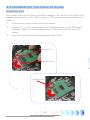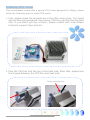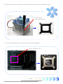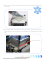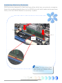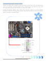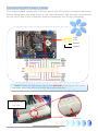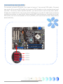
1
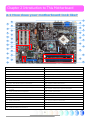
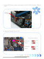
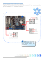
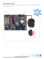
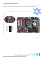
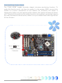
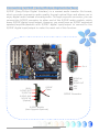
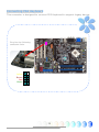
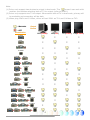
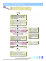
eTable of Contents eTable of Contents.................................................................................. 1 1.1 A Thank-you Note Before You Get Start..........................................................4 1.2 Features of This Manual ...............................................................................5 1.3 Safety Information ......................................................................................5 Chapter 2 Introduction to This Motherboard ............................................... 6 2.1 How does your motherboard look like?...........................................................6 2.2 Specification ...............................................................................................7 2.3 Block Diagram ............................................................................................8 Chapter 3 Hardware Installation ............................................................... 9 3.1 Quick Installation Procedure .........................................................................9 3.2 Installation You Have to Know..................................................................... 10 Installing CPU ...........................................................................................10 Installing CPU Cooler .................................................................................11 Installing CPU and System Fans ..................................................................15 Installing Memory Modules .........................................................................16 Maximum The Performance of the Dual Channel............................................17 Connecting IDE and Floppy Cables ..............................................................18 Connecting Front Panel Cable .....................................................................19 Connecting ATX Power Cables .....................................................................20 3.3 Other Installation for Your Reference ........................................................... 21 Setting CPU Voltage and Frequency .............................................................21 Connecting Serial ATA................................................................................22 Adjusting your Hard Disk Setting.................................................................23 Connecting PCI express x16 Graphics Slot ....................................................25 Connecting PCI Express x 1 Slot..................................................................27 Connecting IrDA........................................................................................28 10/100/1000Mbps LAN Supported ...............................................................29 1 Connecting USB2.0....................................................................................30 Connecting 1394 .......................................................................................31 Super 7.1 Channel Audio Effect ...................................................................32 Connecting Front Audio ..............................................................................33 Connecting CD_IN .....................................................................................34 Connecting COM1/COM2 ............................................................................35 Connecting Case Open ...............................................................................36 Connecting S/PDIF (Sony/Philips Digital Interface) ........................................37 Connecting PS2 Keyboard ..........................................................................38 Colored Coded Back Panel ..........................................................................39 LED Indication ..........................................................................................40 3.4 Jumper Settings ........................................................................................ 41 4.2 Other Useful Features ................................................................................ 42 Chapter 5 Setting BIOS......................................................................... 43 5.1 Introduction ............................................................................................. 43 5.2 How To Use Phoenix-Award™ BIOS Setup Program ........................................ 44 5.3 How To Enter BIOS Setup ........................................................................... 44 Standard CMOS Features ...........................................................................45 Advanced BIOS Features ............................................................................47 Advanced Chipset Features.........................................................................49 Integrated Peripherals ...............................................................................51 Power Management Setup ..........................................................................56 PNP/PCI Configurations ..............................................................................58 Silent BIOS/HW Monitor .............................................................................59 Frequency/Voltage Control .........................................................................60 Load Setup Defaults ..................................................................................61 Load Turbo Defaults ..................................................................................62 Set Password ............................................................................................63 Save & Exit Setup .....................................................................................63 2 Exit without Saving ...................................................................................63 Load EEPROM Defaults ...............................................................................63 Save EEPROM Defaults...............................................................................63 Credits.....................................................................................................63 5.4 BIOS Upgrade under Windows environment.................................................. 64 5.5 Vivid BIOS technology ............................................................................... 66 Chapter 6 Installing Drivers ................................................................... 67 6.1 Installing Drivers....................................................................................... 68 6.2 Installing Utilities ...................................................................................... 69 6.3 Display output behavior ............................................................................. 70 Display output behavior .............................................................................71 Chapter 7 Troubleshooting..................................................................... 73 Chapter 8 Technical Support .................................................................. 74 Model Name and BIOS Version....................................................................75 Register Your Motherboard .........................................................................75 Technical Support......................................................................................76 3 1.1 A Thank-you Note Before You Get Start First of all, we would like to express our gratitude for purchasing AOpen products. Once again, this motherboard is designed uniquely to meet all your personal needs with our great industry-designing ability and our everlasting perseverance to the quality of all our products. This manual will introduce you how this motherboard is installed. Please keep it well for your future reference. If you lost your printed manual, you may also go to our website at http://www.aopen.com to download the updated file. Now, we would like to invite you to personally experience this user-friendly manual and all of the powerful functions this AOpen product offers. The logos of Adobe and Acrobat are the registered trademarks of Adobe Systems Incorporated. The logos of AMD, Athlon, and Duron are the registered trademarks of Advanced Micro Devices, Inc. The logos of Intel, Intel Celeron, Pentium II, III, Pentium 4 and Pentium Mare the registered trademarks of Intel Corporation. The logos of nVidia are the registered trademarks of nVidia Corporation. The logos of Microsoft, Windows are the registered trademarks of Microsoft Corporation in America and other countries. All the titles of the products and the trademarks mentioned in this manual are for the purpose of illustrative conveniences and are possessed by their respective firms. We regret not informing about any changes in usage standards and other related information. AOpen reserves the right of altering or modifying the content of this manual. In case of any mistakes or incorrect descriptions, which include those on the products, AOpen makes no guarantee or commitments. This document is based on the copyright laws in order to protect our company and reserve all rights. Under no circumstances are any types of duplicating and loading this brochure in any databases and media permitted except the permission signed on formal document by AOpen Company. 1996-2005 Copyrights, AOpen Ltd. All rights reserved. 4 1.2 Features of This Manual To help you grab the useful information of this motherboard and aware of certain conditions that you might need to know, you will see the icons below frequently: Note This contains knowledge you should know in process of assembling, or some helpful tips. Warning / Caution Warning Please be careful when you see this mark. It highlights mistakes that occur often during assembling, or something you need to pay attention to. Tip Warning This tip tells you some useful information that will make your installation smoothly. 1.3 Safety Information Please wear a wrist strap and attach it to a metal part of the system unit before handling a component. Alternatively, you can also touch an object that is of ground connection or with metal surface. Always unplug the power before you make any jumper setting. Before you install or remove any components on the motherboard, please make sure to disconnect the power first in case of damaging motherboard or other components. 5 Chapter 2 Introduction to This Motherboard Chapter 2 Introduction to This Motherboard 2.1 How does your motherboard look like? 1 16 17 19 21 23 25 27 2 3 18 4 5 20 6 22 7 8 24 9 26 10 11 28 29 12 30 31 33 13 32 14 34 15 35 1. Power Temperature Connector 19. Printer Port connector 2. CD_IN Connector 20. JP28 PS2 KB/Mouse Wakeup Jumper 3. Marvell PCI-Express Gigabit LAN 21. 32-bits PCI Expansion Slot 4. Azalia Audio codec 5. S/PDIF Connector 23. DVI Controller 7307 6. ATX Power Connector 24. IrDA Connector 7. Front Audio Connector 25. TV-OUT Controller 7021 22. PCI Express VGA Card Enable Jumpers 8. 4-pin 12V ATX Power Connector 26. Power FAN Connector 9. PCI Express x16 Slot 10. 479-pin CPU socket supporting Intel Pentium M CPU 11. Intel 915G/ICH6 Chipsets 27. USB Connector 28. 1394 Controller Agere FW3226 12. CPU FAN Connector 30. Case Open Connector 13. System FAN1 Connector 31. JP14 Clear CMOS Jumper 14. 240-pins DIMMs x 4 (DDRII) 32. SYSTEM FAN2 Connector 15. IDE Connector 33. Front Panel Connector 16. PCI Express x1 Slot 34. FDD Connector 17. PS/2 Mouse & Keyboard Connector 35. Serial ATA Ports x 4 29. 1394 Connector 18. COM1/COM2 Connectors 6 2.2 Specification Here is the main function of your motherboard. Models CPU Chipset Main Memory Graphics IDE LAN Sound USB IEEE 1394 Slots Back Panel I/O On Board Connector BIOS Board Size i915Ga-HFS Intel Pentium M (Dothan) CPU Socket 479 533MHz Intel 915G/ICH6 Dual Channel DDRII DIMM x 4, DDRII400/533 DIMM Type : 256/512MB & 1GB Max Memory : 4GB Integrated VGA Engine in Chipset PCI Express x 16 Graphic Slot Integrated ATA100 and Serial ATA Controller Max Disk: 144,000,000GB [by 48 bits LBA Spec.] Marvell Gigabit PCI Express LAN Chip Intel High Definition Audio on Board Support 7.1 Channel and above Integrated in chipset, USB 2.0 x 8 Agere 1394 Control Chip PCI Express x16 Graphics Slot x 1 PCI Express x1 Slot x 1 PCI Slots x 3 USB Ports x 4, LAN Port x 1 VGA Port x 1, DVI Port x 1 Standard Video Port x 1 YPbPr Video Port x 1 D Connector (D1, D2, D3, D4) (For Japanese version only) Line_In x 1, Speaker_Out x 1, MIC_In x 1 Rear SUR x 1, Center/Subwoofer x 1, Side SUR x 1 Floppy Drive Connector x 1 IDE Channel: ATA100 x 1 Serial ATA Channel x 4 Front Panel x 1 Front Audio x 1 USB2.0 Connector x 2 CPU FAN x 1 System FAN x 2 Power FAN x 1 Power Temperature Connector x 1 Case Open Connector x 1 S/PDIF Connector x 1 CD_IN x 1 IrDA x 1 Printer Connector x 1 PS2 Keyboard Connector x 1 COM1 Connector x 1 COM2 Connector x 1 IEEE 1394 x 2 Award PnP 4Mb Flash ROM BIOS 305 mm x 220 mm 7 2.3 Block Diagram VGA Onboard Slot x 1 PCI Bus 533MHz Standard Video PCI Express x 1 500MB/s Socket 479 Intel Pentium M CPU 32-bit PCI Slot x 3 150MB/s Serial ATA Port x 4 System Bus 33/66/100 PCI Express x 16 Graphics Slot DVI Connector YPbPr Connector ATA Intel 915G Chipset Chrontel 7307 IDE Drives x 2 RealTek Azalia CODEC Chrontel 7021 DDRII DIMM x 4 ICH6 DDRII 400/533 RAM Up to 4GB 4Mbits Flash EEPROM Marvell PCI Express Gigabit LAN Chip USB Port x 8 Agere IEEE 1394 Controller LAN connect Component Parallel Port Floppy Disk Drive Winbond Super I/O Serial Port x2 8 IEEE 1394 x 2 Chapter 3 Hardware Installation Chapter 3 Hardware Installation 3.1 Quick Installation Procedure 12. Installing Drivers & Utilities 1. Installing CPU 11. Installing Operating System (such as, Windows XP) 2. Installing CPU Fan & System Fan 10. Loading Default BIOS, Setting CPU Frequency 3. Installing Memory Module 9. Connecting Back Panel Ports 4. Installing HD, CD-ROM and SATA Disk, etc 8. Installing Other Devices (USB, Front Audio, etc) 5. Connecting Front Panel Cable 7. Installing PCI Express x 16 Graphics Cards & PCI Express x 1 Cards and PCI Cards 6. Connecting ATX Power Cable 9 3.2 Installation You Have to Know Installing CPU This socket supports uFCPGA & uFCBGA package CPU, which is the latest CPU package developed by Intel. Other forms of CPU package are impossible to be fitted in. 1. Unscrew the socket screw counter-clockwise. 2. Locate Pin 1 in the socket and look for a golden arrow on the CPU upper interface. Match Pin 1 and golden arrow. Then insert the CPU into the socket. 3. Lock the CPU socket screw clockwise to fasten CPU. Socket Pin 1 Socket screw Golden arrow 10 Installing CPU Cooler This motherboard comes with a special CPU cooler designed by AOpen, please follow the following steps to install CPU cooler. 1. First, please check the all parts are in the CPU cooler’s box. You might get one thermal compound, two screws, CPU Fan, and the thermal heat sink. If you didn’t get any of them, please contact with local AOpen technical support team directly. 2. Plug the CPU Fan into the top of the heat sink. After that, please lock the screws between the CPU Fan and heat sink. Screw onto the hole 11 3. Remove the four screws of the heat sink and let the bracket drop. Remove CPU cooler Back Panel 4. Lock the bracket on the back of the motherboard. Put the bracket on it 12 5. Smear over the thermal compound under the heat sink smoothly and let it be well mixed. 6. Put the CPU cooler on the processor and lock the four screws of the heat sink. Please make sure the screws are well tied between the motherboard and heat sink. Screw onto the hole 13 7. Let the CPU Cooler’s power cord connect to the CPU FAN Connector. Then it’s done. CPUFAN Connector 8. Adjust the jumper for your CPU. Front Side Bus Frequency 14 Auto BY CPU 1 JP1 133MHz 1 JP1 DOTHAN Bx 1 JP2 Reserve 1 JP2 Installing CPU and System Fans Plug the CPU fan cable to the 3-pin CPU FAN connector. If you have chassis fan, you can also plug it in SYSFAN2 connector. --- GND +12V Sensor SYSFAN1 Connector GND +12V Sensor Sensor CPUFAN Connector +12V GND SYSFAN2 Connector Note: Some CPU fans do not have sensor pin so that they cannot support fan monitoring. 15 Installing Memory Modules DIMM slots are designed in black and navy blue which are very easy to recognize. Insert the module straight down to the DIMM slot with both hands and press down firmly until the DIMM module is securely in place. Tab Pin 1 Key Note: The tabs of the DIMM slot will clip to hold the DIMM in place when the DIMM touches the slot’s bottom. 16 Maximum The Performance of the Dual Channel To obtain the highest performance of Dual Channel, the configuration of DIMM must meet the following conditions. Matched DIMM configuration in each channel ● Same density (128MB~1GB) As long as you insert memory modules of same density into Channel 1 (DIMM1 & DIMM3) and Channel 2 (DIMM2 & DIMM4), dual channel mode will be enabled. DIMM1 + DIMM3 = DIMM2 + DIMM4 Ex: if you insert 1GB memory module into DIMM1 and DIMM3, dual channel mode will be enabled when DIMM2 + DIMM4 = 1GB ● Same DRAM bus width (x8 or x16) ● Either single-sided or double-sided Note: Using memory modules of different chip will cause system unstable. When dual channel mode is successfully enabled, the screen will show “Dual Channel Mode Enabled” while entering POST screens. 17 Connecting IDE and Floppy Cables Connect the 34-pin floppy cable and 40-pin, 80-wire IDE cable to floppy connector and IDE connector. Be careful of the pin1 orientation. Wrong orientation may cause system damage. Pin 1 FDD Connector Pin 1 Primary Slave (2nd) Primary Master (1st) ATA 33/66/100 IDE Connector 18 Connecting Front Panel Cable Attach the power LED, speaker and reset switch connectors to the corresponding pins. If you enable “Suspend Mode” item in BIOS Setup, the ACPI & Power LED will keep flashing while the system is in suspend mode. Locate the power switch cable from your housing, which is a 2-pin female connector from the housing front panel. Plug this connector to the soft-power switch connector marked SPWR. 1 NC NC +5V HDD LED HDD LED +5V +5V GND NC SPEAKER Power Switch GND Power LEDGND Power LED+ NC GND GND RESET GND Front Panel Connector 19 Connecting ATX Power Cables This motherboard comes with a 24-pin and 4-pin ATX power connector as shown below. Make sure you plug them in the right direction. We strongly recommend you to insert the 4-pin connector before connecting the 20-pin connector. +12V +12V Ground Ground Note: Please aim the power plug at the left side of the 24-pin ATX power connector when the foolproof design faces you as shown. Aiming at the left side Foolproof 20 3.3 Other Installation for Your Reference Setting CPU Voltage and Frequency Setting CPU Core Voltage This motherboard supports Voltage ID (VID) function to detect CPU voltage automatically during power-on. Setting CPU Frequency This motherboard is CPU jumper-less design, you can set CPU frequency through 1MHz stepping CPU Overclocking in the BIOS. CPU Core Frequency = CPU External Frequency x CPU Ratio. However, all CPU now selling in the market belong to "Fixed Multiplier". That means users can not adjust the CPU Ratio but only change CPU FSB clock to achieve overclocking. (Users do the overclocking at their own risk!!) BIOS Setup > Frequency / Voltage Control > CPU Bus Frequency CPU Ratio 4x, 7x… 17x, 18x, 20x CPU FSB (Adjustment manually) FSB = 100MHz - 400MHz by 1MHz Stepping CPU Overclocking Processor Number Architecture Clock Speed Front Side Bus Cache Ratio Pentium M 770 90nm 2.13GHz 533MHz 2MB L2 16x Pentium M 760 90nm 2.00GHz 533MHz 2MB L2 15x Pentium M 750 90nm 1.86GHz 533MHz 2MB L2 14x Pentium M 740 90nm 1.73GHz 533MHz 2MB L2 13x Pentium M 730 90nm 1.60GHz 533MHz 2MB L2 12x Pentium M 765 90nm 2.10GHz 400MHz 2MB L2 21x Pentium M 755 90nm 2.00GHz 400MHz 2MB L2 20x Pentium M 745 90nm 1.80GHz 400MHz 2MB L2 18x Pentium M 735 90nm 1.70GHz 400MHz 2MB L2 17x Pentium M 725 90nm 1.60GHz 400MHz 2MB L2 16x Pentium M 715 90nm 1.50GHz 400MHz 2MB L2 15x Pentium M 705 130nm 1.50GHz 400MHz 1MB L2 15x Celeron M 370 90nm 1.50GHz 400MHz 1MB L2 15x Celeron M 360 90nm 1.40GHz 400MHz 1MB L2 14x Celeron M 350 90nm 1.30GHz 400MHz 1MB L2 13x Celeron M 340 130nm 1.50GHz 400MHz 512KB L2 15x Celeron M 330 130nm 1.40GHz 400MHz 512KB L2 15x Note: With CPU speed changing rapidly, there might be faster CPU on the market by the time you received this installation guide. This table is kindly for your references only. Warning: Intel 915G chipset support maximum 533MHz (133MHz*4) system bus; higher clock setting may cause serious system damage. 21 Connecting Serial ATA To connect a serial ATA disk, you have to have a 7-pin serial ATA cable. Connect two ends of the serial ATA cable to the serial ATA header on the motherboard and the disk. Like every other traditional disk, you also have to connect a power cable. Please be noted that it is a jumper free implement; you don’t need to set jumpers to define a master or slave disk. When serial ATA hard disks are installed on serial ATA ports, the one connected on Port0 (SATA1) will be set as the first boot device automatically. SATA1 SATA2 SATA3 SATA4 22 Adjusting your Hard Disk Setting Except its original 1 set of parallel IDE, this motherboard supports the latest serial ATA hard disk. If you are unable to find your newly installed serial ATA hard disks on your operating system after having them installed, the problem may lie in the BIOS setting. You can simply adjust BIOS settings to have them work properly. After installing your hard disks properly, you can directly go to BIOS setting screen for adjustment. Simply pressing “Integrated Peripherals Æ OnChip IDE Device Æ On-Chip Serial ATA” to choose your preferable mode. If you have no intention of changing its original setting, the default would be Auto. 23 If you desire to change the default setting, press Enter for selection list: Disabled: You can choose this item if there are only traditional IDE hard disks had been installed on your system. Disabling this item will also cancel the detection of serial ATA hard disks during POST, which will theoretically speed up your boot-up time a little bit; however, please remember to re-adjust the setting here if you want to use serial ATA hard disk later. Auto: This is factory default setting on this motherboard. Basically, if your system functions properly, it is no necessary to change it. The system will automatically recognize PATA (IDE) as primary.. Combined Mode: If you have traditional IDE hard disks and serial ATA hard disks installed at the same time, then you can choose this mode. Under this mode, you can randomly choose either IDE hard disks or serial ATA had disk as your first boot device. But please note, IDE will exist with serial ATA in a mapping way, which means it will occupy one of the serial Channel and leave you one serial Channel only. When PATA Mode is set to primary, SATA3 and SATA4 will be set to secondary, and when PATA Mode is set to secondary, SATA1 and SATA2 will be set to primary. Enhanced Mode: If you are using the latest operating system (say, Windows XP, Windows.NET Server), it is highly recommended that you select Enhanced Mode. Under this mode the system will detect all six devices (traditional IDE x 2, Serial ATA x 4) completely and function perfectly. But please note that PATA Mode is set to primary under this mode. Note: According to practical lab tests of us, there are no obvious problems or mistakes happened when we set this mode under Windows2000 operating system; however, it is not recommended by Intel. SATA Only: You may select this mode if you install serial ATA hard disks only. 24 Connecting PCI express x16 Graphics Slot This motherboard provides a PCI Express x 16 Graphics slot, a black slot having the latest PCI Express x 16 specification on motherboard. The PCI Express x 16 is a bus interface targeted for high-performance 3D graphic. Traditionally AGP used both rising and falling edge of the 66MHz clock for 8X AGP, and the data transfer rate could achieve 2.1GB/s. Now PCI Express x 16 is moving to higher data transfer rate, which is upgraded to 8.0GB/s (250MB/s x 16 x 2, it’s 4.0GB/s per direction).. JP3 ~ JP12 PCIex16 JP3 JP4 JP5 JP6 JP7 JP8 JP9 JP10 JP11 JP12 HDTV On On On On On On On On On On PCIeX16 Off Off Off Off Off Off Off Off Off Off 25 If user plugs a PCI Express x 16 Graphics, you must remove jumpers beside PCI Express x 16 Slot. Remove Jumper Warning: If user doesn’t remove jumper, it might make system unstable. 26 Connecting PCI Express x 1 Slot This motherboard provides one PCI Express x 1 slot, which is located between the PCI Express x 16 and traditional PCI slot. In order to go with the step of today’s and tomorrow’s processors, PCI Express x 1 provides higher I/O bandwidth. The transfer data rate could achieve 500MB/s concurrently (it’s 250MB/s per direction), which is nearly 4 times faster than the traditional PCI. You could install any PCI Express x 1 device in these slots for your preference. PCIex1 27 Connecting IrDA The IrDA connector can be configured to support wireless infrared module, with this module and application software such as Laplink or Windows Direct Cable Connection, user can transfer files to or from laptops, notebooks, PDA devices and printers. This connector supports both HPSIR (115.2Kbps, 2 meters) and ASK-IR (56Kbps). Install an infrared module onto the IrDA connector and enable the infrared function from BIOS Setup, UART Mode, you can use this function. Please make sure you connect correct orientation when plugging IrDA module. Pin 1 1 NC +5V IR_TX KEY GND IR_RX IrDA Connector 28 10/100/1000Mbps LAN Supported On the strength of Marvell Gigabit LAN controller on board, this motherboard provides 10/100/1000Mbps Ethernet for office and home use. The Ethernet RJ45 connector is located on the top of USB connectors. The right hand side LED indicates link mode; it lights in yellow when linking to network. The left hand side LED indicates the transfer mode and will light in green when data is transferring at 100Mbps (never lights while at 10Mbps), but will light in orange when transferring in Gigabit’s mode. To enable or disable this function, you may simply adjust it through BIOS. To enable LAN wakeup function, you have to set the “Wake on PCI Card” enable in the BIOS “Power Management Setup” section. Speed LED (Left) Green 100Mbps Orange Gigabit mode ACT LED (Right) Yellow 29 Connecting USB2.0 This motherboard provides eight USB 2.0 ports to connect USB devices such as mouse, keyboard, modem, printer, etc. There are four ports on the back panel. You can use proper cables to connect Front USB connector to USB modules or chassis front panel. Pin 1 Pin 1 30 Connecting 1394 With IEEE1394 Chip on board (AGERE 1394), having its data transfer rate up to 400Mb/s, this interface can connect to devices that require high data transferring performance such as digital camera, scanner or others IEEE 1394 devices. Please use appropriate cables to connect IEEE1394 devices. Pin1 Pin1 SHIED GND +12V (Fused) +12V (Fused) TPB+ GND TPA+ TPBGND TPA2 1 IEEE 1394 Connector Warning: Please note that Hot-Plug is not allowed on IEEE 1394 headers; doing so will burn the controller IC and damage the motherboard. 31 Super 7.1 Channel Audio Effect This motherboard comes with an ALC880 CODEC, which supports the latest 7.1 Channel with high quality of audio effects, bringing you a brand new audio experience. This motherboard provides 7.1 Channel ports shown as below. Picture represents the standard location of all speakers in 7.1 Channel sound tracks. Please connect the plug of your front speakers to the green “Speaker out” port , rear surround speakers to orange port, side surround speakers to gray port and both of the center and subwoofer speakers to black port on the back panel. 32 Connecting Front Audio If the housing is designed with an audio port on the front panel, you’ll be able to connect onboard audio to front panel through this connector. By the way, please remove the jumper cap from the Front Audio Connector before you connect the cable. Do not remove this yellow jumper cap if your housing doesn’t have an audio port on the front panel. Pin1 1 AUD_MIC AUD MIC BIAS AUD_FPOUT_R NC AUD_FPOUT_L AUD_GND AUD_VCC AUD_RET_R KEY AUD_RET_L Front Audio Connector 33 Connecting CD_IN This connector is designed to connect CD Audio cable from CDROM or DVD drive to onboard sound. L GND GND R CD-IN Connector 34 Connecting COM1/COM2 This motherboard provides two serial ports. All of them are on the left of PCI32 slot. With proper cable, you can connect it to the back panel of chassis. Pin 1 Pin 1 1 1 DCD# SOUT GND RTS# R1# SIN DTR# DSR CTS# 35 Connecting Case Open The “CASE OPEN” header provides chassis intrusion-monitoring function. To make this function work, you have to enable it in the system BIOS, connect this header to a sensor somewhere on the chassis. So, whenever the sensor is triggered by lights or by the opening of the chassis, the system will beep to inform you. Please be informed that this useful function only applies to advanced chassis; you may purchase an extra sensor, attach it on your chassis and make a good use of this function. Pin 1 1 Sensor GND Chassis Intrusion Connector 36 Connecting S/PDIF (Sony/Philips Digital Interface) S/PDIF (Sony/Philips Digital Interface) is a newest audio transfer file format, which provides impressive audio quality through optical fiber and allows you to enjoy digital audio instead of analog audio. Through a specific converter, you can connect the S/PDIF connector to other end of the S/PDIF audio module, which bears S/PDIF digital input/output. However, you must have an S/PDIF supported speaker/amplifier/decoder with S/PDIF digital input/output to connect to the S/PDIF digital input/output to make the most out of this function. Pin 1 5 (RCA) S/PDIF OUT S/PDIF IN S/PDIF Cable SPDIF IN GND SPDIF OUT KEY +5V 1 S/PDIF Connector S/PDIF OUT S/PDIF IN (Optical) S/PDIF Module (User Upgrade Optional) 37 Connecting PS2 Keyboard This connector is designed to connect PS2 Keyboard to support legacy device. Plug into by following connector color Yellow Brown Red Green 1 38 Colored Coded Back Panel The onboard I/O devices have AC’97 sound, VGA Port, DVI Connector, YPbPr Connector, S-Video, RJ-45 LAN Connector and USB Port. The view angle of drawing shown here is from the back panel of the housing. Line-In Rear SUR VGA Port Y Center/ Subwoofer Pb Pr Speaker Out RJ45 LAN Jack Side SUR MIC-In DVI Connector S-Video D Connector (Japanese Only) USB 2.0 Ports Line-In : Comes from the signal sources, such as CD/Tape player. Rear SUR: For rear surround speaker. Center/Subwoofer: For center & subwoofer speaker. Speaker Out: To External Speaker, Earphone or Amplifier. Side SUR: For side surround speaker. MIC-In: For Microphone. VGA Connector: To connect with PC monitor. DVI Connector: To connect with monitor which support DVI input. YPbPr Connector: To connect with TV which support YPbPr input. Standard Video : To connect with TV which support SVideo input. RJ-45 LAN Port: To connect Ethernet for home or office use. USB Port: Available for connecting USB devices. 39 LED Indication LED indication including Standby LED and BOOT LED are AOpen’s considerate designs that aim at providing you friendly system information. STBY LED will light up when power is provided to the motherboard, giving you a convenient indication check the system power status in circumstances such as power on/off, stand-by mode and RAM power status during Suspend to RAM mode. BOOT LED will keep blinking when you power the system on and when your system is under POST (Power-On Self Test). After POST diagnoses everything all right and finishes the booting, the LED will stay on otherwise it will remain flashing to warn you that mistakes have occurred during POST. BOOT LED STBY LED 40 3.4 Jumper Settings This motherboard provides PS2 keyboard / mouse wake-up function. JP28 Keyboard / Mouse Wakeup Jumper 1 Disable (Default) 1 Enable JP28 PS2 KB/Mouse Wakeup Jumper 1 1 Normal (Default) Clear CMOS JP14 Clear CMOS Jumper You can clear CMOS to restore system default setting. To clear the CMOS, follow the procedure below. JP14 Clear CMOS Data 1. Turn off the system and unplug the AC power. 2. Remove ATX power cable from connector PWR2. 3. Locate JP14 and short pins 2-3 for a few seconds. 4. Return JP14 to its normal setting by shorting pin 1 & pin 2. 5. Connect ATX power cable back to connector PWR2. 41 Chapter 4 Special Features and Utilities Chapter 4 Special Features and Utilities 4.2 Other Useful Features With excellent design ability of R&D team, AOpen boasts for its various powerful and handy features that come with our product like follows. You are welcomed to visit our technical website to learn more about those features. http://english.aopen.com.tw/tech/techinside 42 Chapter 5 Setting BIOS Chapter 5 Setting BIOS 5.1 Introduction System parameters can be modified by going into BIOS Setup menu; this menu allows you to configure the system parameters and save the configuration into the 128 bytes CMOS area (normally in the RTC chip or in the main chipset). The Phoenix-Award BIOS™ that installed in the Flash ROM of the motherboard is a custom version of an industry standard BIOS. The BIOS provides critical low-level support for standard devices such as hard disk drives, serial and parallel ports. AOpen’s R&D engineering team had optimized most BIOS settings of this motherboard. However, some default settings of BIOS cannot fine-tune those sections that controlled by chipset. Therefore, this chapter is intended to guide you and help you to configure some other settings. To enter BIOS setup menu, press <Del> when POST (Power-On Self Test) screen is shown on your monitor. Note: Because BIOS code is the most often changed part on motherboard, the BIOS information contained in this manual may be different from the BIOS version that comes with your motherboard. 43 5.2 How To Use Phoenix-Award™ BIOS Setup Program Generally, you can use arrow keys to highlight items that you want to choose, press <Enter> key to select, and use <Page Up> and <Page Down> keys to change setting values. You can press <Esc> key to quit Phoenix-Award™ BIOS setup program. The following table provides details about how to use keyboard in the Phoenix-AwardBIOS setup program. Key Description Page Up or + Change setting to next value or increase the value. Page Down or - Change setting to previous value or decrease value. Enter Select the item. Esc Up Arrow In main menu: Quit without saving any changes. In sub menu: Exit current menu to main menu. Highlight previous item. Down Arrow Highlight next item. Left Arrow Move the light bar to left side of menu. Right Arrow Move the light bar to right side of menu. F6 Load Setup Default setting value from CMOS. F7 Load turbo setting value from CMOS. F10 Save changed settings and exit setup program. 5.3 How To Enter BIOS Setup After finishing the jumper settings and connecting cables, you can power on and enter the BIOS Setup. Press <Del> during POST (Power-On Self Test) and choose "Load Setup Defaults" for recommended optimal performance. Del Warning: Please avoid of using “Load Turbo Defaults”, unless you are certain your system components (CPU, SDRAM, HDD, etc.) are good enough for turbo setting. 44 Standard CMOS Features The "Standard CMOS Setup" sets the basic system parameters such as the date, time, and the hard disk type. Use the arrow keys to highlight an item and <PgUp> or <PgDn> to select the value for each item. Standard CMOS Features > Date To set the date, highlight the Date parameter. Press <PgUp> or <PgDn> to set the current date. The date format is month, date, and year. Standard CMOS features > Time To set the time, highlight the Time parameter. Press <PgUp> or <PgDn> to set the current time in hour, minute, and second format. The time is based on the 24 hour military clock. Standard CMOS features > Primary Master Standard CMOS features > Primary Slave Standard CMOS features > Secondary Master Standard CMOS features > Secondary Slave This item lets you select the IDE hard disk parameters that your system supports. These parameters are Size, Number of Cylinder, Number of Head, Start Cylinder for Pre-compensation, Cylinder number of Head Landing Zone and Number of Sector per Track. The default setting is Auto, which enables BIOS to automatically detect the parameters of installed HDD (Hard Disk Drive) at POST (Power-On Self Test). If you prefer to enter HDD parameters manually, select Manual. 45 IDE HDD Auto-Detection: Press “Enter” to auto-detect parameters of HDD IDE Channel 0 Master (Slave): Define the parameters of IDE devices in Channel 0 (Master or Slave). Available options: z None: if there is no device, please select “None” for speeding boot up. z Auto: enable BIOS to auto-detect parameters of IDE device. (Default) z Manual: allow users to define parameter of IDE device. Access Mode: Set the using mode of HDD. Available options: CHS / LBA / Large / Auto (default). User can select the mode according to the label on HDD. Cylinder: Enter cylinder number Head: Enter head number Precomp: Write precompensation Landing Zone: Location of head Sector: Sector Number Standard CMOS features > Drive A This item allows user select the floppy drive type. Available items: None / 360KB 5.25” / 1.2MB 5.25” / 720KB 3.5” / 1.44MB 3.5” / 2.88MB 3.5” Standard CMOS features > Vedio This item specifies the type of video card in use. The default setting is VGA/EGA. Since current PCs use VGA only, this function is almost useless and may be disregarded in the future. Standard CMOS features > HaltOn This parameter enables you to control the system stops in case of Power-On Self Test (POST) error. Available items: No errors / All errors / All, But Keyboard / All, But Diskette / All, But Disk/Key 46 Advanced BIOS Features This screen appears when you select the option "Advanced BIOS Features" from the main menu. Advanced BIOS Features > CPU feature Delay Prior to Thermal: Select delay time periods prior to enabling the Thermal Monitor. Available options: 4 Min / 8 Min / 16 Min / 32 Min Thermal Management: Set the function of CPU internal Thermal Management. When CPU supports Thermal Monitor 1 (TM1) and Thermal Monitor 2 (TM2), user could select TM1 or TM2. But if CPU doesn’t Support TM2, it will be fixed On TM1. When TM2 is enabled, and a high temperature situation is detected, it will cause the CPU to adjust its operating frequency via the core to bus ratio and input voltage via the VID signals. TM2 Bus Ratio and TM2 Bus VID show the CPU default value for TM2. 47 Advanced BIOS Features > Removable Device Priority Advanced BIOS Features > Hard Disk Boot Priority Advanced BIOS Features > CD-ROM Boot Priority This parameter allows you to specify the system boot up search sequence. Advanced BIOS Features > First Boot Device Advanced BIOS Features > Second Boot Device Advanced BIOS Features > Third Boot Device This parameter allows you to specify the system boot up search sequence. Available options: z Removable: Floppy, USB, ZIP…etc z Hard Disk: Hard Disk Drives z CD-ROM: CD-ROM, DVD-ROM…etc z LAN: LAN Card with boot ROM z Disabled: Advanced BIOS Features > Boot Other Device This parameter allows you to enable other system boot up devices that is not described above. Advanced BIOS Features > Boot Up NumLock Status Set this parameter to “On” to enable the numeric function of the numeric keypad. Set this parameter to “Off” to disabling the numeric function allows you to use the numeric keypad for cursor control. Advanced BIOS Features > Security Option The “System” option limits access to both the System boot and BIOS setup. A prompt asking you to enter your password appears on the screen every time you boot the system. The “Setup” option limits access only to BIOS setup. To disable the security option, select Password Setting from the main menu, don't type anything and just press <Enter> Advanced BIOS Features > HDD S.M.A.R.T Capability This item allows user to enable S.M.A.R.T. (Self-Monitoring Analysis & Reporting Technology) capability for HDD. This function could predict the possibility of HDD failure. The default is “Disabled”. Advanced BIOS Features > Show Logo On Screen This item allows user to select to show or hide “Full Screen logos” or “Vivid BIOS logos”. Advanced BIOS Features > Bypass Vivid BIOS This item allow user to bypass Vivid BIOS or not when booting up. 48 Advanced Chipset Features The "Advanced Chipset Features" includes settings for the chipset dependent features. These features are related to system performance. Warning: Make sure you fully understand the items contained in this menu before you try to change anything. You may change the parameter settings to improve system performance. However, it may cause your system to be unstable if the setting is not correct for your system configuration. Advanced Chipset features > DRAM Timing Selectable Available options: z By SPD: System will define timing according to default of Dram. (Default) z Manual: Allow user to define timing himself. Advanced Chipset features > CAS Latency Time When synchronous DRAM is installed, the number of clock cycles of CAS latency depends on the DRAM timing. Available options: 2, 2.5, 3 Advanced Chipset features > DRAM RAS# to CAS# Delay This field lets user to insert a timing delay between the CAS and RAS strobe signals, used when RAM is written to, read from, or refreshed. Fast gives fater performance; and Slow give more stable performance. This field applies only when synchronous DRAM is installed in the system. Available options: 2, 3, 4, 5 49 Advanced Chipset features > DRAM RAS# Precharge If an insufficient number of cycles are allowed for the RAS to accumulate its charge before DRAM refresh, the refresh may be incomplete and the DRAM may fail to retain data. Fast give faster performance; and Slow gives more stable performance. This field applies only when synchronous DRAM is installed in the system. Available options: 2, 3, 4, 5 Advanced Chipset features > Active to Precharge Delay Select the operating system that is active to precharge delay. Available options: 4, 5, 6, 7, 8, 9, 10, 11, 12, 13, 14, 15 Advanced Chipset features > System Memory Frequency This item is used to set DRAM timing. Available options: DDR: 333 MHz, DDRII400 MHz, 533 MHz Advanced Chipset features > System BIOS cacheable Allow the system BIOS to be cached to allow faster system performance. Available options: Disabled, Enabled Advanced Chipset features > Video BIOS cacheable Allow the video BIOS to be cached to allow faster video performance. Available options: Disabled, Enabled Advanced Chipset features > Intruder Detection This item allow user to detect the housing is opened or not. It works only when the housing is designed with CASE OPEN cable and connected to motherboard. Available options: Disabled, Enabled Advanced Chipset features > PEG/On Chip VGA Control This item is used to select display first from onboard VGA or PCI ExpressGraphic card. Advanced Chipset features > Boot Display This item is used to set booting display. Available options: Auto, CRT, TV, EFP Advanced Chipset features > Init Display First If you installed a PCI VGA card, this item lets you decide which one is the initial display card. Advanced Chipset features > On-Chip Video Memory Size This item allows user to control the on-chip frame buffer size, fixed memory size, DVMT. Advanced Chipset features > On-Chip Frame Buffer Size Advanced Chipset features > FIXED Memory Size Advanced Chipset features > DVMT Memory Size 50 Advanced Chipset features > TV Format Available options: Auto, NTSC_M, NTSC_M_J, NTSC_433, NTSC_N, PAL_B, PAL_G, PAL_D, PAL_H, PAL_I, PAL_M, PAL_N, PAL_60, SECAM_L, SECAM_L1, SECAM_B, SECAM_D, SECAM_G, SECAM_H, SECAM_K, SECAM_K1. Advanced Chipset features > Delayed PWROK Signal This item is used to add the compatibility between motherboard and power supply for avoiding booting up failed. Available options: 400ms (default) / 300ms / 200ms /100ms / Disabled Integrated Peripherals This submenu appears if you select the option "Integrated Peripherals" from the main menu. This option allows you to configure the I/O features. 51 Integrated peripherals > OnChip IDE Device Integrated peripherals > OnChip IDE Device > On-Chip Serial ATA This item allows you to select work mode between SATA and PATA . Available options: Disabled: Disabled SATA Controller Auto: Auto arrange by BIOS Combined Mode: PATA and SATA are combine. Max. of 2 IDE drives in each channel. Enhanced Mode: Enable both SATA and PATA. Max. of 6 IDE drives are supported. SATA only: SATA is operating in legacy mode.. Integrated peripherals > OnChip IDE Device > PATA IDE Mode When On-chip SATA is selected to ”Combined Mode” , this item allows you to set PATA to primary or secondary. Integrated peripherals > OnChip IDE Device > SATA Port Integrated peripherals > OnChip IDE Device > On-Chip PATA Setting This parameter allows you to “Enable” or “Disable” the IDE device connected to the primary or secondary IDE connector. 52 Integrated peripherals > SuperIO Device This item allows you to set SuperIO device. Power ON Function: This item is used to select Wake on Keyboard/Mouse mode. z Any Key: This function allows you wake up the system by clicking any key. z Button Only: Disable Wake on KB/MS function. You can boot up your system by power button only. z Keyboard 98: If selecting this option, you can boot up the system by power button and the “Wake” key on Keyboard 98. z Password: Disable the function of power button and let the system can only be powered on through the preset keys (like a password). z Hot Key: If selecting this option, you also need to specify the hot key from “Hot Key Power On” item. z Mouse Left: This function allows you wake up the system by clicking left mouse button twice successively. z Mouse Right: This function allows you wake up the system by clicking right mouse button twice successively. Note: Whenever you change this item, it will only take effect after you restart the system and successfully boot the Windows or DOS. Wake on Mouse function applies to PS/2 mouse only. If you set a password but forget it, please clear CMOS. If you want to use Wake on Mouse function in DOS, it is necessary to install the DOS driver of the mouse. 53 KB Power ON Password: You can specify 1-5 keys as a password. Hot Key Power On: If you select “Hot Key” option in “Power On Function” Item, you need to specify a hot key here. Onboard FDC Controller: Setting this parameter to “Enabled“ allowing you to connect your floppy disk drives to the onboard floppy disk connector instead of a separate controller card. Change the setting to Disabled if you want to use a separate controller card. Onboard Serial Port 1: This item allows you to assign address and interrupt for the board serial port. The default is “Auto”. Onboard Serial Port 2: This item allows you to assign address and interrupt for the board serial port. The default is “Auto”. UART Mode Select: This item is configurable only if the "Onboard Serial Port 2" is enabled. This allows you to specify the mode of serial port2. Available options: z Normal: Sets serial port 2 to operate in normal mode. This is the default setting. z IrDA (SIR): This setting allows infrared serial communication at a maximum baud rate of 115.2K baud. z ASKIR: This setting allows infrared serial communication at a maximum baud rate of 57.6K baud. RXD, TXD Active: This item is used to select RxD (Receive Data) and TxD (Transmit Data) mode for UART, for instance, IR device, modem, etc. Normally, we suggest you keep the default setting. Please see the documentation that comes with your device. Available options: Hi, Hi / Hi, Lo IR Transmission Delay: If “Enabled” is selected, there will be a 4 character delay when SIR is changed from TX mode to RX mode. Onboard Parallel Port: This item controls the onboard parallel port address and interrupt. Available options: 3BC/IRQ7, 3BC/IRQ7, 3BC/IRQ7, Disabled Parallel Port Mode: This item lets you set the parallel port mode. The mode options are SPP (Standard and Bidirection Parallel Port), EPP (Enhanced Parallel Port) and ECP (Extended Parallel Port). Available options: z SPP (Standard and Bidirection Paralell Port): SPP is the IBM AT and PS/2 compatible mode. z EPP (Enhanced Parallel Port): EPP enhances the parallel port throughput by directly writing/reading data to/from parallel port without latch. z ECP (Extend Parallel Port): ECP supports DMA and RLE (Run Length Encoded) compression and decompression. z ECP + EPP EPP Mode Select: This item lets you select EPP mode protocol. Available options: EPP 1.7, EPP 1.9 54 ECP Mode Use DMA: This item lets you set the DMA channel of ECP mode. Available options: 3, 1 AC Power Auto Recovery: A traditional ATX system should remain at power off stage when AC power resumes from power failure. This design is inconvenient for a network server or workstation, without an UPS, that needs to keep power-on. This item is used to solve this problem. Selecting On enabling system to automatically power-on after AC power resumes; in the other hand, the system will remain power-off if you select Off. If Former-Sts (former status) option is selected, the system will power-on or power-off based on the original state. Available options: Former-Sts, On, Off Integrated peripherals > USB Controller: This item lets you enable or disable the USB controller. Integrated peripherals > USB 2.0 Controller: This item lets you enable or disable the USB 2.0 controller. Integrated peripherals > USB Keyboard Support: This item lets you enable or disable the USB keyboard driver within the onboard BIOS. The keyboard driver simulates legacy keyboard command and let you use USB keyboard during POST or after boot if you don't have USB driver in the operating system. Integrated peripherals > On Board Audio Codec: This item is used to enable or disable the onboard audio. Integrated peripherals > Onboard 1394 Control: This item lets you enable or disable onboard 1394. Integrated peripherals > Onboard LAN1 Control: This item lets you enable or disable onboard LAN. 55 Integrated peripherals enable or disable onboard Integrated peripherals enable or disable onboard > Onboard LAN2 Control: This item lets you LAN. > Onboard SATA Control: This item lets you SATA. Power Management Setup The Power Management Setup screen enables you to control the motherboard green features. See the following screen. Power Management > ACPI Suspend Type This function allows you to select suspend types. S1 is Power On Suspend and S3 is Suspend to RAM. Available Options: S1, S3, S1 & S3 Power Management > Soft-off by PWR-BTTN This is a specification of ACPI and supported by hardware. When Delay 4 sec. is selected, the soft power switch on the front panel can be used to control power On, Suspend and Off. If the switch is pressed for less than 4 seconds during power On, the system will go into Suspend mode. If the switch is pressed for longer than 4 seconds, the system will be turned Off. The default setting is Instant-Off. If Instant-Off is selected the soft power switch is only used to control On and Off, so there is no need to press it for 4 seconds, and there is no Suspend. Available Options: Delay 4 sec., Instant-Off Power Management > Wake On PCI card This is a function of PCI specification 2.2. PCI bus supports standby current to PCI card and PCI card can wakeup system if it detects certain activity. Available options: Disabled, Enabled 56 Power Management > Wake On Modem This option lets you specify enable or disable Wake On Modem function. Available options: Disabled, Enabled Power Management > Wake On RTC Timer The Wake Up Timer is more like an alarm, which wakes up and powers on your system at a pre-defined time for a specific application. It can be set to wake up everyday or on specific date within a month. The date/time is accurate to within a second. This option lets you enable or disable the RTC Wake Up function. Available options: By Date, By Week, Disabled Power Management > Date (of Month) Alarm This item is displayed when you enable the Wake On RTC Timer option. Here you can specify what date you want to wake up the system. For Example, setting to 15 will wake up the system on the 15th day of every month. Tip: Setting this item to 0 will wake up the system on the specified time (which can be set in the Wake On RTC Timer) every day. Power Management > Time (hh:mm:ss) Alarm This item is displayed when you enable the Wake On RTC Timer option. Here you can specify what time you want to wake up the system. 57 PNP/PCI Configurations The PNP / PCI Configuration Setup allows you to configure the ISA and PCI devices installed in your system. The following screen appears if you select the option "PNP/PCI Configuration Setup" from the main menu. PNP/PCI Configurations > Assign IRQ For VGA In case conflict occurs after you assign the IRQs or after you configure your system, you can enable this function, allow your system to automatically reset your configuration and reassign the IRQs, DMAs, and I/O address. Available options: Disabled, Enabled PNP/PCI Configurations > Assign IRQ For USB In case conflict occurs after you assign the IRQs or after you configure your system, you can enable this function, allow your system to automatically reset your configuration and reassign the IRQs, DMAs, and I/O address. Available options: Disabled, Enabled PNP/PCI Configurations > Maximum Payload Size This item allows you to set TLP (Transaction Layer Package) size. Available options: 128, 256, 512, 1024, 2048, 4096 58 Silent BIOS/HW Monitor This submenu displays Silent BIOS / HW monitor status and provides some basic control function. Silent BIOS/HW Monitor > CPU Warning Temperature This item is used to specify a CPU warning temperature. When the CPU’s temperature is higher than this predefined value, the CPU’s speed will automatically slow down and there will be a warning from BIOS. Silent BIOS/HW Monitor > Fan Mode This item allows user to select the mode of Fan Speed. Available options: z Full Speed: All fans will operate in full speed. 1. If CPUFAN doesn’t be connected or operate, there would be Warning Beep. 2. When SystemFAN or PowerFAN is connected to motherboard, if SystemFAN or PowerFAN doesn’t work, there would be Warning Beep. z Smart Control: User could set critical temperature for each fan. If the temperature is under critical temperature, fan wouldn’t operate; on the contrary fan would operate. 1. If Power Temperature connector isn’t be connected, Smart Control.mode for Power Fan will be disabled. z Fixed Speed: User could define the voltage of each fan to make fan operate in a fixed speed. 1. If CPUFAN doesn’t be connected or operate, there would be Warning Beep. 2. When SystemFAN or PowerFAN is connected to motherboard, if SystemFAN or PowerFAN doesn’t work, there would be Warning Beep. 59 Frequency/Voltage Control This submenu allows you to configure the CPU and memory clock. Frequency/Voltage Control > CPU Bus Frequency This item allows user to overclock the bus frequency of CPU. The range is from 100 to 400. Tip: When you fail to overclock, you could: Clear CMOS (JP14) to restore the default setting. After turning power on, press “Home” immediately until the screen appears. Frequency/Voltage Control > Clock Spread Spectrum This item is used to set the value of clock Spread Spectrum. BIOS will determine the adjustable value according to the CPU installed, not all items will be showed. This function only works when CPU Bus frequency is at 100MHz. Available options: 0.70% Center / 1.00% Center / 1.20% Center / Spread Off Frequency/Voltage Control > CPU Voltage Default This item shows the default voltage of the CPU installed. Frequency/Voltage Control > CPU Voltage Setting This item allows user to adjust CPU Vcore voltage, BIOS will determine the adjustable value according to the CPU installed. Frequency/Voltage Control > N/B Voltage Setting This item allows user to adjust North Bridge voltage, BIOS will determine the adjustable value according to the North Bridge default. 60 Load Setup Defaults The "Load Setup Defaults" option loads optimized settings for optimum system performance. Optimal settings are relatively safer than the Turbo settings. All the product verification, compatibility/reliability test report and manufacture quality control are based on "Load Setup Defaults". We recommend using these settings for normal operation. "Load Setup Defaults" is not the slowest setting for this motherboard. If you need to verify an unstable problem, you may manually set the parameter in the "Advanced BIOS Features" and "Advanced Chipset Features" to get slowest and safer setting. 61 Load Turbo Defaults The "Load Turbo Defaults" option gives better performance than "Load Setup Defaults". It is provided for the convenience of power user who wants to push the motherboard to get better performance. Turbo setting does not go though all the detail reliability and compatibility test, it is tested only with limited configuration and loading (for example, a system that contains only a VGA card and one DIMM/RIMM). Use Turbo setting only when you fully understand the items in Chipset Setup menu. 62 Set Password Password prevents unauthorized use of your computer. If you set a password, the system prompts for the correct password before boot or access to Setup. To set a password: 1. 2. 3. At the prompt, type your password. Your password can be up to 8 alphanumeric characters. When you type the characters, they appear as asterisks on the password screen box. After typing the password, press. At the next prompt, re-type your password and press again to confirm the new password. After the password entry, the screen automatically reverts to the main screen. To disable the password, press “Enter” when being prompted to enter the password. The screen displays a message confirming that the password has been disabled. Save & Exit Setup This function automatically saves all CMOS values before leaving Setup. Exit without Saving Use this function to exit Setup without saving the CMOS value changes. Do not use this option if you want to save the new configuration. Load EEPROM Defaults Except "Load Setup Default" and "Load Turbo Default", you may also use "Save EEPROM Default" to save your own settings into EEPROM, and reload by using this item. Save EEPROM Defaults You may use this item to save your own settings into EEPROM. Then, if the data in CMOS is lost or you forget the previous settings, you may use "Load EEPROM Default" to reload. Credits List of all excellent AOpen’s R&D join the research and development of this motherboard. 63 5.4 BIOS Upgrade under Windows environment With outstanding R&D ability of AOpen, we now bring you a whole new BIOS Flash wizard ---- EzWinFlash. With an eye to convenience for users, EzWinFlash combines the BIOS binary code and flash module together, so the only thing you have to do is just clicking on the utility you downloaded from web and let it help you complete the flash process automatically. EzWinFlash detects your motherboard and checks the BIOS version cleverly to prevent your system from any possible failure. Moreover, EzWinFlash has been taken into consideration to go with any windows platform you might be using, no matter if you’re using Windows 95/98, 98SE/ME, NT4.0/2000, or Windows XP. In the meanwhile, in order to provide a much more user-friendly operating environment, AOpen EzWinFlash is natively designed to have multi-language function to provide easier way for user in changing BIOS setting. Caution: You are taking a risk of BIOS flash failure when you update your system. If your motherboard is working stable, and there are no major bugs to be fixed by a latter BIOS revision, we recommend that you DO NOT upgrade your BIOS. If you intent on upgrade PLEASE MAKE SURE you get the right BIOS revision for your motherboard model so as to avoid any possible failure. Note: The model name on this BIOS picture is for reference only. It may not be the same model with your motherboard. 64 You may accomplish BIOS upgrade procedure with EzWinFlash according to following steps, and it’s STRONGLY RECOMMENDED to close all applications before you start the upgrades. Download the latest version of BIOS package zip file from AOpen official web site. (Ex: http://english.aopen.com.tw/) Unzip the downloaded BIOS package (ex: WSGMAXII102.ZIP) with WinZip (http://www.winzip.com) in Windows environment. Save the unzipped files into a folder, for example, WSGMAXII102.EXE & WSGMAXII102.BIN. Double click WSGMAXII102.EXE; EzWinFlash will detect the model name and BIOS version of your motherboard. If you collect wrong BIOS, you will not be allowed to proceed with the flash steps. You may select a preferred language in main menu, then click [Start Flash] to begin the BIOS upgrade procedure. EzWinFlash will complete all the process automatically, and a dialogue box will pop up to ask you to restart Windows. Click [YES] to reboot Windows. Press <Del> at POST to enter BIOS setup screen; choose "Load Setup Defaults", then “Save & Exit Setup”. Done! It is strongly recommended NOT to turn off the power or run any applications during FLASH PROCESS. Warning: The new BIOS upgrade will permanently replace your original BIOS setting when flashing. You may need to reconfigure the BIOS setting before your system goes back to work as normal. 65 5.5 Vivid BIOS technology Have you been fed up with the conservative and immutable POST screen? Let’s rule out the tradition idea that POST screen are stiff and frigid, and let AOpen show you the newly developed VividBIOS to experience the lively vivid colorful POST screen! Unlike earlier graphic POST screen which could occupy the whole screen and mask text information during POST, AOpen VividBIOS deals with graphics and texts separately, and makes them running simultaneously during POST. With this innovative design, VividBIOS now brings you a beautiful and sleek 256 colors screen without missing any important information shown on POST screen. In addition, the limited space of BIOS ROM is another big issue. When all of the traditional BIOS can only show space-consuming and uncompressed Bitmap, AOpen has considerately tuned the BIOS to next generation, to recognize the smaller-sized GIF format and even dynamic-showing GIF animation. Vivid BIOS shares the same fundamental technology with Open JukeBox CD Player, you may use the same EzSkin utility to change your VividBIOS screen or to download your favorite Open JukeBox skin. If you see this little logo shown beside your model name on the motherboard download page, http://english.aopen.com.tw/tech/ezskin/vivid.htm, it is assured that your motherboard supports this innovative feature! 66 Chapter 6 Installing Drivers Chapter 6 Installing Drivers You may think that installing drivers and utilities would be a repeated task of going through those installation wizards and steps-by-steps. Now, you will be surprised with how “Ez” EzInstall could do. Without wizards or steps, all you have to do is to do one click and then it’s done. Click and done. Yes. EzInstall makes installation easy and even foolproof! After putting in the CD, you will be prompted with AOpen welcome page and our branches information. First, click on the install driver ICON at left side for necessary drivers. Second, click on the install utility ICON at left side for preferred utilities. Practically, it’s done. But you may also browse CD contents, Readme to get more information or just exit the CD installation. Click to install online manual Install driver Install utility AOpen Browse CD Contents branches information Readme Exit CD 67 6.1 Installing Drivers As you may see from the Installing driver page, EzInstall had picked up necessary for your motherboard. All you have to do is just click on the “GO”, and no more steps afterward, of all listed drivers, grey checks indicate necessary drivers; you cannot click them off. Red checks can be disabled if you don’t want to install them now. Press the icon will prompt the “Install Driver” page. You may also press “Back” to return to the Main page. Once clicking “GO”, EzInstall will run the installing procedure automatically, and prompt a reboot dialog (Some drivers or utilities may skip the reboot part). 68 6.2 Installing Utilities Installing Utilities is virtually the same as installing drivers. AOpen provides you many friendly and powerful utilities to manage your system. You may find lots of fabulous utilities listed there, and all you have to do is to click on the “GO”, then it will install the utilities to your system right away without complicated steps. Press the icon will prompt the “Install Utilities” page for your selection. You may also press “Back” to get back to the Main page. 69 6.3 Display output behavior AOpen provides newest innovation with high definition display output. Below diagram will show the way of display output. YPbPr DVI D-SUB CRT S-Video LCD with DVI Connector TV/HDTV TV/HDTV FAQ (1) Intel Drive just supports “Dual Monitor Mode” and “Single Monitor Mode”. (2) When running in Dual Monitor mode and playing Media Player, there is only an output device can work. If want to support both output devices, please change “Dual Monitor Mode” to “Extended Mode” (3) If you pull out the primary device under Dual Monitor Mode and reboot, the secondary device’s screen will be dark. You can use hotkey to set the primary device. Hot Key List Output Device as Primary Ctrl + Alt + F1 Ctrl + Alt + F2 Ctrl + Alt + F4 D-SUB TV (set as primary) DVI (5) When plug Geforce FX5200 PCI VGA card, the system will be crashed. It results from Intel Driver will conflict with this card. 70 Display output behavior Below table will show the behavior of display output. Please use Intel VGA Driver 14.11.00.4277 later. During BIOS POST : ON X Output Device : OFF Combination CRT(D-SUB) D-SUB - DVI-I - YPbPr - S-Video D-SUB + D-SUB + D-SUB DVI-I DVI-I YPbPr D-SUB D-SUB D-SUB DVI-I D-SUB + + + + + DVI-I + + + + DVI-I DVI-I - DVI-I TV1(YPbPr) TV2(S-Video) - - - YPbPr - X - S-Video - - X X - - X YPbPr - S-Video S-Video + + - YPbPr S-Video YPbPr YPbPr + LCD(DVI) YPbPr S-Video - + S-Video + - S-Video + 71 X X - - X X X X X X X Note: (1) Driver only support two devices to output in dual mode. The mean it can work with another one besides selecting both of TV to output (refer to Note2). (2) Driver only supports one TV to output. When select both of TV in dual mode, primary will be workable and secondary will be dark. (3) When plug YPbPr and S-Video, driver will set YPbPr as TV1 and S-Video as TV2. : Workable X Output Device : OFF Combination CRT(D-SUB) D-SUB - DVI-I - YPbPr - S-Video D-SUB D-SUB + D-SUB DVI-I DVI-I YPbPr D-SUB D-SUB D-SUB DVI-I D-SUB + + + + + + + + + DVI-I DVI-I DVI-I YPbPr - S-Video - YPbPr - S-Video S-Video + + TV1(YPbPr) TV2(S-Video) - - - - S-Video YPbPr - YPbPr YPbPr + - DVI-I YPbPr + LCD(DVI) - S-Video - + S-Video + S-Video - + 72 Chapter 7 Troubleshooting Chapter 7 Troubleshooting 73 Chapter 8 Technical Support Chapter 8 Technical Support Dear Customer, Thanks for choosing AOpen products. We invite you to register at http://www.aopen.com to become a Gold Member of Club AOpen so as to ensure quality service in the future. In order to maintain the best service to every customer of us, we recommend you to follow the procedures below and seek help from our branches according to the region you buy the product. With your help, we can then continue to provide efficient and the best quality service to every customer. Thanks very much for your understanding! AOpen Technical Supporting Team Europe AOpen Computer b.v. Tel:20-645-9516 Email: [email protected] China 艾爾鵬國際貿易(上海)有限公司 Tel: 86-21-6225-8622 Fax: 86-21-6225-7926 America AOpen America Inc. Tel: 1-510-489-8928 Fax: 1-510-489-1998 Germany AOpen Computer GmbH. Tel: 49-2131-1243-710 Fax: 49-2131-1243-999 Europe Email: Japan AOpen Japan Inc. Tel: 81-048-290-1800 Fax: 81-048-290-1820 Pacific Rim AOpen Inc. Tel: 886-2-3789-5888 Fax: 886-2-3789-5899 [email protected] Pacific Rim: http://www.aopen.com.tw/tech/default.htm China: http://www.aopen.com.cn/tech/default.htm Germany: http://www.aopencom.de/tech/default.htm America: http://usa.aopen.com/tech/default.htm Japan: http://aopen.jp/tech/index.html 74 Model Name and BIOS Version Model name and BIOS version can be found on upper left corner of first boot screen (POST screen). For example: Phoenix AwardBIOS v6.00PG, An Energy Star Ally Copyright (C) 2005, Phoenix Technologies, LTD. i915Ga-HFS R1.00 May. 31. 2005 AOpen Inc. i915Ga-HFS is model name of motherboard; R1.00 is BIOS version Register Your Motherboard Thanks for choosing AOpen product, please register this motherboard at http://club.aopen.com.tw/productreg/ to become a Gold member of Club AOpen, and to ensure high service quality and priority from AOpen. You will also have a chance to play slot machine game to win prize from AOpen. Please prepare the following information before you start: Model Name, Part Number (P/N), Serial Number (S/N) and Purchase Date. The Part Number and Serial number are printed on bar code label. You can find this bar code label on the outside packing or on component side of PCB. For example: Part No. Serial No. P/N: 91.88110.201 is part number, S/N: 91949378KN73 is serial number. Phoenix-Award BIOS ERROR Message Beep Sound Message 1 short(Beep) System booting is normally. 1 long - 1 short(Beep) DRAM ERROR 1 long - 2 short(Beep) Display card or monitor connected error 1 long - 3 short(Beep) Keyboard Error Long(Beep) continuous DRAM hasn't inset correctly. 75 Technical Support 76