
1
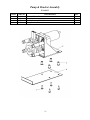
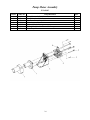
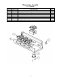
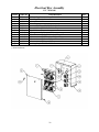
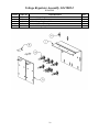
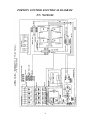
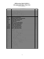
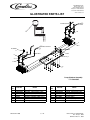
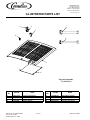
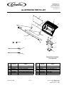
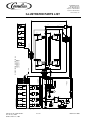
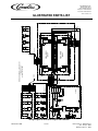
MILLENNIUM (MJ30-4 PB)
(MJ31-4 PB)
(MJ32-4 PB)
(MJ30-4 PC)
(MJ31-4 PC)
(MJ32-4 PC)
INSTALLATION & SERVICE
MANUAL
IMI CORNELIUS INC.
One Cornelius Place, Anoka, Minnesota 55303
Phone (800) 238-3600 or (612) 421-6120 Fax (612) 422-3255
Part No. 85318
Rev. B 2/99
Table of Contents
Description ...............................................................................................................................Page 2
Specifications ...........................................................................................................................Page 3
Receiving & Unpacking ...........................................................................................................Page 4
Installation ................................................................................................................................Page 4-6
• Connect Drain
• Connect Water Supply
• Fill Ice Water Bath
• Connect Power Supply/Start Refrigeration
• Purge Air from System
• Connect B-I-B Concentrate
• Priming the Concentrate Pumps
• Sanitizing prior to Initial Use
• Apply Sealant to Base & Counter Top
Programming Instructions ........................................................................................................Page 6
Brixing Concentrate .................................................................................................................Page 6
Cleaning & Sanitizing the System............................................................................................Page 7-8
• Flushing the Concentrate Lines & Valves
• Cleaning & Sanitizing the Concentrate Lines & Valves
Daily Cleaning & Maintenance ................................................................................................Page 8
Maintenance of the Refrigeration System ................................................................................Page 8-9
• Cleaning of the Refrigeration Components
• Ice Water Bath Cleaning
Troubleshooting Guide.............................................................................................................Page 10-17
Wiring Diagram........................................................................................................................Page 18
Exploded View/Parts Identification .........................................................................................Page 19-29
Recommended Spare Parts (Service Agents Only) ..................................................................Page 32
Optional Accessories................................................................................................................Page 33
Warranty...................................................................................................................................Page 34
1
General Description
The Millennium™ is a state of the art four product B-I-B juice
dispenser. It’s integral high performance, dual speed peristaltic mini
pumps eliminate the need to purchase separate B-I-B pumps. The
Millennium™ can draw product directly from the B-I-B’s up to 50
feet away (15 feet vertically) allowing for greater installation
flexibility! Additionally, the Millennium™ incorporates a unique
valve assembly which mixes the concentrates more thoroughly than
similar models.
Wilshire realizes that counter space is at a premium in any
operation. The Millennium™ maximizes the use of counter space by
providing four product capability in a 15 inch wide chassis. Because
the air circulation is through the top, the Millennium™ can be
installed with zero clearance in the back. For improved
serviceability, all components can be accessed through the top or
front without disturbing equipment placed on either side.
With it’s innovative compact design, reduced operating expense, ease of use and service we’re certain the
Millennium will meet the most demanding conditions for many years to come.
2
30 in. (76.2 cm)
Specifications
9-1/2 in.
(24.13 cm)
28.25 in. (71.75 cm)
15 in. (38.1 cm)
Model Number .........................................................................................................................MJ30-4
Electrical Ratings .......................................................................... 115VAC / 1 Phase / 60 Hz, 10 Amps
Electrical Connection .................................................................... 3 Prong Plug w/ Ground (supplied)
....................................................................................................... 2 Prong Plug w/ Ground (supplied with
....................................................................................................... export modles)
Power Supply ................................................................................ 15 Amp @ 120 volts
....................................................................................................... 10 Amp @ 220 volts
Water Requirements ...................................................................... 3/8 in. (9.5 mm.) SAE male flare inlet
....................................................................................................... 20-100psi (1.4-7bar) max. static
pressure
....................................................................................................... 3.0 oz. (88.7 ml.) water flow per second
Refrigeration.................................................................................. 8.5 oz. R-134a Refrigerant
....................................................................................................... 1/3 hp. Compressor
....................................................................................................... Test Pressures:
....................................................................................................... High 460 psi (31.2 bar)
....................................................................................................... Low 200 psi (13.5 bar)
....................................................................................................... Air Cooled Condenser
Recommended Clearance .............................................................. 18 in. (45.72 cm.) on top, 4 in. on sides
Weight ........................................................................................... Shipping, 150 lbs (68.1 kg.)
....................................................................................................... Operation, 241 lbs (109.4 kg.)
Approvals ...................................................................................... U.L., C.U.L., N.S.F.
* Low speed rating is 2/3 of the high speed
3
4. Remove the four 9/16” (15 mm) retaining
bolts from the underside of the shipping
pallet by carefully tilting the dispenser from
side to side.
Receiving & Unpacking
1. Inspect the carton and note any damage,
regardless if it appears minor. If the carton is
damaged, note on the consignee copy of the
freight invoice “exterior carton damage concealed damage possible.”
5. With the assistance of another person, lift
the dispenser from under the base and place
it on the counter.
The dispenser is extremely heavy when
operational. Make certain the counter can
support a minimum of 300 lbs directly
below the dispenser.
2. Cut the plastic banding strap and remove the
exterior carton sleeve, internal fillers and
plastic bag around the dispenser. Carefully
inspect for damage.
Installation
Note: IMI Cornelius is not responsible for
damaged freight. If damage is found, you
must save all packaging material and
contact the freight carrier. Failure to
contact the carrier within 48 hours of
receipt may void your claim.
Typically the dispenser is placed directly on the
counter and a food grade silicone sealant applied
around the base. However, an optional leg kit is
available. The following instructions assume the
optional leg kit will not be used.
3. Confirm receipt of the installation kit
#720202300 packaged with the dispenser. If
any item is missing, contact our customer
service department at 1-800-238-3600
Monday - Friday between the hours of
8:00 AM and 4:30 PM CST.
Depending on the type of counter, it may be
necessary to provide access through
the counter at the rear of the dispenser
for the drain, power, water and
concentrate connections. Refer to the
template enclosed in the installation kit.
Kit Contents:
Connect Water Supply:
Qty
4
4
5
6
10
10 ft.
4 ft.
1
4
2
1
Description
3/8” barb
3/8” swivel nut
3/8”x3/8” elbow barb
3/8” nylon washer
#170 clamps
3/8” braided tubing
1/2” I.D. clear tubing
1/2”x1/2” 90o elbow
Generic B-I-B connectors
Flavor strip kits
Installation template
Water pipe connections and fixtures directly
connected to a potable water supply shall be
sized, installed, and maintained according to
federal, state, and local laws.
Wilshire recommends that a ½” O.D. copper
supply line with a shut-off valve and water filter
be located within 3-6 feet (0.91-1.83 m) of the
dispenser.
a. Assemble the 3/8” braided water supply line
furnished in the Installation Kit by attaching
the straight barb on one end and the elbow
barb on the other. Secure with clamps
provided.
4
b. Insert a 3/8” nylon washer into the elbow
Connect B-I-B Concentrate
barb of the supply line. Connect the
assembled
supply line
to the water
inlet fitting
located on
the rear of
the dispenser.
a. Attach the supplied 3/8” (9.5mm) elbow
barbs to the end of each 3/8” I.D. B-I-B
concentrate supply line (not supplied).
Secure with clamps provided. Insert a 3/8”
nylon washer into the elbow barb and
connect the supply lines to the rear of the
dispenser noting the valve numbering
(numbered 1-4 from left to right as viewed
from the front of the dispenser).
c. Connect the water supply line to the shut
off. Turn on the water and check for leaks.
b. Route the concentrate supply lines to the
NOTE: The dynamic water pressure must be 20
PSIG (1.4 bar) minimum to ensure correct valve
flow control and must not exceed 100 PSIG
(7 bar) to avoid valve damage.
B-I-B location and attach the gray plastic
B-I-B connector (supplied) to the end of
each line. Secure with clamps provided.
Connect Drain:
Fill Ice Water Bath:
a. Attach the clear drain hose to the barb fitting
a. Remove the top cover
on the drip tray. Route the drain hose out
from the rear of the dispenser and connect it
to a suitable drain source, ensuring
compliance with all federal, state, and local
plumbing codes. Slide the drip tray into
place.
b. Remove the large red plastic plug from the
filler hole in the top of the refrigeration
deck.
c. Fill the water bath with cool water until it
begins to trickle out of the overflow tube.
Purge Air from the Water Coil
d. Reinstall the red plastic plug and top cover.
Prior to initial use, purge all air from the valves
by pushing the dispensing switch repeatedly.
Continue until a steady flow of water is
observed. Repeat the above on the remaining
valves.
Connect Power Supply / Start
Refrigeration:
a. Start the refrigeration system by plugging
Priming the Concentrate Pumps
the power cord into a 115 VAC (+ 10%),
15 amp grounded receptacle.
a. Turn off the water supply.
The Millennium forms an ice bank of
approximately 30 lbs (13.61 kg) in 4-5 hours at a
room temperature of 75oF (24oC). Once the ice
bank has grown to the proper size, the ice bank
control will shut down the refrigeration circuit.
b. Connect the concentrate lines to their
respective B-I-B.
c. Depress and hold each start button until
concentrate is observed flowing from the
dispense nozzle.
NOTE: It is normal to see water trickle from
the over flow as the ice bank forms.
d. Turn on the water supply.
5
NOTE: The portion control has a full memory
retention in case of a power failure.
Sanitizing Prior to Initial Use
The beverage system must be cleaned and
sanitized after installation is completed to safe
guard against any possible contaminants which
may have entered the system during transport or
installation. Refer to the “Cleaning & Sanitizing
the System” section of this manual for
procedures.
SMALL
MEDIUM
LARGE
S
M
L
EXTRA-LARGE
XL
▲▼
Apply Sealant to Base & Countertop
L.E.D.
CANCEL/POUR
CANCEL/POUR ▲▼:
If the optional legs are not used to raise the
dispenser off the counter, the entire perimeter of
the base must be sealed at the counter top with
silicone (or other food grade approved sealant)
in order to comply with N.S.F. standards. Refer
to the template supplied in the Installation Kit.
a. Push and release cancel/pour button to stop
the valve from dispensing.
b. Push and hold for a continuous pour.
Brixing Concentrate
Programming Portion
Control (optional)
The following procedures describe how to adjust
the water to concentrate ratio (brix) according to
taste. Contact your concentrate supplier for
recommended brix ratios.
a. Simultaneously, press and hold “S” (small)
and “XL” (extra large) push button switches
on the Coded Autoset Portion Control
Module until the LED light in the lower
right hand corner of the module starts
blinking. Release the switches. The blinking
LED indicates the programming mode is
active.
a. Remove the flavor strip cover above the
dispense valves.
b. Sample the finished drink. Increase or
decrease the water ratio by turning the water
flow control screw clockwise (more water)
or counterclockwise (less water) until the
desired water to concentrate ratio is
achieved. Repeat procedure on remaining
valves.
b. Place the cup under the white mixing valve
nozzle and push the selected size button
(small, medium, large, or extra large). Hold
the button in until the cup fills to the desired
portion, then release the button. Repeat the
above procedure for the remaining sizes.
c. Replace the flavor strip cover.
NOTE: If the flow control does not respond
there may be debris caught between the internal
ceramic spool and sleeve. Try dislodging the
debris by pressing the dispense switch several
times or turning the flow control adjustment
screw all the way in and out several times.
c. After programming all the drink sizes, press
and release the “cancel/pour” ▲▼ switch to
return the Coded Autoset Portion Control to
the operational mode. The blinking LED
light will go out.
d. If at a future date, it is decided to change the
portion size of the drinks, the individual
sizes can be adjusted by the above
procedure. It is not necessary to reprogram
every size.
6
Cleaning & Sanitizing the
System
c. Connect the bag valve to the gray bag
The dispenser must be cleaned and sanitized
after installation and as required by state and
local health departments, or every 3 months
minimum. Your state or local health codes may
require more frequent and extensive sanitizing
procedures.
d. Depress and hold the dispense button until
connector and submerse the parts in the
bucket of hot water.
the concentrate has been fully purged from
the product lines and valves.
IMPORTANT
Do Not flush more than three valve circuits
simultaneously.
Cleaning and Sanitizing Equipment
and Supplies:
•
•
•
•
•
•
e. Once the concentrate is purged, pulse each
valve for 15 seconds on and then release the
button. Repeat this pulsing for 15 cycles for
each circuit being cleaned. Once the 15
cycles have been completed, allow each
valve to dispense for 3 continuous minutes.
Recommended sanitizer/cleaner:
Stera-Sheen® Green Label prepared to
ensure 200 ppm of available chlorine
(one-2 oz. packet/1 gallon (3.8 L) of water =
200 ppm). Solution temperature should be
between 80°F - 100°F (26.7°C - 37.8°C).
One clean 5 gallon (19 L) bucket
One clean 1 gallon (3.9 L) container or
bucket
Clean non-abrasive clothes
A small brush
Three empty bag in the box bags (to cut
valve fittings off)
f. Remove the nozzles and static mixers from
the dispenser and rinse them under hot tap
water to remove any remnant of excess
concentrate. Repeat for each circuit to be
cleaned.
g. Replace the nozzles and static mixers into
their proper location.
h. Discard any remaining hot water left in the
bucket.
Flushing the Concentrate Lines &
Valves
Cleaning & Sanitizing the
Concentrate Lines and Valves
Cleaning and sanitizing is not required for
potable water circuits. Potable water lines
should remain connected and operational during
the cleaning and sanitizing procedures for juice
circuits.
a. Prepare 5 gallons (19 L) of Stera-Sheen®
Green Label cleaning and sanitizing solution
by mixing one 2 oz. packet/1 gallon (3.8 L)
of potable water. This will provide enough
sanitizing solution to clean and sanitize all 4
concentrate circuits for most installations.
Installations that have 50 or more feet of
concentrate line may require more sanitizing
solution.
a. Fill the 5 gallon (19 L) bucket with clean
extremely hot tap water, approximately
140oF (60oC).
b. Take the three empty bag in the boxes and
remove the bags from the carton. With
scissors, cut the bag valve off of the bag and
clean the valve by rinsing it under hot tap
water.
IMPORTANT
Use potable water at 80°F-100°F (26.7°C26.7°C) to create solution. Water
temperatures above this range will
breakdown the chlorine count and minimize
sanitation.
7
b. Submerse the bag connector and bag valve
Daily Cleaning and
Maintenance
assembly into the bucket of sanitizing
solution.
c. Depress and hold the dispense button until
a. On a daily basis, clean the external cabinet
sanitizing solution is dispensed through the
mixing valves nozzle.
splash areas using a clean damp cloth.
Remove and wash the cup rest, dispensing
nozzles, and static mixers with clean water.
Wipe dry with a clean soft cloth.
d. Pulse each valve for 15 seconds on and then
release the button. Repeat this pulsing for 15
cycles for each circuit being sanitized. Once
the 15 cycles have been completed, allow
the sanitizing solution to stand in the
product lines and valves for 30 minutes.
b. Wipe the drip tray in place on the unit, wash
the tray out with a mild soap solution, then
rinse the tray by pouring water down the
drip tray’s drain.
e. While waiting, remove the nozzles and static
c. Clean all external surfaces of the dispenser
mixers and place them into a separate
container with 2 qts. (1.9 L) of sanitizing
solution. Agitate vigorously using the small
brush to remove any excess concentrate.
Allow the parts to soak for 30 minutes.
with a sponge and a mild soap solution.
Rinse the sponge out with clean water, then
wring the excess water from the sponge and
wipe all external surfaces of the dispenser.
d. Wipe the dispenser dry with a clean soft
f. Clean the dispensing valves mixing chamber
cloth. DO NOT USE ABRASIVE TYPE
CLEANERS. Install the cup rest,
dispensing nozzles, and static mixers on the
dispenser.
with the brush and sanitizing solution (this is
the cavity from which the nozzle is
removed).
g. Replace the nozzles and static mixers into
Maintenance of the
Refrigeration System
their proper locations and discard the
sanitizing solution used to soak them in.
Note: Do not reuse the sanitizing solution used
to clean the nozzles, static mixers, etc.
Cleaning of the refrigeration components
should be performed by a qualified service
technician.
h. Activate the dispensing valves for two more
cycles (15 seconds on then off) with
sanitizing solution then run solution
continuously through the dispensing valves
for 2 minutes.
a. Continuous maintenance of this dispenser is
a basic requirement for proper operation and
sanitation, including all support equipment
utilized in the daily operation of this
equipment.
i. Disconnect the bag valves from the gray bag
connectors and re-connect the bag
connectors to their appropriate product bags.
b. Cleaning of the Refrigeration Components:
j. Depress and hold each dispense button until
c. Disconnect the power before removing the
juice appears at the outlet of the dispensing
nozzle. Dispense and discard two 8 oz.
(237 ml) cups of juice and verify that there
is no chlorine off taste
d. The dispenser’s ventilation grilles and the
top bonnet of the dispenser.
condenser fins should be cleaned
periodically
to
maintain
efficient
refrigeration and to avoid compressor
failure. The condenser fins can be cleaned
8
with a vacuum cleaner or a soft bristle
brush.
of the ice bank control. Never use an ice pick
or other instrument to remove ice from the
evaporator. Such practice can result in a
punctured refrigerant circuit or damage to the
water bath tank.
e. Clean
the exterior surfaces of the
compressor, agitator motor, fan motor, and
fan blade with a damp cloth to wipe off the
accumulated dust.
d. Once the ice bank is sufficiently melted, lift
the entire refrigeration deck up and away
from the water bath by lifting the deck using
it’s service handle strap.
Ice Water Bath Cleaning
The water bath should be cleaned to obtain
maximum cooling efficiency. It is recommended
that the water bath be cleaned two to four times
annually, depending upon local conditions
and/or as required by state and local health
departments.
e. Prepare 1 gallon (3.9 L) of cleaning and
sanitizing solution (see “Sanitizing the
Concentrate Lines & Valves”). Pour the
cleaning and sanitizing solution into the
water bath and clean the sides and bottom of
the tank, the product coils, and associated
brackets with a fiber brush.
A convenient time to do this is at the time the
dispenser is being sanitized. To save time, the
water bath can be drained while the dispenser is
being sanitized.
f. Utilizing the cleaning and sanitizing solution
in the water bath, the fiber brush, and a
clean cloth soaked with sanitizing solution,
clean the refrigeration deck’s evaporator
coils, agitator motor shaft and blade, and the
ice bank sensing bulb.
a. Remove the cup rest and splash panel to
access the water bath’s drain hose. Extend
the drain hose to a suitable waste receptacle
and allow the water bath to drain.
g. Drain the cleaning and sanitizing solution
from the water bath and rinse/flush all the
components with clean water.
b. Remove the dispenser’s top bonnet by
removing the two screws located on the top
of the bonnet. While lifting the bonnet up
and away from the dispenser, unplug the
merchandiser electrical cord from the power
strip located on the refrigeration deck.
h. Re-install the refrigeration deck into the
water bath and secure with two screws.
i. Connect the refrigeration deck’s power strip
to the dispenser’s power cord. Connect the
red, white and blue 12 pin plugs to the
electrical box. Connect the key switch to the
transformer.
c. In order to remove the refrigeration deck for
the water bath and evaporator cleaning,
remove the two screws that secure the deck
to the cabinet structure. Unplug the
refrigeration deck’s main power strip cord
from the dispenser’s power cord. Disconnect
the red, white and blue 12 pin plugs from the
electrical box. Disconnect the key switch a
by unplugging the white 2 pin plug at the
transformer.
j. Fill the water bath with cool potable water
until water begins to flow from the overflow
tube.
k. Plug the merchandisers power cord into
power strip located on the refrigeration deck
and re-install the top bonnet. Secure the
bonnet assembly with two screws.
Note: It will be necessary to melt the ice bank
to be able to pull the refrigeration deck up and
away from the dispenser. Warm water may be
used to accelerate the melting. In order to
prevent ice bank control damage, do not direct
the warm water stream on to the sensing bulb
l. Install the splash panel and cup rest and plug
the dispenser’s power cord into the electrical
outlet.
9
Troubleshooting Guide
Problem
DISPENSER IS TOTALLY
INOPERATIVE
DISPENSER WILL NOT
COOL
Probable Cause
No power present at the
source.
Check the power circuit for a blown
fuse or tripped circuit breaker. Check
the supply line for the proper
amperage and voltage
ratings.....dedicated 15 amps /115
volts.
Power is present at the
source...dispenser is still
inoperative.
Check the power cord connection
located behind the front splash panel.
Refrigeration shut off switch
is in the off position.
Refrigeration shut off switch is
located on the top of the dispenser .
This switch will disable the
compressor and the condenser fan
motor. Be sure the switch is in the on
position.
Low water bath level.
Check water bath level. If 2 gallons
or more are added, cause of problem
has been confirmed.
Depleted ice bank ( not
applicable after period of
heavy usage.)
Check compressor. If running, allow
the system time to recover
(approximately 1 hour). If
compressor is not running or the
system is not recovering see the
Refrigeration System
Troubleshooting section.
Defective Ice bank control.
See Refrigeration System
Troubleshooting section.
Key lock switch in the OFF
position.
Check position of the key lock
switch. Check for loose wire
connections. Run continuity check,
replace as needed.
Transformer not connected or
defective.
Check the connection between the
power strip and the transformer.
Check transformer output at terminal
junction on control box for 26 VAC.
Fuse blown between the
transformer and voltage
regulator boards.
Check the fuse located in the
electrical box, left side. This box is
located on the refrigeration deck and
will require the removal of the upper
bonnet. Replace fuse as needed.
Drink temperature should be
35-45°F (2-7°C)
WITH POWER PRESENT,
UNIT WILL NOT DISPENSE
ALL VALVES.
Remedy
10
Troubleshooting Guide
Problem
UNIT DISPENSING
CONCENTRATE ONLY NO
WATER TO ALL VALVES
FROM SINGLE VALVE
UNIT WILL NOT DISPENSE
WATER OR
CONCENTRATE.
Probable Cause
Remedy
No water reaching dispenser
from the water supply line.
Check line to see if the water is shut
off at the source.
Water pressure over 100 psi or
7 bar. High pressure will not
allow the water solenoids to
open.
Install regulator onto incoming water
line to reduce the pressure to between
30 and 80 psi. (2-5- bar).
Freeze up of water coil.
Refer to the Refrigeration System
Troubleshooting section.
Inoperative or defective push
button switch, or portion
control board.
Check for loose or broken wire
connections at the switch. Check the
continuity of switch. Replace as
needed.
Defective Voltage Regulator
(VRB) board.
The VRB boards are contained in the
electrical box mounted on the
refrigeration deck.. There is one for
each valve.
CAUTION: Access to this panel
requires the removal of the upper
bonnet while the dispenser is
energized and operational.
Check the power input for 26 VAC
and the output for 28 VDC.
FROM SINGLE VALVE,
UNIT IS DISPENSING
CONCENTRATE ONLY.
Inoperative water valve
solenoid coil.
Check to see all wire connections are
secured at the coil. Check power for
26 VDC. If power is present, coil
maybe defective , replace as needed.
Armature maybe stuck, disassemble
and check function. Return spring
could also be defective replace as
needed.
Solenoid makes clicking
sound when energized, but
still does, not function.
Disassemble the coil assembly and
check plunger seal for defects.
Replace as required. Inspect valve
seat for restrictions.
Flow control binding or
defective.
Disassemble flow control assembly
and check the spool and sleeve
assembly . Be sure the spool moves
freely within the sleeve and there are
no restrictions.
11
Troubleshooting Guide
Problem
FROM SINGLE VALVE,
UNIT IS DISPENSING
WATER ONLY.
DISPENSER IS BRIXING
OUT TOO HIGH.
Probable Cause
Remedy
Concentrate container empty.
Replace.
BIB connector is not engaged
or improperly installed.
Check BIB connector for proper
installation. Plunger should be
completely inserted with concentrate
filling the line to the dispenser.
Air leak in product suction
line.
Check the 3/8 flare connection where
the product line attaches to the unit.
Tighten fitting using a flare gasket. If
line is drawing air, pump will not
prime.
No power at the pump motor.
Check for broken or loose wire
connection going to pump motor.
Check for 26 VDC at pump motor
when the dispense button is
energized.
Defective gear motor
assembly.
Check motor function by energizing
circuit with the dispense button. If
motor runs, but pump does not turn, a
broken gear box is indicated. The
pump motor and gear box are
replaced as a unit.
Pump running backwards.
Check the direction of pump
rotation...correct rotation is clockwise
as viewed from the front of the unit.
If pump is turning in a counter
clockwise direction, this indicates the
pump wires are reversed.
Defective concentrate pump
tubing.
Check the pump tubing for ruptures,
wear, etc. Replace as needed
following the instructions printed in
this manual.
Supply water pressure too low. Water pressure must be 20 psi
flowing or above.
Defective flow control.
12
Disassemble and check flow control
assembly for binding, defective
compensating spring , trapped debris.
Be sure the spool moves freely within
the sleeve, replace parts as needed.
Troubleshooting Guide
Problem
Probable Cause
Remedy
DISPENSER IS BRIXING
OUT TOO HIGH. (Cont.)
Low viscosity or highly
concentrated concentrate.
Example 11 to 1 ratio.
Locate the pump switches grouped
behind the front splash panel. They
are marked SPEED SWITCH with
the corresponding valve number.
Placing the switch in the low position
slows down the concentrate pumping
rate requiring less water to brix.
DISPENSER IS BRIXING
OUT TOO LOW.
Supply water pressure is too
high.
Water pressure has a high limit of
100 psi/ 7 bar or over. Place regulator
in supply line to bring pressure down
to 4 bar/ 50 psi flowing.
Defective or improperly
regulating flow control .
High water pressure will cause the
flow control not to regulate properly.
If the problem exists after the
pressure has been reduced to 50 psig/
4 bar, the flow control maybe
defective.. Disassemble and check the
spool and sleeve function and the
compensating spring . Replace parts
as required.
Speed switch in the low
position.
Pump speed switch is in the low
position. Move switch to high
increasing the pumping rate of the
concentrate.
Air leak in the concentrate
suction line.
Check that the concentrate line
connection is secured tightly to the
dispenser with the proper gaskets.
Check the connector at the
concentrate source to be sure it is
properly attached.
Worn concentrate pump
tubing.
Remove the front half of the
concentrate pump and inspect the
tubing . Worn or stretched tubing will
decrease the amount of concentrate
pumped. After 1 year tubing should
be replaced.
Defective poppet valve and or
spring.
Disassemble the right side of the
valve which contains the syrup
poppet assembly. Be sure the valve is
not binding, free of debris, return
spring is actuating and the diaphragm
is not torn or punctured.
13
Troubleshooting Guide
Problem
Probable Cause
Remedy
WATER LEAKS FROM
BOTTOM OF DISPENSING
VALVE.
Nozzle pieces improperly
assembled.
Static mixer inserted in nozzle body
upside down. Cone shaped end must
be visible when remounting the
nozzle assembly to the dispenser.
WATER CONTINUOUSLY
DRIPS FROM NOZZLE.
Water solenoid valve not
shutting off tightly.
Disassemble water solenoid located
at the valve and check for foreign
material in the valve seat. Check the
armature for binding, check the
plunger and the seat for defects.
Replace parts as needed.
UNIT CONTINUES TO
DISPENSE AFTER BUTTON
HAS BEEN RELEASED.
Inoperative or defective push
button switch, or portion
control board.
Check the operation of the push
button for sticking. Check continuity
of switch. Replace as needed.
Relay on voltage regulator
board hangs up or is stuck
open.
Defective Voltage Regulator
(VRB) Board.
TWO OR MORE PUMPS
OPERATE WHEN ONLY
ONE BUTTON IS PUSHED.
Insulator pad missing or not
properly positioned between
the transistor on VRB board
and mounting bracket.
14
CAUTION: Access to this panel
requires removal of the bonnet while
the dispenser is plugged in and
operational. *Voltage regulator board
is found in the electrical box mounted
to the refrigeration deck. There is one
board for each valve. Gently tap the
relay. If dispensing stops, relay was
hung up . If tapping the relay solves
the problem, it should be noted that if
a relay sticks once , it will probably
stick again. Replace as needed.
Pull the connector marked DOOR ,
lower right hand connector on the
VRB board. If the unit still continues
to dispense the VRB board is
defective and needs to be replaced.
On the valve that is dispensing in
error, check the insulator pad
between the transistor on the top of
the VRB board and the mounting
bracket. If this pad is missing or
improperly aligned, the VRB board
will make contact with the bracket.
Current will run through the bracket
and set off the valve. Refer to
drawing found in this manual.
Troubleshooting Guide
Problem
Probable Cause
Remedy
TWO OR MORE PUMPS
OPERATE WHEN ONLY
ONE BUTTON IS PUSHED.
(Cont.)
VRB Board mounting screw
insulator is missing or
improperly installed.
Check the corresponding VRB board
to the valve that is dispensing in
error. Where the screw mounts the
transistor to the bracket, be sure that
the spacer bushing is present and the
screw is not over tightened. Screw
contact with the bracket will cause a
short and the firing of the valve when
other valves are energized.
WITH POWER PRESENT
DISPENSER WILL NOT
COOL
Refrigeration shut off switch
is in the off position.
Refrigeration shut off switch is
located on the top of the dispenser.
This switch will disable the
compressor and condenser fan motor.
Be sure the switch is in the on
position.
Drink temperature should be
35-45°F
2-7°C
Depleted ice bank (not
applicable after period of
heavy usage.)
Remove rear bonnet covering the
refrigeration deck. CAUTION should
be observed when working in this
area as the dispenser is energized and
operational. Check to see if the
compressor is running . If so allow
the system to recover (approximately
1 hour).
WITH POWER PRESENT
COMPRESSOR WILL NOT
RUN.
(Compressor shell is cold to
touch.)
Loose or broken wire
connections.
Check the wire connections at the
compressor. Be sure they are tightly
secured.
Defective compressor start
component.
Check the compressor start relay.
Replace as required.
Ice bank control not connected
or defective.
Check the ice bank control
connections. To test, place jumper
between the 2 leads. If the
compressor starts ,the ice bank
control is defective.
Low refrigerant charge.
Contact a refrigeration service
technician. They will check for leaks
(sign of oil at joints and fitting) and
will recharge if necessary.
Refrigerant restriction.
Refrigeration technician will examine
the system for, kinks in lines,
restrictions, etc. Heat exchanger may
need to be replaced.
COMPRESSOR RUNS BUT
NO COOLING IS TAKING
PLACE.
15
Troubleshooting Guide
Problem
COMPRESSOR RUNS BUT
NO COOLING. TRIPPING
OVERLOAD.
(Compressor shell is hot to
touch).
UNIT IS DISPENSING
CONCENTRATE ONLY
REFRIGERATION SYSTEM
HAS BEEN RUNNING FOR
EXTENDED PERIOD
WITHOUT SHUTTING OFF
FROZEN WATER COIL.
Probable Cause
Remedy
Condenser fan not running.
Check that the condenser fan is
running. If the fan is binding or
turning slowly, an overload condition
will occur.
Inadequate air flow through
the dispenser.
Air flow is top front in, exhaust out
the rear. NEVER PLACE
ANYTHING ON TOP OF THE
DISPENSER. This will block the
airflow over heating the compressor
and causing it to trip the overload.
Blocked condenser fins.
Remove the rear bonnet and check
the condenser fins. If unit is run in a
dusty environment, condenser fins
can become clogged, stopping the air
flow.
Brush out and clean with vacuum.
Ambient air over 100°F 38°C.
If the dispenser is working in an
environment over 100° ambient or is
drawing in discharged air, during a
heavy period, the unit may trip the
overload.
Defective overload.
Overload works on shell temperature
and amperage draw and can be
defective. Replace as needed.
Defective compressor.
Refrigeration technician will verify if
the compressor is defective and needs
to be replaced.
Insufficient water level in the
water bath.
See the Start-up and Operation
Section of this manual. Be sure the
water bath is filled to fill line.
Agitator motor not operating.
Check the agitator motor located on
the refrigeration deck. Be sure it is
plugged in and receiving power.
Check that the impeller is not
obstructed. Replace if needed.
Improperly located ice bank
control sensor.
Melt the ice bank and check the
location of the sensing bulb. Be sure
it is all the way down to the bottom
of the tube.
16
Troubleshooting Guide
Problem
UNIT IS DISPENSING
CONCENTRATE ONLY
REFRIGERATION SYSTEM
HAS BEEN RUNNING FOR
EXTENDED PERIOD
WITHOUT SHUTTING OFF
FROZEN WATER COIL.
Probable Cause
Compressor not cycling off.
17
Remedy
Check the ice bank control. Be sure
that the control has not overheated
and fused the contacts together.
Replace as required.
Millennium 4 Valve Schematic
18
Final Assembly
ITEM PART NO.
DESCRIPTION
QTY
1
50222
Merchandiser
1
2
720203000
Lens “Refreshing Drinks”
1
3
60064003
Fluorescent Bulb, F15T80 (All Voltages)
1
‡
350001
Ballast 115v/60hz
1
‡
60419006
Ballast 230v/50hz
1
‡
60420001
Starter 115v/60hz
1
‡
60419004
Ballast 220v/6hz
1
‡
350164
Socket, Starter
1
4
350061
Lamp Holder
2
5
231050
Reflector
1
6
231051
Wrapper, Stainless Steel
1
7
261142
Bonnet Assembly w/Screen
1
8
400325
Screw
2
9
720200500
Valve Adjustment Cover
1
10
720200400
Valve Enclosure
1
11
84353001
Push Button Switch Assembly
1
12
550088
Condenser
1
13
230509
Shroud
1
14
710160063
Handle
1
15
186074001
Ice Bank Control – All Voltages
1
16
350017
Condenser Fan Motor Blade
1
‡
350095
Condenser Fan Motor 115v/60hz
1
‡
350096
Condenser Fan Motor 220v, 230v/50hz, 60hz
1
17
40-0323
Screw
2
18
230040
Bracket, Agitator Motor
2
19
230303
Heat Sink, Agitator Motor
2
20
350078
Agitator Motor w/out Blade 115/60
1
‡
350079
Agitator Motor w/out Blade, 220v, 230v/50hz, 60hz
1
21
350012
Blade, Agitator
1
‡
36118
Spring Pin
1
23
400262
Plug Cap (Water Fill Hole)
1
24
260970*
Compressor 1/3 Hp R-134a 115v/60hz
1
‡
550001
Accumulator/Dryer
1
‡
350148
Compressor Start Relay 1/3 Hp 115v/60hz
1
‡
350108
Compressor Overload 1/3Hp 115v/60hz
1
‡
260968*
Compressor 1/3 Hp R-134a 230v/50hz
1
‡
350106
Compressor Overload 1/3 Hp 230v/50hz
1
‡
350151
Compressor Start Relay 1/3 Hp 230v/50hz
1
‡
260972*
Compressor 1/3 Hp R-134a 220v/60hz
1
‡
350146
Compressor Overload 1/3 Hp 220v/60 Hz
1
‡
350152
Compressor Relay 1/3 Hp 220v/60hz
1
*-Compressor includes Relay, Overload, Grommets and Sleeves. Start Capacitor is required for 220V
Compressors only and is supplied with the Compressor.
‡ -Indicates item not shown.
19
Final Assembly
ITEM
‡
25
26
27
28
‡
29
‡
30
31
32
‡
‡
33
34
‡
35
36
37
‡
38
39
40
41
42
43
‡
44
45
46
47
48
50
51
52
53
54
‡
‡
‡
‡
PART NO.
350115
400407
350055
350158
350182
720202200
720202201
720201400
720201403
710160156
710160159
710160157
350130
260061
230983
261135
350174
350131
350112
400501
650094
720200700
720200300
720200200
27615
19578
720200600
720200100
89043
231049
261136
261137
230208
400193
48033002
400135
261139
400113
400263
650089
DESCRIPTION
Compressor Start Capacitor 220v/60hz
Hitch Pin
Washer
Grommet
Sleeve
Power Switch, Refrigeration Deck
Transformer Assembly 115v/60hz
Transformer Assembly 220v, 230v/50hz, 60 Hz
Electrical Box Assembly (All Voltages)
Cover, Electrical Box
Refr. Deck Assembly 115v/60hz (w/out Ele. Box & Transformer)
Refr. Deck Assembly 230v/50hz (w/out Ele. Box & Transformer)
Refr. Deck Assembly 220v/60hz (w/out Ele. Box & Transformer)
Power Strip
Bulb Holder
Bracket, Bulb Holder
Cabinet Assembly (Includes Items 47 & 48)
Clip
Main Power Cord
Main Power Cord
Elbow 25 MPTX.5B Nylon
Vinyl Tubing 1/2” ID Overflow
Splash Panel
Dispensing Assembly
Enclosure Assembly (with Speed Switch Mtg Plate)
Key Switch with Keys
Key, Double Sided #2009
Cup Rest
Drain Pan
Vinyl Tubing
Front Panel, Base Riser
Base Riser Assembly
Water Coil Assembly
Bracket
Flare Nut
Nylon Washer
Coupler
Water Manifold Assembly 4 Valve
Fitting El-Barb 3/8 x 1/4 MPT
Dead Head Plug
Drain Hose
QTY
1
4
4
4
4
1
1
1
1
1
1
1
1
1
1
1
1
2
1
1
1
1
1
1
1
2
1
1
6 Ft
1
1
1
1
1
1
1
1
1
1
3 Ft
*-Compressor includes Relay, Overload, Grommets and Sleeves. Start Capacitor is required for 220V
Compressors only and is supplied with the Compressor.
‡ -Indicates item not shown
20
Final Assembly
.
21
Platform Assembly
P/N 720200800
ITEM
1
2
3
4
5
6
7
8
9
10
11
12
13
14
15
PART NO.
720200804
720200801
720200802
48432
720201600
48195006
48309
48310
89078
48114004
48114003
0734801
0704001
0733903
55145
DESCRIPTION
Tube Fittings/Bracket Assembly
Base, Pump
Bracket, Pump Support
Pump & Bracket Assembly Millennium
Harness Assembly, Pumps to Plug
Clamp-Hose, .470”-.XXX” I.D.
Tube Assembly, Pump Inlet
Tube Assembly, Valve Inlet
Tubing-Beverage, 3/8 I.D. Redline
Clamp-Ear, 105 (.413/.346)
Clamp-Ear, 145 (.571/.472)
Rivet, Pop
Screw, #8-32 Type “F” BD HD, 3/8” LG
Bushing-Snap
TY-Wrap 5 1/2” Long
22
QTY
1
1
1
4
1
8
4
4
2.3’
4
2
4
10
2
2
Pump & Bracket Assembly
P/N 48432
ITEM
1
2
3
4
PART NO.
0704105
45185
45283
48420
DESCRIPTION
Screw, 8-32 x 1/2”
Pump & Motor Assembly
Rubber Bushing With Nut Insert
Pump Bracket
23
QTY
4
1
4
1
Pump Motor Assembly
P/N 48405
ITEM
1
2
3
4
5
6
7
PART NO.
45016001
45078
45050
45017001
0702905
45098
45074
DESCRIPTION
Pump Motor with Boot (Item #7)
Pump Complete, 3-Roller
Block Assembly, Pump & Motor
Thumbscrew
Screw, 8-32 x 3/4”
Tubing Kit (1 Pre-Cut Tube and 2 Clamps)
Boot-Pump Motor
24
QTY
1
1
1
4
1
4
1
Dispensing Assembly
P/N 720200300
ITEM PART NO.
DESCRIPTION
1
0704107
Screw, *8-32 THMS, 5/8” LG
2
45027001
Bushing-Nozzle, SL Juice Dispense
3
07033901
Bushing-Snap
4
48415
Valve Block/Bracket Assembly
5
720200301
Support, Valve Block
‡
45123
Static Mixer
‡
31525-057
O-Ring Mixing Nozzle 13/16 O.D. x .676 I.D.
‡
48808-001
Mixing Nozzle with O-Ring
‡ -Indicates item not shown
25
QTY
8
4
2
4
1
4
4
4
Valve Block Assembly
P/N 45045
ITEM
1
2
3
4
5
6
7
8
9
10
11
12
13
14
15
16
17
18
19
20
21
22
23
24
25
26
27
28
29
30
31
32
PART NO.
45177
DESCRIPTION
Holder, Poppet Seal
0720406
15321
15323
18070001
18367
19695001
31525021
18071
48258005
45192
45193
45029
47011
45180
45189
Nut, #10-32 KEPS
Ring-Retain, .242 ID
Armature-EL VLV
Gasket-Rubber 1.055 DIA
Spring-Coil, SS
Guide-AS Small ELVL
O-Ring, 1-1/4 OD x 1.114 ID
Seat-Armature Water, FFV
Spring-Syrup, FFV
Valve Body, Mixing
Valve Block-Water, SL Juice
Plate-Coil Retainer
Diaphragm W/Hole-Valve, MDJ
Spring Actuator-SLJ1000
Armature Tip
1
1
1
1
1
1
1
1
1
1
1
1
1
1
1
47048
45195
45186
31525060
48520001
48978
60280002
07032001
60281001
16779003
27408
49612
31525020
22081
Support-Diaphragm, MDJ
Valve Block, Front Plate
Spring - .360 OD x .032 Wire
O-ring, .539” x .459” x .875” OD
Coil Assembly, -24 V DC
Flow Control/Bonnet Assembly, -FFV
Piston-Water, Ceramic, FFV
Screw, #8-18 x 7/16 Type “25” HHWF SS
Sleeve-Syrup, Ceramic, FFV
Frame – “C” Solenoid
Petro-Gel
Valve Port – Water
O-Ring, 5/16” OD x .176” ID
Washer-Holddown EVLV
1
1
1
1
1
1
1
13
1
1
1
1
1
2
26
QTY
1
Valve Block Assembly
P/N 45045
27
Electrical Box Assembly
P/N 720201400
ITEM
1
2
3
4
5
6
7
8
9
10
11
‡
‡
PART NO.
45238
720201401
720201403
0734801
0704001
59328001
45059
720201701
720201702
720201703
720201704
720202000
0733909
DESCRIPTION
Voltage Regulator Assembly, SLJ1000-2
Enclosure, Electrical
Cover, Electrical Box
Rivet, Pop
Screw, #8-32 Type “F” BD HD, 3/8” LG
Fuse – 6.25 Amp, 250 V, SL Juice Dispenser
Fuse Holder
Wiring, Assembly Pumps to E-Box
Harness Assembly, Speed Switches E-Box 4 FL
Harness Assembly PB Switches E-Box 4 Flavor
Harness Assembly Power E-Box 4 Flavor Millennium
Harness Assembly Pump to E-Box
Bushing Snap 1/4” I.D. x 3/8” O.D.
‡ Items not shown
28
QTY
2
1
1
1
7
1
1
1
1
1
1
1
1
Voltage Regulator Assembly, SLJ1000-2
P/N 45238
ITEM
1
2
3
4
5
PART NO.
45162
45056
45012002
45613
45004001
DESCRIPTION
Bracket-Voltage Regulator, SLJ1000-1
Support-PC Board, SL Juice
Board-Voltage Regulator, SLJ
Fastener, Plastic-VRB Mtg
Insulator-Voltage Regulator
29
QTY
1
8
2
2
2
PORTION CONTROL ASSEMBLY
30
PORTION CONTROL ELECTRICAL DIAGRAM
P/N 720201800
31
Millennium Model MJ30-4
Recommended Spare Parts List
(For 10 Dispensers)
PART NO.
45003100
45123
31525037
45189
45177
47011
45180
45186
45179
18070001
15323
18071
18367
15321
31525020
31525021
48520001
60280002
60281001
31525060
48258005
48978
84353001
45012102
48448
45432
59328001
45016001
45098
186074001
350095
350078
350148
350108
60064003
350001
350164
720200100
720200600
DESCRIPTION
Nozzle & O-Ring Assembly
Static Mixer (inside disp. nozzle)
O-Ring, Dispensing Nozzle
Poppet, Rubber, Valve Mixing Block
Poppet Seal Holder
Diaphragm with Hole, Valve Mixing Block
Spring Actuator, Valve Mixing Block
Spring, Valve Mixing Block
Diaphragm, Support, Valve Mixing Block
Gasket, Rubber, Water Solenoid
Armature Water Solenoid
Armature Seat
Spring, Coil, S/S, Water Solenoid
Ring, Retaining, Water Solenoid
O-Ring, Water Solenoid Valve
O-Ring, Valve Mixing Block
Coil, Water Solenoid, 24 VDC
Piston, Ceramic, Brix Control
Sleeve, Ceramic, Brix Control
O-Ring, Ceramic Sleeve
Spring, Brix Control
Flower Control, Bonnet Assembly
Push Button, Dispense
Circuit Board, Voltage Regulator
Transformer Assembly 115V/60Hz
Switch, Rocker, Speed Adjustment
Fuse, 6.25 Amp, 220 VAC
Pump Gear Motor
Pump Tubing Kit (pre-cut tube with clamps)
Ice Bank Control
Motor, Condenser, 115V/60Hz
Agitator Motor Assembly, 115V/60Hz (w/blade)
Relay, Compressor, 115V/60Hz
Overload, Compressor, 115V/60Hz
Bulb, Fluorescent
Ballast 115v/60Hz
Starter 115V/60Hz
Drain Pan Assembly
Cup Rest
32
QTY
4
4
4
4
4
4
4
4
4
4
4
4
4
4
4
4
2
3
3
3
3
3
4
2
1
2
2
1
3
1
1
1
1
1
1
1
1
1
1
Millennium Model MJ30-4
Optional Accessories
The following options are available for the Millennium Dispenser. For more information, please contact
our customer service department at 1-800-238-3600 Monday-Friday between the hours of 8:00 a.m. and
4:30 p.m. CST.
Part No.
721900000
721900001
721900002
48350007
48350008
721910000
Description
Optional Leg Kit Standard (set of 4 steel legs and 2 support braces
NSU Kit (secures unit for use on ships)
Kit Leg Adjustable
Single, 2 Button Bar Gun Kit
Dual 2 Button Bar Gun Kit
Portion Control Conversion Kit
33
IMI CORNELIUS INC.
Certificate of Warranty
ONE YEAR LIMITED PARTS EQUIPMENT WARRANTY
IMI Cornelius Inc. warrants to the original commercial purchaser/user, that any commercial product of its manufacture bearing
the name “Wilshire” will be free from defect in material and/or factory workmanship, and that if properly installed, maintained,
and serviced in accordance with the Service Manual furnished with the product, it will perform adequately under normal use.
This product warranty shall be effective for a period of one year from the date of original installation or 15 months from the date
of original shipment by IMI Cornelius, whichever period elapses first.
IMI Cornelius Inc.’s obligation, upon return of the part or parts to its factory, transportation charges prepaid, is limited strictly to
replacing or to repairing without charge any part or parts IMI Cornelius finds to be defective in material and/or factory
workmanship during the warranty period. The serial and model numbers and date of original installation of the product must be
given. No part or assembly which has been subject to accident, alteration or misuse or which is not installed, maintained, or
serviced in accordance with the Service Manual furnished with the product, or which is from a machine on which the serial
number has been removed, shall be covered by this warranty. This warranty does not provide for service calls from factory
representatives or from any other agencies and shall not include charges of any nature.
IMI Cornelius Inc. will accept a part, parts, or equipment freight prepaid and return same freight collect to the sender within the
continental U.S. or port of export within the continental limits of the U.S. IMI Cornelius Inc. is not responsible for international
freight, customs fees or duties at country of destination.
ADDITIONAL FOUR YEAR LIMITED WARRANTY ON COMPRESSOR
This warranty shall be effective for a period of four (4) years from the expiration of the above warranty.
The hermetically sealed refrigeration compressor is covered by the above one year limited warranty. In addition to that warranty,
if the compressor fails because of a defect in materials or workmanship during the second through fifth year from the date of
installation, IMI Cornelius Inc. will repair or, at its option, replace the compressor. Labor charges and the cost of relays,
overloads and capacitors are not included.
THIS WARRANTY DOES NOT COVER DAMAGE CAUSED BY LACK OF PREVENTATIVE MAINTENANCE,
IMPROPER INSTALLATION, ACCIDENT, MISUSE, NEGLIGENCE, ALTERATION, FIRE, FLOOD, OR ACTS OF GOD.
In those jurisdictions where liability for damages cannot be disclaimed, original purchasers recovery shall not exceed the cost of
the warranted product.
IMI CORNELIUS INC. ASSUMES NO LIABILITY FOR INCIDENTAL OR CONSEQUENTIAL DAMAGES OF ANY
KIND, INCLUDING, BUT NOT LIMITED TO, SPOILED PRODUCT, LOST PROFITS, OR DAMAGE TO OTHER
PROPERTY.
THIS WARRANTY IS EXCLUSIVE AND IN LIEU OF ALL OTHER WARRANTIES, WHETHER WRITTEN, ORAL, OR
IMPLIED, INCLUDING ANY WARRANTY OF MERCHANTABILITY OR FITNESS FOR A PARTICULAR PURPOSE,
AND SUPERSEDES AND EXCLUDES ANY ORAL WARRANTIES OR REPRESENTATIONS OR WRITTEN
LANGUAGE IN ANY MANUAL, LITERATURE, ADVERTISING BROCHURE OR OTHER MATERIALS NOT
EXPRESSLY DESIGNATED IN WRITING AS A “WARRANTY”.
IMI Cornelius, Inc.
One Cornelius Place
Anoka, Minnesota 55303
612-421-6120 / 800-238-3600
612-422-3255
34
IMI CORNELIUS INC.
One Cornelius Place
Anoka, MN 55303-6234
Telephone 1-800-238-3600
Facsimile 1-800-258-0255
www.cornelius.com
ILLUSTRATED PARTS LIST
MILLENNIUM II 4000
Millennium II 4000
1 of 22
Manual Part No.: 620919547IPL
Rev.: B July 7, 2003
© IMI Cornelius Inc., 2003
IMI CORNELIUS INC.
One Cornelius Place
Anoka, MN 55303-6234
Telephone 1-800-238-3600
Facsimile 1-800-258-0255
www.cornelius.com
ILLUSTRATED PARTS LIST
55
44 88 99
1110 106 6
11
12
12
3 77
3
11
22
CABINETRY
Item
No.
1
2
3
4
5
6
Part No.
620050654
620708527
620517118
620048118
620048121
620048117
Manual Part No.: 620919547IPL
Rev.: B July 7, 2003
© IMI Cornelius Inc., 2003
Item
No.
7
8
9
10
11
12
Name
Splash Panel
Cup Rest
Drip Tray
Right Side Panel
Back Panel
Left Side Panel
2 of 22
Part No.
172265000
620710207
620048120
620710208
620048119
37958
Name
O-Ring (Drip Tray)
Stainless Steel Insert - R
Inner (Bracket) - R
Stainless Steel Insert - L
Inner (Bracket) - L
Leg, 4 inch
Millennium II 4000
IMI CORNELIUS INC.
One Cornelius Place
Anoka, MN 55303-6234
Telephone 1-800-238-3600
Facsimile 1-800-258-0255
www.cornelius.com
ILLUSTRATED PARTS LIST
12 PIN
RED
To Valves
Out Base
to B.I.B.
OUT BASE TO B.1.B.
TO VALVES
BLK
BLK
ORG
ORG
O B O B
R L R L
G K G K
18
13
1
10
11
2
BLK
BLK
ORG
ORG
O B O B
R L R L
G K G K
3
4
5
5
4
4
Out Base to B.I.B.
OUT BASE TO B.1.B.
7
7
To Valves
TO VALVES
3
3
2
12
2
17
8
9
1
1
9
10
12
11
6
6
Pump Platform Assembly
P/N 620048605
Item
No.
1
2
3
4
5
6
7
Part No.
Name
620048604
620049104
200498003
45185
45283
70178
48456
Pump Platform 4V
Bracket, Tubing Back Pump
Nut, Hex 8-32
Pump & Motor Assembly
Bushing, Rubber w/Nut Insert
Screw 8-32
Tubing
Millennium II 4000
3 of 22
Item
No.
8
9
10
11
12
13
Part No.
41232
620709025
620709026
48195-003
48114004
720201600
Name
Fitting, 1/4 Barb
Fitting, Pump Inlet Front
Fitting, Pump Inlet Rear
Clamp, Hose
Clamp #10.5
Harness, Pump
Manual Part No.: 620919547IPL
Rev.: B July 7, 2003
© IMI Cornelius Inc., 2003
IMI CORNELIUS INC.
One Cornelius Place
Anoka, MN 55303-6234
Telephone 1-800-238-3600
Facsimile 1-800-258-0255
www.cornelius.com
ILLUSTRATED PARTS LIST
1
1
2
2
3
3
22
22
26
26
9
9
25
25
8
8
10
10
24
24
11
11
20
21
20
4
21
4
22
22
23
23
5
5
6
6
Lower Housing Assembly
7
7
P/N 620516502
Item
No.
1
2
3
4
5
750100133
750500001
70959
620045743
620045430
Waterbath Assembly
Insulation, Gasket Slit
Nut, 8-32 Hex Nutsert
Pump Base 4V
Support, Pump Base
6
7
8
9
10
11
12
13
71822024
620517902
620047602
200498003
50459
0733903
18689004
18689008
Screw 8-18
Extension, Leg
Channel, Pump Platform
Nut Hex 8-32
Bushing, 7/8”
Bushing, 1-5/16ID X 1/609OD
Label WATER (Not Shown)
Label Label SYR #1 (Not Shown)
Part No.
Item
Part No.
No.
14
18689009
15
18689010
16
18689011
17
18689112
18
313457000
Name
Name
Label Label SYR #2 (Not Shown)
Label Label SYR #3 (Not Shown)
Label Label SYR #4 (Not Shown)
Label DRAIN (Not Shown)
Label, Electric Shock Hazard
(Not Shown)
Manual Part No.: 620919547IPL
Rev.: B July 7, 2003
© IMI Cornelius Inc., 2003
4 of 22
19
20
21
22
23
24
25
26
620919365
50386
1971
40705
50249
50326
31699004
60446
Label, Slack (Not Shown)
Tubing, 1/2 ID
Fitting, L-Barb
Clamp
Tubing, Insulation 1/2 ID
Insulation Tape (Not Shown)
Cap-Plug
Tubing, 1/4 ID
Millennium II 4000
IMI CORNELIUS INC.
One Cornelius Place
Anoka, MN 55303-6234
Telephone 1-800-238-3600
Facsimile 1-800-258-0255
www.cornelius.com
ILLUSTRATED PARTS LIST
25
38
40
38
40
25
REFRIGERANT 134A
27
39
27
39
9
9
35
35
7
7
8
12
12
8
16
16
2
2
18
17
18
17
29
28
29
28
15
15
41
41
10
10
24
24
20
20
43
13
43
18
3
13
18
3
19
19
32
1
32
1
21
21
31
31
LABEL TO IDENTIFY RED LEADS
14
14
30
LABEL TO BE PLACED ON TOP OF E-BOX (
30
PART# 620046045)
26
11
26
11
44
4
4
44
5
5
CONNECT ICE BANK PROBE TO BRACKET
WITH PROBE RETAINING CLIP
42
42
23
23
6
6
22
22
36
33
36
33
37
37
Refrigeration Deck Assembly
P/N 620048607
Millennium II 4000
5 of 22
Manual Part No.: 620919547IPL
Rev.: B July 7, 2003
© IMI Cornelius Inc., 2003
IMI CORNELIUS INC.
One Cornelius Place
Anoka, MN 55303-6234
Telephone 1-800-238-3600
Facsimile 1-800-258-0255
www.cornelius.com
ILLUSTRATED PARTS LIST
Item
No.
1
2
3
4
Part No.
Name
Item
No.
23
24
25
26
Part No.
Name
27
750100402
750100097
52200
620042708
620042709
313456000
Bracket Probe GIBC .875
Filter Dryer Assembly
Refrigeration Deck
Agitator Motor Assembly 115V
Agitator Motor Assembly 230V
Label Hazard Caution Cover
28
60536002
Label Warning Danger Moving
Parts
Washer FT 187 437 STZI
620045999
750300227
750300083
71091
Refrigeration Platform 4V
Screw SM #8 HXWS 12 STZI
Handle Ref Deck
5/16-18 Nylon Insert Locknut
5
620711604
6
750100004
7
29
70051
8
9
10
2129
2519
620607906
20223010
750300240
34877001
Insulation Refrigeration Deck
4V
Refrigeration Evaporator
Assembly 4V
Compressor 1/3 HP 120/60
Compressor 1/3 HP 230/50
Compressor 1/3 HP 230/60
Washer FT 489 922 065 STZI
Lead-Ground Assembly
Screw MA 8-32 HXWS 12 STZI
30
31
32
11
12
1450580001
90751
Label Ground Earthing
Label Notice Rfg Test
33
34
750300243
750900819
620710702
620710709
620313342
750300401
13
14
398034400
70226
Pin Hitch 080D 1.562 STZI
Screw SM 10 TB PAPH 24 STZI
35
36
50335
20322
15
560003701
Condenser Coil & Fan 07W
120/60 .36
Condenser Coil & Fan 230 50/
60
Tube Discharge Comp Oly
Line Suction Compressor Oly
Tube Process Oly 1/3 HP Disp
Accumulator D80+ & 134A
Line Accumulator Inlet Tube L &
M
Probe Ice Bank GCC
Clip Retaining Probe Plastic
Black
37
20354
Tab Grounding Oly
Label 24VAC
Transformer 115V-26V/24V
Transformer 230V-26V/24V
Harness Power Millennium
Guard 1/32” Fishpaper Transformer
Insulation Armaflex 1-3/8 x 3/8
Rod #6 Phoson Brazing 1/16
Dia
Solder 1/16 Dia #35 Silver
38
39
40
41
42
50326
50163-1
50705
750100241
750500002
Insulation Tape
Insulation Tube
Tie Cable
Baffle Air Deck
Wrap Social
43
44
620049120
750100096
Transformer Bracket
Condenser Platform
560003702
16
17
18
19
20
750100024
750100079
750300025
31738003
750300232
21
22
560003860
440000906
Manual Part No.: 620919547IPL
Rev.: B July 7, 2003
© IMI Cornelius Inc., 2003
6 of 22
Millennium II 4000
IMI CORNELIUS INC.
One Cornelius Place
Anoka, MN 55303-6234
Telephone 1-800-238-3600
Facsimile 1-800-258-0255
www.cornelius.com
ILLUSTRATED PARTS LIST
2
5
4
1
3
6
Water Coil Assembly
P/N 750100071
Item
No.
1
2
3
4
Part No.
70320
750100042
750300064
750100065
Millennium II 4000
Item
No.
5
6
7
Name
Rivet
Flow Baffle
Bracket, Flow Baffle
Coil, Lower
7 of 22
Part No.
750100066
750100082
750500101
Name
Coil, Upper
Bracket, Coil
Spacer (Not Shown)
Manual Part No.: 620919547IPL
Rev.: B July 7, 2003
© IMI Cornelius Inc., 2003
IMI CORNELIUS INC.
One Cornelius Place
Anoka, MN 55303-6234
Telephone 1-800-238-3600
Facsimile 1-800-258-0255
www.cornelius.com
ILLUSTRATED PARTS LIST
88
4a
4a
55
33
22
77
1
1
Pump & Motor Assembly
P/N 45185
Item
No.
1
Part No.
Name
45016001
Pump Motor with Boot (item 7)
Item
No.
6
2
3
4a
45078
45050
45017001
Pump Complete, 3-Roller
Block Assembly, Pump & Motor
Thumbscrew
7
8
46
5
0702905
Screw, 8-32 x 3/4”
Manual Part No.: 620919547IPL
Rev.: B July 7, 2003
© IMI Cornelius Inc., 2003
8 of 22
Part No.
45098
45074
45078
720701407
Name
Tubing Kit (1 Pre-cut Tube & 2
Clamps) (Not Shown)
Boot, Pump Motor (Not Shown)
Roller
Machine Screw, Phillips Pan
Head (Not Shown)
Millennium II 4000
IMI CORNELIUS INC.
One Cornelius Place
Anoka, MN 55303-6234
Telephone 1-800-238-3600
Facsimile 1-800-258-0255
www.cornelius.com
ILLUSTRATED PARTS LIST
10
10
11
11
12
12
13
13
22
44
1
33
1
5
5
66
7
7
88
99
Item
No.
1
2
3
4
5
6
7
Part No.
620045438
45508200
07032001
720500033
45027001
0704107
45123
Millennium II 4000
Name
Beverage Valve Support 4V
Valve Block Assembly
Screw 8-18
Mixing Chamber
Nozzle Bushing
Screw 8-32
Static Mixer
9 of 22
Item
No.
8
9
10
11
12
13
Part No.
31525037
48808001
620049103
70171
45586
70152
Valve Panel Assembly
P/N 620407478
Name
O-Ring
Mixing Nozzle
Touch Panel Bracket 6V
Screw 8-32
Washer, Hold Down
Screw 6-32
Manual Part No.: 620919547IPL
Rev.: B July 7, 2003
© IMI Cornelius Inc., 2003
IMI CORNELIUS INC.
One Cornelius Place
Anoka, MN 55303-6234
Telephone 1-800-238-3600
Facsimile 1-800-258-0255
www.cornelius.com
ILLUSTRATED PARTS LIST
14
14
15
15
11
11
13
13
10
10
12
12
66
99
4
4
88
77
3
3
5
5
1
1
12
12
22
16
16
20
23
20
23
18
18
12
12
17
17
19
19
Valve Block Assembly
P/N 45508200
Item
No.
1
2
3
4
5
6
7
8
45506100
45586
49612
18071
7215323
71815321
18367
31525020
9
10
11
19695001
620710107
45518
Valve Block
Hold Down Washer
Valve Port, Water
Armature Seat, Water, FFV
Armature, Solenoid Valve
Retaining Ring, .242 ID
Coil Spring, SS
O-Ring, 5/16 OD x .176 ID
Item
No.
12
13
14
15
16
17
18
*
07032001
16779003
48520001
0720406
60281001
60280002
31525060
48979103
Guide
Rubber Gasket, Valve Block
Bracket, Valve Block
19
20
23
7245699
48258005
45587
Part No.
Name
Manual Part No.: 620919547IPL
Rev.: B July 7, 2003
© IMI Cornelius Inc., 2003
10 of 22
Part No.
Name
Screw, 8-18
“C” Frame Solenoid
Coil, 24VDC
Nut, 10-32
Ceramic Sleeve, Syrup, FFV
Ceramic Piston, Water FFV
O-Ring .539 x .459 x .875 OD
Spool & Sleeve Assembly
(Items 16, 17, 18)
Flow Control/Bonnet Assembly
Spring, Syrup, FFV
Hold Down Washer
Millennium II 4000
IMI CORNELIUS INC.
One Cornelius Place
Anoka, MN 55303-6234
Telephone 1-800-238-3600
Facsimile 1-800-258-0255
www.cornelius.com
ILLUSTRATED PARTS LIST
77
88
Harness
HARNESS
PUSHPush
BUTTONButton
SWITCH #1Switch #1
99
HARNESS
PUSHPush
BUTTONButton
SWITCH #2Switch #2
Harness
Harness
Switch #3
HARNESS PUSHPush
BUTTONButton
SWITCH #3
10
10
HARNESS PUSHPush
BUTTONButton
SWITCH #4
Harness
Switch #4
11
11
66
5
5
44
12
12
11
22
33
Touch Panel Assembly PB
P/N 620048129
Item
No.
1
2
3
4
5
6
Part No.
620517818
720508502
720508601
720508801
07301029
0712901
Millennium II 4000
Item
No.
7
8
9
10
11
Name
Touch Panel 4V
Bezel, Push Button
Overlay “Push”
Board, Push Button
Flat Washer Nylon .312
OD X .125 ID
Screw #4 Type B BH
12
11 of 22
Part No.
Name
620313326
620313327
620313328
620313329
620045999
Harness Push Button Switch #1
Harness Push Button Switch #2
Harness Push Button Switch #3
Harness Push Button Switch #4
Bracket, Switch Protection 4V
(Deleted on some models)
Screw MA 8-32 TRPH 16 ST BLK
70747
Manual Part No.: 620919547IPL
Rev.: B July 7, 2003
© IMI Cornelius Inc., 2003
IMI CORNELIUS INC.
One Cornelius Place
Anoka, MN 55303-6234
Telephone 1-800-238-3600
Facsimile 1-800-258-0255
www.cornelius.com
ILLUSTRATED PARTS LIST
7
7
HARNESS PORTION
CONTROL Control
SWITCH #1 Switch #1
Harness
Portion
88
HARNESS
PORTIONPortion
CONTROL SWITCH
#2
Harness
Control
Switch #2
99
HARNESS
PORTIONPortion
CONTROL SWITCH
#3
Harness
Control
Switch #3
10
10
Harness
Portion
Control
HARNESS PORTION
CONTROL
SWITCH #4 Switch #4
11
11
66
55
44
12
12
11
22
3
3
Touch Panel Assembly PC
P/N 620048131
Item
No.
1
2
3
4
5
6
Part No.
Name
620517818
720508505
720508602
720508802
07301029
Touch Panel 4V
Bezel, Portion Control
Overlay Portion Control
Board, Portion Control
Flat Washer Nylon .312
OD X .125 ID
Screw #4 Type B BH
0712901
Manual Part No.: 620919547IPL
Rev.: B July 7, 2003
© IMI Cornelius Inc., 2003
Item
No.
7
8
9
10
11
12
12 of 22
Part No.
Name
620313332
620313335
620313334
620313333
620045999
Harness Portion Control Switch #1
Harness Portion Control Switch #2
Harness Portion Control Switch #3
Harness Portion Control Switch #4
Bracket, Switch Protection 4V
(Deleted on some models)
Screw MA 8-32 TRPH 16 ST BLK
70747
Millennium II 4000
IMI CORNELIUS INC.
One Cornelius Place
Anoka, MN 55303-6234
Telephone 1-800-238-3600
Facsimile 1-800-258-0255
www.cornelius.com
ILLUSTRATED PARTS LIST
1
1
4
4
14
14
5
5
16
16
3
3
2
2
4
4
E-BOX WIRING HARNESS
E-BOX WIRING HARNESS (INTERNAL)
(INTERNAL)
12 13 14 15
12
13
14
15
Electrical Box Assembly
P/N 620314115
Item
Part No.
No.
1
620314116
2
720201403
3
07093001
4
45238
5
9
0704001
720201701
Millennium II 4000
Name
E-Box
E-Box Cover
Screw 8 x 3/8” PHSS
Self Drill
Voltage Regulator
Assembly SL
Screw 8 x 3/8 Type F TH
Harness Assembly
Pump E-Box Red
Item
No.
10
11
720201702
720201703
12
720201704
Harness Assembly Speed E-Box Blue
Harness Assembly PB Switch E-Box
White
Harness Assembly Power E-Box
13
0733909
Bushing Snap 1/4 ID x 3/8 OD
14
31707
Splicer, 1/4 QC
13 of 22
Part No.
Name
Manual Part No.: 620919547IPL
Rev.: B July 7, 2003
© IMI Cornelius Inc., 2003
IMI CORNELIUS INC.
One Cornelius Place
Anoka, MN 55303-6234
Telephone 1-800-238-3600
Facsimile 1-800-258-0255
www.cornelius.com
ILLUSTRATED PARTS LIST
4
4
GREEN/YELLOW WIRE: D10
HARNESS
HARNESS GIBCGIBC
PROBE PROBE
5
5
HARNESS GIBCGIBC
HARNESS
COMPRESSOR/FAN
COMPRESSOR/FAN
HARNESS
HARNESS
GIBC GIBC
AGITATOR
AGITATOR
3
HARNESS
GIBC MAINS
HARNESS
GIBC MAINS
GREEN/YELLOW WIRE: D10
BLUE WIRE: D11
BLUE WIRE: D11
BROWN
WIRE: D12
BROWN
WIRE: D12
1
BROWN
WIRE:
C7
BROWN WIRE:
C7
BLUE
WIRE:
BLUE WIRE:
C8 C8
GREEN/YELLOW
GREEN/YELLOW WIRE C9 WIRE C9
BROWN
B4
BROWN WIRE:WIRE:
B4
BLUE
WIRE:
B5
BLUE WIRE:
B5
BROWN WIRE:WIRE:
A1
BROWN
A1
BLUE WIRE:
A2
BLUE
WIRE:
A2
GREEN/YELLOW
WIRE:
A3
GREEN/YELLOW WIRE: A3
Ice Bank Control Assembly
P/N 620314406
Item
No.
1
440000902
2
620313338
Global Ice Bank Controller
Harness GIBC Mains
3
620313339
Harness GIBC Agitator
Part No.
Manual Part No.: 620919547IPL
Rev.: B July 7, 2003
© IMI Cornelius Inc., 2003
Name
14 of 22
Item
No.
4
620313340
Harness GIBC Probe
5
620313341
6
620049107
Harness GIBC Compressor/Fan
GIBC Bracket (Not Shown)
Part No.
Name
Millennium II 4000
IMI CORNELIUS INC.
One Cornelius Place
Anoka, MN 55303-6234
Telephone 1-800-238-3600
Facsimile 1-800-258-0255
www.cornelius.com
ILLUSTRATED PARTS LIST
44
11
55
2
HARNESS
SPEED
HARNESS SPEED
SWITCH SWITCH
66
77
Speed Switch Assembly
P/N 620313207
Item
No.
1
Part No.
Name
Item
No.
5
Part No.
620049102
Bracket Speed Switch 4V
2
45432
Switch Rocker Sealed
6
48457003
3
720201900
7
48457004
4
48457001
Harness Speed Switch 4V
(Not Shown)
Label Notice SPD Switch #1
(Not Shown)
Millennium II 4000
15 of 22
48457002
Name
Label Notice SPD Switch #2
(Not Shown)
Label Notice SPD Switch #3
(Not Shown)
Label Notice SPD Switch #4
(Not Shown)
Manual Part No.: 620919547IPL
Rev.: B July 7, 2003
© IMI Cornelius Inc., 2003
IMI CORNELIUS INC.
One Cornelius Place
Anoka, MN 55303-6234
Telephone 1-800-238-3600
Facsimile 1-800-258-0255
www.cornelius.com
ILLUSTRATED PARTS LIST
55
44
6
6
7
7
3
3
8
8
11
22
Top Panel Assembly
P/N 620048134
Item
No.
1
2
3
4
Part No.
620517015
750100265
750300230
39725003
Manual Part No.: 620919547IPL
Rev.: B July 7, 2003
© IMI Cornelius Inc., 2003
Name
Panel Top 4V Black
Baffle Anti-Spill 4V
Screw Snap-In Captive 8-32
Switch Rocker
16 of 22
Item
No.
5
6
7
8
Part No.
750300233
750300304
33300
620313361
Name
Boot Rocker Switch
Harness Rocker Switch
Switch Key
Harness Key Switch
Millennium II 4000
IMI CORNELIUS INC.
One Cornelius Place
Anoka, MN 55303-6234
Telephone 1-800-238-3600
Facsimile 1-800-258-0255
www.cornelius.com
ILLUSTRATED PARTS LIST
13
13
22
11
99
12
12
88
10
10
33
11
11
4
4
66
55
7
7
Merchandiser Assembly
P/N 6200444205
Item
No.
1
2
3
4
5
6
7
Part No.
620519201
750300231
750300251
84350001
750300262
750300256
750300257
Millennium II 4000
Name
Merchandiser 4V Black
Nut-Tinnerman 8-32
Bracket Lamp Driver
Screw 8 x 3/8 SS PH Plastilok
Lamp Driver
Harness Black Fmerch Driver
Harness White Fmerch Driver
17 of 22
Item
No.
8
9
10
11
12
13
Part No.
750300258
750100252
50057R
60064004
750100254
620518208
Name
Drive Fastener
Reflector Lamp 4V
Tape .040 THK x 1/2
Socket Lamp
Bulb 6W 8.34IN
Clear Lens
Manual Part No.: 620919547IPL
Rev.: B July 7, 2003
© IMI Cornelius Inc., 2003
Manual Part No.: 620919547IPL
Rev.: B July 7, 2003
© IMI Cornelius Inc., 2003
18 of 22
O B B
R L L
G U K
L
I
G
H
T
BLU
B
L
U
B
R
N
B
R
N
R
E
D
24V
KEYSWITCH
R
E
D
B
L
U
VALVE
#3
O B B
R L L
G U K
COMPRESSOR
B
L
U
B
L
K
PUMP
#3
B
L
K
B
L
K
DISP
SW #3
R
E
D
R
E
D
R
E
D
AGITATOR
MOTOR
26V
XFMR
115/24/26
230/24/26
B
R
N
LAMP
BALLAST
ROCKER SWITCH
MAIN POWER
BRN
GRN/YEL
BLU
UPPER VALVE AND SWITCH HOUSING
O B B
R L L
G U K
DISP
SW #2
B
L
K
DISP
SW #1
R
E
D
PUMP
#2
B
L
K
B
L
K
VALVE
#2
B
L
K
R
E
D
R
E
D
VALVE
#1
R
E
D
B
L
K
R
E
D
PUMP
#1
B
L
K
R
E
D
FAN
VALVE
#4
B
L
K
PUMP
#4
B
L
K
B
L
K
G
R
N
/
Y
E
L
BRN
BLU
GRN/YEL
BRN
GRN/YEL
BLU
O B B
R L L
G U K
DISP
SW #4
R
E
D
R
E
D
R
E
D
GIBC
ICE
PROBE
MAINS
REFIGERATION
DECK
B B
L R
U N
BRN
BLU
BLU (PORTION
CONTROL ONLY)
PLUG(RED)
RECPET(RED)
PUMP &
VALVES
O O
R R
G G
B R
L E
K D
VOLTAGE
REG
#3
B O W B
L R H L
K G T U
R B
E L
D K
RECPET(WHT)
PLUG(WHT)
O O
R R
G G
VOLTAGE
RE6
#4
B O W B
L R H L
K G T U
B WO B
L H R L
U T G K
R
E
D
B WO B
L H R L
U T G K
SPEED SWITCHES
O W2 O
R
R
G
G
VOLTAGE
REG
#2
O O
R R
G G
PLUG(BLUE)
RECPET(BLUE)
O W1 O
R
R
G
G
SPEED SWITCHES
VOLTAGE
REG
#1
ELECTRICAL BOX
(LOCATED ON REFRIG. DECK)
PUMPS &
VALVES
WIRING DIAGRAM MILLENNIUM 4000
115 VOLT 60 HZ
230 VOLT 50 HZ
230 VOLT 60 HZ
PLUG(RED)
RECPET(RED)
LOWER PLATFORM ASSEMBLY
R B
E L
D K
O O
R R
G G
DISPENSE
SWITCHES
O W3 O
R
R
G
G
W
H
T
W
H
T
B
L
U
B
L
U
B
L
U
O W4 O
R
R
G
G
IMI CORNELIUS INC.
One Cornelius Place
Anoka, MN 55303-6234
Telephone 1-800-238-3600
Facsimile 1-800-258-0255
www.cornelius.com
ILLUSTRATED PARTS LIST
Wiring Diagram for Units with Diagram P/N 620919366
Millennium II 4000
Millennium II 4000
DISP
SW #2
Y B Y
E L E
L U L
DISP
SW #1
W B W
H L H
T U T
19 of 22
BLU
B
L
U
B
R
N
B
R
N
R
E
D
24V
KEYSWITCH
R
E
D
B
L
U
B B B
R L R
N U N
O B O
R L R
G U G
B
L
U
COMPRESSOR
G
R
N
/
Y
E
L
BRN
BLU
GRN/YEL
BRN
GRN/YEL
BLU
DISP
SW #4
DISP
SW #3
B
R
N
O
R
G
VALVE
#4
PUMP
#4
FAN
B
L
K
B
R
N
B
R
N
B
L
K
B
R
N
PUMP
#3
B
L
K
B
L
K
VALVE
#3
O
R
G
O
R
G
O
R
G
AGITATOR
MOTOR
26V
XFMR
115/24/26
(230/24/26)
B
R
N
LAMP
BALLAST
620919366 REV E
L
I
G
H
T
ROCKER SWITCH
MAIN POWER
(GRN)
BRN
GRN/YEL
BLU
UPPER VALVE AND SWITCH HOUSING
VALVE
#2
Y
E
L
Y
E
L
W
H
T
B
L
K
VALVE
#1
W
H
T
Y
E
L
B
L
K
PUMP
#2
B
L
K
W
H
T
Y
E
L
PUMP
#1
B
L
K
W
H
T
GIBC
ICE
PROBE
MAINS
REFIGERATION
DECK
B B
L R
U N
BRN
BLU
BLU (PORTION
CONTROL ONLY)
PLUG(RED)
RECPET(RED)
PUMP &
VALVES
Y
E
L
Y
E
L
B B
L R
K N
VOLTAGE
REG
#2
Y Y W B
E E H L
L L T U
B B O B
R R R L
N N G K
VOLTAGE
REG
#4
ELECTRICAL BOX
(LOCATED ON REFRIG. DECK)
PUMPS &
VALVES
Y B
E L
L K
B B
R R
N N
PLUG(BLUE)
RECPET(BLUE)
WIRING DIAGRAM MILLENNIUM 4000
115 VOLT 60 HZ
(230 VOLT 50/60 HZ)
PLUG(RED)
RECPET(RED)
LOWER PLATFORM ASSEMBLY
REGULATORS
1 AND 2
REGULATORS
3 AND 4
SPEED SWITCHES
W W1 W
H
H
T
T
SPEED SWITCHES
O
R
G
VOLTAGE
RE6
#1
WW W B
H H H L
T T T U
B WO O
L H R R
U T G G
VOLTAGE
REG
#3
W2 Y
E
L
RECPET(WHT)
PLUG(WHT)
W W
H H
T T
B
L
K
Y
E
L
W B
H L
T K
O O
R R
G G
DISPENSE
SWITCHES
O W3 O
R
R
G
G
W
H
T
W
H
T
B
L
U
B
L
U
B
L
U
B W4 B
R
R
N
N
IMI CORNELIUS INC.
One Cornelius Place
Anoka, MN 55303-6234
Telephone 1-800-238-3600
Facsimile 1-800-258-0255
www.cornelius.com
ILLUSTRATED PARTS LIST
Wiring Diagram for Units with Diagram P/N 620092051
Manual Part No.: 620919547IPL
Rev.: B July 7, 2003
© IMI Cornelius Inc., 2003
IMI CORNELIUS INC.
One Cornelius Place
Anoka, MN 55303-6234
Telephone 1-800-238-3600
Facsimile 1-800-258-0255
www.cornelius.com
ILLUSTRATED PARTS LIST
Recommended Spare Parts List
Part No.
560003701
18071
18367
620710702
45098
7215323
7245699
18070002
19695001
31525037
45012102
45016001
45728001
48520001
48979103
59328001
440000902
7503003031
48808001
45123
720500033
720508801
720508802
750300262
750300254
45432
620517118
620708527
620517818
620517015
620519201
620048117
620048119
620048118
620048120
620048121
620710207
620710208
48456
Manual Part No.: 620919547IPL
Rev.: B July 7, 2003
© IMI Cornelius Inc., 2003
Name
Condenser Coil & Fan, 115 VAC
Seat, Armature - Water Valve
Spring, Coil SS - Water Solenoid
Transformer 115 VAC
Pump Tubing Kit
Armature - Water Solenoid
Flow Control/Bonnet Assembly
O-Ring - Water Solenoid Guide
Guide, Water Solenoid
O-Ring - Dispensing Nozzle
Voltage Regulator Board
Pump Gear Motor
Pump Rotor Assembly
Coil, 24 VDC, Valve Block
Spool & Sleeve Assembly (w/31525060 O-Ring)
Fuse, 6.25A 250 VAC
Global Ice Bank Control
Agitator Motor Assembly
Dispense Nozzle
Static Mixer
Mixing Chamber
Push Button Control Board
Portion Control Board
Ballast
Fluorescent Bulb
Rocker Switch - Speed Adjustment
Drip Tray
Cup Rest
Touch Panel
Top Panel
Merchandiser
Left Panel
Left Panel Inner
Right Panel
Right Panel Inner
Back Panel
Left Cladding
Right Cladding
Concentrate Tubing
20 of 22
Millennium II 4000
IMI CORNELIUS INC.
One Cornelius Place
Anoka, MN 55303-6234
Telephone 1-800-238-3600
Facsimile 1-800-258-0255
www.cornelius.com
ILLUSTRATED PARTS LIST
Accessories and Service Items
Part No.
629087548
629087567
629087568
629087569
48433
629087498
620050662
620050663
Millennium II 4000
Name
Key Lock Kit - Allows installation of keylock into
either left or right side of the base.
(115/60) Service Replacement
(230/50) Kit - Refrigeration
(230/60) Compressor
High Ratio Kit
Push Button to Portion Control Conversion Kit
(Right) Replacement Side
(Left) Panel Assembly
21 of 22
Manual Part No.: 620919547IPL
Rev.: B July 7, 2003
© IMI Cornelius Inc., 2003
IMI CORNELIUS INC.
One Cornelius Place
Anoka, MN 55303-6234
Telephone 1-800-238-3600
Facsimile 1-800-258-0255
www.cornelius.com
ILLUSTRATED PARTS LIST
Manual Part No.: 620919547IPL
Rev.: B July 7, 2003
© IMI Cornelius Inc., 2003
22 of 22
Millennium II 4000
Notes
P/N85318
Rev. B
Print Date: 2/99


![Installation/Service Manual [ 000995 ]](http://vs1.manualzilla.com/store/data/006030040_1-6e05d98358e67eccf6d1d26ecb5fcb81-150x150.png)