1
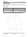
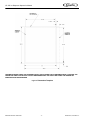
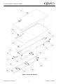
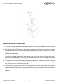
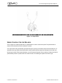
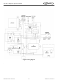
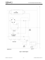
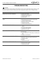
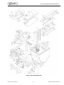
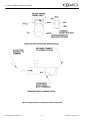
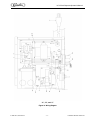
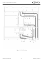
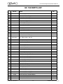
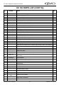
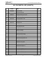
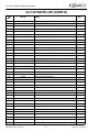
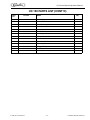
Operator’s Manual
ICE DISPENSER
Model: UC150 ICE ONLY
Release Date: August, 1999
Publication Number: 620917311
Revision Date: March 27, 2014
Revision: D
Visit the Cornelius web site at www.cornelius.com for all your Literature needs.
The products, technical information, and instructions contained in this manual are subject to change without notice.
These instructions are not intended to cover all details or variations of the equipment, nor to provide for every possible contingency in the installation, operation or maintenance of this equipment. This manual assumes that the person(s) working on the equipment have been trained and are skilled in working with electrical, plumbing, pneumatic,
and mechanical equipment. It is assumed that appropriate safety precautions are taken and that all local safety and
construction requirements are being met, in addition to the information contained in this manual.
This Product is warranted only as provided in Cornelius’ Commercial Warrant applicable to this Product and is subject to all of the restrictions and limitations contained in the Commercial Warranty.
Cornelius will not be responsible for any repair, replacement or other service required by or loss or damage resulting
from any of the following occurrences, including but not limited to, (1) other than normal and proper use and normal
service conditions with respect to the Product, (2) improper voltage, (3) inadequate wiring, (4) abuse, (5) accident,
(6) alteration, (7) misuse, (8) neglect, (9) unauthorized repair or the failure to utilize suitably qualified and trained persons to perform service and/or repair of the Product, (10) improper cleaning, (11) failure to follow installation, operating, cleaning or maintenance instructions, (12) use of “non-authorized” parts (i.e., parts that are not 100%
compatible with the Product) which use voids the entire warranty, (13) Product parts in contact with water or the
product dispensed which are adversely impacted by changes in liquid scale or chemical composition.
Contact Information:
To inquire about current revisions of this and other documentation or for assistance with any Cornelius product contact:
www.cornelius-usa.com
800-238-3600
Trademarks and Copyrights:
This document contains proprietary information and it may not be reproduced in any way without permission from
Cornelius.
This document contains the original instructions for the unit described.
CORNELIUS INC
101 Regency Drive
Glendale Heights, IL
Tel: + 1 800-238-3600
Printed in U.S.A.
TABLE OF CONTENTS
Safety Instructions . . . . . . . . . . . . . . . . . . . . . . . . . . . . . . . . . . . . . . . . . . . . . . . . . . . . . . . . . . . . .
Read And Follow All Safety Instructions . . . . . . . . . . . . . . . . . . . . . . . . . . . . . . . . . . . . . . . . .
Safety Overview . . . . . . . . . . . . . . . . . . . . . . . . . . . . . . . . . . . . . . . . . . . . . . . . . . . . . . . .
Recognition. . . . . . . . . . . . . . . . . . . . . . . . . . . . . . . . . . . . . . . . . . . . . . . . . . . . . . . . . . . .
Different Types Of Alerts. . . . . . . . . . . . . . . . . . . . . . . . . . . . . . . . . . . . . . . . . . . . . . . . . . . . .
Safety Tips . . . . . . . . . . . . . . . . . . . . . . . . . . . . . . . . . . . . . . . . . . . . . . . . . . . . . . . . . . . . . . .
Qualified Service Personnel . . . . . . . . . . . . . . . . . . . . . . . . . . . . . . . . . . . . . . . . . . . . . . . . . .
Safety Precautions . . . . . . . . . . . . . . . . . . . . . . . . . . . . . . . . . . . . . . . . . . . . . . . . . . . . . . . . .
Shipping And Storage . . . . . . . . . . . . . . . . . . . . . . . . . . . . . . . . . . . . . . . . . . . . . . . . . . . . . . .
Mounting In Or On A Counter . . . . . . . . . . . . . . . . . . . . . . . . . . . . . . . . . . . . . . . . . . . . . . . . .
1
1
1
1
1
1
1
2
2
2
Description. . . . . . . . . . . . . . . . . . . . . . . . . . . . . . . . . . . . . . . . . . . . . . . . . . . . . . . . . . . . . . . . . . . 3
Specifications . . . . . . . . . . . . . . . . . . . . . . . . . . . . . . . . . . . . . . . . . . . . . . . . . . . . . . . . . . . . . 3
Installation Instructions . . . . . . . . . . . . . . . . . . . . . . . . . . . . . . . . . . . . . . . . . . . . . . . . . . . . . . . . . 5
Cleaning And Maintenance Instructions . . . . . . . . . . . . . . . . . . . . . . . . . . . . . . . . . . . . . . . . . . . .
Daily Cleaning: . . . . . . . . . . . . . . . . . . . . . . . . . . . . . . . . . . . . . . . . . . . . . . . . . . . . . . . . .
Weekly Cleaning: (In Addition To Daily Procedures) . . . . . . . . . . . . . . . . . . . . . . . . . . . .
Monthly Cleaning: (In Addition To Daily And Weekly Procedures). . . . . . . . . . . . . . . . . .
6
6
6
6
Start-up & Operating Instructions . . . . . . . . . . . . . . . . . . . . . . . . . . . . . . . . . . . . . . . . . . . . . . . . . 7
Torsion Bar Removal . . . . . . . . . . . . . . . . . . . . . . . . . . . . . . . . . . . . . . . . . . . . . . . . . . . . . . . 7
Cleaning And Sanitizing Instructions . . . . . . . . . . . . . . . . . . . . . . . . . . . . . . . . . . . . . . . . . . . . . . . 9
Dispenser . . . . . . . . . . . . . . . . . . . . . . . . . . . . . . . . . . . . . . . . . . . . . . . . . . . . . . . . . . . . . . . . 9
1. Cleaning Exterior Surfaces. . . . . . . . . . . . . . . . . . . . . . . . . . . . . . . . . . . . . . . . . . . . . . 9
2. Cleaning Interior Surfaces . . . . . . . . . . . . . . . . . . . . . . . . . . . . . . . . . . . . . . . . . . . . . . 9
Auger Assembly Breakdown . . . . . . . . . . . . . . . . . . . . . . . . . . . . . . . . . . . . . . . . . . . . . . . . . 10
Speed Control For Ice Delivery . . . . . . . . . . . . . . . . . . . . . . . . . . . . . . . . . . . . . . . . . . . . . . . 11
Troubleshooting . . . . . . . . . . . . . . . . . . . . . . . . . . . . . . . . . . . . . . . . . . . . . . . . . . . . . . . . . . . . . 14
Blown Fuse Or Circuit Breaker.. . . . . . . . . . . . . . . . . . . . . . . . . . . . . . . . . . . . . . . . . . . . . . . 14
Agitator Does Not Turn, Auger Does Not Turn. . . . . . . . . . . . . . . . . . . . . . . . . . . . . . . . . . . 14
Ice Dispenses Continuously. . . . . . . . . . . . . . . . . . . . . . . . . . . . . . . . . . . . . . . . . . . . . . . . . . 14
Slushy Ice. Water In Hopper. . . . . . . . . . . . . . . . . . . . . . . . . . . . . . . . . . . . . . . . . . . . . . . . . . 14
Agitator Turns, Auger Does Not Turn. . . . . . . . . . . . . . . . . . . . . . . . . . . . . . . . . . . . . . . . . . . 14
Auger Turns, Agitator Does Not. . . . . . . . . . . . . . . . . . . . . . . . . . . . . . . . . . . . . . . . . . . . . . . 14
UC 150 Parts List. . . . . . . . . . . . . . . . . . . . . . . . . . . . . . . . . . . . . . . . . . . . . . . . . . . . . . . . . . . . . 19
UC 150 Ice Dispenser Operator’s Manual
SAFETY INSTRUCTIONS
READ AND FOLLOW ALL SAFETY INSTRUCTIONS
Safety Overview
•
Read and follow ALL SAFETY INSTRUCTIONS in this manual and any warning/caution labels on the unit (decals, labels or
laminated cards).
•
Read and understand ALL applicable OSHA (Occupational Safety and Health Administration) safety regulations before
operating this unit.
Recognition
Recognize Safety Alerts
!
This is the safety alert symbol. When you see it in this manual or on the unit,
be alert to the potential of personal injury or damage to the unit.
DIFFERENT TYPES OF ALERTS
! DANGER:
Indicates an immediate hazardous situation which if not avoided WILL result in serious injury, death or equipment
damage.
! WARNING:
Indicates a potentially hazardous situation which, if not avoided, COULD result in serious injury, death, or equipment
damage.
! CAUTION:
Indicates a potentially hazardous situation which, if not avoided, MAY result in minor or moderate injury or equipment
damage.
SAFETY TIPS
•
Carefully read and follow all safety messages in this manual and safety signs on the unit.
•
Keep safety signs in good condition and replace missing or damaged items.
•
Learn how to operate the unit and how to use the controls properly.
•
Do not let anyone operate the unit without proper training. This appliance is not intended for use by very young children or
infirm persons without supervision. Young children should be supervised to ensure that they do not play with the appliance.
•
Keep your unit in proper working condition and do not allow unauthorized modifications to the unit.
QUALIFIED SERVICE PERSONNEL
! WARNING:
Only trained and certified electrical, plumbing and refrigeration technicians should service this unit. ALL WIRING AND
PLUMBING MUST CONFORM TO NATIONAL AND LOCAL CODES. FAILURE TO COMPLY COULD RESULT IN
SERIOUS INJURY, DEATH OR EQUIPMENT DAMAGE.
© 1999-2014, Cornelius Inc.
-1-
Publication Number: 620917311
UC 150 Ice Dispenser Operator’s Manual
SAFETY PRECAUTIONS
This unit has been specifically designed to provide protection against personal injury. To ensure continued protection
observe the following:
! WARNING:
Disconnect power to the unit before servicing following all lock out/tag out procedures established by the user. Verify
all of the power is off to the unit before any work is performed.
Failure to disconnect the power could result in serious injury, death or equipment damage.
! CAUTION:
Always be sure to keep area around the unit clean and free of clutter. Failure to keep this area clean may result in
injury or equipment damage.
SHIPPING AND STORAGE
! CAUTION:
Before shipping, storing, or relocating the unit, the unit must be sanitized and all sanitizing solution must be drained
from the system. A freezing ambient environment will cause residual sanitizing solution or water remaining inside the
unit to freeze resulting in damage to internal components.
MOUNTING IN OR ON A COUNTER
! WARNING:
When installing the unit in or on a counter top, the counter must be able to support a weight in excess of 350 lbs. to
insure adequate support for the unit. FAILURE TO COMPLY COULD RESULT IN SERIOUS INJURY, DEATH OR
EQUIPMENT DAMAGE.
NOTE: Many units incorporate the use of additional equipment such as icemakers. When any addition
equipment is used you must check with the equipment manufacturer to determine the additional weight the
counter will need to support to ensure a safe installation.
Publication Number: 620917311
-2-
©1999-2014, Cornelius Inc.
UC 150 Ice Dispenser Operator’s Manual
DESCRIPTION
The Under counter ice dispenser solves your ice service needs in a sanitary, space saving, economical way.
Designed to be manually filled with ice this dispenser will dispense cubes (up to 1-1/4” in size), cube lets and hard
chipped or cracked ice.
SPECIFICATIONS
Model:
UC150
Ice Storage:
150 lbs
Electrical:
Dimensions:
120/1/60, 3 amps total unit draw
30” Wide X 33--5/8” Deep X 27” Below Countertop
16--9/16” High Above Countertop
OPTIONAL: CORIAN COUNTERTOPS ARE ATTACHABLE AND BLEND INTO RESTAURANT DECOR.
(SUPPLIED BY KES). CORIAN IS CUT FROM COUNTER AND FABRICATED (SEE FIGURE 1).
CORIAN IS CUT FROM COUNTER AND IS REWORKED AS SHOWN ABOVE BEFORE BEING GLUED
TO UC 150 DOOR LIDS
Figure 1. Template
© 1999-2014, Cornelius Inc.
-3-
Publication Number: 620917311
UC 150 Ice Dispenser Operator’s Manual
THE ABOVE FIGURE SHOWS THE REQUIRED CUTOUT FOR PLACING THE ICE DISPENSER INTO A COUNTER TOP.
THE DOTTED LINE IS THE ACTUAL CUTOUT DIMENSIONS WHILE THE SOLID LINE SHOWS THE AMOUNT OF
OVERHANG FOR THE DISPENSER.
Figure 2. Dimensions Template
Publication Number: 620917311
-4-
©1999-2014, Cornelius Inc.
UC 150 Ice Dispenser Operator’s Manual
INSTALLATION INSTRUCTIONS
! WARNING:
It is the responsibility of the installer to ensure that the water supply to the dispensing equipment is provided with
protection against backflow by an air gap as defined in ANSI/ASME A112. 1.2-1976; or an approved vacuum breaker
or other such method as proved effective by test and must comply with all federal, state and local codes.
Failure to comply could result in serious injury, death or damage to the equipment.
Water pipe connections and fixtures directly connected to a potable water supply shall be sized, installed, and
maintained according to federal, state and local laws.
1. Locate the dispenser indoors on a level counter top.
A. COUNTER MOUNTING
The ice dispenser must be sealed to the counter. The template drawing indicates the opening that must
be cut in the counter. Locate the desired position for the dispenser, then mark the outline dimensions on
the counter using the template drawings. Cut openings in counter.
Apply a continuous bead of NSF International (NSF) listed silastic sealant (Dow 732 or equal) approximately
1/4” inside of the unit outline dimensions and around all openings. Then, position the unit on the
counter within the outline dimensions. All excess sealant must be wiped away immediately.
2. The drain tube is routed through the large opening in the bottom of the unit. See the MOUNTING TEMPLATE
(page 4) for locating the required clearance hole in the counter for these utility lines. The power cord is routed
through the holes in the side of the unit.
3. SINK DRAIN ASSEMBLY: Connect the drain tube to an open drain. Additional drain tubing is provided with the
unit. The drain tube must continuously pitch downward and contain no “traps” or improper drainage will result.
A. Use 3/4’’ nominal plastic pipe.
B. To assure proper drainage, do not allow “trap” to form in drain line. Be sure drain line runs flat with bottom of
dispenser.
4. Clean the hopper interior (see CLEANING INSTRUCTIONS in Operator’s Manual).
5. Connect the power cord to a 120 volt, 60 cycle, 15-Amp, 3-wire grounded receptacle.
© 1999-2014, Cornelius Inc.
-5-
Publication Number: 620917311
UC 150 Ice Dispenser Operator’s Manual
CLEANING AND MAINTENANCE INSTRUCTIONS
These instructions are used on all Cornelius ice drink dispensers. Some models may have additional cleaning
requirements. Those models will have addition procedures listed later in the manual.
! WARNING:
Disconnect power to the unit before cleaning or servicing following all lock out / tag out procedures established by
the user. Verify all of the power is off to the unit before performing any work.
Failure to comply could result in serious injury, death or damage to the equipment.
! CAUTION:
Do not use metal scrapers, sharp objects or abrasives on the ice storage hopper, top cover, agitator disc or exterior
surfaces as damage to the unit may result. Do not use solvents or other cleaning agents as they may attack the
material resulting in damage to the unit.
Soap solution – Use a mixture of mild detergent and warm (100° F ) potable water.
Sanitizing Solution – Dissolve 2 packets (4 oz) of Stera Sheen Green Label into 2 gallons of warm (80 – 100° F)
potable water to ensure 200 ppm of chlorine.
Daily Cleaning:
1.
Remove cup rest from drip tray and clean with warm soapy water, rinse with clean water and allow to air
dry.
2.
Wipe down the exterior of the unit with warm soapy water, rinse with clean water and allow to air dry.
3.
Clean the interior of the ice chute using the brush provided with the unit with warm soapy water, rinse with
clean water and allow to air dry.
4.
Spray the ice chute inside and out with sanitizer and allow to air dry.
5.
Pour warm soapy water down the drains to keep them clean and flowing smoothly.
6.
Reinstall the cup rest into the drip tray.
7.
Pour all remaining sanitizer solution down the drains to help keep the drain clear.
Weekly Cleaning: (In addition to daily procedures)
Remove the ice chute cover and clean it along with the back half with warm soapy using the brush provided with
the unit. Rinse with clean water and reinstall on the unit. Spray the ice chute assembly with approved sanitizer
allowing it to air dry.
Monthly Cleaning: (In addition to daily and weekly procedures)
1. Remove ice from hopper and clean and sanitize the hopper. (See the Cleaning the interior surfaces section
shown later in this manual).
2. While cleaning the hopper use the brush provided with the unit to clean the cold plate surface. To
accomplish this, the brush needs to be extended through the opening in the bottom of the hopper.
Publication Number: 620917311
-6-
©1999-2014, Cornelius Inc.
UC 150 Ice Dispenser Operator’s Manual
START-UP & OPERATING INSTRUCTIONS
Fill the hopper with ice. Dispense a large cup of ice. Repeat this procedure whenever the dispenser has run out
of ice.
In normal operation, pushing the ice dispenser lever will cause ice to flow from the ice chute. Ice flow will continue
to flow as long as the lever is held depressed. If the dispenser fails to dispense ice, see troubleshooting guide.
TORSION BAR REMOVAL
The hinged door as shipped from the factory is set up for the mounting of Corian on the top. In the case where
Corian will not be used, it is recommended that the rear torsion bar be removed so as to decrease the spring force.
To accomplish this task, the recommended procedure is as follows.
1. Remove balloon Item 46 Ice Deflector by removing the three knurled screws that hold the Ice Deflectory in
place.
2. Break the RTV seal that holds the polymeric inner lid in place. This should be done with a sharp instrument.
3. Gently pry the inner lid out of the stainless steel cover.
4. Now that the complete Torsion Bar Assembly is visible, locate the Counter Balance Pivot which is balloon item
71. Using an 11/32’’ socket or equivalent, remove the two 8-32 hex nuts.
5. Carefully pry the pivot up and away from the mounting studs. As you do this, the torsion shafts will move along
with the pivot.
6. Once the pivot is free of the studs, moving it a little further towards you should allow the torsion shafts to come
free of the pivot.
7. You should be able to grab the rear torsion bar at this time and pull away from the end that is captured in the
sheet metal bracket.
8. Reverse the steps to reassemble the door.
9. RTV liner back in place
© 1999-2014, Cornelius Inc.
-7-
Publication Number: 620917311
UC 150 Ice Dispenser Operator’s Manual
Figure 3. Torsion Bar Removal
Publication Number: 620917311
-8-
©1999-2014, Cornelius Inc.
UC 150 Ice Dispenser Operator’s Manual
CLEANING AND SANITIZING INSTRUCTIONS
Soap solution - Use a mixture of mild detergent and warm (100° F) potable water.
Sanitizing solution - Use 1/2 ounce of household bleach in 1 gallon of potable water. Preparing the sanitizing
solution to this ratio will create a solution of 200 PPM.
DISPENSER
1. CLEANING EXTERIOR SURFACES
IMPORTANT: Perform the following daily.
1.
2.
3.
4.
Remove the cup rest from drip tray.
Wash the drip tray with soap solution. Rinse with potable water and allow solution to run down the drain.
Wash cup rest with soap solution and rinse in potable water. Install the cup rest into the drip tray.
Clean all exterior surfaces with soap solution and rinse with potable water.
2. CLEANING INTERIOR SURFACES
! CAUTION:
When pouring liquid into the hopper, do not exceed the rate of 1/2 gallon per minute.
IMPORTANT: Perform the following at least once a month.
1.
2.
3.
4.
5.
6.
7.
8.
9.
10.
11.
12.
13.
14.
Open right hand hopper cover, then remove all ice from hopper.
Lift up and remove the left hand hopper cover.
Remove agitator disk and agitator assembly.
Remove tower cover by removing three thumb screws.
Move the retaining bail to the rear of the tower which will allow removal of the ice chute assembly.
Grasp the ice auger by the shaft end and lift out the auger tube. Take care not to damage either end of
the auger.
Remove the auger tube by lifting upward. The tube will separate into two halves for easy cleaning when
fully removed.
Open the front door of the cabinet below the hopper, this will give you access to the lower auger drive
area and the passage between the hopper and the auger for cleaning.
Using the previously prepared detergent solution clean the hopper covers, agitator disk, and agitator
assembly, interior of the hopper, both halves of the ice chute, auger, auger tubes, and the lower auger
area of the auger housing. Thoroughly rinse all of the previously cleaned with potable water.
Reassemble the agitator assembly and disc into the hopper. Make certain that the retaining screw is
tight.
Using a mechanical spray bottle filled with sanitizing solution, spray the entire interior of the hopper and
the agitator assembly. Go to the lower auger drive area and also spray with sanitizing solution. Allow to
air dry.
Using the spray bottle, spray the inside of the two halves of the auger tube, the auger, the two halves of
the chute assembly and the undersides of the right and left covers. Allow to air dry.
Reassemble the two halves of the auger tube and place back into its mounting. Holding the auger by
the upper shaft end, insert into the guide tube. Make certain that the auger slips into it drive pin. Chute
assembly will not assemble properly if the auger is not seated on its drive pin. Reassemble the upper
auger and chute assembly onto the auger and lock down by snapping the bail onto the upper housing.
Reinstall the tower cover with the thumb screws.
Reinstall the covers. Put the right cover on first before you close the left cover.
© 1999-2014, Cornelius Inc.
-9-
Publication Number: 620917311
UC 150 Ice Dispenser Operator’s Manual
Figure 4. Auger Assembly
AUGER ASSEMBLY BREAKDOWN
1. For cleaning, the auger assembly is constructed for simple not tools required breakdown. First remove the tower
cap (item 69) by removing the 3 knurled screws.
2. Once the tower cap is out of the way you will see a wire retainer (item 77). By placing your fingers on the backside of the ice chute (item 65) with your thumbs pointing upward, place the thumbs on the retainer wire and with
a slight upward movement push the wire retainer towards the rear of the unit. The retainer should pop out of the
saddle and swing backwards.
3. At this point, you should be able to pull up on the ice chute and remove it from the assembly. You will notice that
the ice chute is made up of three pieces. That is the ice chute, the ice chute cover and the auger gate which is
respectively (Items 65, 66, and 69). Take not so that when reassembling the ice chute, the auger gate cradles in
the ice chute with the short tang side up.
4. The auger (Item 73) can now be removed by just grasping it and pulling up. Notice that the bottom of the auger
has a depression in the form of a D pattern. When replacing the auger, it will be necessary to rotate the auger
after insertion in the tube to engage the motor shaft.
5. Last are the auger housings (Items 74 and 75). They are dislodged by pulling upward. Check their orientation
and the fact that the longer tube is on the front side. When positioning the housings back in the dispenser, the
longer tube should be placed first so as to seat in the lower housing to set up the orientation (top and bottom are
marked on end of the tube tab at the top), otherwise the ice chute spout will not point towards the front of the
dispenser.
Publication Number: 620917311
- 10 -
©1999-2014, Cornelius Inc.
UC 150 Ice Dispenser Operator’s Manual
ARROW SHOWS CCW DIRECTION FOR INCREASING SPEED OF ICE AUGER MOTOR
Figure 5. Ice Auger Motor
SPEED CONTROL FOR ICE DELIVERY
The ice auger is a variable speed device. A potentiometer is used to control this speed. The potentiometer is
located in the electrical box which is below the counter.
The output shaft of the potentiometer protrudes through an opening on the bottom side of the electrical box. For
adjustment the output shaft (Items 62 and 59) is easily reached by removing the left side panel cover (item 42).
By turning the knob CCW (counterclockwise), you will increase the speed of the ice delivery. Please note that the
potentiometer position is upside down so the actual motion for increasing the speed if from left to right
© 1999-2014, Cornelius Inc.
- 11 -
Publication Number: 620917311
UC 150 Ice Dispenser Operator’s Manual
.
Figure 6. Wiring Diagram
.
Publication Number: 620917311
- 12 -
©1999-2014, Cornelius Inc.
UC 150 Ice Dispenser Operator’s Manual
Figure 7. Ladder Diagram
© 1999-2014, Cornelius Inc.
- 13 -
Publication Number: 620917311
UC 150 Ice Dispenser Operator’s Manual
TROUBLESHOOTING
! CAUTION:
Should your unit fail to operate properly, check that there is power to the unit and that the hopper contains ice. If the
unit does not dispense, check the following chart under the appropriate symptoms to aid in locating the defect.
Trouble
Probable Cause
BLOWN FUSE OR CIRCUIT BREAKER.
A.
B.
C.
D.
Short circuit in wiring.
Defective 24 VAC transformer
Defective agitator motor
Shorted motor
AGITATOR DOES NOT TURN, AUGER DOES NOT
A.
B.
C.
D.
E.
F.
No power.
Bent depressor plate (does not actuate switch).
Defective dispensing switch.
Defective interlocks, lids not closed.
Defective timer board
Defective 24 VAC transformer.
TURN.
ICE DISPENSES CONTINUOUSLY.
A. Stuck or bent depressor plate (does not release
switch).
B. Defective dispensing switch.
C. Improper switch installation.
D. Defective timer board.
SLUSHY ICE. WATER IN HOPPER.
A. Blocked drain.
B. Unit not level.
C. Poor ice quality due to water quality or icemaker problems.
D. Improper use of flaked ice.
AGITATOR TURNS, AUGER DOES NOT TURN.
A.
B.
C.
D.
E.
AUGER TURNS, AGITATOR DOES NOT.
A. Defective agitator motor.
B. Defective motor capacitor.
C. Defective timer board.
Publication Number: 620917311
- 14 -
Defective auger motor.
Defective or improper setting of speed control.
Defective rectifier.
Ice jam.
Defective timer board.
©1999-2014, Cornelius Inc.
UC 150 Ice Dispenser Operator’s Manual
Figure 8. US 150 Exploded View
© 1999-2014, Cornelius Inc.
- 15 -
Publication Number: 620917311
UC 150 Ice Dispenser Operator’s Manual
Figure 9. Agitator Motor and Dispense Switch Wiring Detail
Publication Number: 620917311
- 16 -
©1999-2014, Cornelius Inc.
UC 150 Ice Dispenser Operator’s Manual
“A”, “B”, and “C”
Figure 10. Wiring Diagram
© 1999-2014, Cornelius Inc.
- 17 -
Publication Number: 620917311
UC 150 Ice Dispenser Operator’s Manual
Figure 11. UC 150 Plumbing
Publication Number: 620917311
- 18 -
©1999-2014, Cornelius Inc.
UC 150 Ice Dispenser Operator’s Manual
UC 150 PARTS LIST
Item
No
Part No.
1
15087
Retainer, Agitator
1
2
27107
Retainer Lever Ice Disp
1
3
29303R
Plate, Motor Mounting R00
1
4
30514
Saddle Clamp For Capacitor
1
5
30774
Capac Motor Agit 2230AK6
1
6
30794
Heater Agit Mtr 2230AK6
1
7
30895
Actuator Swt 223AK6
1
8
30995
Power Cord Assy R02
1
9
31007
Boot Switch 2230AK6
1
10
31107
Board Term
1
11
31655
Jumper, Blk 3” 16GA
1
12
31945
Jumper, Red 18” 16GA R00
1
13
31981
Actuator Hamlin Magnetic
2
14
620307901
Kit, Agitator Motor, 115 VAC
1
620307902
Kit, Agitator Motor, 220 VAC
1
Name
Qty
15
32682
Transformer Asy 120/25VAC 80VA
1
16
32953
Reed Switch Assy
2
17
32958
Rectifier 10Amp. 800V
1
18
33611
Lead Jump Blk 9”
1
19
33612
Lead Jump Red 9”
1
20
33613
Lead Jump PK 7”
1
21
33614
Lead Jump White 15”
1
22
33616
Lead Jump White 9”
1
23
33617
Harness Wire Motor Agit
1
24
50200
RTV, Dow #732 Clear 10.3 Oz
25
50228
Heat Conductor Compound
26
50279
Tube Insul 1--1/8ID x 3/8W x 6’
27
50326
Insulation Tape 1/8” x 2” x 30
28
50336
Pipe PVC Sch. 40 3/4” x 20’
29
50456
Nylon--Wire Clamp
3
30
50458
Strain Relief Bushing
1
31
50475
Bushing Heyco 7/8
1
32
50573
Snap Bushing 1/2
1
33
50950
Tee -- 3/4
1
34
50951
Ell--90 3/4 SOC x 3/4 SOC
3
35
50952
Adpt--3/4 SOC x 3/4 FPT
2
36
51859
Seal Shaft Motor 2230AK6/DB150
1
37
52132
Adhesive Loctite 242
.001
38
52876
Gasket, Motor Shaft
1
© 1999-2014, Cornelius Inc.
- 19 -
60
48.5
Publication Number: 620917311
UC 150 Ice Dispenser Operator’s Manual
UC 150 PARTS LIST (CONT’D)]
Item
No.
Part No.
39
620024001
Agitator Asy UC Ice Only
1
40
620024305
Brkt Mtr Mtg Auger UC150
1
41
Name
Qty
Obsolete
42
620024307
Panel Cover Elect Box UC150
2
43
620024309
Cabt/Hopper Foamed Asy UC150
1
44
620024310
Ice Fill Cvr Weldment UC150
1
45
620024311
Cover Weldment UC150
1
46
620024316
Ice Deflector UC150
1
47
620024501
Auger Motor Bolt Plate UC150
1
48
620024701
Lever Dispense UC150
1
49
620024702
Tower UC150
1
50
620024705
Access Plate Tower UC150
1
51
620024904
Cover E-Box UC150 McD
1
52
620024913
Spacer Hinge Hopper UC150 McD
1
53
Obsolete
54
620024919
Asy Hinge Shield UC150 McD
1
55
620024920
Asy C/B Brkt UC150 McD
1
56
620024921
Bushing Auger Drive UC150
1
57
629087456
Super Seal Kit (Includes motor, foamed auger housing, seals, and Hardware)
1
N/A
620045952
Auger Motor Mounting Bracket
N/A
620046706
Removable Ice Basket Holder
N/A
620504025
Hinge Cover Assy
N/A
629087428
Tower Base Repair Kit
58
620311701
Agitator Timer (Order Timer Board Update Kit, 629087410, if unit has old
timer board)
1
59
620305204
Knob Rheostat
1
60
620305701
Harness Wire Disp Switch UC150
1
61
620305702
Harness Reed Switch UC150
1
62
620305704
Rheostat Asy
1
63
620503801
Agitator Disk UC150
1
64
620503803
Lower Tube UC
1
65
620504001
Ice Chute Under Counter
1
66
620504002
Ice Chute Cover Under Counter
1
67
620504006
Hopper Conduit Seal
1
68
Hopper Conduit
Seal
Tower Cap UC150 McD
1
69
620504011
Auger Gate UC150 McD
1
70
Publication Number: 620917311
Obsolete
- 20 -
©1999-2014, Cornelius Inc.
UC 150 Ice Dispenser Operator’s Manual
UC 150 PARTS LIST (CONT’D)
Item
No.
Part No.
71
620504020
Pivot C/P UC150
1
72
620504021
Ell 45 PVC Slide x Slip
3
73
620505501
Auger Plastic UC150
1
74
620505701
Asy Auger Housing Front UC150
1
75
620505702
Asy Auger Housing Rear UC150
1
76
620700901
Cup Rest UC Ice Only
1
77
620701104
Ice Chute Retainer UC150
1
78
620701110
Cam C/B UC150
2
79
620701111
Arm C/B Front
1
80
620701112
Hex C/B UC150
2
81
620701114
Arm C/B Rear
1
82
620701115
Roller C/B
1
83
620701117
Latch Asy Bullet UC150
1
84
620906401
Wiring Diagram UC150
1
85
620906404
Label Ice
1
86
70015
Nut Hex 10--32 Keps
2
87
70018
Nut Hex 1/4-20 Keps
4
88
70021
Nut Hex 08--32 SS 18--8
2
89
70023
Nut Hex 04--40 STCA Deps
2
90
70048
Washer SR 225 449 062 STZI INT
4
91
70075
Nut Hex 06-32 STZI Keps
1
92
70076
Nut Hex 08--32 STCA KEPS 1/8
2
93
70085
Nut Acorn 08--32 SS
6
94
70104
Insert THD 08-32 Thin Sht
5
95
70120
Screw MA 10-32 16 GRD
1
96
70134
Screw MA 04-40 RDSL 12
2
97
70147
Screw SM 06 TB RDPH 16 STCA
4
98
70153
Screw MA 06-32 RDPH 14
1
99
70171
8
100
70188
Screw MA 08-32 TRPH 12 SS
Screw WG 08-32 KN 16
101
70204
Screw SM 08 TA TRPH 16 SS
3
102
70215
Screw SM 08 TB HXWS 08
4
103
70217
Screw SM 08 TB HX 16
2
104
70260
Bolt MA 1/4--20 RDPH 32 SS
4
105
70320
Rivet Pop 125D 063-125
10
© 1999-2014, Cornelius Inc.
Name
Qty.
- 21 -
6
Publication Number: 620917311
UC 150 Ice Dispenser Operator’s Manual
UC 150 PARTS LIST (CONT’D)
Item
No.
Part No.
106
70341
Gate Slide Spring
1
107
70847
Spacer SWT 2230
4
108
70959
8-32 STL. PL HEX TSN
4
110
70993
1/4 Turn Retainer
4
111
70994
1/4 Turn Stud Wing Head
4
112
71028
Bolt SH 1/4-20
3
113
90580
Label Elec 115V Brady #CV2C NV
1
114
92067
Label Adjust QFD Agit Timer
1
115
92305
Label Auto Trans
1
116
Name
Qty.
Obsolete
117
620701121
Seal Motor Shaft Auger UC150
1
118
620701119
E Ring Stainless Stl Bullet Latch
1
119
620701120
E Ring Stainless Steel C/B
2
120
50767
Heyco Snap Bushing
3
121
620906403
Wiring Diagram Ladder UC150
1
122
30064
Q C Terminal, 1/4
2
123
50332
PVC Cement
.001
124
50346
E Z Weld Primer--CPVC PVC
.001
125
620701123
Wash Thrust 14GA 9/16 ID SS
1
126
620701122
Wash Spr Curv Disc SS .525ID
1
127
70122
Screw SM 04 TA TRPH 12 SS
2
128
30455
#10 Insul Eyelet Terminal
1
129
620504009
Bucket Ice Fill LP150 McD
1
130
91956
Label Warn Elec Shock
1
131
90432
Label Caution Heater
1
132
620802101
S-Support Pallet 31-1/2 x 36
1
133
620802102
A-Carton 36-1/8 x 31-1/2 x 52-1/8
1
134
620802103
S-in Support 40-3/4 x 36-1/8
2
135
620802104
S-in Support 48 x 31-1/2
1
136
52972
Flush Nylon Clip
1
137
138
Obsolete
620917311
Owner’s Manual
1
140
620508901
Liner Lid RH
1
141
620508902
Liner Lid LH
1
142
620909702
Installation Manual
1
143
80412
Staple 7/8 x 1/4
6
144
80056
Steel Strapping 1/2 x .015
145
80058
Strapping Clip
139
Publication Number: 620917311
- 22 -
190””
1
©1999-2014, Cornelius Inc.
UC 150 Ice Dispenser Operator’s Manual
UC 150 PARTS LIST (CONT’D)
Item
No.
Part No.
146
50418
Plastic Bag
1
147
80333
Corner Protector
2
148
90629
Label Cleaning Caution
1
149
620305705
Motor Harness
1
150
91574
Plate, Identification
1
151
620911201
Label, Corian
3
152
620911202
Label, Speed Control
1
153
620911203
Sht Instl Corian Top
154
53219
N/A
829085201
Door Assy RH Kit
N/A
620048801
Door Assy LH
N/A
620506540
Hinge End Cap
N/A
620503702
Drip Tray
N/A
620024906
Latch Handle Assy
© 1999-2014, Cornelius Inc.
Name
Qty.
Blk Triom 1/32
- 23 -
18
Publication Number: 620917311
Cornelius Inc.
www.cornelius.com


![Installation/Service Manual [ 000995 ]](http://vs1.manualzilla.com/store/data/006030040_1-6e05d98358e67eccf6d1d26ecb5fcb81-150x150.png)