1
Agilent Technologies
87050A Option H15
User’s and Service Guide
Agilent Technologies
87050A Option H15
Multiport Test Set
User’s and Service Guide
Agilent Technologies Part Number: 87050-90029
Printed in USA October 2000
Notices
No part of this manual may be reproduced in any form or by any means
(including electronic storage and retrieval or translation into a foreign
language) without prior agreement and written consent from Agilent
Technologies, Inc. as governed by United States and international
copyright laws.
Restricted Rights Legend
Use, duplication, or disclosure by the U.S. Government is subject to
restrictions as set forth in subparagraph (c)(1)(ii) of the Rights in
Technical Data and Computer Software clause at DFARS 252.227-7013
for DOD agencies, and subparagraphs (c)(1) and (c)(2) of the
Commercial Computer Software Restricted Rights clause at
FAR 52.227-19 for other agencies.
Warranty
The material contained in this document is subject to change without
notice. Agilent Technologies makes no warranty of any kind with
regard to this material, including, but not limited to, the implied
warranties of merchantability and fitness for a particular purpose.
Agilent Technologies shall not be liable for errors contained herein or
for incidental or consequential damages in connection with the
furnishing, performance, or use of this material.
Agilent Technologies, Inc.
1212 Valley House Drive
Rohnert Park, CA 94928-4999, U.S.A.
© Copyright 1998, 2000 Agilent Technologies, Inc.
ii
Contents
1. Agilent Technologies 87050A Option H15
Introduction . . . . . . . . . . . . . . . . . . . . . . . . . . . . . . . . . . . . . . . . . . . . .
Installing the Test Set . . . . . . . . . . . . . . . . . . . . . . . . . . . . . . . . . . . . .
Step 1. Check the Shipment. . . . . . . . . . . . . . . . . . . . . . . . . . . . . . .
Step 2. Meet Electrical and Environmental Requirements . . . . . .
1-2
1-3
1-3
1-4
2. Getting Started
Getting Started . . . . . . . . . . . . . . . . . . . . . . . . . . . . . . . . . . . . . . . . . .
Connecting and Turning on the Test Set . . . . . . . . . . . . . . . . . . . .
Setting the Test Set Address Switch . . . . . . . . . . . . . . . . . . . . . . . .
Performing the Operator’s Check . . . . . . . . . . . . . . . . . . . . . . . . . .
Description. . . . . . . . . . . . . . . . . . . . . . . . . . . . . . . . . . . . . . . . . . .
Equipment Required . . . . . . . . . . . . . . . . . . . . . . . . . . . . . . . . . . .
Process . . . . . . . . . . . . . . . . . . . . . . . . . . . . . . . . . . . . . . . . . . . . . .
2-2
2-2
2-3
2-5
2-5
2-5
2-5
3. The Front and Rear Panels
Front Panel. . . . . . . . . . . . . . . . . . . . . . . . . . . . . . . . . . . . . . . . . . . . . .
Line Power Switch . . . . . . . . . . . . . . . . . . . . . . . . . . . . . . . . . . . . . .
Ports 1–16 . . . . . . . . . . . . . . . . . . . . . . . . . . . . . . . . . . . . . . . . . . . . .
The Transmission and Reflection Ports . . . . . . . . . . . . . . . . . . . . .
The Ground Connector . . . . . . . . . . . . . . . . . . . . . . . . . . . . . . . . . . .
The Port Connection Status LCD . . . . . . . . . . . . . . . . . . . . . . . . . .
Rear Panel . . . . . . . . . . . . . . . . . . . . . . . . . . . . . . . . . . . . . . . . . . . . . .
The Parallel Port Input Connector . . . . . . . . . . . . . . . . . . . . . . . . .
The Parallel Port Output Connector . . . . . . . . . . . . . . . . . . . . . . . .
The Printer/Test Set Switch. . . . . . . . . . . . . . . . . . . . . . . . . . . . . . .
GPIB (HP-IB) Connector . . . . . . . . . . . . . . . . . . . . . . . . . . . . . . . . .
Address Switch . . . . . . . . . . . . . . . . . . . . . . . . . . . . . . . . . . . . . . . . .
Line Module . . . . . . . . . . . . . . . . . . . . . . . . . . . . . . . . . . . . . . . . . . .
Power Cables. . . . . . . . . . . . . . . . . . . . . . . . . . . . . . . . . . . . . . . . . . .
Fuses . . . . . . . . . . . . . . . . . . . . . . . . . . . . . . . . . . . . . . . . . . . . . . . . .
3-2
3-2
3-2
3-3
3-3
3-3
3-4
3-4
3-4
3-4
3-5
3-5
3-5
3-5
3-7
4. Specifications
Specifications . . . . . . . . . . . . . . . . . . . . . . . . . . . . . . . . . . . . . . . . . . . . 4-2
General Characteristics . . . . . . . . . . . . . . . . . . . . . . . . . . . . . . . . . . 4-3
Contents-1
5. Controlling the Test Set and Making Measurements
Introduction . . . . . . . . . . . . . . . . . . . . . . . . . . . . . . . . . . . . . . . . . . . . . 5-2
Commands . . . . . . . . . . . . . . . . . . . . . . . . . . . . . . . . . . . . . . . . . . . . . . 5-3
Computer Control . . . . . . . . . . . . . . . . . . . . . . . . . . . . . . . . . . . . . . . 5-3
Network Analyzer Control . . . . . . . . . . . . . . . . . . . . . . . . . . . . . . 5-5
Calibrating the Test System . . . . . . . . . . . . . . . . . . . . . . . . . . . . . . 5-9
Making Measurements. . . . . . . . . . . . . . . . . . . . . . . . . . . . . . . . . . 5-10
Measuring Transmission . . . . . . . . . . . . . . . . . . . . . . . . . . . . . . 5-10
Measuring Reflection . . . . . . . . . . . . . . . . . . . . . . . . . . . . . . . . . 5-11
Example Program . . . . . . . . . . . . . . . . . . . . . . . . . . . . . . . . . . . . 5-11
The Control Program. . . . . . . . . . . . . . . . . . . . . . . . . . . . . . . . . . 5-12
6. Servicing the Test Set
Performance Testing . . . . . . . . . . . . . . . . . . . . . . . . . . . . . . . . . . . . . . 6-2
Adapter Delay Removal . . . . . . . . . . . . . . . . . . . . . . . . . . . . . . . . . . 6-4
Calibration . . . . . . . . . . . . . . . . . . . . . . . . . . . . . . . . . . . . . . . . . . . . 6-5
Testing for Insertion Loss . . . . . . . . . . . . . . . . . . . . . . . . . . . . . . . . 6-6
Testing for Isolation . . . . . . . . . . . . . . . . . . . . . . . . . . . . . . . . . . . . . 6-7
Testing for Return Loss . . . . . . . . . . . . . . . . . . . . . . . . . . . . . . . . . . 6-8
Performance Test Record. . . . . . . . . . . . . . . . . . . . . . . . . . . . . . . . . . 6-10
Replaceable Parts. . . . . . . . . . . . . . . . . . . . . . . . . . . . . . . . . . . . . . . . 6-17
Troubleshooting the Test Set . . . . . . . . . . . . . . . . . . . . . . . . . . . . . . 6-20
General Troubleshooting Notes . . . . . . . . . . . . . . . . . . . . . . . . . . . 6-20
Troubleshooting Power Supply Problems . . . . . . . . . . . . . . . . . . . 6-20
Troubleshooting the Front Panel Board . . . . . . . . . . . . . . . . . . . . 6-21
Troubleshooting the Controller and Switch Driver Boards . . . . . 6-21
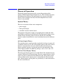
Theory of Operation . . . . . . . . . . . . . . . . . . . . . . . . . . . . . . . . . . . . . . 6-23
System Theory . . . . . . . . . . . . . . . . . . . . . . . . . . . . . . . . . . . . . . . . 6-23
A1 Power Supply Theory. . . . . . . . . . . . . . . . . . . . . . . . . . . . . . . 6-23
A2 Front Panel Display Theory . . . . . . . . . . . . . . . . . . . . . . . . . 6-23
A3 Controller Board (Mother Board) and Switch Driver Board
(Daughter Board) Theory . . . . . . . . . . . . . . . . . . . . . . . . . . . . . . 6-24
Contents-2
Contents
7. Safety and Regulatory Information
Safety and Regulatory Information . . . . . . . . . . . . . . . . . . . . . . . . . .
Introduction . . . . . . . . . . . . . . . . . . . . . . . . . . . . . . . . . . . . . . . . . . .
Safety Information . . . . . . . . . . . . . . . . . . . . . . . . . . . . . . . . . . . . . .
Warnings . . . . . . . . . . . . . . . . . . . . . . . . . . . . . . . . . . . . . . . . . . . .
Cautions . . . . . . . . . . . . . . . . . . . . . . . . . . . . . . . . . . . . . . . . . . . . .
Agilent Technologies Sales and Service Offices . . . . . . . . . . . . . . . . .
7-2
7-2
7-3
7-3
7-4
7-6
Contents-3
Contents-4
1
Agilent Technologies
87050A Option H15
User’s and Service Guide
1-1
Agilent Technologies 87050A Option H15
Introduction
Introduction
The Agilent 87050A Option H15 multiport test set is designed for use
with Agilent Technologies 50 Ω network analyzers such as the
Agilent 871x series, Agilent 8753D, and Agilent 8753E.
The test set provides the ability to make single connection, multiple
measurements of multiport devices with up to 16 ports, such as
distribution amplifiers, taps, switches, and couplers. Measurement
throughput is increased by reducing the number of device reconnects
the operator must perform. Switching is performed by mechanical
switches.
The test set can be controlled by using an external GPIB (HP-IB)
controller, or through parallel control.
NOTE
This user’s and service guide discusses the use of the test set with an
Agilent 8753D or Agilent 8753E only.
For complete theory of operation information on the
Agilent 87050A Option H15, refer to “Theory of Operation” on
page 6-23 in this manual.
1-2
User’s and Service Guide
Agilent Technologies 87050A Option H15
Installing the Test Set
Installing the Test Set
This chapter will guide you through the steps necessary to correctly and
safely install your multiport test set. The steps are:
1. Check the Shipment.
2. Meet Electrical and Environmental Requirements.
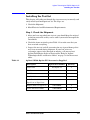
Step 1. Check the Shipment
1. After you have unpacked your test set, you should keep the original
packaging materials so they can be used if you need to transport the
instrument.
2. Check the items received against Table 1-1 to make sure that you
have received everything.
3. Inspect the test set and all accessories for any signs of damage that
may have occurred during shipment. If your test set or any
accessories appear to be damaged or missing, call your nearest
Agilent Technologies Sales or Service office. Refer to “Agilent
Technologies Sales and Service Offices” on page 7-6 for the nearest
office.
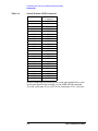
Table 1-1
Agilent 87050A Option H15 Accessories Supplied
Description
Agilent Part Number
Quantity
See Figure 3-3
1
Handle
5063-9228
1
Rack Kit
5063-9235
1
Parallel Cable
8120-6818
1
Semi-Flexible Cable,
8120-6995
2
Adapter, APC-7 to Type-N (f)
85054-60001
2
User's and Service Guide
87050-90029
1
Power Cord
Type-N (m) to Type N (m)
User’s and Service Guide
1-3
Agilent Technologies 87050A Option H15
Installing the Test Set
Step 2. Meet Electrical and Environmental
Requirements
1. The line power module on your test set is an autoranging input. It is
designed to be used with an ac power source with a nominal voltage
of either 115 V or
230 V.
2. Ensure that the available ac power source meets the following
requirements:
90 to 250 Vac, 48 to 66 Hz, 40 W
CAUTION
This product has an autoranging line voltage input. Be sure the supply
voltage is within the specified range.
If the ac line voltage is not within these ranges, use an
autotransformer that provides third-wire continuity to
earth-ground.
3. Ensure that the operating environment meets the following safety
requirements for the following conditions:
• indoor use
• altitude up to 15,000 feet (4,572 meters)
• temperature range of 0° C to 55° C
• maximum relative humidity 80% for temperatures up to 31° C,
decreasing linearly to 50% relative humidity
• enclosure protection, IP 20, according to IEC 529
WARNING
This product is designed for use in INSTALLATION CATEGORY
II, and POLLUTION DEGREE 2, per IEC 101 and 664
respectively.
1-4
User’s and Service Guide
Agilent Technologies 87050A Option H15
Installing the Test Set
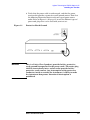
4. Verify that the power cable is not damaged, and that the power
source outlet provides a protective earth-ground contact. Note that
the following illustration depicts only one type of power source
outlet. Refer to Figure 3-3 on page 3-6 to see the different types of
power cord plugs that can be used with your test set.
Figure 1-1
WARNING
Protective Earth Ground
This is a Safety Class I product (provided with a protective
earth-ground incorporated in the power cord). The mains plug
shall be inserted only into a socket outlet provided with a
protective earth contact. Any interruption of the protective
conductor, inside or outside the instrument, is likely to make
the instrument dangerous. Intentional interruption is
prohibited.
User’s and Service Guide
1-5
Agilent Technologies 87050A Option H15
Installing the Test Set
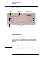
5. Ensure that there are at least two inches of clearance around the
sides and back of the test set and the system cabinet (if used). Refer
to Figure 1-2.
Figure 1-2
CAUTION
Ventilation Clearance Requirements
Ventilation Requirements: When installing the instrument in a cabinet,
the convection into and out of the instrument must not be restricted.
The ambient temperature (outside the cabinet) must be less than the
maximum operating temperature of the instrument by 4° C for every
100 watts dissipated in the cabinet. If the total power dissipated in the
cabinet is greater that 800 watts, then forced convection must be used.
1-6
User’s and Service Guide
Agilent Technologies 87050A Option H15
Installing the Test Set
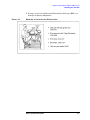
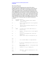
6. Set up a static safe workstation. Electrostatic discharge (ESD) can
damage or destroy components.
Figure 1-3
Example of an Antistatic Workstation
User’s and Service Guide
1-7
Agilent Technologies 87050A Option H15
Installing the Test Set
1-8
User’s and Service Guide
2
Getting Started
User’s and Service Guide
2-1
Getting Started
Getting Started
Getting Started
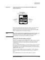
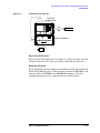
Connecting and Turning on the Test Set
The test set is designed to be placed underneath the network analyzer
in a rack system and connected to it as shown in Figure 2-1 (if you are
using a standard Agilent 8753D/E) or Figure 2-2 on page 2-3 (if you are
using an Agilent 8753D/E Option 011 specifically). Use the two
type-N (m) to type-N (m) semi-flexible cables (Agilent part number
8120-6995) and two APC-7 to type-N (f) adapters (Agilent part number
85054-60001) that were shipped with the test set. Refer to Table 1-1 on
page 1-3.
Figure 2-1
Connecting the Test Set to the Agilent 8753E Network Analyzer
AGILENT 8753E
NETWORK ANALYZER
PORT 1
WITH APC-7 TO
TYPE-N (F) ADAPTER
(P/N 85054-60001)
PORT 2
WITH APC-7 TO
TYPE-N (F) ADAPTER
(P/N 85054-60001)
REFLECTION
TRANSMISSION
AGILENT 87050A OPTION H15
2-2
User’s and Service Guide
Getting Started
Getting Started
Figure 2-2
Connecting the Test Set to the Agilent 8753D Option 011
Network Analyzer
AGILENT 8753D OPTION 011
NETWORK ANALYZER
WITH
AGILENT 85047A S-PARAMETER TEST SET
PORT 1
WITH APC-7 TO
TYPE-N (F) ADAPTER
(P/N 85054-60001)
PORT 2
WITH APC-7 TO
TYPE-N (F) ADAPTER
(P/N 85054-60001)
REFLECTION
TRANSMISSION
AGILENT 87050A OPTION H15
After all the proper connections have been made, turn on the test set
using the front panel line switch. The front panel line switch
disconnects the mains circuits from the mains supply after the EMC
filters and before other parts of the instrument.
NOTE
For accurate, repeatable measurements, be sure to let the test set warm
up for at least 2 hours. It is recommended that the test set not be
turned off on a regular basis. For the most stable and accurate
measurements, leave the test set turned on at all times.
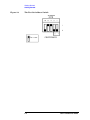
Setting the Test Set Address Switch
The test set is shipped with the GPIB (HP-IB) address set to 12, which
sets the parallel address to 0 as in Figure 2-3 on page 2-4. Refer to
“Introduction” on page 5-2 in this manual for the definition of the
parallel address.
To set the GPIB (HP-IB) address, set all five switches so that the sum of
the switches in the on or 1 position equals the desired address. In the
example below, the two switches in the on position are 8 and 4, thus the
GPIB (HP-IB) address of 12.
To set the parallel address, use only the number 1 switch. Therefore,
the only possibilities for parallel port addressing are an address of
0 or 1.
When GPIB (HP-IB) is used, the parallel address is ignored.
User’s and Service Guide
2-3
Getting Started
Getting Started
Figure 2-3
The Test Set Address Switch
2-4
User’s and Service Guide
Getting Started
Getting Started
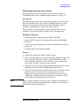
Performing the Operator’s Check
For information on how to control the test set, refer to Chapter 5,
“Controlling the Test Set and Making Measurements,” on page 5-1.
Description
The following operator’s check is designed to provide you with a high
degree of confidence that your test set is working properly. It is not
designed to verify specifications. To verify specifications, refer to
Chapter 4, “Specifications,” on page 4-1 in this manual.
This procedure is for performing a simple operator’s check using a
network analyzer of the proper frequency range and impedance.
Equipment Required
• Network Analyzer, 50 Ω impedance (Agilent 8753D/E)
• Adapter, APC-7 to type-N (f) (Agilent part number 85056-60001),
quantity 2
• Cable, 50 Ω type-N (Agilent part number 8120-6995 or equivalent),
quantity 2
• Calibration Kit, 50 Ω (Agilent 85032B)
Process
1. Connect the 50 Ω cable to Port 1 of the analyzer.
2. On the analyzer, perform a one-port reflection calibration at the end
of the 50 Ω cable over the frequency range of 300 kHz to 6 GHz.
Verify that the calibration is active and that a cable, terminated
with a short, displays a return loss of 0 ±0.2 dB.
3. Connect the cable (already connected to Port 1 of the analyzer) to the
reflection port of the Agilent 87050A Option H15 test set.
4. Using the network analyzer, measure the return loss of each section
of the test set by selecting ports 1 through 16, one at a time.
Terminate each port being tested with a 50 Ω load (greater than
–30 dB). The resulting return loss should be greater than –12 dB
(the absolute value should be greater than 12).
NOTE
This is an 80% confidence test only. A unit could pass this simple test
and yet still not function properly. For more complete testing, refer to
“Performance Testing” on page 6-2.
User’s and Service Guide
2-5
Getting Started
Getting Started
2-6
User’s and Service Guide
3
The Front and Rear Panels
This chapter contains information about the ports and switches found
on the front and rear panels of the test set. This chapter is divided into
two sections: front panel and rear panel.
User’s and Service Guide
3-1
The Front and Rear Panels
Front Panel
Front Panel
Figure 3-1
Front Panel
Reflection
(Type-N)
Transmission
(Type-N)
Ports 1 - 16
(SMA)
Line Power Switch
Port Connection
Status
Ground Connector
Line Power Switch
The test set line power switch is located at the bottom left corner of the
front panel. See Figure 3-1. The line power switch turns the power to
the test set either on or off.
The front panel line switch disconnects the mains circuits from the
mains supply after the EMC filters and before other sections of the
instrument.
Ports 1–16
Ports 1 through 16 are 50 Ω SMA connectors that are used to connect to
the device under test.
CAUTION
Do not input more than 1 watt (RF and DC combined) to these ports, or
damage to the internal RF switches or the analyzer may occur.
3-2
User’s and Service Guide
The Front and Rear Panels
Front Panel
The Transmission and Reflection Ports
The transmission and reflection ports are 50 Ω type-N connectors. A
50 Ω cable connects directly to the Reflection/Transmission port or Port
1/Port 2 of the network analyzer by means of the cables
(Agilent part number 8120-6995) and adapters (Agilent part number
85054-60001) that were shipped with your test set.
CAUTION
Check your analyzer documentation for power levels above which the
ports can be damaged. Make sure that your test setup will not cause
those levels to be exceeded.
The Ground Connector
The ground connector on the front panel provides a convenient ground
connection for a standard banana plug.
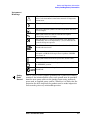
The Port Connection Status LCD
The port connection status LCD provides visual feedback of which
port(s) are connected to the Transmission and Reflection ports of the
test set. When the LCD displays a path connection, all other
corresponding test ports are internally terminated in 50 Ω.
User’s and Service Guide
3-3
The Front and Rear Panels
Rear Panel
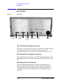
Rear Panel
Figure 3-2
Rear Panel
Parallel Port
Input
Parallel Port
Output
Printer
Test Set
Switch
GPIB
Connector
Address
Switch
Line
Module
The Parallel Port Input Connector
This input is connected to the network analyzer. The analyzer provides
control signals that drive the switches inside the test set. In
pass-through mode, it also accepts signals required to drive a printer.
The Parallel Port Output Connector
The output from this connector is used either to control another test set,
or to control a printer, depending upon how the Printer/Test Set switch
is set.
The Printer/Test Set Switch
This switch determines the function of the Parallel Port Output
connector. When switched to Printer, the Parallel Port Output will
pass-through printer driver signals. When switched to Test Set, an
additional test set can be controlled from the Parallel Port Output
connector.
3-4
User’s and Service Guide
The Front and Rear Panels
Rear Panel
GPIB (HP-IB) Connector
This connector allows the test set to be connected directly to a controller
that uses GPIB (HP-IB) commands. Refer to “Controlling the Test Set,”
Figure 5-3 on page 5-11.
Address Switch
The address switch sets either the GPIB (HP-IB) or the parallel address
of the test set. See “Setting the Test Set Address Switch” on page 2-3 for
information.
Line Module
The line module contains the power cable receptacle and the line fuse.
The line module is an autoranging input and is designed to be used
with an ac power source having a nominal voltage of either 115 V or
230 V. For fuse replacement information, refer to the section “Fuses” on
page 3-7.
Power Cables
The line power cable is supplied in one of several configurations,
depending on the destination of the original shipment.
Each instrument is equipped with a three-wire power cable. When
connected to an appropriate ac power receptacle, this cable grounds the
instrument chassis. The type of power cable shipped with each
instrument depends on the country of destination. Refer to “Power
Cable and Line (Mains) Plug Part Number,” Figure 3-3 on page 3-6 for
the part numbers of these power cables. Cables are available in
different lengths. Check with your nearest Agilent Technologies service
center for descriptions and part numbers of cables other than those
described in Figure 3-3. Refer to “Agilent Technologies Sales and
Service Offices” on page 7-6 for the location closest to you.
CAUTION
Always use the three-prong ac power cord supplied with this product.
Failure to ensure adequate grounding by not using this cord may cause
damage to the product.
WARNING
This is a Safety Class I product (provided with a protective
earth-ground incorporated in the power cord). The mains plug
shall be inserted only into a socket outlet provided with a
protective earth contact. Any interruption of the protective
conductor, inside or outside the instrument, is likely to make
the instrument dangerous. Intentional interruption is
prohibited.
User’s and Service Guide
3-5
The Front and Rear Panels
Rear Panel
Figure 3-3
Power Cable and Line (Mains) Plug Part Number
a
Plug Type
250V
Cable
Part
Number
Plug b
Length
Description cm (in.)
Cable
Color
8120-8705
Straight
BS 1363A
229 (90)
Mint Gray
8120-8709
90
229 (90)
Mint Gray
8120-1369
Straight
AS 3112
210 (79)
Gray
8120-0696
90
200 (78)
Gray
8120-1378
Straight
NEMA 5-15P
203 (80)
Jade Gray
8120-1521
90
203 (80)
Jade Gray
8120-4753
Straight
NEMA 5-15P
229 (90)
Gray
8120-4754
90
229 (90)
Gray
8120-1689
Straight
CEE 7/VII
200 (78)
Mint Gray
E
L
N
250V
E
L
N
125V
E
N
L
125V
For Use
in Country
Option 900
United Kingdom, Hong
Kong, Cyprus, Nigeria,
Singapore, Zimbabwe
Option 901
Argentina, Australia,
New Zealand, Mainland
China
Option 903
United States, Canada,
Brazil, Colombia,
Mexico,Philippines,
Saudi Arabia, Taiwan
Option 918
Japan
E
N
L
250V
E
N
L
230V
8120-1692
90
200 (78)
Mint Gray
8120-2104
Straight
SEV Type 12
200 (78)
Gray
8120-2296
90
200 (78)
Gray
8120-2956
Straight
SR 107-2-D
200 (78)
Gray
8120-2957
90
200 (78)
Gray
8120-4211
Straight
IEC 83-B1
200 (78)
Mint Gray
Option 902
Continental Europe,
Central African Republic,
United Arab Republic
Option 906
Switzerland
E
L
N
220V
N
L
Option 912
Denmark
E
250V
Option 917
South Africa, India
E
L
N
250V
8120-4600
90
200 (78)
Mint Gray
8120-5182
Straight
SI 32
200 (78)
Jade Gray
8120-5181
90
200 (78)
Jade Gray
Option 919
Israel
E
N
L
a. E =earth ground, L = line, and N = neutral.
b. Plug identifier numbers describe the plug only. The Agilent Technologies part number is for the complete cable assembly.
3-6
User’s and Service Guide
The Front and Rear Panels
Rear Panel
Fuses
The line fuse and a spare reside within the line module.
Figure 3-4 illustrates where the fuses are and how to access them.
Available Fuses
United States (115 V orientation)
• Fuse (F 3 A/250 V, Agilent part number 2110-0780), U.L. listed and
CSA certified.
Europe (230 V orientation)
• Fuse (F 3.15 A/250 V, Agilent part number 2110-0655), IEC certified
and U.L. recognized.
Figure 3-4
Location of Line Fuse
User’s and Service Guide
3-7
The Front and Rear Panels
Rear Panel
3-8
User’s and Service Guide
4
Specifications
User’s and Service Guide
4-1
Specifications
Specifications
Specifications
Table 4-1
Agilent 87050A Option H15 Specifications
Parameter
Frequency Range
Specification
300 kHz to 6.0 GHz
Insertion Loss
300 kHz up to 1.3 GHz
≤1.5 dB
1.3 GHz up to 3.0 GHz
≤1.75 dB
3.0 GHz to 6.0 GHz
≤2.5 dB
Return Loss (Switch Path ON)
300 kHz up to 1.3 GHz
≥25 dB
1.3 GHz up to 3.0 GHz
≥16 dB
3.0 GHz to 6.0 GHz
≥12 dB
Return Loss (Switch Path OFF)
300 kHz up to 1.3 GHz
≥26 dB (typical)
1.3 GHz up to 3.0 GHz
≥21 dB (typical)
3.0 GHz to 6.0 GHz
≥15 dB (typical)
Isolationa
300 kHz up to 3.0 GHz
≥100 dB
3.0 GHz to 6.0 GHz
≥90 dB
Input Power Damage Level
>1 watt (RF+DC)
a. From Port to Port (1 through 16)
4-2
User’s and Service Guide
Specifications
Specifications
General Characteristics
Table 4-2
Environmental Characteristics
General Conditions
ESD (electrostatic discharge) must be eliminated by means of static-safe work procedures and
an antistatic workstation such as that illustrated in Figure 1-3 on page 1-7
Operating Environment (for indoor use only)
Altitude
up to 15,000 feet (4,572 meters)
Operating Temperature
0° C to 55° C
Maximum Relative Humidity
80% for temperatures up to 31° C, decreasing linearly to
50% relative humidity at 40° C
Enclosure protection IP 20, according to IEC 529
This product is designed for use in INSTALLATION CATEGORY II, and POLLUTION
DEGREE2, per IEC 101 and 664, respectively.
Nonoperating Storage Conditions
Temperature
–40° C to 70° C
Humidity
0 to 90% relative at 65° C (noncondensing)
Altitude
0 to 15,240 meters (50,000 feet)
Weight
Net: approximately 9 kg
Shipping: approximately 20 kg
Cabinet Dimensions
178 mm H by 425 mm W by 500 mm D
(These dimensions exclude front
and rear panel protrusions)
(7.02 in. by 16.75 in. by 19.7 in.)
Figure 4-1
Agilent 87050A Option H15 Physical Dimensions
If you need technical assistance, contact the nearest Agilent
Technologies sales or service office. Refer to “Agilent Technologies Sales
and Service Offices” on page 7-6 for the location closest to you.
User’s and Service Guide
4-3
Specifications
Specifications
4-4
User’s and Service Guide
5
Controlling the Test Set and Making
Measurements
User’s and Service Guide
5-1
Controlling the Test Set and Making Measurements
Introduction
Introduction
The Agilent 87050A Option H15 is a “slave” instrument: a controller
must be used to control the test set. There are three ways in which the
test set can be controlled:
1. The controller can communicate to the network analyzer using GPIB
(HP-IB) commands, which then controls the test set by the parallel
connection.
2. The controller can control the test set directly by GPIB (HP-IB)
commands.
3. A network analyzer equipped with a parallel connection can control
the test set directly.
5-2
User’s and Service Guide
Controlling the Test Set and Making Measurements
Commands
Commands
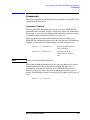
These three methods of control and their commands are detailed below
and on the following pages.
Computer Control
The first method of controlling the test set is to write GPIB (HP-IB)
commands to the network analyzer, which then writes the command to
the test set by way of the parallel port. The following examples use the
variable D, which is defined in Table 5-1 on page 5-6.
To use a parallel port connection with the Agilent 8753D,E, use an
GPIB (HP-IB) command to write bits on the parallel port. The following
example assumes that the address of the network analyzer is 16.
NOTE
OUTPUT 716;"PARALGPIO;"
Sets the parallel port for
GP-IO function
OUTPUT 716;"PARAOUT[D];"
Programs all GP-IO
output bits (0 to 256) at
once
Be sure to use the ending semicolon.
The second method of controlling the test set is to address the Agilent
87050A Option H15 test set directly over GPIB (HP-IB), using a
controller to write directly to the test set's GPIB (HP-IB) port. See
Figure 5-1 on page 5-4 for a diagram of connections for this type of
control. The following example assumes that the address of the test set
is 12.
OUTPUT 712;"command$"
User’s and Service Guide
5-3
Controlling the Test Set and Making Measurements
Commands
Figure 5-1
Controlling the Test Set Over GPIB (HP-IB)
AGILENT 8753E
NETWORK ANALYZER
GPIB
CONTROLLER
AGILENT 87050A OPTION H15
NOTE
It is not necessary to have the test set connected to the network
analyzer when you are controlling the test set over GPIB (HP-IB).
5-4
User’s and Service Guide
Controlling the Test Set and Making Measurements
Commands
Network Analyzer Control
The third method of sending commands uses the network analyzer to
control the test set directly. This method is performed with the
standard setup of the network analyzer working with the test set. A
parallel cable is connected from the network analyzer parallel output to
the test set parallel input on the rear panels of both instruments.
NOTE
The following key conventions are used throughout this document.
• [HARDKEYS] are labeled keys on the instrument front panel.
• SOFTKEYS are unlabeled keys whose function is defined on the
instrument display.
• Information shown on the instrument display is shown LIKE THIS.
The key labels can be either upper case or lower case.
1. Press [SEQ] > TTL IO > PARALLEL OUT ALL.
2. Use the arrow keys, ↑=or ↓=to scroll to the desired test port address,
or input the number directly using the [D] > [x1], where D represents
the decimal value of the test port address.
Refer to Table 5-1 on page 5-6.
User’s and Service Guide
5-5
Controlling the Test Set and Making Measurements
Commands
Table 5-1
Test Port Addresses
Connection Path
Decimal
[D]
Binary
Equivalent
GPIB
(HP-IB)
Command
Reflection to Port 1
0
00000000
refl_01
Reflection to Port 2
1
00000001
refl_02
Reflection to Port 3
2
00000010
refl_03
Reflection to Port 4
3
00000011
refl_04
Reflection to Port 5
4
00000100
refl_05
Reflection to Port 6
5
00000101
refl_06
Reflection to Port 7
6
00000110
refl_07
Reflection to Port 8
7
00000111
refl_08
Reflection to Port 9
8
00001000
refl_09
Reflection to Port 10
9
00001001
refl_10
Reflection to Port 11
10
00001010
refl_11
Reflection to Port 12
11
00001011
refl_12
Reflection to Port 13
12
00001100
refl_13
Reflection to Port 14
13
00001101
refl_14
Reflection to Port 15
14
00001110
refl_15
Reflection to Port 16
15
00001111
refl_16
Reflection Terminated
16
00010000
j18-2
Transmission to Port 1
17
00010001
tran_01
Transmission to Port 2
18
00010010
tran_02
Transmission to Port 3
19
00010011
tran_03
Transmission to Port 4
20
00010100
tran_04
Transmission to Port 5
21
00010101
tran_05
Transmission to Port 6
22
00010110
tran_06
Transmission to Port 7
23
00010111
tran_07
Transmission to Port 8
24
00011000
tran_08
Transmission to Port 9
25
00011001
tran_09
Transmission to Port 10
26
00011010
tran_10
Transmission to Port 11
27
00011011
tran_11
Transmission to Port 12
28
00011100
tran_12
Transmission to Port 13
29
00011101
tran_13
Transmission to Port 14
30
00011110
tran_14
Transmission to Port 15
31
00011111
tran_15
Transmission to Port 16
32
00100000
tran_16
Transmission Terminated
33
00100001
j19-2
All Ports Terminated into 50 Ω
34
00100010
*all_term
Reset, Reflection-Port 1 and
Transmission-Port 2
35
00100011
*rst
Serial Number
5-6
sn?
User’s and Service Guide
Controlling the Test Set and Making Measurements
Commands
To connect all ports to their internal 50 Ω loads, send the following
command:
OUTPUT 712;"*all_term;"
NOTE
When a test set port is not in use, it is terminated in 50 Ω.
If the Agilent 87050A Option H15 is being controlled by GPIB (HP-IB),
you can read the serial number of the test set by sending the following
commands:
OUTPUT 712;"sn?"
ENTER 712:Sn$
DISP Sn$
When the RESET command is sent, the test set is set to a known state
where the Reflection port is directed to Port 1 and the Transmission
port is directed to Port 2.
Refer to the Option H15 block diagram, Figure 6-1 on page 6-22, for the
switch paths.
The switch count represents the number of times each switch has been
activated. To read the individual switch count, send the following
command:
OUTPUT 712;"SW11?"
ENTER 712; COUNT$
DISP COUNT$
The above example shows the SW11 command only. To enter additional
commands use Table 5-2 on page 5-8.
User’s and Service Guide
5-7
Controlling the Test Set and Making Measurements
Commands
Table 5-2
Switch Number GPIB Command
Switch Number
GPIB (HP-IB)
Command
S10
SW10?
S11
SW11?
S12
SW12?
S14
SW14?
S15
SW15?
S16
SW16?
S18
SW18?
S19
SW19?
S51
SW51?
S53
SW53?
S55
SW55?
S57
SW57?
S62
SW62?
S63
SW63?
S64
SW64?
S65
SW65?
S66
SW66?
S67
SW67?
S68
SW68?
S69
SW69?
S70
SW70?
S71
SW71?
S72
SW72?
S74
SW74?
To enter commands for activating each switch port individually, use the
switch-port identifier. For example, use the GPIB (HP-IB) command
J18-2 for switch-port J18-2, and J51-1 for switch-port J51-1, and so on.
5-8
User’s and Service Guide
Controlling the Test Set and Making Measurements
Commands
Calibrating the Test System
After the test set has warmed up for at least two hours, you should
calibrate it before making any measurements. Refer to your network
analyzer user’s guide to determine the type of calibration appropriate
for the measurements you will be making.
You will need to calibrate each measurement path separately and store
the calibration as an instrument state in the network analyzer. Refer to
your network analyzer user’s guide for information on how to calibrate
and store instrument states.
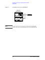
Refer to Figure 5-2. In this example setup the following tests will be
made:
• Return loss on the DUT's input and two output ports (A and B)
• Insertion loss (or gain) between the DUT's input and port A
• Insertion loss (or gain) between the DUT's input and port B
Figure 5-2
Calibrating the Test System
AGILENT 8753E
NETWORK ANALYZER
AGILENT 87050A OPTION H15
CALIBRATION
PATHS
A
OUT
B
DUT
IN
For the best accuracy, you should perform a full two-port calibration
between test set ports 1 and 2, and again between ports 1 and 3. As
mentioned before, you need to save the calibrations as instrument
states. See your analyzer user's guide for information on calibrations
and saving instrument states.
CAUTION
When performing a full two-port calibration and making subsequent
measurements, you must use the transfer switch internal to the
Agilent 8753D/E to change the direction of the RF signal path. Do not
use the test set to change the direction of the RF signal path when you
are using a full two-port calibration. Doing so will render the
calibration invalid.
User’s and Service Guide
5-9
Controlling the Test Set and Making Measurements
Commands
Making Measurements
The following examples assume that you are using a parallel port
connection with an Agilent 8753D/E, with the test set parallel address
set to 0. Refer to “Setting the Test Set Address Switch” on page 2-3, for
information on setting the test set address.
Measuring Transmission
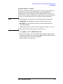
Refer to Figure 5-3 on page 5-11 for the following discussion. With the
Agilent 8753D/E set to measure forward transmission (S21), the
analyzer RF source is being output through the analyzer Port 1, and
Port 2 is set to receive the RF signal.
By using the following commands, you will connect Port 3 of the test set
to the Reflection port, and you will connect Port 7 of the test set to the
Transmission port. You will thus be measuring forward transmission
through the device under test when measuring S21. This will provide
you with gain or insertion loss information.
OUTPUT 716;"PARALGPIO;"
OUTPUT 716;”PARAOUT2;”
OUTPUT 716;”PARALGPIO;”
OUTPUT 716;”PARAOUT6;”
If controlling the Agilent 87050A Option H15 directly, use the following
GPIB (HP-IB) commands:
OUTPUT 712;"refl_03"
ENTER 712;”tran_07”
5-10
User’s and Service Guide
Controlling the Test Set and Making Measurements
Commands
Figure 5-3
Controlling the Test Set
AGILENT 8753E
NETWORK ANALYZER
PARALLEL
PORT
GPIB
CONTROLLER
AGILENT 87050A OPTION H15
PARALLEL
PORT INPUT
DUT
IN
OUT
Measuring Reflection
By leaving the DUT connected as in Figure 5-3, and setting the network
analyzer to measure S11, you can measure reflection or return loss.
Example Program
An example program for making measurements is briefly described and
listed on the following pages. This program is written in HP BASIC and
is for use with an HP 9000 series 200/300/700 computer. Use this
example program to create a program for your specific needs.
User’s and Service Guide
5-11
Controlling the Test Set and Making Measurements
Commands
The Control Program
The Control program demonstrates the control of the Agilent
87050A Option H15 by GPIB (HP-IB) commands or the parallel port.
This program can be used to select any port combination manually
(listed on the following pages). This program will first ask the user
which method will be used to control the Agilent 87050A Option H15,
either GPIB (HP-IB) or parallel port. It will then ask which ports are to
be enabled. The port entries are done in pairs (reflection/transmission)
with the two numbers separated by a comma. The numbers may range
from 0 through 16 for the test ports. For example, an entry of 2,5 will
connect the Reflection port to Port 2 and the Transmission port to Port
5. The program is a continuous loop. Press STOP to end program
execution.
10
! RE-SAVE "control"
20
! CONTROL:
30
!
Agilent 87050A Option H15 via the parallel
port of the
40
!
Agilent 8753D,E network analyzer or via
GPIB directly.
50
!
60
! NOTE:
You MUST select either GPIB control or
Parallel Port
70
!
control. If Parallel Port via the Agilent
8753D,E is
80
!
selected, this program will return the
analyzer to
90
!
LOCAL control after the switches are set.
100
!
110
!
120
!
130
!
The Agilent 87050A Option H15 can be set to
one of two
140
!
Parallel Port addresses.
Set_switches)
150
!
160
!
170
Alto,
!
5-12
This example program allows "manual"
control of the
Set the GPIB address as required below.
This program (SUB
assumes it is set to address 00.
Copyright: Agilent Technologies Co. Palo
CA 94304
User’s and Service Guide
Controlling the Test Set and Making Measurements
Commands
180
!
190
!
200
!
210
Nwa_addr=716
220
Ts_addr=712
230
!
240
CLEAR SCREEN
250
PRINT USING "3/,K,/";"*****
FOR Agilent 87050A-H15
260
PRINT "Either direct GPIB control of the Agilent
87050A-H15 may be selected (h),"
270
PRINT "or indirect control via the Parallel Port (p)
of the Agilent 8753D,E"
280
REPEAT
Developed at Microwave Instruments Division
Santa Rosa, CA
Revision A.01.00
05 May 1998
DEMONSTRATION PROGRAM
MANUAL CONTROL
*****"
290
Answ$="p"
300
OUTPUT 2;Answ$&CHR$(255)&"H";
310
BEEP 300,.1
320
INPUT "Select desired test-set control.
Parallel Port? (Enter H or P)",Answ$
330
Answ$=UPC$(Answ$[1,1])
340
UNTIL Answ$="P" OR Answ$="H"
350
Controller$=Answ$
360
!
370
ABORT 7
380
CLEAR SCREEN
390
IF Controller$="P" THEN
400
Addr=Nwa_addr
410
420
rm
GPIB or
! Assign address to the analyzer
PRINT "Test set is being controlled via Parallel
Port; Agilent 8753D,E address =";Addr
ELSE
430
Addr=Ts_addr
440
PRINT "Test set is being controlled directly via
GPIB. GPIB address =";Addr
450
END IF
460
Isc=Addr DIV 100
User’s and Service Guide
! Interface Select Code
5-13
Controlling the Test Set and Making Measurements
Commands
470
!
480
PRINT USING "/,K,/";RPT$("-",77)
490
PRINT "For manual operation of this switch box, enter
TWO numbers separated by"
500
PRINT "a comma (,). The two numbers represent the
port numbers directed to the"
510
PRINT "Reflection Port and Transmission Port,
respectively. Setting a port to"
520
PRINT "'0' will terminate the corresponding port."
530
PRINT "Unless both numbers are '0', the two values
cannot be the same."
540
PRINT "To terminate the program, press STOP or PAUSE."
550
PRINT
560
PRINT "Example: 1,2 sets the test set paths Port 1 to
Reflection Port and"
570
PRINT " Port 2 to Transmission Port."
580
PRINT " 10,1 sets the test set paths Port 10 to
Reflection Port and"
590
PRINT " Port 1 to Transmission Port."
600
PRINT " 0,5 sets the test set paths Reflection Port
terminated and"
610
PRINT " Port 5 to Transmission Port."
620
PRINT "
0,0 sets the test set paths to
terminate both Reflection and"
630
PRINT " Transmission ports."
640
PRINT " all_term
all ports"
650
PRINT " reset sets the test set to known paths, i.e.,
Reflection Port"
660
PRINT " to Port 1 and Transmission Port to Port 2."
670
PRINT
680
PRINT "If you have selected GPIB you may also check
the serial number of"
690
PRINT "the unit by typing 'serial', or check the
number of times the switch"
700
PRINT "has switched by typing 'switch ##', where ## is
the number of the"
710
PRINT "desired switch."
5-14
sets the test set paths to terminate
User’s and Service Guide
Controlling the Test Set and Making Measurements
Commands
720
LOOP
730
Refl=0
740
Trans=0
750
BEEP 500,.1
760
LINPUT "Enterthe Reflection Port/Transmission Port
selections separated by commas: e.g. 1,2
",Command$
770
Current_pos=POS(Command$,",")
780
Command_length=LEN(Command$)
790
Counter=0
800
Cmd$=Command$
810
IF Current_pos>0 THEN
820
WHILE Current_pos>0
830
Command_length=LEN(Command$)
840
Current$=Command$[1,(Current_pos-1)]
850
Command$=Command$[(Current_pos+1),Command
_length]
860
Current_pos=POS(Command$,",")
870
Set_no=VAL(Current$)
880
SELECT Counter
890
CASE 0
900
910
Refl=Set_no
CASE ELSE
920
PRINT TABXY(1,29),"Too many numbers
entered. Try again! Entered ";Cmd$
930
BEEP 500,.1
940
WAIT 1
950
END SELECT
960
Counter=Counter+1
970
END WHILE
980
Set_no=VAL(Command$)
990
Trans=Set_no
1000
PRINT TABXY(1,29),"
1010
"
IF NOT (((Refl<>Trans) OR (Refl=0 AND Trans=0)
OR (Trans=16 AND Refl=16)) AND Refl<17 AND
Trans<17 AND Refl>=0 AND Trans>=0) THEN
User’s and Service Guide
5-15
Controlling the Test Set and Making Measurements
Commands
1020
DISP "Port selections MUST be different if
non-zero; Range= 0 to 16.
Entered """&Current$&","&Command$&""""
1030
BEEP 1500,.3
1040
WAIT 5
1050
ELSE
1060
Set_switches(Addr,"REFL",VAL$(Refl),
Controller$)
1070
! Sets Ports
1080
Set_switches(Addr,"TRANS",VAL$(Trans),
Controller$)
1090
! Sets Ports
1100
PRINT TABXY(1,28),"
1110
PRINT TABXY(1,28),"Current Port = ";Refl;"
to Reflection Port"
1120
PRINT TABXY(1,29),"
1130
"
PRINT TABXY(1,29),"Current Port = ";Trans;"
to Transmission Port"
1140
1150
"
END IF
ELSE
1160
SELECT UPC$(Command$)
1170
CASE "SERIAL"
1180
OUTPUT 712;"sn?"
1190
ENTER 712;Sn$
1200
PRINT TABXY(1,29),"
1210
PRINT TABXY(1,29),"serial number is ";Sn$
1220
1230
"
CASE "ALL_TERM"
IF Controller$="H" THEN
1240
Output_cmd$="*all_term"
1250
OUTPUT Addr;Output_cmd$
1260
ELSE
1270
Output_cmd$="34"
1280
OUTPUT Addr;"PARALGPIO;"
1290
OUTPUT Addr;"PARAOUT"&Output_cmd$&";"
1300
END IF
1310
PRINT TABXY(1,28),"
5-16
"
User’s and Service Guide
Controlling the Test Set and Making Measurements
Commands
1320
1330
1340
1350
PRINT TABXY(1,29),"
PRINT TABXY(1,28),"All ports are terminated
into 50 ohms."
CASE "RESET"
IF Controller$="H" THEN
1360
Output_cmd$="*rst"
1370
1380
"
OUTPUT Addr;Output_cmd$
sent via GPIB
!
ELSE
1390
Output_cmd$="35"
1400
OUTPUT Addr;"PARALGPIO"
1410
OUTPUT Addr;"PARAOUT"&Output_cmd$&";"!
sent via Centronics Port
1420
END IF
1430
PRINT TABXY(1,28),"
"
1440
PRINT TABXY(1,29),"
"
1450
PRINT TABXY(1,28),"Test set reset; Port 1
to REFL & Port 2 to TRANS."
1460
CASE ELSE
1470
Command$=UPC$(Command$)
1480
IF POS(Command$,"SWITCH") THEN
1490
Nu$=TRIM$(Command$[8,Command_length])
1491
SELECT Nu$
1492
CASE "10","11", "12", "14","15", "16",
"18", "19", "51", "53", "55", "57",
"62" TO "72", "74"
1510
OUTPUT 712;"sw"&Nu$;"?"
1520
ENTER 712;Count$
1530
PRINT TABXY(1,30),"
1540
PRINT TABXY(1,30),"switch number
";Nu$;" has ";Count$
1550
CASE ELSE
1560
DISP
10,
51,
Try
1570
User’s and Service Guide
"
"Installed switch numbers are
11, 12, 14, 15, 16, 18, 19,
53, 55, 57, 62 thru 72 and 74.
again! Entered ";Command$
BEEP 300,.1
5-17
Controlling the Test Set and Making Measurements
Commands
1580
WAIT 3
1590
END SELECT
1600
ELSE
1610
DISP "Unknown command """;Command$;""""
1620
BEEP 300,.1
1630
WAIT 3
1640
END IF
1650
END SELECT
1660
END IF
1670
END LOOP
1680
END
1690
!
1700
SUB Set_switches(Addr,First_parm$,Second_parm$, Contr
oller$)
1710
!====================================================
1720
! PURPOSE:To set the Agilent 87050A Option H15
switches.
1730
!----------------------------------------------------
1740
!
1750
!
1760
!
1770
!
Controller$:
[P|H] P=Parallel via Agilent
8753D,E
or H=GPIB
1780
!
First_parm$:
[REFL|TRANS]
1790
!
Second_parm$:
[0|1|2|...16]
1800
!
Addr:
GPIB addr of Agilent 8753D,E or
Agilent 87050A-H15 depending
1810
!
1820
!----------------------------------------------------
1830
!
1840
!
1850
!
1860
!
1870
!
1880
!
5-18
PARAMETERS:
on H or P above.
DESCRIPTION:
Commands can be sent via Centronics (Parallel) port
or via GPIB
Choice depends upon variable Controller$ [P|H]
User’s and Service Guide
Controlling the Test Set and Making Measurements
Commands
1890
!====================================================
1900 Set_switches:
1910
!
!
1920
SELECT UPC$(TRIM$(First_parm$))
1930
CASE "REFL"
1940
SELECT UPC$(TRIM$(Second_parm$))
1950
CASE "0","TERMINATE REFLECTION"
1960
Hswitch_code$="*r_term"
1970
Pswitch_code$="16"
1980
CASE "1","PORT 1 TO REFLECTION"
1990
Hswitch_code$="refl_01"
2000
Pswitch_code$="0"
2010
CASE "2","PORT 2 TO REFLECTION"
2020
Hswitch_code$="refl_02"
2030
Pswitch_code$="1"
2040
CASE "3","PORT 3 TO REFLECTION"
2050
Hswitch_code$="refl_03"
2060
Pswitch_code$="2"
2070
CASE "4","PORT 4 TO REFLECTION"
2080
Hswitch_code$="refl_04"
2090
Pswitch_code$="3"
2100
CASE "5","PORT 5 TO REFLECTION"
2110
Hswitch_code$="refl_05"
2120
Pswitch_code$="4"
2130
CASE "6","PORT 6 TO REFLECTION"
2140
Hswitch_code$="refl_06"
2150
Pswitch_code$="5"
2160
CASE "7","PORT 7 TO REFLECTION"
2170
Hswitch_code$="refl_07"
2180
Pswitch_code$="6"
2190
CASE "8","PORT 8 TO REFLECTION"
2200
Hswitch_code$="refl_08"
2210
Pswitch_code$="7"
2220
CASE "9","PORT 9 TO REFLECTION"
User’s and Service Guide
5-19
Controlling the Test Set and Making Measurements
Commands
2230
Hswitch_code$="refl_09"
2240
Pswitch_code$="8"
2250
CASE "10","PORT 10 TO REFLECTION"
2251
Hswitch_code$="refl_10"
2252
Pswitch_code$="9"
2255
CASE "11","PORT 11 TO REFLECTION"
2256
Hswitch_code$="refl_11"
2257
Pswitch_code$="10"
2260
CASE "12","PORT 12 TO REFLECTION"
2262
Hswitch_code$="refl_12"
2263
Pswitch_code$="11"
2265
CASE "13","PORT 13 TO REFLECTION"
2267
Hswitch_code$="refl_13"
2268
Pswitch_code$="12"
2270
CASE "14","PORT 14 TO REFLECTION"
2272
Hswitch_code$="refl_14"
2273
Pswitch_code$="13"
2280
CASE "15","PORT 15 TO REFLECTION"
2282
Hswitch_code$="refl_15"
2283
Pswitch_code$="14"
2284
CASE "16","PORT 16 TO REFLECTION"
2285
Hswitch_code$="refl_16"
2286
Pswitch_code$="15"
2287
CASE ELSE
2288
DISP "Unrecognized switched port
parameters; """&First_parm$&""" to
"""&Second_parm$&""""
2289
BEEP 1500,.1
2290
WAIT 2
2291
END SELECT
2292
CASE "TRANS"
2293
SELECT UPC$(TRIM$(Second_parm$))
2294
CASE "0","TERMINATE TRANSMISSION"
2295
5-20
Hswitch_code$="*t_term"
User’s and Service Guide
Controlling the Test Set and Making Measurements
Commands
2296
2297
Pswitch_code$="33"
CASE "1","PORT 1 TO TRANSMISSION"
2298
Hswitch_code$="tran_01"
2299
Pswitch_code$="17"
2300
CASE "2","PORT 2 TO TRANSMISSION"
2301
Hswitch_code$="tran_02"
2302
Pswitch_code$="18"
2303
CASE "3","PORT 3 TO TRANSMISSION"
2304
Hswitch_code$="tran_03"
2305
Pswitch_code$="19"
2306
CASE "4","PORT 4 TO TRANSMISSION"
2307
Hswitch_code$="tran_04"
2308
Pswitch_code$="20"
2309
CASE "5","PORT 5 TO TRANSMISSION"
2310
Hswitch_code$="tran_05"
2311
Pswitch_code$="21"
2312
CASE "6","PORT 6 TO TRANSMISSION"
2313
Hswitch_code$="tran_06"
2314
Pswitch_code$="22"
2315
CASE "7","PORT 7 TO TRANSMISSION"
2316
Hswitch_code$="tran_07"
2317
Pswitch_code$="23"
2318
CASE "8","PORT 8 TO TRANSMISSION"
2319
Hswitch_code$="tran_08"
2320
Pswitch_code$="24"
2321
CASE "9","PORT 9 TO TRANSMISSION"
2322
Hswitch_code$="tran_09"
2323
Pswitch_code$="25"
2324
CASE "10","PORT 10 TO TRANSMISSION"
2325
Hswitch_code$="tran_10"
2326
Pswitch_code$="26"
2327
CASE "11","PORT 11 TO TRANSMISSION"
2328
Hswitch_code$="tran_11"
2329
Pswitch_code$="27"
User’s and Service Guide
5-21
Controlling the Test Set and Making Measurements
Commands
2330
CASE "12","PORT 12 TO TRANSMISSION"
2331
Hswitch_code$="tran_12"
2332
Pswitch_code$="28"
2333
CASE "13","PORT 13 TO TRANSMISSION"
2334
Hswitch_code$="tran_13"
2335
Pswitch_code$="29"
2336
CASE "14","PORT 14 TO TRANSMISSION"
2337
Hswitch_code$="tran_14"
2338
Pswitch_code$="30"
2339
CASE "15","PORT 15 TO TRANSMISSION"
2340
Hswitch_code$="tran_15"
2341
Pswitch_code$="31"
2342
CASE "16","PORT 16 TO TRANSMISSION"
2343
Hswitch_code$="tran_16"
2344
Pswitch_code$="32"
2345
CASE ELSE
2346
DISP "Unrecognized switched port
parameters; """&First_parm$&""" to
"""&Second_parm$&""""
2347
BEEP 300,.1
2348
WAIT 2
2349
END SELECT
2350
2351
2352
END SELECT
!
IF Controller$="H" THEN
2353
Output_cmd$=TRIM$(Hswitch_code$)
2354
OUTPUT Addr;Output_cmd$ ! sent via GPIB
2355
ELSE
2356
Output_cmd$=VAL$(VAL(Pswitch_code$))
2357
OUTPUT Addr;"PARALGPIO;"
2358
OUTPUT Addr;"PARAOUT"&Output_cmd$&";"! sent
via Centronics Port
2359
END IF
2360
WAIT .1
2361
5-22
SUBEND
User’s and Service Guide
6
Servicing the Test Set
This chapter contains information about the following:
• performance testing
• performance test record
• replaceable parts
• troubleshooting the test set
• theory of operation
CAUTION
Read all applicable safety warnings and cautions in Chapter 7, “Safety
and Regulatory Information,” on page 7-1, before servicing the test set.
User’s and Service Guide
6-1
Servicing the Test Set
Performance Testing
Performance Testing
Performance testing consists of measuring insertion loss, return loss,
and isolation between all ports.
NOTE
For the most accurate measurements, the use of an Agilent 8753D/E
50 Ω network analyzer is recommended and its use is assumed in these
testing instructions. Familiarity with RF and microwave
measurements is also assumed.
The use of adapters may be required and their effects should be
accounted for. Performance tests will require the following equipment:
• Agilent 8753D/E Network Analyzer (with Option 006 to test to
6 GHz)
• Test Port Extension Cables
• Agilent 85032B Calibration Kit, Type-N, 50 Ω
• Agilent 85033x Calibration Kit, 3.5 mm, 50 Ω
• Agilent 909D or Agilent p/n 00909-60009, 50 Ω Load
NOTE
Make a photocopy of the performance test record (later in this chapter)
to record the results of the performance tests.
6-2
User’s and Service Guide
Servicing the Test Set
Performance Testing
There are no adjustments required for the Agilent 87050A Option H15
test set.
Set up the network analyzer using the following procedure.
Step 1. Set the number of points to 401 by pressing:
[MENU] > NUMBER OF POINTS > [401]
Step 2. Set the IF Bandwidth to 10 Hz by pressing:
[AVG] > IF > BW > [10] > [x1]
Step 3. Connect the test port cables to Port 1 and Port 2 on the network
analyzer.
Step 4. Connect the parallel port connector from the network analyzer to the
test set.
Step 5. Set the parallel port to “GPIO” by pressing:
[LOCAL] > PARALLEL > GPIO
Step 6. Set the network analyzer to utilize internal memory by pressing:
[SAVE/RECALL] > SELECT DISK > INTERNAL DISK
User’s and Service Guide
6-3
Servicing the Test Set
Performance Testing
Adapter Delay Removal
Step 1. Perform an S11 calibration on Port 1 of the network analyzer.
Step 2. Connect the 3.5 mm end of the 3.5 mm to APC-7 adapter,
Agilent part number 1250-1747, directly to Port 1 of the network
analyzer.
Step 3. Connect a 7 mm short to the APC-7 side of the connector
Step 4. Set the analyzer to polar format by pressing:
[FORMAT] > POLAR
Step 5. Press:
[CAL] > MORE > PORT EXTENSIONS > EXTENSIONS ON
> EXTENSIONS INPUT 1
Step 6. Using the front panel knob, set the extension to remove phase offset.
The CRT should display a ball located on the right side of the graph
when the phase offset is removed.
Step 7. Record the port extension value here: ___________
NOTE
It is important to record the negative or positive value.
Step 8. Divide the value by 2 and record the value here: ___________
This adapter delay value will be used in the “Calibration” on page 6-5
step 10.
6-4
User’s and Service Guide
Servicing the Test Set
Performance Testing
Calibration
Step 1. Connect two (2) 3.5 mm flexible test port cables to Port 1 and Port 2 of
the network analyzer.
Step 2. Connect the APC-7 to 3.5 mm adapter to the end of the test Port 2 cable.
Step 3. Perform the first full two-port calibration using a 3.5 mm calibration
kit. Use the 3.5 mm standards.
Step 4. When the isolation calibration is performed, set the averaging to 16.
Step 5. Save the calibration to the internal disk and label it "Cal1".
Step 6. Perform the second full two-port calibration using a 7 mm calibration
kit. Use the 7 mm standards. The Port 1 reference plane is the 7 mm to
3.5 mm adapter.
Step 7. When the isolation calibration is performed, set the averaging to 16.
Step 8. Save the calibration to the internal disk and label it "Cal2".
Step 9. Press:
[CAL] > MORE > ADAPTER REMOVAL > HELP ADAPTER REMOVAL
Step 10. Remove the adapter and use the value recorded in step 8 of the
“Adapter Delay Removal” on page 6-4 for the adapter delay.
Step 11. Save the calibration and the instrument state in the internal memory
and label as "Test".
Step 12. Mark the adapter on Port 2 to indicate the port adapter reference.
Step 13. Perform an adapter removal calibration from 300 kHz to 6 GHz.
Step 14. Make sure the calibration is active.
Step 15. Save the calibration into the analyzer internal disk by pressing:
[SAVE/RECALL] > SAVE STATE
NOTE
The isolation calibration routine is done with 16 averages.
User’s and Service Guide
6-5
Servicing the Test Set
Performance Testing
Testing for Insertion Loss
Step 1. Recall the adapter removal calibration from the analyzer internal disk
by pressing:
[SAVE/RECALL] > SAVE STATE
Step 2. Connect the cable attached to Port 1 of the network analyzer to the
Transmission port of the test set.
Step 3. Connect the cable from Port 2 of the network analyzer to Port 1 of the
test set.
Step 4. Select the “all_term” command using the network analyzer by pressing:
[SEQ] > TTL I/O > PARALLEL ALL OUT > [34] > [x1]
(For complete information on controlling the test set, refer to Chapter 5,
“Controlling the Test Set and Making Measurements,” on page 5-1.)
This command will ensure that no conflicts will occur when selecting
the test set ports.
NOTE
Reflection and Transmission cannot be directed to the same port. If the
test set does not switch to the port you have selected, switch the other
port to either 1 or 4.
Step 5. Select "Transmission Port 1" by pressing:
[SEQ] > TTL I/O > PARALLEL ALL OUT
Enter the decimal value (D in Table 5-1 on page 5-6) to select the port,
then press:
[x1]
Step 6. Check the status LCD on the test set to verify the port has been
selected.
Step 7. On the network analyzer, press:
[MENU] > TRIGGER MENU > SINGLE
Wait until the analyzer is finished taking a sweep, then press:
[SCALE REF] > AUTO SCALE > [MARKER]
Step 8. Using the front panel knob, locate the minimum value of the data trace
for the 300 kHz to 6 GHz frequency range.
Step 9. Write the minimum value in the “Insertion Loss Test Record,” Table 6-1
on page 6-11, for the port being measured.
Step 10. Repeat steps 5 through 9 for the other frequency ranges listed in the
“Insertion Loss Test Record”
Step 11. Repeat steps 5 through 10 for the remaining Transmission test ports
(1 through 16)
Step 12. After all Transmission ports have been measured, move the cable
attached to the Transmission port to the Reflection port on the test set.
Repeat steps 5 through 11, but select the Reflection ports instead of the
Transmission ports.
6-6
User’s and Service Guide
Servicing the Test Set
Performance Testing
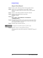
Testing for Isolation
Isolation needs to be measured only on adjacent ports. Two 50 Ω loads
are required for this test.
Step 1. Recall the adapter removal calibration stored previously in the internal
memory of the network analyzer
Step 2. Connect two (2) high-quality 50 Ω loads to both the Transmission and
Reflection ports on the test set.
Step 3. Turn the averaging on by pressing:
[AVG] > AVERAGING ON
Step 4. Connect the two cables that are attached to the network analyzer to
Port 1 and Port 2 of the test set. The exact order does not matter.
Step 5. Select "Reflection Port 1" on the network analyzer by pressing:
[SEQ] > TTL I/O > PARALLEL ALL OUT
Enter the decimal (D in Table 5-1 on page 5-6) value to select the port,
then press:
[x1]
Check the status LCD on the network analyzer for the port selected.
Step 6. Repeat the previous step (step 5), but select "Transmission Port 2" on
the network analyzer. Check the status LCD on the test set for the port
selected.
Step 7. On the network analyzer, press:
[MENU] > TRIGGER MENU > NUMBER OF GROUPS > [16] > [x1]
Wait until the analyzer is finished making the measurement, then
press:
[SCALE REF] > AUTO SCALE > [MARKER]
Step 8. On the analyzer, press:
MARKER FCTN > MKR SEARCH > TRACKING > ON > SEARCH > MAX
NOTE
Once the marker tacking is turned on, the user no longer needs to
repeat step 8
Step 9. Write the maximum value in the “Isolation Test Record”, Table 6-2 on
page 6-13, for the ports being measured.
Step 10. Repeat steps 5 through 9 for the next two adjacent ports, 2 and 3.
Repeat again for ports 3 and 4, and then for ports 4 and 5, and so on
until you have tested ports 15 and 16.
User’s and Service Guide
6-7
Servicing the Test Set
Performance Testing
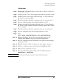
Testing for Return Loss
This test will check both the internal termination load of each port, as
well as the through match when the appropriate input port is
terminated with a 50 Ω load.
Set up the network analyzer using the following procedure.
Step 1. Set the number of points to 401 by pressing:
[MENU] > NUMBER OF POINTS > [401]
Step 2. Set the IF Bandwidth to 10 Hz by pressing:
[AVG] > IF BW > [10] > [x1]
Step 3. Perform a one-port S11 calibration at the end of the test port cable
connected to Port 1 of the analyzer.
Step 4. Make sure the calibration is active.
Step 5. Save the calibration into the internal memory of the network analyzer
by pressing:
[SAVE/RECALL] > SAVE STATE
Step 6. Verify the calibration is active and accurate using a short connected to
the test port cable.
Step 7. Locate the maximum and minimum values of the data trace by
pressing:
[MARKER]
and using the front panel knob. The displayed return loss should
measure ± 0.2 dB.
Step 8. Connect the cable (already connected to Port 1 of the analyzer) to Port 1
of the test set.
Step 9. Connect a high-quality 50 Ω load to the Transmission port of the test
set.
Step 10. Select the “all_term” command using the network analyzer by pressing:
[SEQ] > TTL I/O > PARALLEL ALL OUT > [34] > [x1]
This command will ensure that no conflicts will occur when selecting
the test set ports.
Step 11. Select "Transmission Port 1", on the network analyzer by pressing:
[SEQ] > TTL I/O > PARALLEL ALL OUT
Enter the decimal value (D in Table 5-1 on page 5-6) to select the port,
then press:
[x1]
Check the status LCD to verify the port selected.
Step 12. On the network analyzer, press:
[MENU] > TRIGGER MENU
Wait until the analyzer is finished taking a sweep, then press:
[SCALE REF] > AUTO SCALE > [MARKER]
6-8
User’s and Service Guide
Servicing the Test Set
Performance Testing
Step 13. Using the front panel knob, locate the maximum value of the data trace
for the 50 MHz to 2.0 GHz frequency range.
Step 14. Write the maximum value in the “Return Loss Test Record”, Table 6-3
on page 6-14, for the port being measured.
Step 15. Repeat the previous two steps for the other frequency ranges listed in
the “Return Loss Test Record”.
Step 16. Press:
[SEQ] > TTL I/O > PARALLEL OUT ALL > [34] > [x1]
Step 17. Using the front panel knob, locate the maximum value of the data trace
for the 50 MHz to 2.0 GHz frequency range.
Step 18. Write the maximum value in the “Return Loss Test Record”, Table 6-3
on page 6-14, for the port being measured.
Step 19. Repeat steps 10 through 18 for the remaining test ports (2 through 16).
Step 20. After all Transmission ports have been measured, move the
high-quality load attached on the Transmission port to the Reflection
port on the test set. Repeat steps 10 through step 19, but select the
Reflection ports instead of the Transmission ports.
This completes the performance testing instructions.
User’s and Service Guide
6-9
Servicing the Test Set
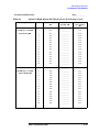
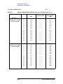
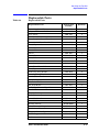
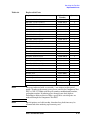
Performance Test Record
Performance Test Record
NOTE
This page and the following pages (Performance Test Record) are
designed to be duplicated and used as a template for either of the
Transmission or Reflection ports during each of the performance tests
(Insertion Loss, Return Loss, and Isolation). At the top of each page,
circle the appropriate input port, Transmission or Reflection, and write
in the test date.
Agilent 87050A Option H15 Test Record
Test Facility ____________________________
Report Number __________________________
________________________________________
Date ____________________________________
________________________________________
Date of Last System Calibration _____________
________________________________________
________________________________________
Tested by _______________________________
Customer _______________________________
Model __________________________________
Serial Number ___________________________
Ambient Temperature _________________° C
Relative Humidity _______________________%
Test Equipment
Used
Model Number
Trace Number
Cal Due Date
___________________
___________________
___________________
___________________
___________________
___________________
___________________
___________________
___________________
___________________
___________________
___________________
___________________
___________________
___________________
___________________
___________________
___________________
___________________
___________________
Special Notes:
__________________________________________________________________________________
__________________________________________________________________________________
__________________________________________________________________________________
__________________________________________________________________________________
__________________________________________________________________________________
6-10
User’s and Service Guide
Servicing the Test Set
Performance Test Record
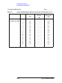
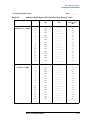
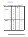
Transmission/Reflection
Table 6-1
Date___________
Agilent 87050A Option H15 Insertion Loss Test Record (1 of 2)
Test Description
Port
Specification
(dB)
Measured
Results
Measurement
Uncertainty (dB)
(dB)
Insertion Loss
1
≤1.5
__________
±0.3
300 kHz up to 1.3 GHz
2
≤1.5
__________
±0.3
3
≤1.5
__________
±0.3
4
≤1.5
__________
±0.3
5
≤1.5
__________
±0.3
6
≤1.5
__________
±0.3
7
≤1.5
__________
±0.3
8
≤1.5
__________
±0.3
9
≤1.5
__________
±0.3
10
≤1.5
__________
±0.3
11
≤1.5
__________
±0.3
12
≤1.5
__________
±0.3
13
≤1.5
__________
±0.3
14
≤1.5
__________
±0.3
15
≤1.5
__________
±0.3
16
≤1.5
__________
±0.3
Insertion Loss
1
≤1.75
__________
±0.3
1.3 GHz up to 3.0 GHz
2
≤1.75
__________
±0.3
3
≤1.75
__________
±0.3
4
≤1.75
__________
±0.3
5
≤1.75
__________
±0.3
6
≤1.75
__________
±0.3
7
≤1.75
__________
±0.3
8
≤1.75
__________
±0.3
9
≤1.75
__________
±0.3
10
≤1.75
__________
±0.3
11
≤1.75
__________
±0.3
12
≤1.75
__________
±0.3
13
≤1.75
__________
±0.3
14
≤1.75
__________
±0.3
15
≤1.75
__________
±0.3
16
≤1.75
__________
±0.3
User’s and Service Guide
6-11
Servicing the Test Set
Performance Test Record
Transmission/Reflection
Table 6-1
Date___________
Agilent 87050A Option H15 Insertion Loss Test Record (2 of 2)
Test Description
Port
Specification
(dB)
Measured
Results
(dB)
Measurement
Uncertainty
(dB)
Insertion Loss
1
≤2.5
__________
±0.3
3.0 GHz to 6.0 GHz
2
≤2.5
__________
±0.3
3
≤2.5
__________
±0.3
4
≤2.5
__________
±0.3
5
≤2.5
__________
±0.3
6
≤2.5
__________
±0.3
7
≤2.5
__________
±0.3
8
≤2.5
__________
±0.3
9
≤2.5
__________
±0.3
10
≤2.5
__________
±0.3
11
≤2.5
__________
±0.3
12
≤2.5
__________
±0.3
13
≤2.5
__________
±0.3
14
≤2.5
__________
±0.3
15
≤2.5
__________
±0.3
16
≤2.5
__________
±0.3
6-12
User’s and Service Guide
Servicing the Test Set
Performance Test Record
Transmission/Reflection
Table 6-2
Date___________
Agilent 87050A Option H15 Isolation Test Record (1 of 1)
Test Description
Port
Specification
Measured Results
(dB)
(dB)
Measurement
Uncertainty
(dB)
Isolation
1
≥100
__________
±5
300 kHz up to 3.0 GHz
2
≥100
__________
±5
3
≥100
__________
±5
4
≥100
__________
±5
5
≥100
__________
±5
6
≥100
__________
±5
7
≥100
__________
±5
8
≥100
__________
±5
9
≥100
__________
±5
10
≥100
__________
±5
11
≥100
__________
±5
12
≥100
__________
±5
13
≥100
__________
±5
14
≥100
__________
±5
15
≥100
__________
±5
16
≥100
__________
±5
Isolation
1
≥90
__________
±5
3.0 GHz to 6.0 GHz
2
≥90
__________
±5
3
≥90
__________
±5
4
≥90
__________
±5
5
≥90
__________
±5
6
≥90
__________
±5
7
≥90
__________
±5
8
≥90
__________
±5
9
≥90
__________
±5
10
≥90
__________
±5
11
≥90
__________
±5
12
≥90
__________
±5
13
≥90
__________
±5
14
≥90
__________
±5
15
≥90
__________
±5
16
≥90
__________
±5
User’s and Service Guide
6-13
Servicing the Test Set
Performance Test Record
Transmission/Reflection
Table 6-3
Date___________
Agilent 87050A Option H15 Return Loss Test Record (1 of 3)
Test Description
Port
Specification
(dB)
Measured
Results
Measurement
Uncertainty (dB)
(dB)
Return Loss
1
≥25
__________
±1.5
300 kHz up to 1.3 GHz
2
≥25
__________
±1.5
Switch Path ON
3
≥25
__________
±1.5
4
≥25
__________
±1.5
5
≥25
__________
±1.5
6
≥25
__________
±1.5
7
≥25
__________
±1.5
8
≥25
__________
±1.5
9
≥25
__________
±1.5
10
≥25
__________
±1.5
11
≥25
__________
±1.5
12
≥25
__________
±1.5
13
≥25
__________
±1.5
14
≥25
__________
±1.5
15
≥25
__________
±1.5
16
≥25
__________
±1.5
Return Loss
1
≥16
__________
±1.5
1.3 GHz up to 3.0 GHz
2
≥16
__________
±1.5
Switch Path ON
3
≥16
__________
±1.5
4
≥16
__________
±1.5
5
≥16
__________
±1.5
6
≥16
__________
±1.5
7
≥16
__________
±1.5
8
≥16
__________
±1.5
9
≥16
__________
±1.5
10
≥16
__________
±1.5
11
≥16
__________
±1.5
12
≥16
__________
±1.5
13
≥16
__________
±1.5
14
≥16
__________
±1.5
15
≥16
__________
±1.5
16
≥16
__________
±1.5
6-14
User’s and Service Guide
Servicing the Test Set
Performance Test Record
Transmission/Reflection
Table 6-3
Date___________
Agilent 87050A Option H15 Return Loss Test Record (2 of 3)
Test Description
Port
Specification
(dB)
Measured
Results (dB)
Measurement
Uncertainty
(dB)
Return Loss
1
≥12
__________
±0.6
3.0 GHz up to 6.0 GHz
2
≥12
__________
±0.6
Switch Path ON
3
≥12
__________
±0.6
4
≥12
__________
±0.6
5
≥12
__________
±0.6
6
≥12
__________
±0.6
7
≥12
__________
±0.6
8
≥12
__________
±0.6
9
≥12
__________
±0.6
10
≥12
__________
±0.6
11
≥12
__________
±0.6
12
≥12
__________
±0.6
13
≥12
__________
±0.6
14
≥12
__________
±0.6
15
≥12
__________
±0.6
16
≥12
__________
±0.6
Return Loss
1
≥26
__________
±1.5
300 kHz up to 1.3 GHz
2
≥26
__________
±1.5
Switch Path OFF
3
≥26
__________
±1.5
4
≥26
__________
±1.5
5
≥26
__________
±1.5
6
≥26
__________
±1.5
7
≥26
__________
±1.5
8
≥26
__________
±1.5
9
≥26
__________
±1.5
10
≥26
__________
±1.5
11
≥26
__________
±1.5
12
≥26
__________
±1.5
13
≥26
__________
±1.5
14
≥26
__________
±1.5
15
≥26
__________
±1.5
16
≥26
__________
±1.5
User’s and Service Guide
6-15
Servicing the Test Set
Performance Test Record
Transmission/Reflection
Table 6-3
Date___________
Agilent 87050A Option H15 Return Loss Test Record (3 of 3)
Test Description
Port
Specification
1
2
3
4
5
6
7
8
9
10
11
12
13
14
15
16
≥21
≥21
≥21
≥21
≥21
≥21
≥21
≥21
≥21
≥21
≥21
≥21
≥21
≥21
≥21
≥21
__________
__________
__________
__________
__________
__________
__________
__________
__________
__________
__________
__________
__________
__________
__________
__________
Measurement
Uncertainty
(dB)
±1.5
±1.5
±1.5
±1.5
±1.5
±1.5
±1.5
±1.5
±1.5
±1.5
±1.5
±1.5
±1.5
±1.5
±1.5
±1.5
1
2
3
4
5
6
7
8
9
10
11
12
13
14
15
16
≥15
≥15
≥15
≥15
≥15
≥15
≥15
≥15
≥15
≥15
≥15
≥15
≥15
≥15
≥15
≥15
__________
__________
__________
__________
__________
__________
__________
__________
__________
__________
__________
__________
__________
__________
__________
__________
±0.6
±0.6
±0.6
±0.6
±0.6
±0.6
±0.6
±0.6
±0.6
±0.6
±0.6
±0.6
±0.6
±0.6
±0.6
±0.6
(dB)
Return Loss
1.3 GHz up to 3.0 GHz
Switch Path OFF
Return Loss
3.0 GHz up to 6.0 GHz
Switch Path OFF
6-16
Measured
Results (dB)
User’s and Service Guide
Servicing the Test Set
Replaceable Parts
Replaceable Parts
Table 6-4
Replaceable Parts
Replacement Part
Agilent Part
Number
Quantity
Power Supply, 110 W
0950-2252
1
Adapter, 3.5 mm to APC 7
1250-1747
2
Feet, Spring
1460-1345
2
Termination, 50 Ω
1810-0118
6
Fuse, Daughter Control Board
2110-0158
1
Fuse, 3 A 250 V f, ac Line Module
2110-0780
2
Cover, Top
5002-1047
1
Cover, Bottom
5002-1088
1
Cover, Side
5002-3985
2
Shield
5002-4017
1
Frame, Rear
5021-5806
1
Strut, Side
5021-5837
4
Frame, Front
5022-1189
1
Foot
5041-9167
4
Trim, Front Frame Side
5041-9173
2
Trim, Top
5041-9176
1
Front Cap, Strap Handle
5041-9186
2
Rear Cap, Strap Handle
5041-9187
2
Standoff, Rear Panel
5041-9188
4
Handle, Strap
5063-9210
2
Kit, Front Handle
5063-9228
1
Kit, Rack Mount
5063-9235
1
Cable, Type-N (m) to Type-N (m)
8120-6995
1
Parallel Cable
8120-6818
1
IDSS Cable Strip
8120-8794
1
Cable Tie
9310-6480
1
Assembly, Switch
08711-60129
1
Rear Panel *
08720-00102
1
Bracket, Switch*
08720-00103
3
Wire Harness, Multiport*
08720-60191
1
Switch Assembly, 33314c-024
33314-60012
16
Adapter, APC-7 to Type-N (m)
85054-60001
1
Switch Support (12sw)*
87050-00020
1
Deck*
87050-00021
1
User’s and Service Guide
6-17
Servicing the Test Set
Replaceable Parts
Table 6-4
Replaceable Parts
Replacement Part
Agilent Part
Number
Quantity
RF Cable, J15-6 to J51-1, J16-6 to J57-1*
87050-20079
2
RF Cable, J14-5 to J51-1*
87050-20080
1
RF Cable, J15-6 to J53-1*
87050-20081
1
RF Cable, J15-5 to J62-1, J16-5 to J68-1*
87050-20082
2
RF Cable, J15-2 to J64-1, J16-2 to J70-1*
87050-20083
2
RF Cable, J14-3 to J66-1*
87050-20084
1
RF Cable, J15-4 to J63-1, J16-4 to J69-1*
87050-20085
2
RF Cable, J15-3 to J65-1, J16-3 to J71-1*
87050-20086
2
RF Cable, J14-4 to J67-1*
87050-20087
1
RF Cable, J10-6 to J51-2, J11-6 to J57-2*
87050-20091
2
RF Cable, J10-3 to J53-2*
87050-20092
1
RF Cable, J12-2 to J55-2*
87050-20093
1
RF Cable, J10-5 to J62-2, J11-5 to J68-2*
87050-20094
2
RF Cable, J12-6 to J64-2*
87050-20095
1
RF Cable, J12-3 to J66-2*
87050-20096
1
RF Cable, J10-4 to J63-2, J11-4 to J69-2*
87050-20097
2
RF Cable, J12-5 to J65-2*
87050-20098
1
RF Cable, J12-4 to J67-2*
87050-20099
1
RF Cable, J18-6 to J15-C*
87050-20100
1
RF Cable, J18-5 to J14-C*
87050-20101
1
RF Cable, J18-3 to J16-C*
87050-20102
1
RF Cable, J10-C to J19-6*
87050-20104
1
RF Cable, J12-C to J19-5*
87050-20105
1
RF Cable, J11-C to J19-3*
87050-20106
1
RF Cable, J63-C to Port 1*
87050-20158
1
RF Cable, J62-C to Port 2*
87050-20159
1
RF Cable, J51-C to Port 3*
87050-20160
1
RF Cable, J65-C to Port 4*
87050-20161
1
RF Cable, J64-C to Port 5*
87050-20162
1
RF Cable, J53-C to Port 6*
87050-20163
1
RF Cable, J67-C to Port 7*
87050-20164
1
RF Cable, J66-C to Port 8*
87050-20165
1
RF Cable, J55-C to Port 9*
87050-20166
1
RF Cable, J69-C to Port 10*
87050-20167
1
RF Cable, J68-C to Port 11*
87050-20168
1
RF Cable, J57-C to Port 12*
87050-20169
1
RF Cable, J71-C to Port 13*
87050-20170
1
6-18
User’s and Service Guide
Servicing the Test Set
Replaceable Parts
Table 6-4
Replaceable Parts
Replacement Part
Agilent Part
Number
Quantity
RF Cable, J70-C to Port 14*
87050-20171
1
RF Cable, J73-C to Port 15*
87050-20172
1
RF Cable, J72-C to Port 16*
87050-20173
1
RF Cable, J10-2 to J70-2*
87050-20174
1
RF Cable, J12-1 to J71-2*
87050-20175
1
RF Cable, J14-1 to J72-1*
87050-20176
1
RF Cable, J15-1 to J73-1*
87050-20177
1
RF Cable, J11-3 to J72-2*
87050-20178
1
RF Cable, J10-1 to J73-2*
87050-20179
1
RF Cable, J18-C to Reflection*
87050-20180
1
RF Cable, J19-C to Trans.*
87050-20181
1
Wire Harness, 04c, 0.3m, 13f-06f
87050-60021
1
Wire Harness, 04c, 0.13m, 04f-04f
87050-60022
1
Wire Harness, 40c, 0.09m, 40f-40f
87050-60023
3
Fan Assembly 5 cfm
87050-60027
1
Daughter Control Board
87050-60050
1
Ribbon Cable 16c 16f/16f
87050-60055
8
Wire Harness, Multiport*
87050-60070
1
Front Panel Subassembly*
87050-60169
1
Controller Mother Board *
87050-60170
1
Display Subassembly *
87050-60193
1
User's and Service Guide*
87050-90029
1
Bracket, Fan
87075-00005
1
Switch, 1p4t 26.5
87104-60001
2
Switch, 1p6t 26.5
87106-60009
6
Cable Assembly, AC Line
87130-60007
1
See Figure 3-3
1
Power Cord
NOTE
The parts indicated with an asterisk (*) are unique to this special
option. To order replacement parts, please contact the Component Test
PGU at (707) 577-6802 with the part number, module/model number,
and option number. If ordering parts through your local Agilent
Technologies Sales or Service Office, specify that asterisk parts are
ordered through the Component Test PGU.
NOTE
Special options are built to order, therefore long lead times may be
encountered when ordering replacement parts.
User’s and Service Guide
6-19
Servicing the Test Set
Troubleshooting the Test Set
Troubleshooting the Test Set
This section contains information on troubleshooting the test set to the
assembly level only. By following these procedures you should be able to
determine whether the power supply, front panel, or main switch board
needs replacing. A block diagram is included at the end of this section
as an aid in troubleshooting.
Theory of operation information can be found in the next section of this
manual.
General Troubleshooting Notes
WARNING
Always turn the instrument power off before removing or
installing an assembly.
CAUTION
If you need to disassemble the instrument, be sure to work at an
antistatic workstation and use a grounded wrist strap to prevent
damage from electrostatic discharge (ESD). Refer to Figure 1-3 on
page 1-7.
Troubleshooting Power Supply Problems
Turn the instrument on. Check the condition of the LCD on the front
panel:
Step 1. If the LCD is off, check the main fuse located in the power supply filter
at the rear of the instrument.
Step 2. If the LCD is off, there is still a possibility that the power supply is not
supplying the necessary +24 V, +12 V, and +5 V to the main board.
Check the cable connection between the main board and the front panel
board.
Step 3. Finally, disconnect the DC power cable from the power supply to the
main switch board and measure the voltages. They should be +24 V,
+12 V, and +5 V. If not, replace the power supply.
6-20
User’s and Service Guide
Servicing the Test Set
Troubleshooting the Test Set
Troubleshooting the Front Panel Board
Turn the instrument power on and do the following:
Step 1. Check the condition of each of the switching paths by issuing
commands to switch each of the paths to either the Transmission or
Reflection path. Ensure that the LCD indicates the appropriate path.
Step 2. If the LCD indicates a wrong path, the problem can lie with either the
front panel board or the main switch board. Measure the RF path to
determine where the problem is.
Step 3. If the LCD does not display the proper path, check to see if the RF path
has indeed been switched. If the problem lies with the front panel
board, replace the board.
Troubleshooting the Controller and Switch Driver
Boards
Turn the instrument power on and do the following:
Step 1. Check the condition of each of the switching paths by issuing
commands to switch each of the paths to either the Transmission or
Reflection path.
Step 2. Check the RF paths for connection. If an RF path is not connected to the
necessary port or terminated in 50 Ω, replace the controller and switch
driver board.
A block diagram for the Agilent 87050A Option H15 is provided on the
following page. Refer to Figure 6-1 on page 6-22.
User’s and Service Guide
6-21
6-22
2
3
4
C
5
5
6
3
2
Reflection
J70-2
J63-2
J51-2
J62-2
J74-2
J53-2
1
6
J18
2
3
4
C
5
6
NC
1
J11
NC
2
4
C
5
6
J69-2
J57-2
J72-2
J68-2
3
A2
Display LCD
Board
2
3
1
1
J63
2
1
2
J62
2
1
3
J51
2
1
4
J65
2
1
J64
5
2
1
6
J53
2
1
7
J67
2
1
2
1
9
J55
2
1
2
10
J69
Test Ports
8
J66
4
C
5
6
6
J19
5
2
2
3
4
C
5
50==Ω
1
2
11
J68
1
2
12
J57
1
2
13
J71
6
J55-1
J67-1
NC
J72-1
J66-1
J53-1
1
J14
3
2
14
J70
1
2
15
J74
1
2
16
J72
1
J11-3
J10-2
J11-6
J10-1
J12-1
J11-5
J14-1
J16-2
J16-6
J15-1
J16-3
J16-5
J64-1
J63-1
J51-1
J62-1
J74-1
J65-1
1
J15
J11-4
J12-3
J10-3
J12-5
J12-2
J12-4
J12-6
J10-6
J10-4
J10-5
J16-4
J14-3
J14-5
J15-3
J14-2
J14-4
J15-2
J15-6
J15-5
J15-4
J55-2
J67-2
J64-2
J71-2
J66-2
J65-2
1
J12
50==Ω
A3
Controller Interface
Mother Board
NC
1
J16
3
4
C
5
6
J70-1
J69-1
J57-1
J71-1
J68-1
2
Transmission
Figure 6-1
J10
A1
Power
Supply
A3
Driver
Daughter Board
Servicing the Test Set
Troubleshooting the Test Set
Block Diagram of the Agilent 87050A Option H15
User’s and Service Guide
Servicing the Test Set
Theory of Operation
Theory of Operation
The theory of operation begins with a general description of the
Agilent 87050A Option H15 multiport test set. This is followed by more
detailed operating theory. The operation of each group is described
briefly, to the assembly level only. Detailed component level circuit
theory is not provided.
System Theory
The test set consists of three main components:
• power supply
• front panel display
• controller interface mother board
The purpose of the power supply is to provide power to both the front
panel display and the main switch board. The front panel display serves
to indicate the switching paths to the user. Finally, the controller
interface mother board does the actual switching between the different
ports.
A1 Power Supply Theory
The switching power supply provides regulated dc voltages to power all
assemblies in the test set. A dc cable provides power to the main switch
board. A connector from the main switch board to the front panel
display provides dc power and control signals to the front panel. The
power supply provides the following voltages: +24 V, +12 V, and +5 V.
A2 Front Panel Display Theory
The front panel display consists of an LCD. The LCD is divided into two
sections, Reflection and Transmission. The first section indicates which
of the ten ports is connected to the Reflection port. The second section
indicates which of the sixteen ports is connected to the Transmission
port. Control signals and dc power are provided by a cable connected to
the main switch board.
User’s and Service Guide
6-23
Servicing the Test Set
Theory of Operation
A3 Controller Board (Mother Board) and Switch Driver Board
(Daughter Board) Theory
Refer to the block diagram, Figure 6-1 on page 6-22, for the following
discussion.
The mother and daughter boards provide the bias for the switching
paths for the various ports to the Transmission and Reflection ports.
The front panel display contains an LCD that indicates the switched
ports. A particular test port (1 through 16) can be in one of three states.
The three states are as follows:
• Switched to the forward path
• Switched to the reverse path
• Terminated in 50 Ω
When a port is not connected, it is automatically terminated in 50 Ω.
The test set consists of sixteen (16) 1 by 2 switches, six (6) 1 by 6
switches, and two (2) 1 by 4 switches. The 1 by 2 switches divide each of
the input ports (1 through 16) into two separate paths, the
Transmission path or the Reflection path.
Each path, Transmission or Reflection, connects to a bank of three (3)
1 by 6 switches (for a total of six (6) 1 by 6 switches). The 1 by 6
switches connect to a bank of two (2) 1 by 4 switches. Each bank of 1 by
6 switches connects to a single 1 by 4 switch where it connects to either
the Transmission or Reflection port.
All switches are mechanical, and are biased according to the necessary
switching path. A user interface through the GPIB and parallel ports
converts the necessary input signals from the user to the necessary
signals controlling the switching paths.
6-24
User’s and Service Guide
7
Safety and Regulatory Information
User’s and Service Guide
7-1
Safety and Regulatory Information
Safety and Regulatory Information
Safety and Regulatory Information
Introduction
Review this product and related documentation to familiarize yourself
with safety markings and instructions before you operate the
instrument. This product has been designed and tested in accordance
with international standards.
Cleaning Instructions
Clean the instrument cabinet using a damp cloth only.
Shipping Instructions
Always transport or ship the instrument using the original packaging if
possible. If not, comparable packaging must be used.
Before Applying Power
Verify that the product is configured to match the available main power
source as described in the input power configuration instructions in this
manual. If this product is to be powered by autotransformer, make sure
the common terminal is connected to the neutral (grounded) side of the
ac power supply.
7-2
User’s and Service Guide
Safety and Regulatory Information
Safety and Regulatory Information
Safety Information
Warnings
WARNING
The WARNING notice denotes a hazard. It calls attention to a
procedure, practice, or the like, which if not correctly performed or
adhered to, could result in personal injury. Do not proceed beyond a
WARNING notice until the indicated conditions are fully understood
and met.
Warnings applicable to this instrument are:
WARNING
No operator serviceable parts inside. Refer servicing to qualified
personnel. To prevent electrical shock, do not remove covers.
WARNING
If this instrument is not used as specified, the protection provided by
the equipment could be impaired. This instrument must be used in a
normal condition (in which all means for protection are intact) only.
WARNING
For continued protection against fire hazard replace line fuse only
with same type and rating:
• United States—F 3A/250V, Part Number 2110-0780
• Europe—F 3.15A/250V, Part Number 2110-0655
The use of other fuses or material is prohibited.
WARNING
This is a Safety Class I product (provided with a protective earthing
ground incorporated in the power cord). The mains plug shall be
inserted only into a socket outlet provided with a protective earth
contact. Any interruption of the protective conductor, inside or
outside the instrument, is likely to make the instrument dangerous.
Intentional interruption is prohibited.
WARNING
The power cord is connected to internal capacitors that may retain
dangerous electrical charges for 5 seconds after disconnecting the
plug from its power supply.
WARNING
These servicing instructions are for use by qualified personnel only.
To avoid electrical shock, do not perform any servicing unless you are
qualified to do so.
WARNING
The opening of covers or removal of parts is likely to expose
dangerous voltages. Disconnect the instrument from all voltage
sources while it is being opened.
WARNING
This product is designed for use in Installation Category II and
Pollution Degree 2 per IEC 1010 and 664 respectively.
User’s and Service Guide
7-3
Safety and Regulatory Information
Safety and Regulatory Information
Cautions
CAUTION
The CAUTION notice denotes a hazard. It calls attention to an
operating procedure, practice, or the like, which if not correctly
performed or adhered to, could result in damage to the product or loss of
important data. Do not proceed beyond a CAUTION notice until the
indicated conditions are fully understood and met.
Cautions applicable to this instrument are:
CAUTION
Always use the three-prong ac power cord supplied with this
instrument. Failure to ensure adequate earth grounding (by not using
this cord) can cause instrument damage.
CAUTION
This instrument has autoranging line voltage input; be sure the supply
voltage is within the specified range.
CAUTION
Ventilation Requirements: When installing the instrument in a cabinet,
the convection into and out of the instrument must not be restricted.
The ambient temperature (outside the cabinet) must be less than the
maximum operating temperature of the instrument by 4°=C for every
100 watts dissipated in the cabinet. If the total power dissipated in the
cabinet is greater than 800 watts, forced convection must be used.
7-4
User’s and Service Guide
Safety and Regulatory Information
Safety and Regulatory Information
Instrument
Markings
!
When you see this symbol on your instrument, you should
refer to the instrument’s instruction manual for important
information.
This symbol indicates hazardous voltages.
The laser radiation symbol is marked on products that have
a laser output.
This symbol indicates that the instrument requires
alternating current (ac) input.
The CE mark is a registered trademark of the European
Community. If it is accompanied by a year, it indicates the
year the design was proven.
The CSA mark is a registered trademark of the Canadian
Standards Association.
ISM1-A
This text indicates that the instrument is an Industrial
Scientific and Medical Group 1 Class A product (CISPER
11, Clause 4).
This symbol indicates that the power line switch is ON.
This symbol indicates that the power line switch is OFF or
in STANDBY position.
This symbol indicates the product meets the Australian
Standards.
Safety
Earth
Ground
This is a Safety Class I product (provided with a protective earthing
terminal). An uninterruptible safety earth ground must be provided
from the main power source to the product input wiring terminals,
power cord, or supplied power cord set. Whenever it is likely that the
protection has been impaired, the product must be made inoperative
and secured against any unintended operation.
User’s and Service Guide
7-5
Safety and Regulatory Information
Agilent Technologies Sales and Service Offices
Agilent Technologies Sales and Service Offices
UNITED STATES
Instrument Support Center
Agilent Technologies
(800) 403-0801
EUROPEAN FIELD OPERATIONS
Headquarters
Agilent Technologies S.A.
150, Route du Nant-d’Avril
1217 Meyrin 2/ Geneva
Switzerland
(41 22) 780.8111
France
Agilent Technologies France
1 Avenue Du Canada
Zone D’Activite De
Courtaboeuf
F-91947 Les Ulis Cedex
France
(33 1) 69 82 60 60
Germany
Agilent Technologies GmbH
Agilent Technologies Strasse
61352 Bad Homburg v.d.H
Germany
(49 6172) 16-0
Great Britain
Agilent Technologies Ltd.
Eskdale Road, Winnersh
Triangle Wokingham, Berkshire
RG41 5DZ England
(44 118) 9696622
INTERCON FIELD OPERATIONS
Headquarters
Agilent Technologies
3495 Deer Creek Rd.
Palo Alto, CA 94304-1316
USA
(415) 857-5027
Australia
Agilent Technologies Australia
Ltd.
31-41 Joseph Street
Blackburn, Victoria 3130
(61 3) 895-2895
Canada
Agilent Technologies (Canada)
Ltd.
17500 South Service Road
Trans-Canada Highway
Kirkland, Quebec H9J 2X8
Canada
(514) 697-4232
Japan
Agilent Technologies Japan, Ltd.
Measurement Assistance Center
9-1, Takakura-Cho, Hachioji-Shi,
Tokyo 192-8510, Japan
TEL (81) -426-56-7832
FAX (81) -426-56-7840
Singapore
Agilent Technologies
Singapore (Pte.) Ltd.
150 Beach Road
#29-00 Gateway West
Singapore 0718
(65) 291-9088
Taiwan
Agilent Technologies Taiwan
8th Floor, H-P Building
337 Fu Hsing North Road
Taipei, Taiwan
(886 2) 712-0404
China
China Agilent Technologies
38 Bei San Huan X1 Road
Shuang Yu Shu
Hai Dian District
Beijing, China
(86 1) 256-6888
7-6
User’s and Service Guide