1
Sun StorageTek™ SAS RAID HBA
Installation Guide
Eight-Port, External HBA
Model SG-XPCIESAS-R-EXT-Z
Sun Microsystems, Inc.
www.sun.com
Part No. 820-1260-15
November 2009, Revision A
Submit comments about this document by clicking the Feedback[+] link at: http://docs.sun.com
Copyright © 2009 Sun Microsystems, Inc., 4150 Network Circle, Santa Clara, California 95054, U.S.A. All rights reserved.
U.S. Government Rights - Commercial software. Government users are subject to the Sun Microsystems, Inc. standard license agreement and
applicable provisions of the FAR and its supplements.
Use is subject to license terms.
This distribution may include materials developed by third parties.
Parts of the product may be derived from Berkeley BSD systems, licensed from the University of California. UNIX is a registered trademark in
the U.S. and in other countries, exclusively licensed through X/Open Company, Ltd.
Sun, Sun Microsystems, the Sun logo, Netra, Solaris, Sun Ray, Sun StorEdge, Sun StorageTek, Sun Blade, SunVTS, and SunSolve are trademarks
or registered trademarks of Sun Microsystems, Inc., and its subsidiaries, in the U.S. and other countries.
All SPARC trademarks are used under license and are trademarks or registered trademarks of SPARC International, Inc. in the U.S. and other
countries. Products bearing SPARC trademarks are based upon architecture developed by Sun Microsystems, Inc.
This product is covered and controlled by U.S. Export Control laws and may be subject to the export or import laws in other countries. Nuclear,
missile, chemical biological weapons or nuclear maritime end uses or end users, whether direct or indirect, are strictly prohibited. Export or
reexport to countries subject to U.S. embargo or to entities identified on U.S. export exclusion lists, including, but not limited to, the denied
persons and specially designated nationals lists is strictly prohibited.
DOCUMENTATION IS PROVIDED "AS IS" AND ALL EXPRESS OR IMPLIED CONDITIONS, REPRESENTATIONS AND WARRANTIES,
INCLUDING ANY IMPLIED WARRANTY OF MERCHANTABILITY, FITNESS FOR A PARTICULAR PURPOSE OR NON-INFRINGEMENT,
ARE DISCLAIMED, EXCEPT TO THE EXTENT THAT SUCH DISCLAIMERS ARE HELD TO BE LEGALLY INVALID.
Copyright © 2009 Sun Microsystems, Inc., 4150 Network Circle, Santa Clara, California 95054, Etats-Unis. Tous droits réservés.
L'utilisation est soumise aux termes de la Licence.
Cette distribution peut comprendre des composants développés par des tierces parties.
Des parties de ce produit pourront être dérivées des systèmes Berkeley BSD licenciés par l'Université de Californie. UNIX est une marque
déposée aux Etats-Unis et dans d'autres pays et licenciée exclusivement par X/Open Company, Ltd.
Sun, Sun Microsystems, le logo Sun, Netra, Solaris, Sun Ray, Sun StorEdge, Sun StorageTek, Sun Blade, SunVTS, et SunSolve sont des marques
de fabrique ou des marques déposées de Sun Microsystems, Inc., et ses filiales, aux Etats-Unis et dans d'autres pays.
Toutes les marques SPARC sont utilisées sous licence et sont des marques de fabrique ou des marques déposées de SPARC International, Inc.
aux Etats-Unis et dans d'autres pays. Les produits portant les marques SPARC sont basés sur une architecture développée par Sun
Microsystems, Inc.
Ce produit est soumis à la législation américaine en matière de contrôle des exportations et peut être soumis à la règlementation en vigueur
dans d'autres pays dans le domaine des exportations et importations. Les utilisations, ou utilisateurs finaux, pour des armes nucléaires,des
missiles, des armes biologiques et chimiques ou du nucléaire maritime, directement ou indirectement, sont strictement interdites. Les
exportations ou réexportations vers les pays sous embargo américain, ou vers des entités figurant sur les listes d'exclusion d'exportation
américaines, y compris, mais de manière non exhaustive, la liste de personnes qui font objet d'un ordre de ne pas participer, d'une façon directe
ou indirecte, aux exportations des produits ou des services qui sont régis par la législation américaine en matière de contrôle des exportations et
la liste de ressortissants spécifiquement désignés, sont rigoureusement interdites.
LA DOCUMENTATION EST FOURNIE "EN L’ÉTAT" ET TOUTES AUTRES CONDITIONS, DECLARATIONS ET GARANTIES EXPRESSES
OU TACITES SONT FORMELLEMENT EXCLUES, DANS LA MESURE AUTORISEE PAR LA LOI APPLICABLE, Y COMPRIS NOTAMMENT
TOUTE GARANTIE IMPLICITE RELATIVE A LA QUALITE MARCHANDE, A L’APTITUDE A UNE UTILISATION PARTICULIERE OU A
L’ABSENCE DE CONTREFAÇON.
Please
Recycle
Contents
Preface
1.
xv
HBA Overview
Kit Contents
HBA Features
1
1
2
Array-Level Features
2
Advanced Data Protection Suite
Component Layout
3
3
Operating System and Technology Requirements
System Interoperability
6
Host Platform Support
Server Support
6
7
Storage System Support
Software Support
2.
7
8
Hardware Installation and Removal
9
Observing ESD and Handling Precautions
Preparing for Hardware Installation
▼
5
9
10
To Prepare for Hardware Installation
Installation Task Map
10
11
iii
Installing the Battery Backup Module
▼
12
To Install the Battery Backup Module
12
Verifying the Current Devices on a SPARC System
▼
To Verify the Current Devices
Installing the HBA
▼
14
15
To Install the HBA
15
Connecting Disk Drive Enclosures
▼
16
17
▼
To Test the HBA Installation on a SPARC System
▼
To Test the HBA Installation on an x64 System
Next Steps
17
20
22
Removing the Hardware
22
▼
To Prepare the HBA for Removal
▼
To Remove the HBA
22
23
Installing the Driver on an Existing Operating System
Preparing to Install the HBA Driver
25
25
Installing the Driver on an Existing OS
26
▼
To Install the Driver on the Windows OS
▼
To Install the Driver on the Red Hat or SUSE Linux OS
▼
To Install the Driver on the Solaris OS on an x64 System
▼
To Install the Driver on the Solaris OS on a SPARC System
▼
To Install the Driver on VMware Technology
Next Steps
4.
16
To Connect Disk Drive Enclosures
Testing the HBA Installation
3.
14
26
28
28
Known Issues
29
Ship Kit Issues
29
Some or All CDs Are Not Included in the HBA Ship Kit
iv
26
29
Sun StorageTek SAS RAID HBA Installation Guide Eight-Port, External HBA • November 2009
27
27
BIOS Utility Issues
30
Creating an Array With the BIOS Utility Changes the BIOS Boot Order
Hot-Plug Functionality Does Not Work in the BIOS Utility
Performance Issues
30
30
30
ZFS Forces a Flush of the NVRAM on the HBA When Completing
Synchronous Writes, Which Impacts Performance 31
The System Freezes When a Sun Storage 32GB SLC SATA Solid State Drive
(SSD) Is Configured In the HBA 32
A Space Usage Error Message Is Displayed When Trying to Expand an
Existing Volume 32
Cannot Access the HBA From the GUI Nor Access a LUN From the Host
JBOD Issues
33
33
Difficulty With Detecting Disks in a JBOD
33
During System Boot Time, JBOD Affiliations Cause HBA Inoperability and
System Panic 34
After Upgrading Firmware on a JBOD, the JBOD Is No Longer Detected by the
GUI 34
The Solaris System Panics After Attaching a JBOD to the HBA
A.
Configuration Rules
Target Devices
Cabling
B.
34
37
37
38
HBA Specifications
39
Physical Dimensions
39
Environmental Specifications
DC Power Requirements
Current Requirements
40
40
Performance Specifications
Connector Pin Definitions
SAS Pin-Out
40
40
41
41
Contents
v
SATA Pin-Out
C.
42
Using the BIOS RAID Configuration Utility
45
Introduction to the BIOS RAID Configuration Utility
46
Understanding Hot-Plug Limitations and Conditions Within the BIOS RAID
Configuration Utility 46
Hot-Unplug Removal Conditions
Hot-Plug Addition Conditions
46
47
Hot-Unplug and Plug Replacement/Reinsertion Conditions
Running the BIOS RAID Configuration Utility
48
▼
To Start the BIOS RAID Configuration Utility
▼
To Navigate the BIOS RAID Configuration Utility
Using the ACU to Create and Manage Arrays
48
48
49
▼
To Start Using the ACU
▼
To Create a New Array With the ACU
▼
To Manage Existing Arrays With the ACU
51
▼
To Make an Array Bootable With the ACU
51
▼
To Initialize Disk Drives With the ACU
▼
To Rescan Disk Drives With the ACU
▼
To Perform a Secure Erase on Disk Drives With the ACU
▼
To Stop a Secure Erase in Progress With the ACU
50
50
52
52
Using the -Select Utility to Modify HBA Settings
52
53
53
▼
To Start Using a -Select Utility
▼
To Apply Changes and Exit The -Select Utility
▼
To Modify General HBA Settings With a -Select Utility
▼
To Modify SAS-Specific HBA Settings With a -Select Utility
53
53
Formatting and Verifying Disk Drives With the Disk Utilities
vi
47
54
56
▼
To Format or Verify a Disk Drive With the Disk Utilities
▼
To Locate a Disk Drive With the Disk Utilities
56
Sun StorageTek SAS RAID HBA Installation Guide Eight-Port, External HBA • November 2009
56
55
▼
To Identify a Disk Drive With the Disk Utilities
Viewing the BIOS-Based Event Log
▼
D.
59
To View the BIOS-Based Event Log
Troubleshooting
59
61
Troubleshooting Checklist
Silencing the Alarm
61
62
Recovering From a Disk Drive Failure
62
Failed Disk Drive Protected by a Hot-Spare
▼
To Recover From the Failure
62
62
Failed Disk Drive Not Protected by a Hot-Spare
Failure in Multiple Arrays Simultaneously
Disk Drive Failure in a RAID 0 Array
Multiple Failures in the Same Array
E.
Best Practices
58
63
63
63
64
65
Best Practices For Placing a New HBA in a System Running the Solaris OS
Best Practices For Switching Cables and Making New Connections
Switching a Cable From One Port To the Other Port
Pulling a Cable and Reconnecting It To the Same Port
Connecting a JBOD With SATA Disks
66
66
67
67
Best Practices For Cabling to Disk Enclosures
67
Best Practices For Testing Hard Drive Failure Conditions
67
Best Practices For Deleting Logical Volumes Without Deleting Partitions
Best Practices For Testing Physical Drive Failures
68
68
Best Practices For Rescanning or Discovering Drives
69
Best Practices For Controlling the Boot Order of Logical Drives
69
Best Practices For Selecting Members of RAID Logical Devices
70
Best Practices For Replacing an HBA
65
70
Contents
vii
Replacing an HBA On a SPARC System
Replacing an HBA On an x64 System
F.
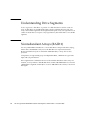
Selecting the Best RAID Level
73
Understanding Drive Segments
74
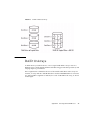
Nonredundant Arrays (RAID 0)
74
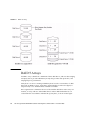
RAID 1 Arrays
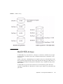
RAID 10 Arrays
76
77
78
RAID 5EE Arrays
RAID 50 Arrays
RAID 6 Arrays
79
80
82
RAID 60 Arrays
83
Selecting the Best RAID Level
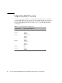
Migrating RAID Levels
G.
83
84
Introduction to Serial Attached SCSI
Terminology Used in This Appendix
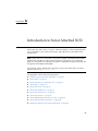
About SAS
86
87
87
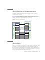
About SAS Ports
88
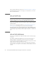
About SAS Addresses
About SAS Connectors
About SAS Cables
88
89
89
About Identifying Disk Drives in SAS
About SAS Connection Options
Direct-Attach Connections
viii
85
86
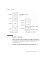
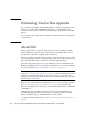
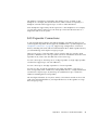
About SAS Device Communication
About Phys
71
75
RAID 1 Enhanced Arrays
RAID 5 Arrays
71
89
90
90
Sun StorageTek SAS RAID HBA Installation Guide Eight-Port, External HBA • November 2009
Backplane Connections
90
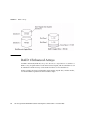
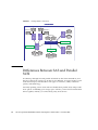
SAS Expander Connections
91
Differences Between SAS and Parallel SCSI
H.
92
Declaration of Conformity, Safety, and Regulatory Statements
Declaration of Conformity
97
Safety Agency Compliance Statements
Regulatory Compliance Statements
Index
95
99
111
113
Contents
ix
x
Sun StorageTek SAS RAID HBA Installation Guide Eight-Port, External HBA • November 2009
Figures
FIGURE 1-1
Sun StorageTek SAS RAID External HBA Component Layout
4
FIGURE 2-1
External SAS Cable (SFF-8088 Connector) Used to Connect to an External Hard Disk Drive
Enclosure 11
FIGURE 2-2
Installing the BBU
FIGURE 2-3
Remove Slot Cover from Expansion Slot
FIGURE 2-4
Installing the Sun StorageTek SAS RAID External HBA
FIGURE F-1
RAID 0 Array
75
FIGURE F-2
RAID 1 Array
76
FIGURE F-3
RAID 1 Enhanced Array
FIGURE F-4
RAID 10 Array 78
FIGURE F-5
RAID 5 Array
FIGURE F-6
RAID 5EE Array
FIGURE F-7
RAID 50 Array 81
FIGURE F-8
RAID 6 Array
FIGURE G-1
SAS Device Communication
FIGURE G-2
SAS Expander Connections 92
13
15
16
77
79
80
82
87
xi
xii
Sun StorageTek SAS RAID HBA Installation Guide Eight-Port, External HBA • November 2009
Tables
TABLE 1-1
Sun StorageTek SAS RAID External HBA Features
TABLE 1-2
Supported Operating System Versions
TABLE 1-1
Supported Servers
TABLE 1-3
Software Support 8
TABLE B-1
Environmental Specifications
TABLE B-2
SAS Pin-Out
TABLE B-3
SATA Data Pin-Out
TABLE B-4
SATA Power Pin-out
TABLE C-1
General HBA Settings
TABLE C-2
SAS HBA Settings 55
TABLE C-3
Information Provided by Disk Utilities
TABLE F-1
Selecting the Best RAID Level
TABLE F-2
Supported RAID Level Migrations
TABLE G-1
Differences between Parallel SCSI and SAS
4
5
7
40
41
42
43
54
58
83
84
93
xiii
xiv
Sun StorageTek SAS RAID HBA Installation Guide Eight-Port, External HBA • November 2009
Preface
This installation guide explains how to install the eight-port, external Sun
StorageTekTM SAS RAID HBA (referred to in this document as Sun StorageTek SAS
RAID External HBA). It also describes how to install the driver, and provides a basic
overview of Serial Attached SCSI (SAS) and Redundant Array of Independent Disk
(RAID) technology.
Before You Read This Document
Familiarize yourself with computer hardware, data storage, RAID technology, and
the input/output (I/O) technology—SAS, or Serial ATA (SATA)—used by the HBA.
Also, familiarize yourself with Direct-Attached Storage (DAS) or Network-Attached
Storage (NAS)—whichever is appropriate for your storage space—and Storage Area
Network (SAN) concepts and technology.
Using UNIX Commands
This document might not contain information about basic UNIX® commands and
procedures such as shutting down the system, booting the system, and configuring
devices. Refer to the following for this information:
■
Software documentation that you received with your system
■
Solaris™ Operating System documentation, which is at:
http://docs.sun.com
xv
Related Documentation
The following table lists the documentation for this product. The online
documentation is available at:
http://docs.sun.com/app/docs/prod/stortek.raid.hba#hic
Application
Title
Part Number
Format
Location
Commandline interface
Uniform Command-Line
Interface User’s Guide
820-2145-nn
PDF
HTML
CD, Online
RAID
Management
Sun StorageTek RAID
Manager Software User’s
Guide
820-1177-nn
PDF
HTML
CD, Online
RAID
Management
Sun StorageTek RAID
Manager Software Release
Notes
820-2755-nn
PDF
HTML
CD, Online
Documentation, Drivers, Support, and
Training
xvi
Sun Function
URL
Documentation
http://www.sun.com/documentation/
Drivers (not including
Solaris)
http://support.intel.com/support/go/sunraid.htm
Support
http://www.sun.com/support/
Training
http://www.sun.com/training/
Sun StorageTek SAS RAID HBA Installation Guide Eight-Port, External HBA • November 2009
Third-Party Web Sites
Sun is not responsible for the availability of third-party web sites mentioned in this
document. Sun does not endorse and is not responsible or liable for any content,
advertising, products, or other materials that are available on or through such sites or
resources. Sun will not be responsible or liable for any actual or alleged damage or
loss caused by or in connection with the use of or reliance on any such content,
goods, or services that are available on or through such sites or resources.
Sun Welcomes Your Comments
Sun is interested in improving its documentation and welcomes your comments and
suggestions. You can submit your comments by going to:
http://www.sun.com/hwdocs/feedback
Please include the title and part number of your document with your feedback:
Sun StorageTek™ SAS RAID HBA Installation Guide Eight-Port, External HBA, part
number 820-1260-15
Preface
xvii
xviii
Sun StorageTek SAS RAID HBA Installation Guide Eight-Port, External HBA • November 2009
CHAPTER
1
HBA Overview
This chapter provides an overview of the eight-port, external Sun StorageTek SAS
RAID HBA (referred to in this document as Sun StorageTek SAS RAID External
HBA), which uses Adaptec® technology. The chapter describes the various operating
systems, host platforms, and infrastructure configurations that support the HBA.
The chapter contains the following sections:
■
“Kit Contents” on page 1
■
“HBA Features” on page 2
■
“Operating System and Technology Requirements” on page 5
■
“System Interoperability” on page 6
Kit Contents
■
Sun StorageTek SAS RAID External HBA
■
Full-height bracket
■
Battery backup (BBU) module and installation hardware
■
Sun StorageTek RAID Driver CD
■
Sun StorageTek RAID Manager CD (which contains the HBA documentation)
■
Live CD
Note – If a CD listed in this section is not included in the ship kit, you can obtain
the contents of the CD at:
http://support.intel.com/support/go/sunraid.htm
1
HBA Features
The external Sun StorageTek SAS RAID HBA (SG-XPCIESAS-R-EXT-Z) has the
following features:
Note – These features are supported by some operating systems but not others. For
more information, refer to the Sun StorageTek RAID Manager Software User’s Guide or
online Help.
■
Flash ROM to update the HBA firmware and BIOS using the BIOS Configuration
Utility or the Sun StorageTek RAID Manager graphical user interface (GUI) (see
the Sun StorageTek RAID Manager Software User’s Guide)
■
Disk drive hot-swapping (See the HDD hot-plug guidelines in “Understanding
Hot-Plug Limitations and Conditions Within the BIOS RAID Configuration
Utility” on page 46)
■
Event logging and broadcasting including email and SNMP messages
■
The Sun StorageTek RAID Manager GUI, a BIOS-based utility, and a commandline interface for creating and managing RAID arrays
■
Support for disk drive enclosures with SES2 enclosure management hardware
■
A battery backup module
Array-Level Features
Note – These features are supported by some operating systems but not others. For
more information, refer to the Sun StorageTek RAID Manager Software User’s Guide or
online Help.
2
■
Support for RAID levels 0, 1, 1E, 10, 5, 5EE, 50, 6, 60, simple volume, spanned
volume, and RAID volume
■
Support for hot-spares (global and dedicated)
■
Support for automatic failover, so arrays are automatically rebuilt when a failed
disk drive is replaced (applies to redundant arrays in SES2- or SAF-TE-enabled
disk drive enclosures only)
■
Optimized disk utilization, which ensures that the full capacity of all disk drives
can be used, even if the disk drives vary in size
■
Online capacity expansion, so you can increase the capacity of an array without
recreating it
Sun StorageTek SAS RAID HBA Installation Guide Eight-Port, External HBA • November 2009
■
Support for array migration from one RAID level to another
Advanced Data Protection Suite
■
Copyback Hot-Spare—You can use this feature to move data from a hot-spare
back to its original location after a failed disk drive is replaced.
■
Striped Mirror (RAID 1E)—A RAID 1 Enhanced array is similar to a RAID 1
array except that data is both mirrored and striped, and more disk drives can be
included.
■
Hot Space (RAID 5EE)—A RAID 5EE array is similar to a RAID 5 array except
that it includes a distributed spare and must be built from a minimum of four
disk drives.
■
Dual Drive Failure Protection (RAID 6)—A RAID 6 array is similar to a RAID 5
array except that it includes two independent sets of parity data instead of one.
■
Dual Drive Failure Protection (RAID 60)—A RAID 60 array is similar to a RAID
50 array except that it includes four independent sets of parity data instead of
two.
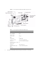
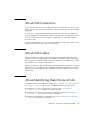
Component Layout
The Sun StorageTek SAS RAID External HBA is a SAS RAID HBA with these
features.
Chapter 1
HBA Overview
3
FIGURE 1-1
Sun StorageTek SAS RAID External HBA Component Layout
TABLE 1-1
Sun StorageTek SAS RAID External HBA Features
Feature
Specification
Form Factor
Low-profile MD2
Bus compatibility
PCIe
PCIe bus width
x8
PCIe bus speed
2.5 Gb/s
PHYs
8
Standard cache
256 MB DDR2
Connectors, external
Two mini-SAS x4 (SFF-8088)
RAID levels
0, 1, 1E, 10, 5, 5EE, 50, 6, 60, JBOD
Maximum number of volumes
24
Simple Volume
Disk Drives
SATA, SATA II, SAS
Maximum number of disk
drives
8 (or up to 100 with expanders)
Hot-spares
4
Sun StorageTek SAS RAID HBA Installation Guide Eight-Port, External HBA • November 2009
TABLE 1-1
Sun StorageTek SAS RAID External HBA Features
Feature (Continued)
Specification (Continued)
Enclosure Support
I2C and SGPIO (Serial General Purpose Output)
Automatic Failover
Onboard speaker
Audible alarm
Battery Backup Module
ABM-800
Operating System and Technology
Requirements
This HBA supports, at a minimum, the following operating system and technology
versions.
TABLE 1-2
Supported Operating System Versions
Operating
System/Technology
Supported Versions (minimum)
Solaris 10 OS for the x64
and x86 (32-bit and 64bit) platforms
• Solaris 10 10/08 (s10u6)
• Solaris 10 5/08 (s10u5)
• Solaris 10 8/07 (s10u4)
Solaris 10 OS for the
SPARC (64-bit) platform
Solaris 10 10/08 (s10u6)
Linux OS
•
•
•
•
RHEL 5 Server, 32-bit and 64-bit
RHEL 5 Advanced Platform, 32-bit and 64-bit
Red Hat Enterprise Linux (RHEL) 4 ES, 32-bit and 64-bit
RHEL 4 AS Update 5, 32-bit and 64-bit
Chapter 1
HBA Overview
5
TABLE 1-2
Supported Operating System Versions (Continued)
Operating
System/Technology
Supported Versions (minimum)
• SUSE Linux Enterprise Server (SLES) 10
• SUSE Linux Enterprise Server (SLES) 9, SP4
VMware® Technology
ESX Server version 3.0.2, Update 1 (driver support only; storage
management must be done through the command-line interface and
BIOS utility. For more information, see the Uniform Command-Line
Interface User’s Guide at:
http://docs.sun.com/app/docs/prod/stortek.raid.hba#h
ic
Microsoft Windows OS
•
•
•
•
Windows
Windows
Windows
Windows
Server
Server
Server
Server
2008
2008
2003
2003
Enterprise Edition, 32-bit or 64-bit
Standard Edition, 32-bit or 64-bit
Enterprise Edition, 32-bit or 64-bit
Standard Edition, 32-bit or 64-bit
Note – For up-to-date operating system version support, visit
http://support.intel.com/support/go/sunraid.htm.
System Interoperability
This section provides information about selected platforms and storage systems that
are compatible with the HBA. This section contains the following subsections:
■
“Host Platform Support” on page 6
■
“Server Support” on page 7
■
“Storage System Support” on page 7
■
“Software Support” on page 8
Host Platform Support
The HBA is supported by the following platforms:
6
■
1 GB of RAM, at minimum
■
Available compatible PCI-Express x8 slot
■
100 MB of free disk drive space
Sun StorageTek SAS RAID HBA Installation Guide Eight-Port, External HBA • November 2009
Server Support
TABLE 1-1 lists the servers that the HBA supports.
TABLE 1-1
Supported Servers
Server
Supported OS/Technology
SPARC Servers
Sun Fire™ V445 server
Solaris
Sun Fire V215 and V245 servers
Solaris
Sun Fire T1000 and T2000 servers
Solaris
Sun SPARC Enterprise M3000 server
Solaris
Sun SPARC Enterprise M4000/M5000 FF1,FF2
Solaris
Sun SPARC Enterprise M8000/M9000 servers 32bit, 64-bit
Solaris
Sun SPARC Enterprise T5120 and T5220 servers
Solaris
Sun SPARC Enterprise T5140 and T5240 servers
Solaris
Sun SPARC Enterprise T5440 server
Solaris
Sun Ultra U45 server
Solaris
x64 Servers
Sun Fire X2100 M2 server
Solaris, Linux, VMware, and Windows
Sun Fire X2200 M2 server
Solaris, Linux, VMware, and Windows
Sun Fire X2250 server
Solaris, Linux, VMware, and Windows
Sun Fire X4150 server
Solaris, Linux, VMware, and Windows
Sun Fire X4240 server
Solaris, Linux, VMware, and Windows
Sun Fire X4250 server
Solaris, Linux, VMware, and Windows
Sun Fire X4450 server
Solaris, Linux, VMware, and Windows
Sun Fire X4540 server
Solaris, Linux, VMware, and Windows
Sun Fire X4600 and X4600 M2 servers
Solaris, Linux, VMware, and Windows
Sun Fire X4100 M2 and X4200 M2 servers
Solaris, Linux, VMware, and Windows
Storage System Support
The HBA supports the following storage systems:
■
Sun Storage J4200
Chapter 1
HBA Overview
7
■
Sun Storage J4400
■
Sun Storage J4500
Software Support
TABLE 1-3 lists the software applications that are supported by this HBA.
TABLE 1-3
8
Software Support
Software
Supported OS
VERITAS Software Foundation 5.0
Solaris
Sun StorEdge Enterprise Backup Software
6.0B/7.0/7.1
Solaris, Linux, and Windows
VERITAS NetBackup 6.0
Solaris, Linux, and Windows
ZFS
Solaris, Linux, and Windows
Sun StorageTek SAS RAID HBA Installation Guide Eight-Port, External HBA • November 2009
CHAPTER
2
Hardware Installation and Removal
This chapter explains how to install and remove the Sun StorageTek SAS RAID
External HBA, and how to connect external disk drive enclosures.
The chapter contains the following sections:
■
“Observing ESD and Handling Precautions” on page 9
■
“To Prepare for Hardware Installation” on page 10
■
“To Install the Battery Backup Module” on page 12
■
“To Install the HBA” on page 15
■
“Connecting Disk Drive Enclosures” on page 16
■
“Testing the HBA Installation” on page 17
■
“Removing the Hardware” on page 22
Observing ESD and Handling
Precautions
Caution – Damage to the HBA can occur as the result of careless handling or
electrostatic discharge (ESD). Always handle the HBA with care to avoid damage to
electrostatic sensitive components.
To minimize the possibility of ESD-related damage, use both a workstation antistatic
mat and an ESD wrist strap. You can get an ESD wrist strap from any reputable
electronics store or from Sun as part number #250-1007. Observe the following
precautions to avoid ESD-related problems:
■
Leave the HBA in its antistatic bag until you are ready to install it in the system.
9
■
Always use a properly fitted and grounded wrist strap or other suitable ESD
protection when handling the HBA and observe proper ESD grounding
techniques.
■
Hold the HBA by the edge of the PCB, not the connectors.
■
Place the HBA on a properly grounded antistatic work surface pad when it is out
of its protective antistatic bag.
Preparing for Hardware Installation
▼ To Prepare for Hardware Installation
1. Read “Safety Agency Compliance Statements” on page 99.
2. Familiarize yourself with the physical features of the Sun StorageTek SAS
RAID External HBA and the RAID levels that it supports.
See “Component Layout” on page 3.
3. Ensure you have a supported external disk drive enclosure (see “Storage System
Support” on page 7) with the right quantity of disk drives for the RAID level
you want to use for the arrays (see “Selecting the Best RAID Level” on page 83).
All the disk drives must have the same performance level. You can use differentsized disk drives in the array, but the array will be limited to the capacity of the
smallest and slowest disk drive.
For more information, refer to the Sun StorageTek RAID Manager Software User’s
Guide or online Help.
The Sun StorageTek SAS RAID External HBA supports both SAS and SATA disk
drives.
4. Ensure that you have the proper cables for the HBA and external disk drive
enclosure.
You will need at least one SAS cable that has a x4 SFF-8088 connector on the host
end that will connect to the HBA (the connector on the target end depends on the
connection requirement of the hard disk drive enclosure). Use only Sun-provided
SAS cables (provided with your Sun system at time of purchase). For more
information or to purchase cables for your Sun system, visit the Sun web site at
http://www.sun.com. Cable connectors are keyed so that you cannot insert
them incorrectly.
10
Sun StorageTek SAS RAID HBA Installation Guide Eight-Port, External HBA • November 2009
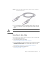
FIGURE 2-1
External SAS Cable (SFF-8088 Connector) Used to Connect to an External
Hard Disk Drive Enclosure
5. If you are installing the HBA into a full-height computer chassis, replace the
original low-profile bracket with the full-height bracket included in the HBA
ship kit.
Caution – Handle the HBA by its bracket or edges only.
Installation Task Map
The following procedure describes the tasks to perform in order to install the HBA
on an existing operating system (OS):
1. Install the battery backup module (BBU).
See “Installing the Battery Backup Module” on page 12.
2. If you are installing on an x64 system, skip to the next step. If you are installing
on a SPARC system, use the Open Boot Prompt (OBP) to make note of the
current devices on the system.
See “Verifying the Current Devices on a SPARC System” on page 14.
3. Install and connect the HBA and disk drives.
See “Installing the HBA” on page 15.
Chapter 2
Hardware Installation and Removal
11
4. Install the HBA driver.
See “Installing the Driver on an Existing Operating System” on page 25.
5. Install the Sun StorageTek RAID Manager GUI and begin to manage data
storage.
Use the Sun StorageTek RAID Manager CD provided in the HBA ship kit to
install the Sun StorageTek RAID Manager software. For information about
installing and using the software, see the Sun StorageTek RAID Manager Software
User’s Guide. For the latest version of the software, go to:
http://support.intel.com/support/go/sunraid.htm.
Installing the Battery Backup Module
Tools required:
■
Small Phillips head screw driver to tighten the screws
■
(Suggested) Small needle nose pliers or tweezers
■
ESD wrist strap
▼ To Install the Battery Backup Module
1. Attach an ESD wrist strap.
See “Observing ESD and Handling Precautions” on page 9.
2. Lay the top square piece of packing foam from the ship kit on your work
surface, smooth side up.
3. Take the HBA out of the antistatic bag and set it on the packing foam with the
heat sink facing up.
4. Slightly lift the HBA, and from underneath it, insert three plastic screws from
the BBU kit through the following three mounting holes in the HBA:
12
■
The bottom two holes. These are about 1 inch and 3 inches from the right edge
of the HBA.
■
The top right hole. This is about 1 inch from the right edge of the HBA.
Sun StorageTek SAS RAID HBA Installation Guide Eight-Port, External HBA • November 2009
FIGURE 2-2
Installing the BBU
5. Place a spacer over each screw.
The BBU connector on the HBA is between the two screw holes closest to the
right edge of the HBA.
6. Line up the BBU connector on the BBU module with the connector on the HBA.
The screws you inserted will line up with matching holes in the BBU.
7. Gently press down on the right edge of the BBU module until the connectors
click into place.
Caution – DO NOT force the connection. If a gentle push does not mate the
connectors, realign the components and try again.
8. Obtain the three nuts from the BBU kit, and for each nut, do the following:
a. Place the nut onto the screw and hold the nut in place.
Chapter 2
Hardware Installation and Removal
13
b. With the Phillips head screw driver, reach underneath the HBA and, while
holding the nut in place with your other hand (or with needle nose pliers or
tweezers), screw the plastic screw into the nut.
c. Repeat Step a - Step b for the remaining nuts.
Note – If you are unable to place a nut onto the screw that is close to the heat sink,
use a small pair of needle nose pliers or tweezers.
Caution – Do not over-tighten the nuts.
Verifying the Current Devices on a
SPARC System
If you are installing on a non-SPARC system, skip to “Installing the HBA” on
page 15.
▼ To Verify the Current Devices
1. Enter the Open Boot Prompt (OBP) and use the show-disks command to list
the current devices.
{0} ok show-disks
a) /pci@0/pci@0/pci@2/scsi@0/disk
b) /pci@0/pci@0/pci@1/pci@0/pci@1/pci@0/usb@0,2/storage@2/disk
q) NO SELECTION
Enter Selection, q to quit: q
{0} ok
Note – Device paths might vary from this example, depending on the SPARC
system you are using and into which PCI-E slot the card is plugged.
2. Take note of the devices.
This will help you determine which device is the HBA after you install the HBA.
14
Sun StorageTek SAS RAID HBA Installation Guide Eight-Port, External HBA • November 2009
Installing the HBA
Note – For the Sun SPARC Enterprise T5120, T5220, T5140, and T5240 servers,
contact Sun support to install the HBA.
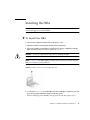
▼ To Install the HBA
1. Turn off the computer and disconnect the power cord.
2. Open the cabinet, following the manufacturer instructions.
3. Select an available x8 PCI-Express expansion slot that is compatible with the
HBA and remove the slot cover as shown in FIGURE 2-3.
Caution – Touch a grounded metal object before handling the HBA.
Note –
FIGURE 2-3 may differ slightly from the Sun StorageTek SAS RAID External
HBA and computer system hardware.
FIGURE 2-3
Remove Slot Cover from Expansion Slot
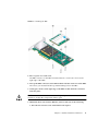
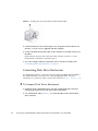
4. As shown in FIGURE 2-4, insert the HBA into the PCI-Express expansion slot and
press down gently but firmly until it clicks into place.
When installed properly, the HBA will appear level with the expansion slot.
Chapter 2
Hardware Installation and Removal
15
FIGURE 2-4
Installing the Sun StorageTek SAS RAID External HBA
5. Secure the bracket in the x8 PCI Express slot, using the retention device (for
instance, a screw or lever) supplied with the computer.
6. Connect the disk activity LED cable of the computer to the LED connector on
the HBA.
Ensure that the positive lead of the LED cable (usually a red wire or a wire
marked with a red stripe) is attached to pin 1.
7. Close the computer cabinet, reattach the power cord, then continue with
“Connecting Disk Drive Enclosures” on page 16.
Connecting Disk Drive Enclosures
Use high-quality cables to connect the Sun StorageTek SAS RAID External HBA to
the external disk drive enclosures. Use only Sun-supplied cables. For more
information or to purchase cables, visit the Sun web site at http://www.sun.com.
▼ To Connect Disk Drive Enclosures
1. Install the SAS or SATA disk drives into the external disk drive enclosure,
following the instructions in the enclosure documentation.
2. Use external SAS cables (FIGURE 2-1) to attach the HBA to the external disk
drive enclosure.
16
Sun StorageTek SAS RAID HBA Installation Guide Eight-Port, External HBA • November 2009
Testing the HBA Installation
This section contains the following subsections:
■
“To Test the HBA Installation on a SPARC System” on page 17
■
“To Test the HBA Installation on an x64 System” on page 20
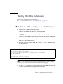
▼ To Test the HBA Installation on a SPARC System
1. Power-up the computer and storage systems.
a. Ensure that all hard disk drives are securely installed.
b. Connect all power cords securely and plug them into the proper power
sources.
c. Power-on the disk drive enclosure, and verify that all available HDD status
indicators are normal for the storage enclosure(s) that they are in.
d. Power-on the computer system.
2. Enter the Open Boot Prompt (OBP) and use the show-disks command to list
the current devices.
In the following example, the HBA is the first device that is listed.
{0} ok show-disks
a) /pci@0/pci@0/pci@8/pci@0/pci@8/scsi@0/disk
b) /pci@0/pci@0/pci@2/scsi@0/disk
c) /pci@0/pci@0/pci@1/pci@0/pci@1/pci@0/usb@0,2/storage@2/disk
q) NO SELECTION
Enter Selection, q to quit: Chassis | critical: V_VCORE at /SYS/MB has
exceeded high warning threshold.
valid choice: a...c, q to quit q
Note – Device paths might vary from this example, depending on which SPARC
system you are using and into which PCI-E slot the card is plugged.
3. Use the select command to select the device node for the HBA and follow the
on-screen instructions by pressing Enter when prompted.
Chapter 2
Hardware Installation and Removal
17
Note – When you run this command, omit /disk from the HBA device path, as
shown in the following example.
{0} ok select /pci@0/pci@0/pci@8/pci@0/pci@8/scsi@0
Waiting for AAC Controller to start: . . . . . . . Started
Config Changes:
1 ->One or more device either moved or removed
or not responding or added
Press <ENTER> to accept current config changes - with in 30 seconds
(Default - Ignore changes and check the setup)
<ENTER> Pressed. Current Config is accepted
4. To display the firmware version on the HBA, use the show-version command.
{0} ok show-version
AAC Kernel Version: 15815
{0} ok
18
Sun StorageTek SAS RAID HBA Installation Guide Eight-Port, External HBA • November 2009
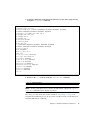
5. To display additional configuration information, list the device properties by
using the .properties command.
{0} ok .properties
firmware-version 15815
assigned-addresses 820f0010 00000000 00e00000 00000000 00200000
820f0030 00000000 00d00000 00000000 00080000
compatible pciex9005,285.108e.286.9
pciex9005,285.108e.286
pciex9005,285.9
pciex9005,285
pciexclass,010400
pciexclass,0104
model AAC,285
reg 000f0000 00000000 00000000 00000000 00000000
030f0010 00000000 00000000 00000000 00200000
version 0.00.01
wide 00000010
device_type scsi-2
name scsi
fcode-rom-offset 0000fe00
port-type PCIE-Endpoint
interrupts 00000001
cache-line-size 00000010
class-code 00010400
subsystem-id 00000286
subsystem-vendor-id 0000108e
revision-id 00000009
device-id 00000285
vendor-id 00009005
{0} ok
6. Return to the root node by using the unselect-dev command.
{0} ok unselect-dev
Note – At this point, there are no volumes created and the output from a probescsi-all command will not display any drives.
If no errors or issues were discovered, continue to “Next Steps” on page 22 to
complete the installation process. If any issues were discovered, correct them and
retest the HBA before continuing.
Chapter 2
Hardware Installation and Removal
19
▼ To Test the HBA Installation on an x64 System
1. Power-up the computer and storage systems:
a. Ensure that all hard disk drives are securely installed.
b. Connect all power cords securely and plug them into the proper power
sources.
c. If applicable, power-on the disk drive enclosure, and verify that all available
HDD status indicators are normal for the storage enclosure(s) that they are
in.
d. Power-on the computer system.
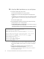
2. Enter the BIOS RAID Configuration Utility (RCU) by doing the following:
a. During POST, press Ctrl + A when prompted.
b. As the computer continues its startup sequence, review the boot messages to
determine the firmware version on the HBA.
Boot messages, similar to those shown in the following example, are displayed
that indicate the firmware version (in this example, the FW build is 15815).
Adaptec RAID BIOS V5.3-0 [Build 15815]
(c) 1998-2008 Adaptec, Inc. All Rights Reserved
<<<Press <Ctrl><A> for Adaptec RAID
Adaptec RAID Configuration Utility will be invoked after initialization.
Booting the Controller Kernel....Controller started
Controller #00: Sun STK RAID EXT at PCI Slot:02, Bus:04, Dev:00, Func:00
Waiting for Controller to Start....Controller started
Controller monitor V5.3-0[15815], Controller kernel V5.3-0[15815]
Battery Backup Unit Present
Controller POST operation successful
Controller Memory Size: 256 MB
Controller Serial Number: 00721EC0006
Controller WWN: 5000E0CE21907000
No Logical Drives Found
c. When the utility starts, review the list of HBAs installed on the computer.
d. If more than one HBA is listed, select the one you wish to test and press
Enter.
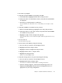
3. Enter the Array Configuration Utility (ACU) by highlighting Array
Configuration Utility and then pressing Enter.
You might see a screen indicating Configuration Change. This is normal for a
newly installed HBA and targets.
20
Sun StorageTek SAS RAID HBA Installation Guide Eight-Port, External HBA • November 2009
4. Press Enter as prompted.
5. Verify that all attached HDDs are detected by the HBA:
a. At the Main Menu, highlight Initialize Drives and press Enter.
b. In the Select drives for initialization column, verify that all attached HDDs
are displayed.
c. Select drives to initialize them for verification.
You can initialize all of the drives now or wait until you are ready to create
arrays.
6. Verify that all HDDs are available for array creation:
a. Return to the Main Menu page, highlight Create Array, and press Enter.
b. In the Select drives to create Array column, verify that all the attached HDDs
are available for array creation.
c. Highlight a couple of drives and press the space bar.
Verify that the drives are moved into the right column in preparation for array
creation.
7. Press Esc and exit.
You will create arrays later.
8. Test the alarm for the HBA by doing the following:
a. Press Esc until you reach the controller Options menu.
b. Highlight Serial Select and press Enter.
c. Highlight Controller Configuration and press Enter.
d. Highlight Alarm Control… and press Enter.
e. Highlight Test and press Enter.
Verify a 3-second audible alarm.
9. Verify that all target devices are present by doing the following:
a. Press Esc until you reach the controller Options menu.
b. Highlight Disk Utilities and press Enter.
You will see an indication that the HBA is scanning SAS devices.
c. After the scanning completes, verify that all attached target devices are
displayed, including HDDs and any enclosure management devices, if
appropriate for your storage configuration.
Chapter 2
Hardware Installation and Removal
21
d. Press Esc to exit.
If any issues were discovered, correct them and retest the HBA before continuing.
Next Steps
To complete the installation, continue with “Installing the Driver on an Existing
Operating System” on page 25.
Removing the Hardware
The following instructions describe the tasks required to remove the HBA. If you
need to replace a failed HBA, remove the hardware, as described in this section, and
see “Best Practices For Replacing an HBA” on page 70.
Caution – Never remove the HBA when an attached array is in the process of
rebuilding a logical drive from a 'Degraded' state.
▼ To Prepare the HBA for Removal
1. If the computer is running the OS, halt all I/O activity to the HBA.
2. Complete all transactions being done by the HBA such as migrations, rebuilds,
verifications, and so on.
3. Properly log out of the OS and shut down the computer.
4. Unplug the computer.
5. Power-down the external disk drive enclosure for the HBA.
6. Disconnect the SAS cable(s) from the HBA.
22
Sun StorageTek SAS RAID HBA Installation Guide Eight-Port, External HBA • November 2009
▼ To Remove the HBA
1. Remove the retention mechanism (screw, clip, and so on) that is securing the
HBA bracket to the chassis.
2. Hold the upper portion of the bracket with one hand and the rear of the HBA
with the other hand.
3. Pull straight up until the HBA clears the PCI Express expansion slot.
4. Lift the HBA from the computer chassis.
Chapter 2
Hardware Installation and Removal
23
24
Sun StorageTek SAS RAID HBA Installation Guide Eight-Port, External HBA • November 2009
CHAPTER
3
Installing the Driver on an Existing
Operating System
This chapter describes how to install the HBA driver on an existing operatin system.
The chapter contains the following sections:
■
“Preparing to Install the HBA Driver” on page 25
■
“Installing the Driver on an Existing OS” on page 26
Preparing to Install the HBA Driver
Before you begin, prepare to install the driver by doing the following.
1. Install and connect the HBA and disk drives.
See “Hardware Installation and Removal” on page 9.
Note – For up-to-date operating system version support, visit
http://support.intel.com/support/go/sunraid.htm.
2. Obtain the driver CD from the HBA ship kit or obtain the latest version of the
driver at http://support.intel.com/support/go/sunraid.htm.
25
Installing the Driver on an Existing OS
The driver can be installed on various operating systems. This section contains the
following subsections:
■
“To Install the Driver on the Windows OS” on page 26
■
“To Install the Driver on the Red Hat or SUSE Linux OS” on page 26
■
“To Install the Driver on the Solaris OS on an x64 System” on page 27
■
“To Install the Driver on the Solaris OS on a SPARC System” on page 27
■
“To Install the Driver on VMware Technology” on page 28
▼ To Install the Driver on the Windows OS
1. Start or restart Windows.
The Found New Hardware Wizard opens and searches for the driver.
2. Insert the driver CD.
3. Select the source, and click Next.
4. Click Next, and click Next again.
5. Follow the on-screen instructions to complete the driver installation.
6. Remove the driver CD and restart the computer.
7. To configure and manage the hard disks, see the Sun StorageTek RAID Manager
Software User’s Guide at:
http://docs.sun.com/app/docs/prod/stortek.raid.hba#hic
▼ To Install the Driver on the Red Hat or SUSE
Linux OS
Note – The driver required by this HBA is provided with the RHEL 5 and SUSE 10
operating systems. The RHEL 5 and SUSE 10 operating systems require nothing
from the user. You do not need to perform the procedure in this section.
1. Insert the driver CD.
26
Sun StorageTek SAS RAID HBA Installation Guide Eight-Port, External HBA • November 2009
2. Mount the CD.
For example, to insert and mount a CD:
Red Hat: mount /dev/cdrom /mnt/cdrom
SUSE: mount /dev/cdrom /media/cdrom
3. Install the module RPM:
rpm -Uvh mount-point/xxx/yyy.rpm
Where mount-point is the specific mount point on the Linux system, xxx is the
driver path, and yyy.rpm is the rpm file.
4. Reboot the computer to ensure the driver loaded correctly.
5. Run fdisk, mkfs, and create mount points for any new disk drives.
6. To configure and manage the hard disks, see the Sun StorageTek RAID Manager
Software User’s Guide at:
http://docs.sun.com/app/docs/prod/stortek.raid.hba#hic
▼ To Install the Driver on the Solaris OS on an x64
System
This HBA supports, at a minimum, the Solaris 10 8/07 (s10u4) OS on an x64-based
system. The Solaris 10 8/07 OS requires nothing from the user. However, install the
latest patches from the http://www.sunsolve.sun.com web site after installing
the Solaris OS.
To configure and manage the hard disks, see the Sun StorageTek RAID Manager
Software User’s Guide at:
http://docs.sun.com/app/docs/prod/stortek.raid.hba#hic
▼ To Install the Driver on the Solaris OS on a
SPARC System
This HBA supports, at a minimum, the Solaris 10 10/08 (s10u6) OS on a SPARC
system. The Solaris 10 10/08 OS requires nothing from the user. However, install the
latest patches from the http://www.sunsolve.sun.com web site after installing
the Solaris OS.
To configure and manage the hard disks, see the Sun StorageTek RAID Manager
Software User’s Guide at:
http://docs.sun.com/app/docs/prod/stortek.raid.hba#hic
Chapter 3
Installing the Driver on an Existing Operating System
27
▼ To Install the Driver on VMware Technology
Note – The embedded driver provided by VMware ESX Server is suitable for most
applications. If an updated driver is needed, use the following procedure.
1. Start the computer, then insert the driver CD.
2. At the console screen of the VMware ESX Server, mount the CD.
For example:
mount –r /dev/cdrom /mnt/cdrom
3. Install the module RPM:
rpm –ivh /mnt/cdrom/xxx/yyy.rpm
where xxx is the driver path, and yyy.rpm is the rpm file.
4. Reboot the computer and remove the driver medium.
Note – The Sun StorageTek RAID Manager GUI is not supported with VMware
technology. To create and manage arrays, use the command-line interface and BIOS
utility. See the Uniform Command-Line Interface User’s Guide at:
http://docs.sun.com/app/docs/prod/stortek.raid.hba#hic
Next Steps
Do either of the following:
28
■
Install and use the Sun StorageTek RAID Manager GUI (unless you are using
VMware technology) to create arrays on the disk enclosure. See the Sun StorageTek
RAID Manager User’s Guide.
■
If you are using an x64 system, you can also use the BIOS utility to create arrays
on the disk enclosure. See “Using the BIOS RAID Configuration Utility” on
page 45.
Sun StorageTek SAS RAID HBA Installation Guide Eight-Port, External HBA • November 2009
CHAPTER
4
Known Issues
This chapter contains the latest supplementary information for the preceding
chapters in this guide. Specific Change Request (CR) identification numbers are
provided for service personnel, when necessary. This chapter contains the following
topics:
■
“Ship Kit Issues” on page 29
■
“BIOS Utility Issues” on page 30
■
“Performance Issues” on page 30
■
“JBOD Issues” on page 33
Ship Kit Issues
This section describes the known ship kit issue.
Some or All CDs Are Not Included in the HBA
Ship Kit
Workaround: You can obtain the latest drivers and software at:
http://support.intel.com/support/go/sunraid.htm
29
BIOS Utility Issues
The following are known issues with the BIOS RAID Configuration utility:
■
“Creating an Array With the BIOS Utility Changes the BIOS Boot Order” on
page 30
■
“Hot-Plug Functionality Does Not Work in the BIOS Utility” on page 30
Creating an Array With the BIOS Utility Changes
the BIOS Boot Order
Workaround: After creating the array, check the BIOS settings to verify the correct
boot order and make changes as necessary. For more information, see “Best Practices
For Controlling the Boot Order of Logical Drives” on page 69.
Hot-Plug Functionality Does Not Work in the
BIOS Utility
Workaround: Hot-plugging of enclosures is not supported in the BIOS RAID
Configuration utility. Hot-plugging of SAS/SATA hard disk drives (HDDs) is
supported only within hard disk enclosures and only under the conditions specified
in “Understanding Hot-Plug Limitations and Conditions Within the BIOS RAID
Configuration Utility” on page 46.
Performance Issues
This section contains the known performance issues:
30
■
“ZFS Forces a Flush of the NVRAM on the HBA When Completing Synchronous
Writes, Which Impacts Performance” on page 31
■
“The System Freezes When a Sun Storage 32GB SLC SATA Solid State Drive (SSD)
Is Configured In the HBA” on page 32
■
“A Space Usage Error Message Is Displayed When Trying to Expand an Existing
Volume” on page 32
Sun StorageTek SAS RAID HBA Installation Guide Eight-Port, External HBA • November 2009
■
“Cannot Access the HBA From the GUI Nor Access a LUN From the Host” on
page 33
ZFS Forces a Flush of the NVRAM on the HBA
When Completing Synchronous Writes, Which
Impacts Performance
Workaround: As of Solaris 10 8/07 (s10u4), you can prevent ZFS from issuing
SYNCHRONIZE CACHE commands to the NVRAM on the HBA by defining a ZFS
global setting in the Solaris /etc/system file. This setting improves ZFS
performance and is appropriate for Solaris 10 8/07. However, this setting will likely
not be required in subsequent releases of the Solaris OS. The setting must only be
used if all devices managed by ZFS are managed with non-volatile caches.
To define the ZFS global setting, do the following:
1. On the system in which the HBA is installed, add the following line to the
Solaris /etc/system file:
set zfs:zfs_nocacheflush=1
Note – This global setting affects all ZFS file systems on the system in which the
HBA is installed. Keep in mind that you must not define this setting if ZFS is
managing any disks with volatile caching, as the setting can put data at risk on those
disks.
2. Reboot the system.
For more information about how to reboot the system, see your system
documentation.
Chapter 4
Known Issues
31
The System Freezes When a Sun Storage 32GB
SLC SATA Solid State Drive (SSD) Is Configured
In the HBA
CR 6806467
Issue: This occurs because the HBA has firmware prior to version 16732 installed on
it and the Sun Storage 32GB SLC SATA SSD has firmware version 8626 or earlier
installed on it.
Workaround: Do the following:
1. Upgrade the HBA firmware to version 16732, at minimum.
You can obtain the latest HBA firmware at:
http://support.intel.com/support/go/sunraid.htm
2. Power cycle the HBA host system.
3. Upgrade the SSD firmware to version 8850, at minimum.
You can obtain the latest SSD firmware at: http://www.sunsolve.sun.com
4. Power cycle the SSD.
A Space Usage Error Message Is Displayed When
Trying to Expand an Existing Volume
CR 6871696
Issue: When attempting to grow or expand a volume on a device that has enough
storage space to do so, the following error message might be displayed:
The specified operation failed because there was not enough
space on the specified device.
This error message occurs if the write cache setting is unkown on some of the drives
used by the HBA.
Workaround: Initialize the drive and then grow the volume onto that initialized
drive. To avoid encountering this error message, initialize all ready drives before the
drives are used by the HBA.
32
Sun StorageTek SAS RAID HBA Installation Guide Eight-Port, External HBA • November 2009
Cannot Access the HBA From the GUI Nor Access
a LUN From the Host
CR 6820225
Workaround: Reboot the host system on which the HBA resides.
JBOD Issues
The following are known issues with JBODs:
■
“Difficulty With Detecting Disks in a JBOD” on page 33
■
“During System Boot Time, JBOD Affiliations Cause HBA Inoperability and
System Panic” on page 34
■
“After Upgrading Firmware on a JBOD, the JBOD Is No Longer Detected by the
GUI” on page 34
■
“The Solaris System Panics After Attaching a JBOD to the HBA” on page 34
Difficulty With Detecting Disks in a JBOD
Workaround: If you have difficulty detecting disks in a given JBOD, do the
following:
1. Make sure the JBOD has been power cycled to clear affiliations.
For more information about affiliations, see “Connecting a JBOD With SATA
Disks” on page 67.
2. If the JBOD has not been power cycled, disconnect the JBOD, power cycle it,
and reconnect the JBOD.
3. If you are still not seeing disks, disconnect the JBOD and fully bring up the
host system with the JBOD cable unplugged.
This ensures that no disks are connected to the card.
4. Start the Sun StorageTek RAID Manager GUI and, from the GUI, confirm the
disks are not connected to the card.
5. Reconnect the cable and verify in the GUI that the disks are displayed and
reconnected to the card.
Keep in mind that the more disks on a given channel, the longer the disks will
take to be displayed in the GUI. It may take several minutes.
Chapter 4
Known Issues
33
During System Boot Time, JBOD Affiliations
Cause HBA Inoperability and System Panic
CR 6723287
Issue: If you connect a JBOD with SATA disks to an HBA, and the JBOD has
affiliations, the HBA might become inoperable and the Solaris system might panic
during boot time. This occurs when the system has an old firmware version.
Workaround: Do either of the following:
■
Upgrade the HBA firmware to version 15872, at minimum. To obtain the latest
version of the firmware, go to:
http://support.intel.com/support/go/sunraid.htm
■
If you do not want to immediately update the HBA firmware version, before you
connect any JBODs with SATA disks to an HBA, power cycle the JBODs to clear
any affiliations. For more information about troubleshooting JBODs, see
“Difficulty With Detecting Disks in a JBOD” on page 33. For more information
about affiliations, see “Connecting a JBOD With SATA Disks” on page 67.
After Upgrading Firmware on a JBOD, the JBOD
Is No Longer Detected by the GUI
CR 6792854
Issue: If you incorrectly move cables connected to the JBOD during the JBOD
firmware upgrade process, the GUI can no longer detect the JBOD.
Workaround: Before upgrading firmware on a JBOD, review “Best Practices For
Switching Cables and Making New Connections” on page 66 and “Best Practices For
Cabling to Disk Enclosures” on page 67. If you have already moved cables from the
JBOD during the firmware upgrade, see “Difficulty With Detecting Disks in a JBOD”
on page 33.
The Solaris System Panics After Attaching a JBOD
to the HBA
CR 6818045
Issue: This occurs if a JBOD that is already attached to the HBA has incoming IO
requests running while you are trying to attach the new JBOD.
Workaround: Quiesce IO on the HBA prior to attaching the new JBOD to the HBA.
34
Sun StorageTek SAS RAID HBA Installation Guide Eight-Port, External HBA • November 2009
Chapter 4
Known Issues
35
36
Sun StorageTek SAS RAID HBA Installation Guide Eight-Port, External HBA • November 2009
APPENDIX
A
Configuration Rules
This appendix provides configuration rules for the Sun StorageTek SAS RAID
External HBA.
Note – Use only Sun-approved devices and cabling with the Sun StorageTek SAS
RAID External HBA.
The appendix contains the following sections:
■
“Target Devices” on page 37
■
“Cabling” on page 38
Target Devices
The following rules apply for supported target devices:
■
■
Enclosures:
■
SAS/SATA JBODs
■
SAS/SATA JBODs with SES-2 enclosure management support
■
Sun Storage J4500 JBODs - Maximum of two per HBA (one on each wideport)
or two cascading per HBA (two cascaded down one wideport)
■
Sun Storage J4200 JBODs - Maximum of eight cascading per HBA (four
cascaded down each wideport)
SAS/SATA HDDs:
■
128 HDDs maximum per HBA via SAS expander
37
Note – Mixing SATA and SAS HDDs in the same logical RAID array is not
supported. Although it is not an unsupported configuration, it is also highly
recommended that SAS and SATA HDDs not be mixed in the same enclosure.
Cabling
38
■
SAS external cable with SFF-8088 host-side connector (provided with your system)
■
Maximum recommended length of 6 meters
Sun StorageTek SAS RAID HBA Installation Guide Eight-Port, External HBA • November 2009
APPENDIX
B
HBA Specifications
This appendix provides specifications for the Sun StorageTek SAS RAID External
HBA. The appendix contains the following sections:
■
“Physical Dimensions” on page 39
■
“Environmental Specifications” on page 40
■
“DC Power Requirements” on page 40
■
“Current Requirements” on page 40
■
“Performance Specifications” on page 40
■
“Connector Pin Definitions” on page 41
Physical Dimensions
Meets PCI low-profile MD2 specification.
■
Height: 67 mm
■
Length: 167 mm
39
Environmental Specifications
Note – With a Battery Backup Unit (BBU), the ambient temperature must not exceed
40 ˚C
TABLE B-1
Environmental Specifications
Ambient temperature without forced airflow
0 ˚C to 40 ˚ C
Ambient temperature with forced airflow
0 ˚C to 55 ˚ C
Relative humidity
10% to 90%, noncondensing
Altitude
Up to 3,000 meters
Note – Forced airflow is recommended.
DC Power Requirements
PCI-Express, DC Voltage 3.3 V 9%, 12 V 8%
Current Requirements
1.04 A @ 3.3 VDC; 0.98 A @ 12.0 VDC
Performance Specifications
The Serial Attached SCSI [SAS] bus defines these layers:
40
Sun StorageTek SAS RAID HBA Installation Guide Eight-Port, External HBA • November 2009
■
Physical layer: Consists of two sets of differential lines, one receive set and one
transmit set [4-wire total]. This layer defines the cable, connector, and transceiver
[Transmitter / Receiver] characteristics.
■
PHY layer: Connects the differential Transmitter and Receiver circuits [ICs] to the
Physical Layer.
■
Link layer
■
Port layer
■
Application layer
The external connector accepts 4 physical links and the cable may hold between 1
and 4 physical links. Internal connectors are defined and two data rates are defined:
1.5 Gbps and 3.0 Gbps over a 100 ohm [+ 15 ohm] differential impedance cable.
SAS uses the Serial ATA physical interface, including the connector receptacle and
connector plugs. SAS transmits data using 8B/10B at a maximum level of 1.2 volts
[Tx voltage = 800-1600mV], [Rx voltage = 275-1600mV]. SAS uses big-endian, while
SATA uses little-endian byte ordering. SAS uses a 32 bit CRC. SAS uses LVDS.
Connector Pin Definitions
SAS Pin-Out
Two types of ports are defined: A Narrow Port communicates over a narrow link and
contains only one transmit/receive pair, and a Wide Port communicates over a wide
link and contains more than one transmit/receive pair. The ports reside in the PHY
layer, and the link resides in the physical layer.
TABLE B-2
SAS Pin-Out
Signal Name
1 Physical Link
2 Physical Links 3 Physical Links 4 Physical Links
Rx 0+
S1
S1
S1
S1
Rx 0-
S2
S2
S2
S2
Rx 1+
N/A
S3
S3
S3
Rx 1-
N/A
S4
S4
S4
Rx 2+
N/A
N/A
S5
S5
Rx 2-
N/A
N/A
S6
S6
Rx 3+
N/A
N/A
N/A
S7
Appendix B
HBA Specifications
41
TABLE B-2
SAS Pin-Out
Signal Name
1 Physical Link
2 Physical Links 3 Physical Links 4 Physical Links
Rx 3-
N/A
N/A
N/A
S8
Tx 3-
N/A
N/A
N/A
S9
Tx 3+
N/A
N/A
N/A
S10
Tx 2-
N/A
N/A
S11
S11
Tx 2+
N/A
N/A
S12
S12
Tx 1-
N/A
S13
S13
S13
Tx 1+
N/A
S14
S14
S14
Tx 0-
S15
S15
S15
S15
Tx 0+
S16
S16
S16
S16
Signal Ground
G1 - G9
G1 - G9
G1 - G9
G1 - G9
Chassis Ground
Housing
Housing
Housing
Housing
SATA Pin-Out
The Serial ATA [SATA] bus is defined over two separate connectors, one connector
for the data lines and one for the power lines. A SATA hard drive may also have a
third connector for legacy PATA power connections. The PATA power connector may
be used in instead of the SATA power to supply a connection which is more rugged
and reliable then the SATA-1 power connection.
TABLE B-3
42
SATA Data Pin-Out
Pin #
Signal Name
Signal Description
1
GND
Ground
2
A+
Transmit +
3
A-
Transmit -
4
GND
Ground
5
B-
Receive -
6
B+
Receive +
7
GND
Ground
Sun StorageTek SAS RAID HBA Installation Guide Eight-Port, External HBA • November 2009
TABLE B-4
SATA Power Pin-out
Pin#
Signal Name
Signal Description
1
V33
3.3v Power
2
V33
3.3v Power
3
V33
3.3v Power, Pre-charge, 2nd mate
4
Ground
1st Mate
5
Ground
2nd Mate
6
Ground
3rd Mate
7
V5
5v Power, pre-charge, 2nd mate
8
V5
5v Power
9
V5
5v Power
10
Ground
2nd Mate
11
Reserved
-
12
Ground
1st Mate
13
V12
12v Power, Pre-charge, 2nd mate
14
V12
12v Power
15
V12
12v Power
Appendix B
HBA Specifications
43
44
Sun StorageTek SAS RAID HBA Installation Guide Eight-Port, External HBA • November 2009
APPENDIX
C
Using the BIOS RAID Configuration
Utility
The BIOS RAID Configuration utility is a BIOS-based utility that you can use to
create and manage controllers, disk drives and other devices, and arrays.
Note – If you are using a SPARC system, you cannot use the BIOS RAID
Configuration utility. Instead, use the Sun StorageTek RAID Manager graphical user
interface (GUI). For more information, see the Sun StorageTek RAID Manager Software
User’s Guide at:
http://docs.sun.com/app/docs/prod/stortek.raid.hba#hic
Note – If you are not an advanced user familiar with working in a computer BIOS,
do not use the BIOS RAID Configuration utility tools. Instead, use the Sun
StorageTek RAID Manager graphical user interface.
The appendix contains the following sections:
■
“Introduction to the BIOS RAID Configuration Utility” on page 46
■
“Understanding Hot-Plug Limitations and Conditions Within the BIOS RAID
Configuration Utility” on page 46
■
“Running the BIOS RAID Configuration Utility” on page 48
■
“Using the ACU to Create and Manage Arrays” on page 49
■
“Using the -Select Utility to Modify HBA Settings” on page 53
■
“Formatting and Verifying Disk Drives With the Disk Utilities” on page 56
■
“To Locate a Disk Drive With the Disk Utilities” on page 56
■
“To Identify a Disk Drive With the Disk Utilities” on page 58
■
“Viewing the BIOS-Based Event Log” on page 59
45
Introduction to the BIOS RAID
Configuration Utility
The BIOS RAID Configuration utility comprises these tools:
■
The Array Configuration Utility (ACU)—For creating and managing arrays, and
initializing and rescanning disk drives. See “Using the ACU to Create and Manage
Arrays” on page 49.
■
A -Select Utility—SerialSelect, or SATASelect, for modifying the HBA and disk
drive settings. See “Using the -Select Utility to Modify HBA Settings” on page 53.
■
Disk Utilities—For formatting or verifying disk drives. See “Formatting and
Verifying Disk Drives With the Disk Utilities” on page 56.
Understanding Hot-Plug Limitations
and Conditions Within the BIOS RAID
Configuration Utility
Hot-plugging of hard disk enclosures is not supported from within the BIOS RAID
Configuration utility. However, hot-plugging of SAS/SATA hard disk drives (HDDs)
is supported, but only within hard disk enclosures and under the following
conditions:
■
“Hot-Unplug Removal Conditions” on page 46
■
“Hot-Plug Addition Conditions” on page 47
■
“Hot-Unplug and Plug Replacement/Reinsertion Conditions” on page 47
Note – Hot-plugging of hard disk drives is NOT supported during periods when the
controller is busy performing actions on logical drives (building, rebuilding, or
migrating RAID volumes).
Hot-Unplug Removal Conditions
Hot-unplug, removal, of HDDs is supported under the following conditions:
46
Sun StorageTek SAS RAID HBA Installation Guide Eight-Port, External HBA • November 2009
■
The hard disk drive to be removed must not be a part of a logical device (its status
must be ‘available’).
■
After the hard disk drive is removed from the enclosure, you must perform a bus
scan by using the Rescan Drives option from the main menu of the Array
Configuration Utility (ACU).
■
You must confirm that the Disk Utility reports the correct configuration of the
attached target devices.
Hot-Plug Addition Conditions
Hot-plug, add, of HDDs is supported under the following conditions:
■
After the hard disk drive is added to the enclosure, you must perform a bus scan
by using the Rescan Drives option from the main menu of the ACU.
■
You must confirm that the Disk Utility reports the correct configuration of the
attached target devices.
Hot-Unplug and Plug Replacement/Reinsertion
Conditions
Hot unplug and plug, replace/reinsert, of HDDs is supported under the following
conditions:
■
The hard disk drive to be removed must not be a part of a logical device (its status
must be ‘available’).
■
If a hard disk drive is to be removed and replaced either into the same slot or a
different unused slot using the same disk drive or a new disk drive, you must
perform a bus scan between the removal and the replacement steps, as follows:
a. Remove the selected hard disk drive.
b. Complete a bus scan by using the Rescan Drives option in the ACU.
c. Confirm that the Disk Utility reports the correct configuration of attached
target devices
d. Replace/reinsert the hard disk (new or same) into the enclosure slot (same or
another unused slot).
e. Complete a bus scan by using the Rescan Drives option in the ACU.
f. Confirm that Disk Utility reports the correct configuration of attached target
devices.
Appendix C
Using the BIOS RAID Configuration Utility
47
Running the BIOS RAID Configuration
Utility
This section describes how to start and navigate through the BIOS RAID
Configuration utility. The section contains the following subsections:
■
“To Start the BIOS RAID Configuration Utility” on page 48
■
“To Navigate the BIOS RAID Configuration Utility” on page 48
▼ To Start the BIOS RAID Configuration Utility
1. If the HBA is connected to a RAID enclosure, power on the enclosure (or
enclosures) before you power on the computer.
2. Start or restart the computer.
3. When prompted, press Ctrl+A.
During boot up, if your system has insufficient memory the following message will
be displayed.
BIOS RAID Configuration Utility will load after system
initialization. Please wait... Or press <Enter> Key to attempt
loading the utility forcibly [Generally, not recommended]
Note – The first time you power on the computer after you install a new HBA, the
BIOS may display a configuration that does not match the system’s configuration.
This is normal.
▼ To Navigate the BIOS RAID Configuration
Utility
●
Use the arrows, Enter, Esc, and other keys on your keyboard to navigate
through the utility menus.
All the tools within the BIOS RAID Configuration utility are menu-based and
instructions for completing tasks are displayed on-screen.
48
Sun StorageTek SAS RAID HBA Installation Guide Eight-Port, External HBA • November 2009
Using the ACU to Create and Manage
Arrays
You can use the ACU, a tool of the BIOS RAID Configuration utility, to create and
manage arrays. This section contains the following subsections:
■
“To Start Using the ACU” on page 50
■
“To Create a New Array With the ACU” on page 50
■
“To Manage Existing Arrays With the ACU” on page 51
■
“To Make an Array Bootable With the ACU” on page 51
■
“To Initialize Disk Drives With the ACU” on page 52
■
“To Rescan Disk Drives With the ACU” on page 52
■
“To Perform a Secure Erase on Disk Drives With the ACU” on page 52
■
“To Stop a Secure Erase in Progress With the ACU” on page 53
Appendix C
Using the BIOS RAID Configuration Utility
49
▼ To Start Using the ACU
1. To open the ACU, start the BIOS RAID Configuration utility.
See “Running the BIOS RAID Configuration Utility” on page 48.
2. If you have more than one HBA, select the HBA that you want to manage, and
press Enter.
3. Select Array Configuration Utility, then press Enter.
4. Follow the on-screen instructions to create and manage arrays, and initialize,
rescan, and erase disk drives.
▼ To Create a New Array With the ACU
Note – You can create an array with the ACU and the Sun StorageTek RAID
Manager graphical user interface (GUI). However, it is a much quicker process to
create an array through the GUI than the ACU. Creating an array with the ACU
might take two to three times longer than creating an array with the GUI. For more
information, see the Sun StorageTek RAID Manager Software User’s Guide.
1. Select Create Arrays from the main ACU menu.
Only disk drives that can be used in a new array are available for selection. (Disk
drives must be initialized before they can be used in an array. See “To Initialize
Disk Drives With the ACU” on page 52 for more information.)
2. Use the Array Properties menu to modify the RAID level, size, name, stripe
size, and caching settings of the array.
Note – For more information about RAID levels and using disk drives to create
arrays, see “Selecting the Best RAID Level” on page 73.
Note – Creating a new array might change the BIOS boot order. Check the BIOS
settings to verify the correct boot order. For more information, see “Best Practices For
Controlling the Boot Order of Logical Drives” on page 69.
50
Sun StorageTek SAS RAID HBA Installation Guide Eight-Port, External HBA • November 2009
▼ To Manage Existing Arrays With the ACU
1. Select Manage Arrays from the main ACU menu.
2. From the Manage Arrays menu, do any of the following:
■
View the properties of an array.
Note – Failed drives are displayed in a different text color.
■
Make an array bootable. See “To Make an Array Bootable With the ACU” on
page 51.
■
Assign or remove hot-spares.
■
Delete an array.
Caution – Before deleting an array, back up the data to avoid permanently losing it.
▼ To Make an Array Bootable With the ACU
Note – You may need to change the system BIOS to modify the boot order. For more
information, refer to your computer documentation or see “Best Practices For
Controlling the Boot Order of Logical Drives” on page 69.
The Sun StorageTek SAS RAID External HBA always uses the lowest numbered array
as its bootable array.
1. Select Manage Arrays from the main ACU menu.
2. Select the array that you want to make bootable, then press Ctrl+B.
Note – You cannot make an array bootable while it is building, verifying, or
rebuilding.
The array number changes to Array 00, which makes this array the boot array for
the HBA.
3. Restart the computer.
Appendix C
Using the BIOS RAID Configuration Utility
51
▼ To Initialize Disk Drives With the ACU
If a disk drive is displayed grayed-out (unavailable for use in a new array), it may
need to be initialized.
●
Select Initialize Drives from the main ACU menu.
Caution – Do not initialize a disk drive that is part of an array. Initializing a disk
drive that is part of an array may make the array unusable. Back up all data from the
disk drive before you initialize it.
▼ To Rescan Disk Drives With the ACU
●
Select Rescan Drives from the main ACU menu.
▼ To Perform a Secure Erase on Disk Drives With
the ACU
When you perform a secure erase on a disk drive, all data on that disk drive is
completely and irretrievably eradicated. Secure erase performs three distinct writing
passes to the disk drive being erased—it does not just write zeros.
Performing a secure erase takes up to six times longer than clearing (or zeroing) a
disk drive. You may want to perform a secure erase only on disk drives that contain
confidential or classified information.
Note – To erase (or zero) a disk drive with non-classified information, you may
choose to format it (see “Formatting and Verifying Disk Drives With the Disk
Utilities” on page 56) instead, or clear it using Sun StorageTek RAID Manager
software—both options take much less time than the secure erase option.
●
Select Secure Erase from the main ACU menu, then select Y (yes).
To return to the main ACU menu once the secure erase has begun, press Esc. The
selected disk drive(s) cannot be used until the erase is complete.
52
Sun StorageTek SAS RAID HBA Installation Guide Eight-Port, External HBA • November 2009
▼ To Stop a Secure Erase in Progress With the ACU
1. In the main ACU window, select Secure Erase.
2. Select the disk drive being secure erased, then press Ctrl+Q.
The secure erase stops and the ACU returns to its main window.
Using the -Select Utility to Modify HBA
Settings
Included in the BIOS RAID Configuration utility is a tool for modifying the settings
of the HBA and the disk drives connected to it. This utility is called SerialSelect or
SATASelect. This section contains the following subsections:
■
“To Start Using a -Select Utility” on page 53
■
“To Apply Changes and Exit The -Select Utility” on page 53
■
“To Modify General HBA Settings With a -Select Utility” on page 54
■
“To Modify SAS-Specific HBA Settings With a -Select Utility” on page 55
▼ To Start Using a -Select Utility
●
Start the BIOS RAID Configuration utility (see “Running the BIOS RAID
Configuration Utility” on page 48), select the -Select utility, and press Enter.
▼ To Apply Changes and Exit The -Select Utility
1. Press Esc until you are prompted to exit.
If you modified any settings, you are prompted to save the changes before you
exit.
2. Select Yes to exit, then press any key to restart the computer.
Any changes you made take effect after the computer restarts.
Appendix C
Using the BIOS RAID Configuration Utility
53
▼ To Modify General HBA Settings With a -Select
Utility
Note – Default HBA settings are suitable for most computers. Do not change any
default settings.
●
Select Controller Configuration from the main -Select utility menu and change
the settings listed in the following table.
Some options may not be available for the HBA.
Note – Default settings are shown in bold type.
TABLE C-1
General HBA Settings
Option
Description
Drive’s Write Cache
When enabled, write cache is enabled on the disk drive. When
disabled, write cache is not used on the disk drive. It is
recommended that you disable write cache on the disk drive.
Caution - When write cache is enabled, there is the possibility of
data loss or corruption during a power failure.
54
Runtime BIOS
When enabled, the Sun StorageTek SAS RAID External HBABIOS
allows the HBA to act as a bootable device. Disabling the BIOS
allows another HBA to act as a bootable device.
Automatic Failover
When enabled, the Sun StorageTek SAS RAID External HBA
automatically rebuilds an array when a failed disk drive is
replaced. When disabled, the array must be rebuilt manually.
Array Background
Consistency Check
When enabled, the Sun StorageTek SAS RAID External HBA
constantly verifies a redundant array. Note that there may be a
significant performance reduction. Default is disabled.
BBS Support
When enabled in systems that support BBS, the Sun StorageTek
SAS RAID External HBA is presented as a bootable device in the
BIOS.
Array-based BBS
Support
When enabled in systems that support BBS, the Sun StorageTek
SAS RAID External HBA presents attached bootable devices up to
the BIOS for boot device selection. This is relevant for logical
arrays. Default is disabled.
Physical Drives
Display During POST
When enabled, connected disk drives are displayed during system
Power On Self Test (POST). Displaying the disk drives adds a few
seconds to the overall POST time. Default is disabled.
Sun StorageTek SAS RAID HBA Installation Guide Eight-Port, External HBA • November 2009
TABLE C-1
General HBA Settings
Option
Description
CD-ROM Boot
Support
When enabled, the system can be booted from a bootable CD.
Note—CDs are not supported by current software.
Removable Media
Devices Boot Support
When enabled, removable media devices, such as CD drives, are
supported.
Alarm Control
When enabled, the alarm sounds. Default is enabled.
Note—When the alarm is turned off (disabled), it will
automatically turn back on after a reboot.
SATA Native
Command Queuing
(NCQ)
When enabled, NCQ is enabled. Disable this feature if you want to
attach more than 48 SATA II disk drives. Only available with SATA
II disk drives.
▼ To Modify SAS-Specific HBA Settings With a Select Utility
In addition to the general settings listed on “To Modify General HBA Settings With a
-Select Utility” on page 54, the Sun StorageTek SAS RAID External HBA has SASspecific settings that can be modified if required. (For more information about SAS,
see “Introduction to Serial Attached SCSI” on page 85.)
●
Select PHY Configuration from the SerialSelect main menu and change the
settings listed in the following table.
Note – Default settings are shown in bold type.
TABLE C-2
SAS HBA Settings
Option
Description
PHY Rate
The data transfer rate between the HBA and devices. The default setting is
Auto, which allows the SAS card to adjust the data transfer rate as required.
CRC
Checking
When enabled, determines whether the HBA verifies the accuracy of data
transfer on the serial bus. Default setting is Yes (enabled). Set to No
(disabled) only if the HBA is connected to a device that does not support
CRC Checking.
SAS Address In a situation where you want each phy on a HBA to be in a different SAS
domain, this setting specifies a unique world-wide name for each phy.
Default is 0.
Note: This setting is for SAS address conflict resolution only and must
otherwise remain at its default value.
Appendix C
Using the BIOS RAID Configuration Utility
55
Formatting and Verifying Disk Drives
With the Disk Utilities
You can use the disk utilities to low-level format or verify the disk drives. (New disk
drives are low-level formatted at the factory and do not need to be low-level
formatted again.)
Caution – Before you format a disk drive, back up all data. Formatting destroys all
data on a disk drive.
This section contains the following subsections:
■
“To Format or Verify a Disk Drive With the Disk Utilities” on page 56
■
“To Locate a Disk Drive With the Disk Utilities” on page 56
■
“To Identify a Disk Drive With the Disk Utilities” on page 58
▼ To Format or Verify a Disk Drive With the Disk
Utilities
1. Start the BIOS RAID Configuration utility.
See “Running the BIOS RAID Configuration Utility” on page 48.
2. Select the HBA you want, then press Enter.
3. Select Disk Utilities.
4. Select the disk drive you want, then press Enter.
5. Select Format Disk or Verify Disk Media.
▼ To Locate a Disk Drive With the Disk Utilities
Note – This feature is only available with disk drives that have an activity LED.
You can use the Identify Drive feature to physically locate a disk drive by blinking
the LED.
56
Sun StorageTek SAS RAID HBA Installation Guide Eight-Port, External HBA • November 2009
1. Start the BIOS RAID Configuration utility.
See “Running the BIOS RAID Configuration Utility” on page 48.
2. Select the HBA you want, then press Enter.
3. Select Disk Utilities.
4. Select the disk drive you want, then press Enter.
5. Select Identify Drive, then press Enter.
6. When you have finished locating the disk drive, press any key to stop the
blinking.
Appendix C
Using the BIOS RAID Configuration Utility
57
▼ To Identify a Disk Drive With the Disk Utilities
You can identify disk drives by viewing the list of disk drives on the system. Only
physical drives that display during POST are shown.
1. Start the BIOS RAID Configuration utility.
See “Running the BIOS RAID Configuration Utility” on page 48.
2. Select the HBA you want, then press Enter.
3. Select Disk Utilities.
The Disk Utilities view will provide you with the following information:
TABLE C-3
Information Provided by Disk Utilities
Location
Model
Rev#
Speed
Size
CN1=DEV1
Box0=Slot0
Exp0=phy0
The
manufacturer
information.
The revision
number of the
disk drive.
The speed of the The size of the
disk drive.
disk drive.
The location information of a disk drive is determined by three types of connections:
■
Direct attached drives—The connection is determined by the cable connected to a
device, for example CN1 (connector 1) is connected to DEV1 (device 1). For more
information, see “Direct-Attach Connections” on page 90.
■
Storage Enclosure Processor (SEP) managed devices—The connection is
determined by an active backplane. Box0 (enclosure 0) is connected to slot0 (disk
drive slot 0 in the enclosure). For more information, see “Backplane
Connections” on page 90.
■
Expanders—The connections is determined by an expander. Exp0 (expander 0) is
connected to phy0 (phy 0 within a connector). For more information, see “SAS
Expander Connections” on page 91.
Note – Devices other than disk drives (CDROM, tape drives, and so on) are listed in
order after the system disk drives.
58
Sun StorageTek SAS RAID HBA Installation Guide Eight-Port, External HBA • November 2009
Viewing the BIOS-Based Event Log
The BIOS-based event log records all firmware events, such as configuration changes,
array creation, and boot activity.
Some events are not stored indefinitely—the event log is cleared of any nonpersistent events each time you restart the computer; additionally, once the log is full,
new events overwrite old events.
▼ To View the BIOS-Based Event Log
1. Start the BIOS RAID Configuration utility.
See “Running the BIOS RAID Configuration Utility” on page 48.
2. Select the HBA you want, then press Enter.
3. When the BIOS RAID Configuration utility menu is displayed, press Ctrl+P.
4. Select Controller Log Information, then press Enter.
The current event log opens.
Appendix C
Using the BIOS RAID Configuration Utility
59
60
Sun StorageTek SAS RAID HBA Installation Guide Eight-Port, External HBA • November 2009
APPENDIX
D
Troubleshooting
This appendix provides basic troubleshooting information and solutions for solving
HBA problems. The appendix contains the following sections:
■
“Troubleshooting Checklist” on page 61
■
“Silencing the Alarm” on page 62
■
“Recovering From a Disk Drive Failure” on page 62
Troubleshooting Checklist
If you encounter difficulties installing or using the Sun StorageTek SAS RAID
External HBA, check these items first:
■
With the computer powered off, check the connections to each disk drive, power
supply, LED connector, and so on.
Try disconnecting and reconnecting disk drives from the Sun StorageTek SAS RAID
External HBA.
■
Check that the HBA is installed in a compatible expansion slot (x8 PCI-Express).
■
Ensure that the HBA is firmly seated and secured in the expansion slot.
■
If the HBA is not detected during system boot, try installing it in a different
compatible expansion slot.
■
Did the driver install correctly?
■
If you have external disk drives (or other devices), are they powered on?
If you are still unable to resolve a problem, you can find additional troubleshooting
information and direction at http://www.sun.com.
61
Silencing the Alarm
An alarm will sound when an error occurs. To silence the alarm, use BIOS RAID
Configuration utility. See “Using the BIOS RAID Configuration Utility” on page 45.
Recovering From a Disk Drive Failure
This section explains how to recover when a disk drive fails:
■
If the array was protected by a hot-spare (see “Failed Disk Drive Protected by a
Hot-Spare” on page 62).
■
If the array was not protected by a hot-spare (see “Failed Disk Drive Not Protected
by a Hot-Spare” on page 63).
■
If there is a disk drive failure in more than one array simultaneously (see “Failure
in Multiple Arrays Simultaneously” on page 63).
■
If it is a RAID 0 array (see “Disk Drive Failure in a RAID 0 Array” on page 63).
■
If multiple disk drives fail within the same array (see “Multiple Failures in the
Same Array” on page 64).
Failed Disk Drive Protected by a Hot-Spare
When an array is protected by a hot-spare, if a disk drive in that array fails the hotspare is automatically incorporated into the array and takes over for the failed drive.
▼ To Recover From the Failure
1. Remove and replace the failed disk drive (following manufacturer’s
instructions).
2. Choose the correct step:
■
62
If copyback is not enabled—In the Sun StorageTek RAID Manager graphical user
interface (GUI), remove the ‘hot spare’ designation from the original hot-spare (the
disk drive that was built into the array). Then, designate a new hot-spare to
protect the arrays on that HBA.
Sun StorageTek SAS RAID HBA Installation Guide Eight-Port, External HBA • November 2009
■
If copyback is enabled—Data is automatically moved back to its original location
once the HBA detects that the failed drive has been replaced. No action is
required.
Failed Disk Drive Not Protected by a Hot-Spare
When an array is not protected by a hot-spare, if a disk drive in that array fails,
remove and replace the failed disk drive. The Sun StorageTek SAS RAID External
HBA detects the new disk drive and begins to rebuild the array.
If the HBA fails to rebuild the array, check that the cables, disk drives, and HBAs are
properly installed and connected. Then, if necessary, use the Sun StorageTek RAID
Manager GUI to rebuild the array. For instructions, refer to the Sun StorageTek RAID
Manager User’s Guide or online Help.
Failure in Multiple Arrays Simultaneously
If there is a disk drive failure in more than one array at the same time (one failure per
array), and the arrays have hot-spares protecting them, the HBA rebuilds the arrays
with these limitations:
■
A hot-spare must be of equal or greater size than the failed disk drive it is
replacing.
■
Failed disk drives are replaced with hot-spares in the order in which they failed.
(The array that includes the disk drive that failed first is rebuilt first, assuming an
appropriate hot-spare is available—see bullet above.)
If there are more disk drive failures than hot-spares, see “Failed Disk Drive Not
Protected by a Hot-Spare” on page 63.
If copyback is enabled, data is moved back to its original location once the HBA
detects that the failed drive has been replaced.
Disk Drive Failure in a RAID 0 Array
Because RAID 0 volumes do not include redundancy, if a disk drive fails in a RAID 0
array, the data can’t be recovered.
Correct the cause of the failure or replace the failed disk drives. Then, restore the
data (if available).
Appendix D
Troubleshooting
63
Multiple Failures in the Same Array
Except in RAID 6 and RAID 60 arrays (see “Selecting the Best RAID Level” on
page 73), if more than one disk drive fails at the same time in the same array, the data
can’t be recovered.
Correct the cause of the failure or replace the failed disk drives. Then, restore the
data (if available).
Note – In some instances, RAID 10 and RAID 50 arrays may survive multiple disk
drive failures, depending on which disk drives fail. For more information, refer to the
Sun StorageTek RAID Manager Software User’s Guide or online Help.
64
Sun StorageTek SAS RAID HBA Installation Guide Eight-Port, External HBA • November 2009
APPENDIX
E
Best Practices
This appendix provides information about how to best use the Sun StorageTek SAS
RAID HBA to improve your overall user experience. The appendix contains the
following sections:
■
“Best Practices For Placing a New HBA in a System Running the Solaris OS” on
page 65
■
“Best Practices For Switching Cables and Making New Connections” on page 66
■
“Best Practices For Cabling to Disk Enclosures” on page 67
■
“Best Practices For Testing Hard Drive Failure Conditions” on page 67
■
“Best Practices For Deleting Logical Volumes Without Deleting Partitions” on
page 68
■
“Best Practices For Testing Physical Drive Failures” on page 68
■
“Best Practices For Rescanning or Discovering Drives” on page 69
■
“Best Practices For Controlling the Boot Order of Logical Drives” on page 69
■
“Best Practices For Selecting Members of RAID Logical Devices” on page 70
■
“Best Practices For Replacing an HBA” on page 70
Best Practices For Placing a New HBA in
a System Running the Solaris OS
If you install a new HBA into a system that is running the Solaris OS, the system
might not detect the newly installed HBA.
To confirm whether the system has detected the HBA, do the following:
65
1. Run the arcconf getversion command at a terminal window.
Assuming the newly installed HBA is the sole HBA installed in the system, the
output of the arcconf getversion command will display 1 adapter.
2. Review the output of the arcconf getversion command and do one of the
following:
■
If the output displays 1 adapter, the system has detected the HBA and you do
not need to perform any further action.
■
If the output displays 0 adapters, run the /usr/sbin/devfsadm command to
force the system to detect the HBA, and then continue to the next step.
3. Repeat Step 1 to confirm that the system has detected the HBA.
Best Practices For Switching Cables and
Making New Connections
This section contains the following topics:
■
“Switching a Cable From One Port To the Other Port” on page 66
■
“Pulling a Cable and Reconnecting It To the Same Port” on page 67
■
“Connecting a JBOD With SATA Disks” on page 67
Switching a Cable From One Port To the Other
Port
If you need to switch a cable from one port to the other port on the same HBA or on
the same JBOD, wait long enough after the initial cable pull for all the physical hard
drives to be removed from the displays of the graphical user interface (GUI) and
command-line interface (CLI). Waiting after the initial pull prevents the controller
from trying to remove drives at the same time as it is re-adding those same drives on
the other port. If no display is available, wait at least two minutes between pulling
the cable and reconnecting it to the other port.
66
Sun StorageTek SAS RAID HBA Installation Guide Eight-Port, External HBA • November 2009
Pulling a Cable and Reconnecting It To the Same
Port
Wait at least two minutes between pulling a cable and reconnecting it to the same
port on an HBA or JBOD. To avoid confusing the controller, wait until the physical
drives are removed from the display of the GUI and CLI.
Connecting a JBOD With SATA Disks
When connecting a JBOD with SATA disks to an HBA, connection problems might
occur if the JBOD was previously connected to a different HBA. This is due to a SAS
feature called, affiliation. An affiliation is used by the SAS protocol to prevent
multiple SAS initiators (HBAs) from walking on each other when communicating
with SATA drives. To avoid these connection problems, remove the affiliation by
power cycling the JBOD prior to connecting the JBOD to the new HBA.
Best Practices For Cabling to Disk
Enclosures
The HBA supports using a single connection, or path, between a RAID card and a
JBOD. Therefore, when connecting a RAID card to a disk enclosure, be sure to use
only one cable. Using more than one cable does NOT provide redundancy.
Best Practices For Testing Hard Drive
Failure Conditions
When hot-plugging hard drives to test failure conditions, wait at least one minute
between removing the drive and re-inserting it. Waiting one minute gives the
controller time to recognize the removal of the hard drive. In a true failure situation,
a removed drive is replaced with a different hard drive. In testing situations where
the same drive is re-inserted, a one-minute waiting period before re-insertion is
required.
Appendix E
Best Practices
67
Best Practices For Deleting Logical
Volumes Without Deleting Partitions
When attempting to delete a logical volume, the Sun StorageTek RAID Manager
graphical user interface (GUI) might require you to remove any partitions on the
logical drive before it allows drive deletion. This is a safety feature designed to
prevent accidental deletion of drives that contain valid data.
If you need to remove a logical volume without first deleting partitions from the OS,
you can do so by using the arcconf command-line interface (CLI). The CLI allows
the deletion of logical volumes without requiring the removal of partitions first.
To delete a logical volume through the CLI without deleting partitions, type the
following at the command prompt:
arcconf DELETE controller-number LOGICALDRIVE logical-drive-number
You will receive a warning message, as shown in the following example.
WARNING: Logical device z may contain a partition.
All data in logical device z will be lost.
Delete the logical device?
Press y, then ENTER to continue or press ENTER to abort:
Best Practices For Testing Physical Drive
Failures
If, for testing purposes, you use the Sun StorageTek RAID Manager GUI to fail a
physical drive, the drive will not return to a ready state without you replacing the
drive. In a test scenario, you may not need to physically replace the drive as you are
only performing a test.
In this scenario, you can use the arcconf CLI to return the drive to its ready state
without actually having to replace the drive.
To do so, type the following at the command prompt:
arcconf SETSTATE controller-number DEVICE drive-channel-number drive-ID-number RDY
68
Sun StorageTek SAS RAID HBA Installation Guide Eight-Port, External HBA • November 2009
Typing this command causes the failed drive to return to a ready state in the GUI.
Best Practices For Rescanning or
Discovering Drives
If you add a new enclosure to an existing card, or if you initiate a card rescan and the
rescan finds a new physical disk drive on the card, the newly discovered drive might
be displayed as failed in the Sun StorageTek RAID Manager GUI (with a red X over
the drive). When a drive is displayed as failed in the GUI, it causes multiple
messages to be generated in the system messages file. These messages may indicate
there is a failed drive, that the drive must be removed, or that the drive is not
responding.
If this occurs, keep in mind that this is normal behavior for the GUI and you do not
need to perform any further action. Treating the drive as failed is the safest way in
which the GUI can handle newly discovered drives that are in an unkown state. After
some time passes, and the GUI determines nothing is wrong with the drive, the
failed marker will be removed and the drive can operate normally.
In the event that the newly added enclosure is a complete enclosure, it may take
several minutes for the GUI to remove the failed marker from each drive. This is
because the time for discovery is proportional to the number of drives added by the
enclosure.
Best Practices For Controlling the Boot
Order of Logical Drives
After installing a RAID HBA and creating at least one logical drive, the BIOS on the
host system might insert that drive into the hard disk drive boot order in front of
existing system disks. If the newly created logical drive does not have a boot sector,
you will be unable to boot the host system upon subsequent reboots. This is not an
issue if you are installing an internal RAID HBA, assuming you plan to boot off
logical drives. However, if you are installing an external RAID HBA, the drive boot
order might adversely affect other system boot drives.
To control the boot order of the logical drives on the host system, do the following:
1. Enter the host system BIOS, select boot, and review the Hard Disk Drives entry.
Appendix E
Best Practices
69
2. Verify whether the logical drive of the RAID card is the first drive in the list.
3. If the first drive listed is the original system boot drive, you do not need to
perform any further action. If the first drive listed is the logical drive of the
RAID card, change the list so that the original boot drive is listed first.
4. To save the settings, do one of the following:
■
If you are working on an ILOM Remote Console, go to the ILOM Keyboard
menu at the top of the window and choose F10.
■
If you are working on any other type of system or console, press Esc.
The system can now boot as expected.
Best Practices For Selecting Members of
RAID Logical Devices
When selecting physical drives to be members of RAID logical devices, make sure
that the drives you select are from a single enclosure in a single logical device. This is
because any action that removes an entire enclosure temporarily or permanently
(firmware upgrades, switching off a single enclosure, dual power supply failures,
and so on) could result in rebuilds, degraded states, and complete failures,
depending on how many drives from a given RAID logical device are contained in
one enclosure. Do not build logical devices that span enclosures unless you are an
advanced RAID user who understands the risks of doing so.
Best Practices For Replacing an HBA
This section contains the following topics:
70
■
“Replacing an HBA On a SPARC System” on page 71
■
“Replacing an HBA On an x64 System” on page 71
Sun StorageTek SAS RAID HBA Installation Guide Eight-Port, External HBA • November 2009
Replacing an HBA On a SPARC System
Upon replacing an existing HBA card with a new card on a SPARC system, the new
card automatically detects the existing configuration upon installation and no further
action is required. However, if the new HBA is not seeing one or more volumes in the
existing configuration, rescan those volumes to enable their detection.
Replacing an HBA On an x64 System
Upon replacing an existing HBA card with a new card on an x64 system, the BIOS
RAID Configuration utility sends a warning message alerting you to a configuration
change during the initialization process of the new card. The existing drives and
volumes in the configuration will not be activated on the new card until you accept
the configuration change indicated in the warning message.
To activate the existing drives and volumes on the new card, do one of the following:
■
Upon receiving the configuration change warning message, press Enter to accept
the configuration change.
■
View the configuration change through the BIOS Configuration utility (press
Ctrl+A when prompted during POST), and accept the change from the utility.
Appendix E
Best Practices
71
72
Sun StorageTek SAS RAID HBA Installation Guide Eight-Port, External HBA • November 2009
APPENDIX
F
Selecting the Best RAID Level
When you create arrays (or logical drives) for the Sun StorageTek SAS RAID External
HBA, you can assign a RAID level to protect data.
Each RAID level offers a unique combination of performance and redundancy. RAID
levels also vary by the number of disk drives they support.
This appendix describes the RAID levels supported by the HBA, and provides a basic
overview of each to help you select the best level of protection for your data storage.
The appendix contains the following sections:
■
“Understanding Drive Segments” on page 74
■
“Nonredundant Arrays (RAID 0)” on page 74
■
“RAID 1 Arrays” on page 75
■
“RAID 1 Enhanced Arrays” on page 76
■
“RAID 10 Arrays” on page 77
■
“RAID 5 Arrays” on page 78
■
“RAID 5EE Arrays” on page 79
■
“RAID 50 Arrays” on page 80
■
“RAID 6 Arrays” on page 82
■
“RAID 60 Arrays” on page 83
■
“Selecting the Best RAID Level” on page 83
■
“Migrating RAID Levels” on page 84
73
Understanding Drive Segments
A drive segment is a disk drive or portion of a disk drive that is used to create an
array. A disk drive can include both RAID segments (segments that are part of an
array) and available segments. Each segment can be part of only one logical device at
a time. If a disk drive is not part of any logical device, the entire disk is an available
segment.
Nonredundant Arrays (RAID 0)
An array with RAID 0 includes two or more disk drives and provides data striping,
where data is distributed evenly across the disk drives in equal-sized sections.
However, RAID 0 arrays do not maintain redundant data, so they offer no data
protection.
Compared to an equal-sized group of independent disks, a RAID 0 array provides
improved I/O performance.
Drive segment size is limited to the size of the smallest disk drive in the array. For
instance, an array with two 250 GB disk drives and two 400 GB disk drives can create
a RAID 0 drive segment of 250 GB, for a total of 1000 GB for the volume, as shown in
this figure.
74
Sun StorageTek SAS RAID HBA Installation Guide Eight-Port, External HBA • November 2009
FIGURE F-1
RAID 0 Array
RAID 1 Arrays
A RAID 1 array is built from two disk drives, where one disk drive is a mirror of the
other (the same data is stored on each disk drive). Compared to independent disk
drives, RAID 1 arrays provide improved performance, with twice the read rate and
an equal write rate of single disks. However, capacity is only 50 percent of
independent disk drives.
If the RAID 1 array is built from different- sized disk drives, the free space, drive
segment size is the size of the smaller disk drive, as shown in this figure.
Appendix F
Selecting the Best RAID Level
75
FIGURE F-2
RAID 1 Array
RAID 1 Enhanced Arrays
A RAID 1 Enhanced (RAID 1E) array—also known as a striped mirror—is similar to a
RAID 1 array except that data is both mirrored and striped, and more disk drives can
be included. A RAID 1E array can be built from three or more disk drives.
In this example, the large bold numbers represent the striped data, and the smaller,
non-bold numbers represent the mirrored data stripes.
76
Sun StorageTek SAS RAID HBA Installation Guide Eight-Port, External HBA • November 2009
FIGURE F-3
RAID 1 Enhanced Array
RAID 10 Arrays
A RAID 10 array is built from two or more equal-sized RAID 1 arrays. Data in a
RAID 10 array is both striped and mirrored. Mirroring provides data protection, and
striping improves performance.
Drive segment size is limited to the size of the smallest disk drive in the array. For
instance, an array with two 250 GB disk drives and two 400 GB disk drives can create
two mirrored drive segments of 250 GB, for a total of 500 GB for the array, as shown
in this figure.
Appendix F
Selecting the Best RAID Level
77
FIGURE F-4
RAID 10 Array
RAID 5 Arrays
A RAID 5 array is built from a minimum of three disk drives, and uses data striping
and parity data to provide redundancy. Parity data provides data protection, and
striping improves performance.
Parity data is an error-correcting redundancy that’s used to re-create data if a disk
drive fails. In RAID 5 arrays, parity data (represented by Ps in the next figure) is
striped evenly across the disk drives with the stored data.
Drive segment size is limited to the size of the smallest disk drive in the array. For
instance, an array with two 250 GB disk drives and two 400 GB disk drives can
contain 750 GB of stored data and 250 GB of parity data, as shown in this figure.
78
Sun StorageTek SAS RAID HBA Installation Guide Eight-Port, External HBA • November 2009
FIGURE F-5
RAID 5 Array
RAID 5EE Arrays
A RAID 5EE array—also known as a hot space—is similar to a RAID 5 array except
that it includes a distributed spare drive and must be built from a minimum of four
disk drives.
Unlike a hot-spare, a distributed spare is striped evenly across the disk drives with
the stored data and parity data, and can’t be shared with other logical disk drives. A
distributed spare improves the speed at which the array is rebuilt following a disk
drive failure.
A RAID 5EE array protects data and increases read and write speeds. However,
capacity is reduced by two disk drives’ worth of space, which is for parity data and
spare data.
Appendix F
Selecting the Best RAID Level
79
In this figure, S represents the distributed spare, P represents the distributed parity
data.
FIGURE F-6
RAID 5EE Array
RAID 50 Arrays
A RAID 50 array is built from six to forty-eight disk drives configured as two or
more RAID 5 arrays, and stripes stored data and parity data across all disk drives in
both RAID 5 arrays. (For more information, see “RAID 5 Arrays” on page 78.)
The parity data provides data protection, and striping improves performance. RAID
50 arrays also provide high data transfer speeds.
80
Sun StorageTek SAS RAID HBA Installation Guide Eight-Port, External HBA • November 2009
Drive segment size is limited to the size of the smallest disk drive in the array. For
example, three 250 GB disk drives and three 400 GB disk drives comprise two equalsized RAID 5 arrays with 500 GB of stored data and 250 GB of parity data. The RAID
50 array can therefore contain 1000 GB (2 x 500 GB) of stored data and 500 GB of
parity data.
In this figure, P represents the distributed parity data.
FIGURE F-7
RAID 50 Array
Appendix F
Selecting the Best RAID Level
81
RAID 6 Arrays
A RAID 6 array—also known as dual drive failure protection—is similar to a RAID 5
array because it uses data striping and parity data to provide redundancy. However,
RAID 6 arrays include two independent sets of parity data instead of one. Both sets of
parity data are striped separately across all disk drives in the array.
RAID 6 arrays provide extra protection for data because they can recover from two
simultaneous disk drive failures. However, the extra parity calculation slows
performance (compared to RAID 5 arrays).
RAID 6 arrays must be built from at least four disk drives. Maximum stripe size
depends on the number of disk drives in the array.
FIGURE F-8
82
RAID 6 Array
Sun StorageTek SAS RAID HBA Installation Guide Eight-Port, External HBA • November 2009
RAID 60 Arrays
Similar to a RAID 50 array (see “RAID 50 Arrays” on page 80), a RAID 60
array—also known as dual drive failure protection—is built from eight disk drives
configured as two or more RAID 6 arrays, and stripes stored data and two sets of
parity data across all disk drives in both RAID 6 arrays.
Two sets of parity data provide enhanced data protection, and striping improves
performance. RAID 60 arrays also provide high data transfer speeds.
Selecting the Best RAID Level
Use this table to select the RAID levels that are most appropriate for the logical
drives on your storage space, based on the number of available disk drives and your
requirements for performance and reliability.
TABLE F-1
Selecting the Best RAID Level
RAID Level
Redundancy
Disk Drive
Usage
Read
Performance
Write
Performance
Built-in Hot- Minimum
Spare
Disk Drives
RAID 0
No
100%
www
www
No
2
RAID 1
Yes
50%
ww
ww
No
2
RAID 1E
Yes
50%
ww
ww
No
3
RAID 10
Yes
50%
ww
ww
No
4
RAID 5
Yes
67 – 94%
www
w
No
3
RAID 5EE
Yes
50 – 88%
www
w
Yes
4
RAID 50
Yes
67 – 94%
www
w
No
6
RAID 6
Yes
50 – 88%
ww
w
No
4
RAID 60
Yes
50 – 88%
ww
w
No
8
Disk drive usage, read performance, and write performance depend on the number
of drives in the logical drive. In general, the more drives, the better the performance.
Appendix F
Selecting the Best RAID Level
83
Migrating RAID Levels
As your storage space changes, you can migrate existing RAID levels to new RAID
levels that better meet your storage needs. You can perform these migrations through
the Sun StorageTek RAID Manager software. For more information, see the Sun
StorageTek RAID Manager Software User’s Guide. TABLE F-2 lists the supported RAID
level migrations.
TABLE F-2
84
Supported RAID Level Migrations
Existing RAID Level
Supported Migration RAID Level
Simple volume
RAID 1
RAID 0
• RAID 5
• RAID 10
RAID 1
•
•
•
•
Simple volume
RAID 0
RAID 5
RAID 10
RAID 5
•
•
•
•
RAID
RAID
RAID
RAID
RAID 6
RAID 5
RAID 10
• RAID 0
• RAID 5
0
5EE
6
10
Sun StorageTek SAS RAID HBA Installation Guide Eight-Port, External HBA • November 2009
APPENDIX
G
Introduction to Serial Attached SCSI
This section provides a basic overview of the main features of Serial Attached SCSI
(SAS), introduces some common SAS terms, and explains how SAS differs from
parallel SCSI.
Note – This section is not specific to the Sun StorageTek SAS RAID External HBA.
Instead, this appendix provides general information. Diagrams are for reference
purposes only and do not represent any specific configurations supported by the Sun
StorageTek SAS RAID External HBA.
For technical articles and tutorials about SAS, refer to the SCSI Trade Association
(STATM) web site at www.scsita.org.
The appendix contains the following sections:
■
“Terminology Used in This Appendix” on page 86
■
“About SAS” on page 86
■
“About SAS Device Communication” on page 87
■
“About Phys” on page 87
■
“About SAS Ports” on page 88
■
“About SAS Addresses” on page 88
■
“About SAS Connectors” on page 89
■
“About SAS Cables” on page 89
■
“About Identifying Disk Drives in SAS” on page 89
■
“About SAS Connection Options” on page 90
■
“Differences Between SAS and Parallel SCSI” on page 92
85
Terminology Used in This Appendix
For convenience, SAS HBAs and SAS RAID HBAs are referred to generically in this
chapter as SAS cards. HBAs, RAID HBAs, disk drives, and external disk drive
enclosures are referred to as end devices and expanders are referred to as expander
devices.
For convenience, this chapter refers to end devices and expander devices collectively
as SAS devices.
About SAS
Legacy parallel SCSI is an interface that lets devices such as computers and disk
drives communicate with each other. Parallel SCSI moves multiple bits of data in
parallel (at the same time), using the SCSI command set.
SAS is an evolution of parallel SCSI to a point-to-point serial interface. SAS also uses
the SCSI command set, but moves multiple bits of data one at a time. SAS links end
devices through direct-attach connections, or through expander devices.
SAS cards can typically support up to 128 end devices and can communicate with
both SAS and SATA devices. (You can add 128 end devices—or even more—with the
use of SAS expanders. See “SAS Expander Connections” on page 91.)
Note – Although you can use both SAS and SATA disk drives in the same SAS
domain (see “SAS Expander Connections” on page 91), Sun recommends that you not
combine SAS and SATA disk drives within the same array or logical drive. The
difference in performance between the two types of disk drives may adversely affect
the performance of the array.
Data can move in both directions simultaneously across a SAS connection (called a
link—see “About SAS Device Communication” on page 87). Link speed is 300
MB/sec in half-duplex mode. Therefore, a SAS card with eight links has a bandwidth
of 2400 MB/sec.
Although they share the SCSI command set, SAS is conceptually different from
parallel SCSI physically, and has its own types of connectors, cables, connection
options, and terminology, as described in the rest of this chapter.
To compare SAS to parallel SCSI, see “Differences Between SAS and Parallel SCSI” on
page 92.
86
Sun StorageTek SAS RAID HBA Installation Guide Eight-Port, External HBA • November 2009
About SAS Device Communication
SAS devices communicate with each other through links. A link is a physical
connection between two phys.
As shown in the following figure, SAS devices contain ports (see “About SAS Ports”
on page 88), ports contain phys, and each phy contains one transmitter and one
receiver—one transceiver. A phy can belong to one port only.
FIGURE G-1
SAS Device Communication
SAS Device
SAS Device
link
Narrow
Phy
Port
Receiver
Transmitter
SAS Device
Wide
Port
Phy
Receiver
Transmitter
Phy
Receiver
Transmitter
Transmitter
Receiver
Phy
Transmitter
Receiver
Phy
Transmitter
Receiver
Phy
Narrow
Port
Wide
Port
SAS Device
Wide
Port
Phy
Receiver
Transmitter
Transmitter
Receiver
Phy
Phy
Receiver
Transmitter
Transmitter
Receiver
Phy
Phy
Receiver
Transmitter
Transmitter
Receiver
Phy
Phy
Receiver
Transmitter
Transmitter
Receiver
Phy
Wide
Port
About Phys
Phys are part of the physical communication connection between SAS devices. Each
phy contains a transceiver that sends data back and forth between SAS devices.
When a connection is formed between two end devices, a link is established from a
phy in one port to a phy in the other port. As shown in the figure above, a wide port
can support multiple independent links simultaneously.
Appendix G
Introduction to Serial Attached SCSI
87
Phys are internal, within SAS connectors (see “About SAS Connectors” on page 89).
SAS cables physically connect one or more phys on one SAS device to one or more
phys on another SAS device.
About SAS Ports
Note – Because the physical link between SAS devices is from phy to phy, rather
than port to port, a “port” is more of a virtual concept, different from what is
normally considered a port on other types of RAID HBAs and storage devices.
A port is one or more phys. A narrow port contains one phy. A wide port typically
contains four phys.
Each port has its own unique SAS address (see “About Identifying Disk Drives in
SAS” on page 89), and all the phys in a port share that same SAS address.
SAS card port options vary. A SAS card with four phys could be configured with one
wide port, with two wide ports that comprise two phys, or with four narrow ports
each containing one phy. (A wide port with four phys is referred to as a 4-wide or 4x
port.)
About SAS Addresses
Each SAS port is identified with a unique SAS address, which is shared by all phys
on that port.
For example, a SAS disk drive might have two narrow ports. Each port has one
unique SAS address. The single phy in each port uses its port’s SAS address.
In another example, a SAS device might have one 4-wide port. That port has one SAS
address, which is shared by all four phys in the port.
Unlike SCSI devices and SCSI IDs, SAS devices self-configure their SAS addresses.
User intervention is not required to set SAS addresses, and SAS addresses cannot be
modified.
88
Sun StorageTek SAS RAID HBA Installation Guide Eight-Port, External HBA • November 2009
About SAS Connectors
A SAS or mini-SAS connector is the physical plug or receptacle that you see on a SAS
device. It’s what you plug a SAS cable into, or the end of the SAS cable that’s being
plugged in.
A connector is what forms physical links between phys. Some SAS connectors can
support multiple links. The number of links a SAS connector can support is referred
to as its width. Narrow connectors support a single link; wide connectors supports
more than 1 link.
A single SAS device may have one or more connectors. A single SAS connector may
help form links between more than two SAS devices.
About SAS Cables
Internal standard SAS cables are narrower than internal parallel SCSI cables. The
connectors vary in size depending on the number of links they support, from single
link connectors to 4-wide (or larger) connectors. Internal fan-out cables let you attach
four disk drives to a single 4-wide connector.
Mini-SAS connectors support both internal and external SAS connections. The miniSAS connectors are smaller than the standard SAS internal and external connectors.
Mini-SAS connectors support single and multilinks with the ability to scale to future
speed needs.
About Identifying Disk Drives in SAS
In the BIOS and in the management utilities (see “To Identify a Disk Drive With the
Disk Utilities” on page 58), disk drives are identified in the following formats:
■
CNX:DevY = Device Y is attached to Connector X (see “Direct-Attach
Connections” on page 90 below for more information)
■
BoxX:SlotX = Enclosure X is attached to a disk drive in Slot X (see “Backplane
Connections” on page 90 below for more information)
■
ExpX:PhyX = Expander X is attached to Phy X (see “SAS Expander Connections”
on page 91 below for more information)
Appendix G
Introduction to Serial Attached SCSI
89
where X is the count number.
Note – Devices other than disk drives (CDROM, tape drives, and so on) are listed in
order after the system disk drives.
In parallel SCSI, XX is the disk drive’s channel number, YY is the target number, and
ZZ is the logical unit number (LUN).
About SAS Connection Options
You can connect end devices to each other through direct cable connections and
through backplane connections. When you use one or more expander devices (see
“SAS Expander Connections” on page 91), you can create large configurations.
Direct-Attach Connections
In a direct-attach connection, SAS or SATA disk drives are connected directly to a
SAS card with SAS or mini-SAS cables. One disk drive is attached to one SAS/miniSAS connector with one SAS/mini-SAS cable (or multiple disk drives are attached to
one SAS/mini-SAS connector with one fan-out cable).
The number of direct-attached disk drives is limited to the number of phys supported
by the SAS card. (Note that there may be multiple phys within a single connector. See
“SAS Expander Connections” on page 91.)
Backplane Connections
In a backplane connection, disk drives and SAS cards are attached to and
communicate with each other through a system backplane.
There are two types of backplane connections, passive and active. When connecting to
either backplane, it’s important to properly connect the disk drive LEDs in order to
identify disk drive conditions. See “Component Layout” on page 3 for the RAID
HBA Activity LED connections and locations.
When connecting to a backplane, the Sun StorageTek RAID Manager enables you to
manage the system disk drives, see the Sun StorageTek RAID Manager User’s Guide.
90
Sun StorageTek SAS RAID HBA Installation Guide Eight-Port, External HBA • November 2009
The number of end devices is limited to the number of slots available on the
backplane. For example, the Sun S50 enclosure, which contains an expander, is a
backplane connection that supports up to 12 SAS or SATA disk drives.
Some backplanes support daisy-chain expansion to other backplanes. For example,
you can daisy-chain (connect one to the next) up to nine Sun S50 enclosures to a
single SAS card in a host system.
SAS Expander Connections
A SAS expander device literally expands the number of end devices that you can
connect together. Expander devices, typically embedded into a system backplane (see
“Backplane Connections” on page 90), support large configurations of SAS end
devices, including SAS cards and SAS and SATA disk drives. With expander devices,
you can build large and complex storage topologies.
There are two types of SAS expanders: fanout expanders and edge expanders. Each
performs a different role in a storage system. (For more information about how SAS
expanders work, refer to the STA Web site at www.scsita.org.)
You can connect up to 128 SAS ports to an edge expander. (A single edge expander
can therefore support up to 128 SAS addresses.)
You can connect up to 128 edge expanders to a fanout expander.
You can use only one fanout expander in any single SAS domain (a topology of
SAS—and possibly SATA—end devices and expander devices). A single SAS domain
can therefore comprise up to 16,384 SAS ports (and therefore up to 16,384 SAS
addresses including the fanout expander).
The next figure illustrates (in very basic terms) a SAS domain and shows how SAS
cards, SAS and SATA disk drives, and expander devices can fit together in a large
data storage topology.
Appendix G
Introduction to Serial Attached SCSI
91
FIGURE G-2
SAS Expander Connections
SAS Domain
SATA
Disk Drives
SATA
SATA
Edge
Expander
Edge
Expander
SAS
Disk Drives
SATA
SAS
Edge
Expander
Fanout Expander
SAS Card
SAS
SAS Card
SATA
Disk Drives
SAS
Edge
Expander
SAS
Disk Drives
SATA
SAS Card
Edge
Expander
Disk Drives
SATA
Disk Drives
SAS
SATA
Disk Drives
Differences Between SAS and Parallel
SCSI
In summary, although SAS and parallel SCSI both use the SCSI command set, how
they move data from one place to another is very different. To support point-to-point
serial data transport, SAS introduces new types of connectors, cables, connection
options, and terminology.
Generally speaking, SAS is faster and more flexible than parallel SCSI, and provides
more options for building your storage space. SAS lets you mix SAS and SATA disk
drives together, and lets you connect many, many more devices.
92
Sun StorageTek SAS RAID HBA Installation Guide Eight-Port, External HBA • November 2009
This table describes many of the main differences between the two interfaces.
TABLE G-1
Differences between Parallel SCSI and SAS
Parallel SCSI
Serial Attached SCSI
Parallel interface
Serial interface
Maximum speed 320 MB/sec shared by all Maximum speed 300 MB/sec per phy when in
devices on the bus
half-duplex mode
Supports SCSI devices only
Supports SATA and SAS disk drives
simultaneously
Up to 16 devices per SCSI channel
More than 100 disk drives per SAS card, using
an expander (see “SAS Expander Connections”
on page 91) or 50 SATAII disk drives.
Supports single-port devices only
Supports single- and dual-port devices
Uses SCSI IDs to differentiate between
devices connected to the same adapter
Uses unique SAS addresses to differentiate
between devices
User intervention required to set SCSI IDs SAS addresses self-configured by SAS devices
Requires bus termination
Requires no bus termination
Standard SCSI connectors
SAS connectors
Appendix G
Introduction to Serial Attached SCSI
93
94
Sun StorageTek SAS RAID HBA Installation Guide Eight-Port, External HBA • November 2009
APPENDIX
H
Declaration of Conformity, Safety,
and Regulatory Statements
This appendix provides Declaration of Conformity, safety, and regulatory statements
for the product. The appendix contains the following topics:
■
“Declaration of Conformity” on page 97
■
“Safety Agency Compliance Statements” on page 99
■
“Regulatory Compliance Statements” on page 111
95
96
Sun StorageTek SAS RAID HBA Installation Guide Eight-Port, External HBA • November 2009
Declaration of Conformity
To receive a copy of the latest Declaration of Conformity (DoC) for the product, either contact your
local Sun sales representative, or create an online request at:
https://www2.sun.de/dct/forms/reg_us_1607_755_0.jsp
97
98
Sun StorageTek SAS RAID HBA Installation Guide Eight-Port, External HBA • November 2009
Safety Agency Compliance
Statements
Read this section before beginning any procedure. The
following text provides safety precautions to follow when
installing a Sun Microsystems product.
Depending on the type of power switch your device has,
one of the following symbols may be used:
On – Applies AC power to the system.
Off – Removes AC power from the system.
Safety Precautions
For your protection, observe the following safety
precautions when setting up your equipment:
■
Follow all cautions and instructions marked on the
equipment.
■
Ensure that the voltage and frequency of your power
source match the voltage and frequency inscribed on
the equipment’s electrical rating label.
■
■
Never push objects of any kind through openings in
the equipment. Dangerous voltages may be present.
Conductive foreign objects could produce a short
circuit that could cause fire, electric shock, or damage
to your equipment.
This product is intended for restricted access whereby
access is controlled through the use of a means of
security (for example, key, lock, tool, badge access)
and personnel authorized for access have been
instructed on the reasons for the restrictions and any
precautions that need to be taken.
Standby – The On/Standby switch is in the
standby position.
Modifications to Equipment
Do not make mechanical or electrical modifications to the
equipment. Sun Microsystems is not responsible for
regulatory compliance of a modified Sun product.
Placement of a Sun Product
Caution – Do not block or cover the openings
of your Sun product. Never place a Sun
product near a radiator or heat register.
Failure to follow these guidelines can cause
overheating and affect the reliability of your
Sun product.
Symbols
The following symbols may appear in this book:
Caution – There is a risk of personal injury
and equipment damage. Follow the
instructions.
SELV Compliance
Safety status of I/O connections comply to SELV
requirements.
Power Cord Connection
Caution – Hot surface. Avoid contact.
Surfaces are hot and may cause personal
injury if touched.
Caution – Hazardous voltages are present. To
reduce the risk of electric shock and danger to
personal health, follow the instructions.
Caution – Sun products are designed to work
with power systems having a grounded
neutral (grounded return for DC-powered
products). To reduce the risk of electric shock,
do not plug Sun products into any other type
of power system. Contact your facilities
manager or a qualified electrician if you are
not sure what type of power is supplied to
your building.
99
Caution – Not all power cords have the same
current ratings. Do not use the power cord
provided with your equipment for any other
products or use. Household extension cords
do not have overload protection and are not
meant for use with computer systems. Do not
use household extension cords with your Sun
product.
The following caution applies only to devices with a
Standby power switch:
Caution – The power switch of this product
functions as a standby type device only. The
power cord serves as the primary disconnect
device for the system. Be sure to plug the
power cord into a grounded power outlet that
is nearby the system and is readily accessible.
Do not connect the power cord when the
power supply has been removed from the
system chassis.
The following caution applies only to devices with multiple
power cords:
Caution – For products with multiple power
cords, all power cords must be disconnected
to completely remove power from the system.
Battery Warning
Caution – There is danger of explosion if
batteries are mishandled or incorrectly
replaced. On systems with replaceable
batteries, replace only with the same
manufacturer and type or equivalent type
recommended by the manufacturer per the
instructions provided in the product service
manual. Do not disassemble batteries or
attempt to recharge them outside the system.
Do not dispose of batteries in fire. Dispose of
batteries properly in accordance with the
manufacturer’s instructions and local
regulations. Note that on Sun CPU boards,
there is a lithium battery molded into the realtime clock. These batteries are not customer
replaceable parts.
100
Sun StorageTek SAS RAID HBA Installation Guide Eight-Port, External HBA • November 2009
System Unit Cover
Laser Compliance Notice
You must remove the cover of your Sun computer system
unit to add cards, memory, or internal storage devices. Be
sure to replace the cover before powering on your computer
system.
Sun products that use laser technology comply with Class 1
laser requirements.
Class 1 Laser Product
Luokan 1 Laserlaite
Klasse 1 Laser Apparat
Laser Klasse 1
Caution – Do not operate Sun products
without the cover in place. Failure to take this
precaution may result in personal injury and
system damage.
Rack System Instructions
CD and DVD Devices
The following or similar rack-mount instructions are
included with the installation instructions:
The following caution applies to CD, DVD, and other
optical devices.
■
■
Elevated Operating Ambient – If installed in a closed
or multi-unit rack assembly, the operating ambient
temperature of the rack environment may be greater
than room ambient. Therefore, consideration should
be given to installing the equipment in an
environment compatible with the maximum ambient
temperature (Tma) specified by the manufacturer.
Reduced Air Flow – Installation of the equipment in a
rack should be such that the amount of air flow
required for safe operation of the equipment is not
compromised.
■
Mechanical Loading – Mounting of the equipment in
the rack should be such that a hazardous condition is
not achieved due to uneven mechanical loading.
■
Circuit Overloading – Consideration should be given
to the connection of the equipment to the supply
circuit and the effect that overloading of the circuits
might have on overcurrent protection and supply
wiring. Appropriate consideration of equipment
nameplate ratings should be used when addressing
this concern.
■
Caution – Use of controls, adjustments, or the
performance of procedures other than those
specified herein may result in hazardous
radiation exposure.
Conformité aux normes de sécurité
Veuillez lire attentivement cette section avant de
commencer. Ce texte traite des mesures de sécurité qu’il
convient de prendre pour l’installation d’un produit Sun
Microsystems.
Mesures de sécurité
Pour votre sécurité, nous vous recommandons de suivre
scrupuleusement les mesures de sécurité ci-dessous lorsque
vous installez votre matériel:
■
Suivez tous les avertissements et toutes les
instructions inscrites sur le matériel.
■
Assurez-vous que la tension et la fréquence de votre
source d'alimentation correspondent à la tension et à
la fréquence indiquées sur l'étiquette de la tension
électrique nominale du matériel
■
N'introduisez jamais d'objets quels qu'ils soient dans
les ouvertures de l'équipement. Vous pourriez vous
trouver en présence de hautes tensions dangereuses.
Tout objet étranger conducteur risque de produire un
court-circuit pouvant présenter un risque d'incendie
ou de décharge électrique, ou susceptible
d'endommager le matériel.
Reliable Earthing – Reliable earthing of rack-mounted
equipment should be maintained. Particular attention
should be given to supply connections other than
direct connections to the branch circuit (for example,
use of power strips).
Safety Agency Compliance Statements
101
■
Ce produit est destiné à être utilisé dans des zones à
accès limité, dans lesquelles les accès sont contrôlés
au moyen de systèmes de sécurité (par exemple, à clé,
verrou, dispositif ou badge). Le personnel autorisé à
accéder à ces zones doit avoir été préalablement
informé des raisons justifiant la limitation des accès et
de toutes les précautions à prendre.
Symboles
Vous trouverez ci-dessous la signification des différents
symboles utilisés:
Attention – Vous risquez d'endommager le
matériel ou de vous blesser. Veuillez suivre les
instructions.
Positionnement d’un produit Sun
Attention – Evitez d'obstruer ou de recouvrir
les orifices de votre produit Sun. N'installez
jamais un produit Sun près d'un radiateur ou
d'une source de chaleur. Si vous ne respectez
pas ces consignes, votre produit Sun risque de
surchauffer et son fonctionnement en sera
altéré.
Conformité SELV
Le niveau de sécurité des connexions E/S est conforme aux
normes SELV.
Connexion du cordon d’alimentation
Attention – Surfaces brûlantes. Evitez tout
contact. Les surfaces sont brûlantes. Vous
risquez de vous blesser si vous les touchez.
Attention – Tensions dangereuses. Pour
réduire les risques de décharge électrique et
de danger physique, observez les consignes
indiquées.
Selon le type d'interrupteur marche/arrêt dont votre
appareil est équipé, l'un des symboles suivants sera utilisé:
Marche – Met le système sous tension
alternative.
Arret – Met le système hors tension
alternative.
Veilleuse – L'interrupteur Marche/Veille est
sur la position de veille.
Attention – Les produits Sun sont conçus
pour fonctionner avec des systèmes
d'alimentation équipés d'un conducteur
neutre relié à la terre (conducteur neutre pour
produits alimentés en CC). Pour réduire les
risques de décharge électrique, ne branchez
jamais les produits Sun sur une source
d'alimentation d'un autre type. Contactez le
gérant de votre bâtiment ou un électricien
agréé si vous avez le moindre doute quant au
type d'alimentation fourni dans votre
bâtiment.
Attention – Tous les cordons d'alimentation
ne présentent pas les mêmes caractéristiques
électriques. Les cordons d'alimentation à
usage domestique ne sont pas protégés contre
les surtensions et ne sont pas conçus pour être
utilisés avec des ordinateurs. N'utilisez jamais
de cordon d'alimentation à usage domestique
avec les produits Sun.
L'avertissement suivant s'applique uniquement aux
systèmes équipés d'un interrupteur Veille:
Modification du matériel
N'apportez aucune modification mécanique ou électrique
au matériel. Sun Microsystems décline toute responsabilité
quant à la non-conformité éventuelle d'un produit Sun
modifié.
102
Attention – L'interrupteur d'alimentation de
ce produit fonctionne uniquement comme un
dispositif de mise en veille. Le cordon
d'alimentation constitue le moyen principal de
déconnexion de l'alimentation pour le
Sun StorageTek SAS RAID HBA Installation Guide Eight-Port, External HBA • November 2009
système. Assurez-vous de le brancher dans
une prise d'alimentation mise à la terre près
du système et facile d'accès. Ne le branchez
pas lorsque l'alimentation électrique ne se
trouve pas dans le châssis du système.
Instructions de montage en rack
Les instructions de montage en rack suivantes ou similaires
à celles-ci sont fournies avec les instructions d'installation :
■
cas d'installation dans un châssis fermé ou contenant
plusieurs appareils, la température ambiante de
fonctionnement au niveau du rack peut être
supérieure à la température ambiante de la pièce. En
conséquence, il convient de veiller à installer le
matériel dans un environnement compatible avec la
température ambiante maximale (Tma), spécifiée par
le fabricant.
L'avertissement suivant s'applique uniquement aux
systèmes équipés de plusieurs cordons d'alimentation:
Attention – Pour mettre un système équipé de
plusieurs cordons d'alimentation hors tension,
il est nécessaire de débrancher tous les
cordons d'alimentation.
Mise en garde relative aux batteries
Attention – Les batteries risquent d’exploser
en cas de manipulation maladroite ou de
remplacement incorrect. Pour les systèmes
dont les batteries sont remplaçables, effectuez
les remplacements uniquement selon le
modèle du fabricant ou un modèle équivalent
recommandé par le fabricant, conformément
aux instructions fournies dans le manuel de
service du système. N’essayez en aucun cas de
démonter les batteries, ni de les recharger hors
du système. Ne les jetez pas au feu. Mettez-les
au rebut selon les instructions du fabricant et
conformément à la législation locale en
vigueur. Notez que sur les cartes processeur
de Sun, une batterie au lithium a été moulée
dans l'horloge temps réel. Les batteries ne sont
pas des pièces remplaçables par le client.
Couvercle de l'unité
Pour ajouter des cartes, de la mémoire ou des périphériques
de stockage internes, vous devez retirer le couvercle de
votre système Sun. Remettez le couvercle supérieur en
place avant de mettre votre système sous tension.
Attention – Ne mettez jamais des produits
Sun sous tension si leur couvercle supérieur
n'est pas mis en place. Si vous ne prenez pas
ces précautions, vous risquez de vous blesser
ou d'endommager le système.
Température ambiante de fonctionnement élevée : en
■
Débit d'air réduit : l'installation du matériel dans un
rack doit être effectuée de façon à ne pas
compromettre le débit d'air nécessaire pour un
fonctionnement sûr de ce matériel.
■
Charge mécanique : le montage de l'équipement en
rack doit être réalisé de manière à éviter toute
situation dangereuse résultant d'une charge
déséquilibrée.
■
Surcharge de circuit : il convient de prendre les
précautions nécessaires pour la connexion du matériel
au circuit d'alimentation et de réfléchir aux
conséquences d'une éventuelle surcharge des circuits
sur la protection de surintensité et sur le câblage
d'alimentation. En l'occurrence, les valeurs nominales
de la plaque signalétique du matériel doivent être
prises en compte.
■
Mise à la terre fiable : une mise à la terre fiable du
matériel monté en rack doit être assurée. Une
attention toute particulière est requise pour les
raccordements d'alimentation autres que ceux
effectués directement sur le circuit principal (par
exemple, en cas d'utilisation de blocs multiprises).
Avis de conformité des appareils laser
Les produits Sun qui font appel aux technologies lasers sont
conformes aux normes de la classe 1 en la matière.
Class 1 Laser Product
Luokan 1 Laserlaite
Klasse 1 Laser Apparat
Laser Klasse 1
Périphériques CD et DVD
L'avertissement suivant s'applique aux périphériques CD,
DVD et autres périphériques optiques:
Safety Agency Compliance Statements
103
Attention – L'utilisation de contrôles et de
réglages ou l'application de procédures autres
que ceux spécifiés dans le présent document
peuvent entraîner une exposition à des
radiations dangereuses.
Einhaltung sicherheitsbehördlicher
Vorschriften
Lesen Sie vor dem Ausführen von Arbeiten diesen
Abschnitt. Im folgenden Text werden Sicherheitsvorkehrungen beschrieben, die Sie bei der Installation eines
Sun Microsystems-Produkts beachten müssen.
Sicherheitsvorkehrungen
Treffen Sie zu Ihrem eigenen Schutz bei der Installation des
Geräts die folgenden Sicherheitsvorkehrungen:
■
Beachten Sie alle auf den Geräten angebrachten
Warnhinweise und Anweisungen.
■
Stellen Sie sicher, dass Spannung und Frequenz der
Stromversorgung den Nennleistungen auf dem am
Gerät angebrachten Etikett entsprechen.
■
Führen Sie niemals Fremdobjekte in die Öffnungen
am Gerät ein. Es können gefährliche Spannungen
anliegen. Leitfähige Fremdobjekte können einen
Kurzschluss verursachen, der einen Brand, Stromschlag oder Geräteschaden herbeiführen kann.
■
Dieses Produkt unterliegt Zugangsbeschränkungen.
Der Zugang wird mithilfe eines Sicherheitsmechanismus kontrolliert (z. B. einem Schlüssel, einer
Sperre, einem Tool oder eines Werksausweises) und
das autorisierte Zugangspersonal wurde über die
Gründe für die Beschränkungen und die zu
treffenden Sicherheitsmaßnahmen unterrichtet.
Symbole
Die Symbole in diesem Handbuch haben folgende
Bedeutung:
Achtung – Gefahr von Verletzung und
Geräteschaden. Befolgen Sie die Anweisungen.
Achtung – Heiße Oberfläche. Nicht berühren,
da Verletzungsgefahr durch heiße Oberfläche
besteht.
Achtung – Gefährliche Spannungen. Befolgen
Sie die Anweisungen, um Stromschläge und
Verletzungen zu vermeiden.
Je nach Netzschaltertyp an Ihrem Gerät kann eines der
folgenden Symbole verwendet werden:
Ein – Versorgt das System mit Wechselstrom.
Aus– Unterbricht die Wechselstromzufuhr
zum Gerät.
Wartezustand – Der Ein-/Standby-Netzschalter befindet sich in der Standby-Position.
Modifikationen des Geräts
Nehmen Sie keine elektrischen oder mechanischen
Gerätemodifikationen vor. Sun Microsystems ist für die
Einhaltung der Sicherheitsvorschriften von modifizierten
Sun-Produkten nicht haftbar.
Aufstellung von Sun-Geräten
Achtung – Geräteöffnungen Ihres SunProdukts dürfen nicht blockiert oder
abgedeckt werden. Sun-Geräte sollten niemals
in der Nähe von Heizkörpern oder Heißluftklappen aufgestellt werden. Die Nichtbeachtung dieser Richtlinien kann Überhitzung
verursachen und die Zuverlässigkeit Ihres
Sun-Geräts beeinträchtigen.
SELV-Konformität
Der Sicherheitsstatus der E/A-Verbindungen entspricht
den SELV-Anforderungen.
104
Sun StorageTek SAS RAID HBA Installation Guide Eight-Port, External HBA • November 2009
Anschluss des Netzkabels
Warnung bezüglich Batterien
Achtung – Sun-Geräte sind für
Stromversorgungssysteme mit einem
geerdeten neutralen Leiter (geerdeter
Rückleiter bei gleichstrombetriebenen
Geräten) ausgelegt. Um die Gefahr von
Stromschlägen zu vermeiden, schließen Sie
das Gerät niemals an andere Stromversorgungssysteme an. Wenden Sie sich an den
zuständigen Gebäudeverwalter oder an einen
qualifizierten Elektriker, wenn Sie nicht sicher
wissen, an welche Art von Stromversorgungssystem Ihr Gebäude angeschlossen ist.
Achtung – Bei unsachgemäßer Handhabung
oder nicht fachgerechtem Austausch der
Batterien besteht Explosionsgefahr. Verwenden Sie bei Systemen mit austauschbaren
Batterien ausschließlich Ersatzbatterien
desselben Typs und Herstellers bzw. einen
entsprechenden, vom Hersteller gemäß den
Anweisungen im Service-Handbuch des
Produkts empfohlenen Batterietyp. Versuchen
Sie nicht, die Batterien auszubauen oder
außerhalb des Systems wiederaufzuladen.
Werfen Sie die Batterien nicht ins Feuer.
Entsorgen Sie die Batterien entsprechend den
Anweisungen des Herstellers und den vor Ort
geltenden Vorschriften. CPU-Karten von Sun
verfügen über eine Echtzeituhr mit integrierter Lithiumbatterie. Diese Batterie darf nur
von einem qualifizierten Servicetechniker ausgewechselt werden.
Achtung – Nicht alle Netzkabel verfügen
über die gleichen Nennwerte. Herkömmliche,
im Haushalt verwendete Verlängerungskabel
besitzen keinen Überlastschutz und sind
daher für Computersysteme nicht geeignet.
Verwenden Sie bei Ihrem Sun-Produkt keine
Haushalts-Verlängerungskabel.
Gehäuseabdeckung
Die folgende Warnung gilt nur für Geräte mit StandbyNetzschalter:
Achtung – Beim Netzschalter dieses Geräts
handelt es sich nur um einen Ein/StandbySchalter. Zum völligen Abtrennen des Systems
von der Stromversorgung dient hauptsächlich
das Netzkabel. Stellen Sie sicher, dass das
Netzkabel an eine frei zugängliche geerdete
Steckdose in der Nähe des Systems angeschlossen ist. Schließen Sie das Stromkabel
nicht an, wenn die Stromversorgung vom
Systemchassis entfernt wurde.
Die folgende Warnung gilt nur für Geräte mit mehreren
Netzkabeln:
Achtung – Bei Produkten mit mehreren Netzkabeln müssen alle Netzkabel abgetrennt werden, um das System völlig von der Stromversorgung zu trennen.
Sie müssen die Abdeckung Ihres Sun-Computersystems
entfernen, um Karten, Speicher oder interne Speichergeräte
hinzuzufügen. Bringen Sie vor dem Einschalten des
Systems die Gehäuseabdeckung wieder an.
Achtung – Nehmen Sie Sun-Geräte nicht ohne
Abdeckung in Betrieb. Die Nichtbeachtung
dieses Warnhinweises kann Verletzungen oder
Geräteschaden zur Folge haben.
Anweisungen zur Rack-Montage
Die folgenden oder ähnlichen Anweisungen zur RackMontage wurden in die Installationsanweisungen
aufgenommen:
■
Erhöhte Betriebsumgebungstemperatur - Wenn das
Rack in einer geschlossenen Rack-Baugruppe oder in
einer Multi-unit-Rack-Baugruppe installiert ist, kann
die Betriebsumgebungstemperatur der RackUmgebung höher sein als die Umgebungstemperatur
des Raumes. Deshalb sollte berücksichtigt werden,
das Gerät in einer Umgebung zu installieren, die
kompatibel zu der vom Hersteller angegebenen
maximalen Umgebungstemperatur (Tma) ist.
Safety Agency Compliance Statements
105
■
Reduzierter Luftstrom - Die Installation des Geräts in
einem Rack sollte so erfolgen, dass die
Luftstrommenge, die für den sicheren Betrieb des
Geräts erforderlich ist, nicht beeinträchtigt wird.
■
■
Mechanische Belastung - Die Montage des Geräts im
Rack sollte so erfolgen, dass bei einer
ungleichmäßigen mechanischen Belastung keine
gefährliche Betriebsbedingung entstehen kann.
Stromkreisüberlastung - Der Anschluss des Geräts an
den Speisestromkreis und die Wirkung, die ein
Überlasten der Stromkreise auf das ÜberstromschutzGerät und die Speisestromkreisverkabelung haben
kann, sollten sorgfältig geprüft und berücksichtigt
werden. Beim Behandeln dieses Aspekts sollten
besonders die Lastangaben auf dem Leistungsschild
des Geräts sorgfältig geprüft werden.
■
Zuverlässige Erdung - Ausrüstung, die in Racks
montiert ist, muss zuverlässig geerdet sein. Besonders
müssen hierbei die Stromanschlussleitungen und weniger die direkten Verbindungen
zum Abzweigstromkreis beachtet werden (z. B. durch
die Verwendung von Adapterleisten).
Hinweis zur Laser-Konformität
Sun-Produkte, die die Laser-Technologie verwenden,
entsprechen den Laser-Anforderungen der Klasse 1.
Class 1 Laser Product
Luokan 1 Laserlaite
Klasse 1 Laser Apparat
Laser Klasse 1
Normativas de seguridad
Lea esta sección antes de realizar cualquier operación. En
ella se explican las medidas de seguridad que debe tomar al
instalar un producto de Sun Microsystems.
Medidas de seguridad
Para su protección, tome las medidas de seguridad
siguientes durante la instalación del equipo:
■
Siga todos los avisos e instrucciones indicados en el
equipo.
■
Asegúrese de que el voltaje y frecuencia de la fuente
de alimentación coincidan con el voltaje y frecuencia
indicados en la etiqueta de clasificación eléctrica del
equipo.
■
No introduzca objetos de ningún tipo por las rejillas
del equipo, ya que puede quedar expuesto a voltajes
peligrosos. Los objetos conductores extraños pueden
producir cortocircuitos y, en consecuencia, incendios,
descargas eléctricas o daños en el equipo.
■
Este producto se ha concebido para un acceso
restringido y, por tanto, éste se controla mediante
mecanismos de seguridad (p. ej., acceso con clave,
bloqueo, herramienta y tarjeta de identificación). Las
personas con acceso autorizado están al corriente de
los motivos de esta restricción y de las precauciones
que se deben tomar.
Símbolos
En este documento aparecen los siguientes símbolos:
Precaución – Existe el riesgo de que se
produzcan lesiones personales y daños en el
equipo. Siga las instrucciones.
CD- und DVD-Geräte
Die folgende Warnung gilt für CD-, DVD- und andere
optische Geräte:
Achtung – Die hier nicht aufgeführte
Verwendung von Steuerelementen,
Anpassungen oder Ausführung von
Vorgängen kann eine gefährliche
Strahlenbelastung verursachen.
Precaución – Superficie caliente. Evite todo
contacto. Las superficies están calientes y
pueden causar lesiones personales si se tocan.
Precaución – Voltaje peligroso. Para reducir
el riesgo de descargas eléctricas y lesiones
personales, siga las instrucciones.
En función del tipo de interruptor de alimentación del que
disponga el dispositivo, se utilizará uno de los símbolos
siguientes:
106
Sun StorageTek SAS RAID HBA Installation Guide Eight-Port, External HBA • November 2009
Encendido – Suministra alimentación de CA
al sistema.
Apagado – Corta la alimentación de CA del
sistema.
Espera – El interruptor de encendido/espera
está en la posición de espera.
Modificaciones en el equipo
No realice modificaciones de tipo mecánico ni eléctrico en el
equipo. Sun Microsystems no se hace responsable del
cumplimiento de normativas en caso de que un producto
Sun se haya modificado.
Colocación de un producto Sun
Precaución – No obstruya ni tape las rejillas
del producto Sun. Nunca coloque un producto
Sun cerca de radiadores ni fuentes de calor. Si
no sigue estas indicaciones, el producto Sun
podría sobrecalentarse y la fiabilidad de su
funcionamiento se vería afectada.
Cumplimiento de la normativa para
instalaciones SELV
Las condiciones de seguridad de las conexiones de entrada
y salida cumplen los requisitos para instalaciones SELV (del
inglés Safe Extra Low Voltage, voltaje bajo y seguro).
Conexión del cable de alimentación
Precaución – Los productos Sun se han
diseñado para funcionar con sistemas de
alimentación que cuenten con un conductor
neutro a tierra (con conexión a tierra de
regreso para los productos con alimentación
de CC). Para reducir el riesgo de descargas
eléctricas, no conecte ningún producto Sun a
otro tipo de sistema de alimentación. Póngase
en contacto con el encargado de las
instalaciones de su empresa o con un
electricista cualificado en caso de que no esté
seguro del tipo de alimentación del que se
dispone en el edificio.
Precaución – No todos los cables de
alimentación tienen la misma clasificación
eléctrica. Los alargadores de uso doméstico no
cuentan con protección frente a sobrecargas y
no están diseñados para su utilización con
sistemas informáticos. No utilice alargadores
de uso doméstico con el producto Sun.
La siguiente medida solamente se aplica a aquellos
dispositivos que dispongan de un interruptor de
alimentación de espera:
Precaución – El interruptor de alimentación
de este producto funciona solamente como un
dispositivo de espera. El cable de alimentación
hace las veces de dispositivo de desconexión
principal del sistema. Asegúrese de que
conecta el cable de alimentación a una toma
de tierra situada cerca del sistema y de fácil
acceso. No conecte el cable de alimentación si
la unidad de alimentación no se encuentra en
el bastidor del sistema.
La siguiente medida solamente se aplica a aquellos
dispositivos que dispongan de varios cables de
alimentación:
Precaución – En los productos que cuentan
con varios cables de alimentación, debe
desconectar todos los cables de alimentación
para cortar por completo la alimentación
eléctrica del sistema.
Advertencia sobre las baterías
Precaución – Si las baterías no se manipulan
o reemplazan correctamente, se corre el riesgo
de que estallen. En los sistemas que cuentan
con baterías reemplazables, reemplácelas sólo
con baterías del mismo fabricante y el mismo
tipo, o un tipo equivalente recomendado por
el fabricante, de acuerdo con las instrucciones
Safety Agency Compliance Statements
107
descritas en el manual de servicio del
producto. No desmonte las baterías ni intente
recargarlas fuera del sistema. No intente
deshacerse de las baterías echándolas al fuego.
Deshágase de las baterías correctamente de
acuerdo con las instrucciones del fabricante y
las normas locales. Tenga en cuenta que en las
placas CPU de Sun, hay una batería de litio
incorporada en el reloj en tiempo real. Los
usuarios no deben reemplazar este tipo de
baterías.
■
Puesta a tierra fiable - debería mantenerse una puesta
a tierra fiable del equipo montado en un armario.
Debería prestarse especial atención a las conexiones
de suministro que no sean las directas al circuito
derivado (p. ej., las regletas de distribución).
Aviso de cumplimiento de la normativa para
la utilización de láser
Los productos Sun que utilizan tecnología láser cumplen los
requisitos establecidos para los productos láser de clase 1.
Class 1 Laser Product
Luokan 1 Laserlaite
Klasse 1 Laser Apparat
Laser Klasse 1
Cubierta de la unidad del sistema
Debe extraer la cubierta de la unidad del sistema
informático Sun para instalar tarjetas, memoria o
dispositivos de almacenamiento internos. Vuelva a colocar
la cubierta antes de encender el sistema informático.
Precaución – No ponga en funcionamiento
los productos Sun que no tengan colocada la
cubierta. De lo contrario, puede sufrir lesiones
personales y ocasionar daños en el sistema.
Dispositivos de CD y DVD
La siguiente medida se aplica a los dispositivos de CD y
DVD, así como a otros dispositivos ópticos:
Precaución – La utilización de controles,
ajustes o procedimientos distintos a los aquí
especificados puede dar lugar a niveles de
radiación peligrosos.
Instrucciones para el montaje en armario
Las siguientes instrucciones de montaje en armario u otras
similares se incluyen en las instrucciones de instalación:
■
■
Temperatura de funcionamiento elevada - si se instala
en un armario cerrado o con más unidades, la
temperatura ambiente de funcionamiento del entorno
del armario puede ser superior a la de la habitación.
Por tanto, el equipo debería instalarse en un entorno
compatible con la temperatura ambiente máxima
(Tma) especificada por el fabricante.
Nordic Lithium Battery Cautions
Norge
Advarsel – Litiumbatteri — Eksplosjonsfare.
Ved utskifting benyttes kun batteri som
anbefalt av apparatfabrikanten. Brukt batteri
returneres apparatleverandøren.
Flujo de aire reducido - para instalar el equipo en un
armario hay que asegurarse de que se mantendrá el
flujo de aire necesario para el correcto funcionamiento
del equipo.
■
Carga mecánica - el montaje del equipo en el armario
debería realizarse de modo que no se dé una situación
de peligro debido a una carga mecánica irregular.
■
Sobrecarga del circuito - debe prestarse atención a la
conexión del equipo al circuito de alimentación y a las
consecuencias que puede tener la sobrecarga de los
circuitos en la protección de sobrecorriente y el
cableado de alimentación. En caso de sobrecarga, es
recomendable tener en cuenta la potencia del equipo
que aparece en la placa de identificación.
108
Sverige
Varning – Explosionsfara vid felaktigt
batteribyte. Använd samma batterityp eller en
ekvivalent typ som rekommenderas av
apparattillverkaren. Kassera använt batteri
enligt fabrikantens instruktion.
Sun StorageTek SAS RAID HBA Installation Guide Eight-Port, External HBA • November 2009
Danmark
Advarsel! – Litiumbatteri — Eksplosionsfare
ved fejlagtig håndtering. Udskiftning må kun
ske med batteri af samme fabrikat og type.
Levér det brugte batteri tilbage til
leverandøren.
Norge
Advarsel – Apparatet må tilkoples jordet
stikkontakt.
Sverige
Varning – Apparaten skall anslutas till jordat
uttag.
Suomi
Varoitus – Paristo voi räjähtää, jos se on
virheellisesti asennettu. Vaihda paristo
ainoastaan laitevalmistajan suosittelemaan
tyyppiin. Hävitä käytetty paristo valmistajan
ohjeiden mukaisesti.
Suomi
Varoitus – Laite on liitettävä
suojamaadoituskoskettimilla varustettuun
pistorasiaan.
Nordic Power Distribution Cautions
English
Caution – This product is also designed for an
IT power distribution system with phase-tophase voltage of 230V.
Danmark
Advarsel! – Dette produkt er også beregnet til
et IT-strømfordelingssystem med en fase-tilfase spænding på 230 V.
Nordic Grounded Socket Cautions
English
Caution – The appliance must be connected to
a grounded socket.
Safety Agency Compliance Statements
109
110
Sun StorageTek SAS RAID HBA Installation Guide Eight-Port, External HBA • November 2009
Regulatory Compliance Statements
Your Sun product is marked to indicate its compliance class:
• Federal Communications Commission (FCC) — USA
• Industry Canada Equipment Standard for Digital Equipment (ICES-003) — Canada
• Voluntary Control Council for Interference (VCCI) — Japan
• Bureau of Standards Metrology and Inspection (BSMI) — Taiwan
Please read the appropriate section that corresponds to the marking on your Sun product before attempting to install the
product.
FCC Class B Notice
This device complies with Part 15 of the FCC Rules. Operation is subject to the following two conditions:
1. This device may not cause harmful interference.
2. This device must accept any interference received, including interference that may cause undesired operation.
Note: This equipment has been tested and found to comply with the limits for a Class B digital device, pursuant to Part 15 of
the FCC Rules. These limits are designed to provide reasonable protection against harmful interference in a residential
installation. This equipment generates, uses and can radiate radio frequency energy and, if not installed and used in
accordance with the instructions, may cause harmful interference to radio communications. However, there is no guarantee
that interference will not occur in a particular installation. If this equipment does cause harmful interference to radio or
television reception, which can be determined by turning the equipment off and on, the user is encouraged to try to correct the
interference by one or more of the following measures:
• Reorient or relocate the receiving antenna.
• Increase the separation between the equipment and receiver.
• Connect the equipment into an outlet on a circuit different from that to which the receiver is connected.
• Consult the dealer or an experienced radio/television technician for help.
Modifications: Any modifications made to this device that are not approved by Sun Microsystems, Inc. may void the authority
granted to the user by the FCC to operate this equipment.
ICES-003 Class B Notice - Avis NMB-003, Classe B
This Class B digital apparatus complies with Canadian ICES-003.
Cet appareil numérique de la classe B est conforme à la norme NMB-003 du Canada.
111
GOST-R Certification Mark
112
Sun StorageTek SAS RAID HBA Installation Guide Eight-Port, External HBA • November 2009
Index
A
B
ACU
creating arrays, 50
creating bootable arrays, 51
initializing disk drives, 52
managing arrays, 51
rescanning disk drives, 52
secure erasing disk drives, 52
Adaptec RAID Configuration utility, 45 to 59
advanced data protection, 3
Alarm Control setting, 55
Array Background Consistency Check setting, 54
Array Configuration Utility. See ACU
array migration, 3
Array-based BBS Support setting, 54
arrays
creating (ACU), 50
creating bootable arrays, 51
managing with ACU, 51
non-redundant, 74
RAID 1, 75
RAID 10, 77
RAID 1E, 76
RAID 5, 78
RAID 50, 80
RAID 5EE, 79
RAID 6, 82
RAID 60, 83
audible alarm, 62
automatic failover, 2
Automatic Failover setting, 54
backplane connections, 90
BBS Support setting, 54
bootable arrays
creating, 51
C
CD-ROM Boot Support setting, 55
connectors, 58, 89
controllers
Alarm Control setting, 55
Array Background Consistency Check
setting, 54
Array-based BBS Support setting, 54
array-level features, 2
Automatic Failover setting, 54
BBS Support setting, 54
CD-ROM Boot Support setting, 55
data protection, 3
Drive’s Write Cache setting, 54
event log, 59
modifying general settings, 54
modifying settings with -Select utilities, 53
Physical Drives Display During POST setting, 54
Removable Media Devices Boot Support
setting, 55
Runtime BIOS setting, 54
standard features
copyback, 3
CRC Checking setting, 55
113
D
I
direct-attach connections, 90
disk drives
connecting to SAS controllers, 16
connections, 58
failure recovery
multiple arrays, 63
multiple disk drives, 64
RAID 0 arrays, 63
with hot spare, 62
without hot spare, 63
formatting, 56
identifying, 58
initializing, 52
recovering from failure, 62
rescanning, 52
SAS, 89
SAS identifiers, 89
secure erasing, 52
types of connections, 58
verifying, 56
drive requirements, 10
Drive’s Write Cache setting, 54
driver installation, 25 to 28
drivers
installing on Linux, 26
installing on Solaris, 27
installing on VMWare, 28
installing on Windows, 26
initializing disk drives, 52
installation
disk drives (SAS), 16
driver, 25 to 28
E
end devices, 86
event log, 59
expander connections, 91
expander devices, 86
F
failed disk drives, 62
multiple arrays, 63
multiple disk drives, 64
RAID 0 arrays, 63
without hot spare, 63
formatting disk drives, 56
H
hot spares, 2
114
L
links (SAS), 87
Linux
driver installation, 26
M
Manage, 51
mini-SAS
overview, 89
N
non-redundant arrays, 74
O
online expansion, 2
P
Phy Rate setting, 55
phys, 87
Physical Drives Display During POST setting, 54
R
RAID, 3
non-redundant arrays, 74
RAID 0, 74
RAID 1, 75
RAID 10, 77
RAID 1E, 3, 76
RAID 5, 78
RAID 50, 80
RAID 5EE, 3, 79
RAID 6, 3, 82
RAID 60, 3, 83
RAID controllers. See controllers
recovering from disk drive failure, 62
Red Hat
driver installation, 26
Redundant Array of Independent Disks. See RAID
Removable Media Devices Boot Support setting, 55
replacing failed disk drives, 62
Sun StorageTek SAS RAID HBA Installation Guide Eight-Port, External HBA • November 2009
requirements, 6
drive, 10
rescanning disk drives, 52
Runtime BIOS setting, 54
S
SAS
4-wide ports, 88
backplane connections, 90
comparison to parallel SCSI, 92
connectors, 89
description, 86
direct-attach connections, 90
disk drive identifiers, 89
disk drives, 89
edge expanders, 91
end devices, 86
expander connections, 91
expander devices, 86
fanout expanders, 91
link speed, 86
links, 87
narrow connectors, 89
narrow ports, 88
phys, 87
ports, 87, 88
SAS address, 88
SAS cards, 86
SAS devices, 86
SAS domain, 91
terminology, 86
transceivers, 87
wide connectors, 89
wide ports, 88
SAS Address setting, 55
SAS controllers
connecting disk drives, 16
CRC Checking setting, 55
modifying with -Select utilities, 55
Phy Rate setting, 55
SAS Address setting, 55
SAS devices, 86
SATA
SATASelect, 53
SCSI
comparison to SAS, 92
secure erasing disk drives, 52
-Select utilities, 53
applying changes, 53
exiting, 53
opening, 53
Serial ATA. See SATA
SerialSelect, 53
Solaris
driver installation, 27
Solaris OS
patches, 5
supported versions, 5
SUSE
driver installation, 26
system requirements, 6
T
terminology
SAS, 86
V
verifying disk drives, 56
VMWare
driver installation, 28
W
Windows
driver installation, 26
Windows 2003 OS
supported versions, 6
Index
115
116
Sun StorageTek SAS RAID HBA Installation Guide Eight-Port, External HBA • November 2009