1
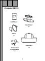
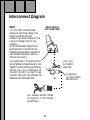
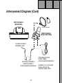
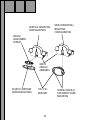
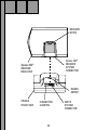
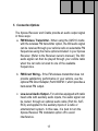
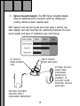
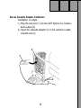
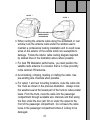
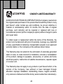
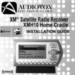
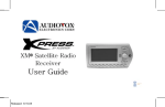
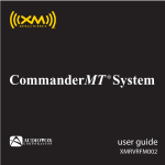
Table of Contents
Congratulations .......................................................................... 3
FCC Information ........................................................................ 4
Cautions and Warnings ............................................................. 5
Contents XMC10 ........................................................................ 6
Accessory Kit .......................................................................... 7
Installation/Wiring Precautions .................................................. 8
Setting Up and Installing Your Kit .............................................. 9
Cabling Interconnections ........................................................ 9
Installing the Cradle Mount Base Assembly .......................... 9
Interconnect Diagram ............................................................... 10
Using Other Manufacturer’s Mounts .................................... 15
Installing the Xpress XM® Into the Cradle ............................ 15
Connection Options ............................................................. 17
Installation Guidelines ......................................................... 20
Warranty ................................................................................... 26
2
Congratulations
Thank you for purchasing the Audiovox Xpress XM® Satellite Car Kit. You
are one step closer to experiencing the latest innovation in XM® Satellite
Radio. XM® Satellite Radio will revolutionize your vehicle or in-home
entertainment.
XM® features over 170 digital channels — the most commercial-free
music, over 30 channels of news, sports, talk and entertainment, over 20
dedicated channels of XM® Instant Traffic & Weather, and the deepest
play-list in the industry with access to over 2 million titles!
XM® Satellite Radio service gives you the power to choose what you
want to hear - wherever and whenever you want it. XM® is America’s #1
Satellite Radio provider with over 4 million customers.
Your Audiovox Xpress XM® receiver must be used with an accessory kit,
such as the Audiovox Home Kit, Boom Box or Vehicle Kit as required by
your specific installation needs. These kits are available at retailers where
Audiovox main units are sold.
Required subscription for service sold separately.
Installation costs and other fees and taxes may apply, including a
one-time activation fee. All fees and programming subject to change.
College sports games subject to availability. Subscriptions subject to
Customer Agreement included with the XM Welcome Kit and available at
www.xmradio.com. Only available in the 48 contiguous United States.
© 2005 XM® Satellite Radio Inc. XM® is a trademark of XM® Satellite
Radio. All rights reserved. All other trademarks are the property of their
respective owners.
3
FCC Information
· NOTE: This equipment has been tested and found to comply with the limits for
a Class B digital device, pursuant to Part 15 of the FCC Rules. These limits are
designed to provide reasonable protection against harmful interference in a
residential installation. This equipment generates, uses and can radiate radio
frequency energy and, if not installed and used in accordance with the
instructions, may cause harmful interference to radio communications. However,
there is no guarantee that interference will not occur in a particular installation. If
this equipment does cause harmful interference to radio or television reception,
which can be determined by turning the equipment off and on, the user is
encouraged to try to correct the interference by one or more of the following
measures:
— Reorient or relocate the receiving antenna.
— Increase the separation between the equipment and receiver.
— Connect the equipment into an outlet on a circuit different from that to which
the receiver is connected.
— Consult the dealer or an experienced radio/TV technician for help.
This device complies with Part 15 of the FCC Rules. Operation is subject to the
following two conditions: (1) This device may not cause harmful interference, and
(2) this device must accept any interference received, including interference that
may cause undesired operation.
The user is cautioned that changes or modifications not expressly approved by XM®
Satellite Radio, Inc. can void the user’s authority to operate this device.
Please note that the cables that have been supplied with your XMC10 car cradle
are supplied with permanently attached ferrite beads. It is the responsibility of
the user to use the cable with the ferrite beads.
By adhering to these warnings and safety considerations, stated in the manual and
by XM®, accidents.
4
Cautions and Warnings
1. Do not install the XMC10 car cradle in a position that hinders your
view through the windshield, or obstructs viewing of the
dashboard indicators and displays.
2. Do not install the unit where it may obstruct the operation or
deployment of safety devices, such as airbags, etc.
3. Do not allow operation of the unit to detract from safe driving
practices; remember that you are responsible as the vehicle
operator to adhere to all safe driving and traffic regulations.
4. By adhering to these warnings and safety considerations,serious
accidents and/or personal injury can be avoided.
5
Contents XMC10
Install Manual
Swivel Bracket
1 pc.
Antenna
1 pc.
Cradle XMC10
1 pc.
12 Volt-to-5 Volt
DC Power Adapter
1 pc.
6
Contents XMC10 (Cont)
OPTIONAL
Audio Cable
(P/N SAT-RCA)
CLA Female Socket
1 pc.
Cassette Adapter
1pc.
ACCESSORY KIT
Alcohol Cleaning Pad,
Surface Cleaning Pad,
Instruction Sheet,
Antenna Cable Exit Plug
FM Direct Adapter
(P/N XMFM-1)
7
Installation/Wiring Precautions
1. To prevent a short-circuit, be sure to turn off the ignition and remove
the negative (-) battery cable prior to installation. Connect power
wires last.
2. Do not install the unit in the locations exposed to direct sunlight or,
in areas subject to extreme temperatures.
3. Incorrect installation may cause damage to the system. Mount
the unit firmly in place, using the supplied hardware.
4. Be careful not to damage the vehicle wiring.
5. Be sure to use the supplied screws and washers.
6. Be careful not to snag any wires when tightening screws.
7. Use only the 12 Volt-to-5 Volt DC Power Adapter supplied. Use of an
alternative power adapter may damage the Xpress XM® unit and/or
the XMC10 cradle.
CAUTION: You could drain the vehicle battery if the DC power
adapter remains plugged in after the ignition is turned
off. Unplug the adapter to prevent this possibility.
8
Setting Up and Installing Your Kit
NOTE: The XM signal can be received and processed virtually
anywhere as long as there are no obvious satellite signal
obstructions such as nearby buildings, high terrain, parking
garages or tunnels.
1. Cabling Interconnections
You can begin to enjoy XM® Satellite Radio as soon as the Xpress
XM® Receiver and Vehicle Kit installation are complete. Set up
your Audiovox Xpress XM® System using the following installation
instructions, or enlist the help of a professional installer:
2. Installing the Cradle Mount Base Assembly
a. Interconnect all of the components as shown on the adjacent
page to verify that the system operates normally.
b. Locate a firm, reasonably flat surface within your car to permit
optimum viewing and line-of-sight access by the supplied remote
control unit.
9
Interconnect Diagram
NOTE:
1. IF THE XMC10 IS INSTALLED
USING THE OPTIONAL XMFM-1 FM
DIRECT ADAPTER, DO NOT
CONNECT AN AUDIO CABLE TO THE
LINE OUT CONNECTOR OF THE
CRADLE.
2. THE FM TRANSMITTER OPTION
MUST BE SET TO ”FM ON” IN THE
XPRESS XM USER MENU. (REFER TO
THE OWNER’S MANUAL, PUBLICATION NO.128-7454C.)
XMC10 CRADLE
(LEFT SIDE VIEW)
AUX AUDIO INPUT TO AUDIO OUTPUT
OF EXTERNAL PLAYBACK DEVICE. THIS
PERMITS AUDIO FROM AN EXTERNAL
DEVICE SUCH AS A PORTABLE CD
PLAYER OR MP3 PLAYER TO BE
PLAYED THROUGH THE XPRESS XM
WIRELESS FM TRANSMITTER.
+12V to +5V
DC POWER
ADAPTER
OR
CLA FEMALE SOCKET WIRES
TO VEHICLE +12 VDC POWER
RECEPTACLE
10
TO VEHICLE
+12 VDC POWER
RECEPTACLE
Interconnect Diagram (Cont)
XMC10 CRADLE
(REAR VIEW)
XM ANTENNA
XMC10 CRADLE
(RIGHT SIDE VIEW)
TO VEHICLE RADIO
ANTENNA JACK
OPTIONAL FM DIRECT
ADAPTER XMFM-1
(PURCHASED SEPARATELY)
11
OPTIONAL SAT-RCA
AUDIO CABLE
(PURCHASED SEPARATELY)
(CONNECT TO AUXILIARY
AUDIO INPUTS ON
VEHICLE HEAD UNIT.)
CAUTION:
Do not install the swivel bracket on a leather or
fabric surface, or in a position that could impair
your vision, block air bag(s) or obstruct vehicle
dashboard controls and/or radio CD/cassette
operational displays.
NOTE: The adhesive backing on the bracket will not permit
easy repositioning once it has been mated to the
surface; use extreme care and planning when
selecting the mounting location. If the bracket is to be
screwed to the surface, make sure the area in back of
the mounting surface is clear of wires or other items to
prevent unintentional damage.
c. Using the alcohol swab supplied with your kit, clean the mounting
surface and thoroughly wipe the area dry with a clean lint-free
cloth.
d. If the outside air temperature is cold, it may be beneficial to
warm the adhesive backing on the bracket using a portable hair
dryer, or by holding the backing surface in front of a vehicle
heater vent.
12
e.
Remove the plastic liner from the adhesive backing on the
bracket, and fix the base in position on the surface; make sure
the mounting pad is accurately positioned on the first try, since
repositioning may be difficult, if not impossible.
f.
If the bracket is to be screwed in place, do not remove the plastic
liner from the adhesive backing. Use appropriate sheet metal
or machine screws for this purpose.
g.
To mount the XMC10 cradle atop the swivel bracket, line up
the slot at the rear of the cradle with the bracket retainer tab,
and slide the cradle down so that the slot and tab mesh together
in a locked position.
NOTE: Allow a 72-hour period for the adhesive backing to cure
completely.
13
VERTICAL MOUNTING
CONFIGURATION
SIDE (HORIZONTAL)
MOUNTING
CONFIGURATION
SWIVEL
ADJUSTMENT
SCREW
XMC10
CRADLE
ASSEMBLY
PLASTIC LINER AND
ADHESIVE BACKING
SWIVEL
BRACKET
14
SCREW HOLES (2)
FOR DIRECT HARD
MOUNTING
3. Using Other Manufacturer’s Mounts
The XMC10 Cradle can also be installed using other manufacturer’s
mounts; the mounting plate provisions on the rear and bottom of
thecradle provide you with two mounting options within the vehicle
using various vehicle-specific aftermarket brackets.
4. Installing the Xpress XM® Receiver into the Cradle
Install the Receiver as follows:
a. After making sure the connectors and guide pin hole are properly
lined up, gently lower the Xpress XM® Receiver into the cradle
and press down on the Xpress XM® Receiver to mate the
connectors together. The raised detent on the cradle will enter
the notch on the rear of the Receiver, indicating the Xpress XM®
is properly seated.
b. The Xpress XM® Receiver should now be secured in the
cradle
15
RECEIVER
NOTCH
Xpress XM®
RECEIVER
SYSTEM
CONNECTOR
Xpress XM®
RECEIVER
REAR VIEW
RAISED
DETENT
CRADLE
FRONT VIEW
CONNECTOR
GUIDE PIN
16
XMC10
SYSTEM
CONNECTOR
5. Connection Options
The Xpress Receiver and Cradle provide an audio output signal
in three ways:
a. FM Wireless Transmitter - When using the XMC10 cradle
with the wireless FM transmitter option, the XM audio signal
can be received through your vehicle radio on selectable FM
frequencies using the menu options included in your Xpress
Receiver. (Refer to the Receiver owner’s manual.) The XM
audio signal can then be played through your vehicle radio
when the car radio is tuned to one of the available
frequencies.
b. FM Direct Wiring - If the FM wireless transmitter does not
provide satisfactory performance in your vehicle, use the
optional FM Direct Adapter, Part # XMFM-1, which provides a
hard-wired FM output.
c. Low-Level Audio Output - For vehicles equipped with radio
head units with auxiliary audio inputs, the audio signal can
be routed through an optional audio cable (Part No. SATRCA) and applied to the auxiliary inputs of a radio or
entertainment system. In this case, it is best to turn the
Xpress Receiver FM modulator option off to avoid
interference.
17
d.
Xpress Cassette Adapter -The XM7 Xpress Cassette Adapter
offers an additional audio connection option by utilizing your
existing vehicles in-dash cassette deck.
XM7 research and lab test results show that using a vehicle cassette adapter can best maximize the relationship between the best
sound quality and ease of installation (see chart below).
XMC10 CRADLE
(RIGHT SIDE VIEW)
TO VEHICLE
RADIO ANTENNA
JACK
OPTIONAL SAT-RCA
AUDIO CABLE
(PURCHASED
SEPARATELY)
(CONNECT TO
AUXILIARY AUDIO
INPUTSON VEHICLE
HEAD UNIT.)
OPTIONAL FM DIRECT
ADAPTER XMFM-1
(PURCHASED SEPARATELY)
18
Xpress Cassette Adapter Installation.
Installation is simple.
1.) Plug the end jack (1) into the XM7 Xpress Car Cradle’s
audio output (2).
2.) Insert the cassette adapter (3) in the vehicles in-dash
cassette slot (4).
4
3
2
1
19
6. Installation Guidelines
IMPORTANT: For best wireless FM Modulator performance, you
must locate the satellite radio antenna in a location
that is in close proximity to the vehicle’s FM
antenna.
For example, with reference to the adjacent illustration, if your FM
antenna is located on a rear fender or top of the roof, mount the
XM antenna near the rear window location (option 1). If your FM
antenna is located on a front fender, mount the XM antenna near
the windshield location (option 2). Remember, the closer the
satellite radio antenna can be to the FM antenna, the better the
wireless FM reception and sound quality will be. In order to
optimize the operation of the wireless FM modulator, follow the
installation guidelines outlined in steps 1 through 4 as follows:
Step 1.
First, determine the proper location for your satellite radio antenna
based on the following criteria for your specific vehicle:
a. You must locate the satellite radio antenna on the top of the
roof either in front of the rear window (option 1) or behind the
windshield (option 2). The satellite radio antenna will perform
best if magnetically attached to a steel surface with an
unobstructed view of the open sky and minimum of 3 to 6
inches of metal surrounding the antenna.
20
OPTION 1
OPTION 2
KEEP EXCESS CABLE
UNDER OR BEHIND
THE DASHBOARD
b. When routing the antenna cable along the windshield or rear
window, tuck the antenna cable under the window seal to
maintain a professional looking installation and to avoid loose
wires on the exterior of the vehicle which are susceptible to
damage. Follow the interior cable routing diagram depicted
by dashed lines in the illustration above where possible.
c. For best FM Modulator performance, you must position the
satellite radio antenna in a location that is in close proximity
to the vehicle’s FM antenna.
d. Avoid kinking, crimping, twisting or chafing the cable. Use
pre-existing wire channels when possible.
e. For option 1 and rear mounting locations, route the cable into
the trunk as shown in the previous illustration. Always cross
the weather seal at the lowest part of the trunk to reduce water
leaks. From the trunk, route the cable into the passenger
compartment through available wire channels and then along
the floor under the door jam trim or under the carpet to the
front of the passenger compartment. Do not leave the cable
loose in the passenger compartment where it is likely to be
damaged.
21
f. For option 2 and front mounting locations, route the cable
along the door jam and into the vehicle as shown. Route the
cable across the weather seal near the bottom of the door to
reduce water leaks.
Step 2.
Be sure to locate your car cradle and receiver below the top of the
dash in your vehicle to keep the product within easy reach while
driving. Choosing a lower location in your installation should also
make it easier to manage the cables and achieve a more desirable
appearance when the installation is completed. A lower location for
the receiver in the vehicle will ensure that the installation does not
cause interference with other FM radios outside the vehicle. See
illustration below and be sure to locate your car cradle within the
outlined shaded areas.
22
Step 3.
Once you have plugged the
power and antenna jacks
into the car cradle, use the
included cable organizer as
shown in the illustration at
right to improve the overall
appearance of the
installation.
Step 4.
Re-use the cable twist ties
that were provided with the
power adapter and car
antenna cables and always
be sure to gather, bundle,
twist-tie, and secure any
excess cable remaining
after determining the best
location for your satellite
radio intallation.
23
For example, secure the excess cable up under your dash board,
between the seat and the console, or on the floor under a seat or
floor mat. This will help to prevent the excess cable from interfer
ing with the everyday use of your vehicle, improve the appearance
of the installation, and avoid any undesirable accidental damage
to the cables that might result in loss of power or satellite signal.
For wireless FM modulator installations, securing and tie-wrapping
the excess cable is important to reduce background hissing noise.
Be sure to choose a location carefully by taking notice of how
doors and trunks open and close, as well as how seats move
when they are adjusted so you can be certain there is ample
clearance provided for the cables.
24
NOTES
25
12 MONTH LIMITED WARRANTY
AUDIOVOX ELECTRONICS CORPORATION (the Company) warrants to
the original retail purchaser of this product that should this product or any
part thereof, under normal use and conditions, be proven defective in
material or workmanship within 12 months from the date of original
purchase, such defect(s) will be repaired or replaced with new or
reconditioned product (at the Company's option) without charge for parts
and repair labor.
To obtain repair or replacement within the terms of this Warranty, the
product is to be delivered with proof of warranty coverage (e.g. dated bill
of sale), specification of defect(s), transportation prepaid, to an approved
warranty station or the Company at the address shown below.
This Warranty does not extend to the elimination of externally generated
static or noise, to costs incurred for installation, removal or reinstallation
of the product, damage to speakers, accessories, or vehicle and home
electrical systems, malfunction of satellite transmissions, repeater signal
or receiver unit.
This Warranty does not apply to any product or part thereof which, in the
opinion of the Company, has suffered or been damaged through
alteration, improper installation, mishandling, misuse, neglect, accident,
or by removal or defacement of the factory serial number/bar code label(s).
26
THE EXTENT OF THE COMPANY'S LIABILITY UNDER THIS WARRANTY
IS LIMITED TO THE REPAIR OR REPLACEMENT PROVIDED ABOVE
AND, IN NO EVENT, SHALL THE COMPANY'S LIABILITY EXCEED THE
PURCHASE PRICE PAID BY PURCHASER FOR THE PRODUCT.
This Warranty is in lieu of all other express warranties or liabilities. ANY
IMPLIED WARRANTIES, INCLUDING ANY IMPLIED WARRANTY OF
MERCHANTABILITY, SHALL BE LIMITED TO THE DURATION OF
THIS WRITTEN WARRANTY. ANY ACTION FOR BREACH OF ANY
WARRANTY HEREUNDER INCLUDING ANY IMPLIED WARRANTY
OF MERCHANTABILITY MUST BE BROUGHT WITHIN A PERIOD
OF 48 MONTHS FROM DATE OF ORIGINAL PURCHASE. IN NO
CASE SHALL THE COMPANY BE LIABLE FOR ANY CONSEQUENTIAL OR INCIDENTAL DAMAGES FOR BREACH OF THIS OR ANY
OTHER WARRANTY, EXPRESS OR IMPLIED, WHATSOEVER. No
person or representative is authorized to assume for the Company any
liability other than expressed herein in connection with the sale of this
product.
Some states do not allow limitations on how long an implied warranty
lasts or the exclusion or limitation of incidental or consequential damage
so the above limitations or exclusions may not apply to you. This
Warranty gives you specific legal rights and you may also have other
rights which vary from state to state.
U.S.A. : AUDIOVOX ELECTRONICS CORPORATION, 150 MARCUS BLVD.,
HAUPPAUGE, NEW YORK 11788 (1-800-645-4994)
128-7351
27
© 2006 Audiovox Electronics Corporation
128-7472D