1
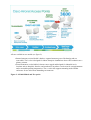
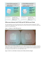
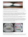
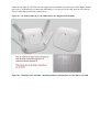
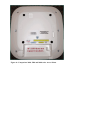
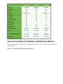
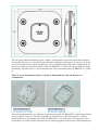
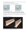
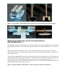
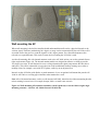
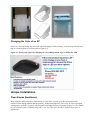
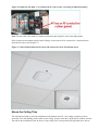
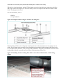
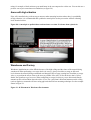
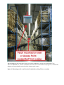
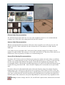
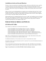
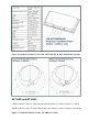
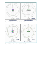
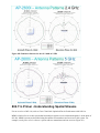
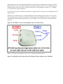
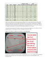
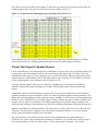
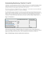
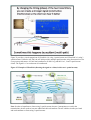
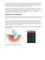
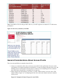
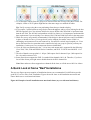
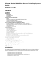
Aironet Series 2600/3600 Access Point Deployment
Guide
Document ID: 113684
Contents
Introduction
Prerequisites
Requirements
Components Used
Conventions
Choosing the Correct Access Point
Models
Differences between the AP 3600 and AP 3500 Access Points
AP 3600 Feature Module Support
Differences between the AP 3600 and AP 2600
Access Point Physical Hardware and Mounting Options
Channel Rail Adapters − Cisco Part Number AIR−CHNL−ADAPTER
Mounting an AP Directly into the Tile Using Optional AIR−AP−BRACKET−3
Wall mounting the AP
Changing the Color of an AP
Unique Installations
Clean Rooms (Healthcare)
Above the Ceiling Tiles
Stadium / Harsh Environments
Areas with high vibration
Warehouse and Factory
Installations in IDF Closets (Telecommunications or other Electrical Equipment)
Installations at Very High Altitudes
Installations Using a Common or Distributed Antenna System (DAS)
Installations Inside and Around Elevators
External Antenna Options and Patterns
AP 2600 and AP 3600e
AP 3600i and AP 2600i
802.11n Primer −Understanding Spatial Streams
Clients That Support 3 Spatial Streams
Understanding Beamforming ClientLink 1.0 and 2.0
Site Survey Considerations
General Considerations About Access Points
A Quick Look at Some "Bad"Installations
Related Information
Introduction
This document provides information about the Cisco 2600 and 3600 Series Access Points (APs) theory of
operation and installation as part of a Cisco wireless LAN (WLAN) solution. Subjects related include:
• Differences between AP 3600 and AP 3500
• Differences between AP 2600 and AP 3600
• Hardware details (including explanation of extra slot for future use)
• Mounting options, bracket choices
• Antenna options and radiation patterns
• Spatial streams, MCS rates, and what they mean
• ClientLink 2.0 what this means for Bring Your Own Device (BYOD)
• Site Survey considerations
This document is intended for trained and experienced technical personnel familiar with the existing Cisco
Wireless Networking Business Unit (WNBU) product line and features.
Prerequisites
Requirements
There are no specific requirements for this document.
Components Used
This document is not restricted to specific software and hardware versions.
The information in this document was created from the devices in a specific lab environment. All of the
devices used in this document started with a cleared (default) configuration. If your network is live, make sure
that you understand the potential impact of any command.
Conventions
Refer to Cisco Technical Tips Conventions for more information on document conventions.
Choosing the Correct Access Point
Models
The Cisco 3600 Series Access Point (AP 3600) targets customers requiring support for mission−critical
applications. The AP 3600 embodies ClientLink 2.0, an innovative antenna technology comprised of four
transmit radios and four receive radios called 4x4 Multiple Input Multiple Output (MIMO) and three spatial
stream (3SS) beamforming, together referenced as 4x4:3. ClientLink 2.0 permits speeds up to 450 Mbps via
additional Modulation and Coding Scheme (MCS) data rates 16−23, while still maintaining IEEE 802.3af
(15.4 Watt) Power over Ethernet (PoE) compliance. More on spatial streams can be found in the 802.11n
Primer Understanding Spatial Streams section of this document.
Figure 1 Access Point Portfolio Placement
APs are available in two models (see figure 2):
• Internal antennas version labeled i that have captured antennas (part of the housing and not
removable). The i series is designed for indoor Enterprise installations where office aesthetics are a
primary concern.
• External antennas version labeled e that are more rugged and designed for industrial use in
locations such as hospitals, factories, and warehouses, anywhere a need exists for external antennas
and/or extended operating temperatures. The e version also supports mounting inside NEMA
enclosures for use in the most demanding environments.
Figure 2 AP 3600 Models and Eco−packs
Differences between the AP 3600 and AP 3500 Access Points
The internal antenna version of AP 3600 and AP 3500 is almost identical in physical appearance with the
exception of the LED which is slightly larger and more oval on the AP 3600. The AP 3500 has a square LED
(allows for visual identification).
Figure 3 AP 3600vs AP 3500 LED Appearance
From a side view, the AP 3600 is slightly thicker when compared to the AP 3500. The thicker size allows for
additional radio support and printed circuit board area, as well as modularity for future capabilities. While the
AP 3600 has a little more depth, this AP is completely backward compatible with the mounting brackets for
the existing Cisco Aironet 1040, 1140, 1260 and 3500 Series APs.
Figure 4 Side View of AP 3600 (2.11 inches) and AP 3500 (1.84 inches) in height
The AP 3600e (external antenna version) differs in appearance from the AP 3500e, having fewer antenna
connector ports primarily due to the dual−band antenna systemthat is used.
The AP 3500e has separate antennas for each band, 2.4 GHz and 5 GHz, and does not support 3SS technology
because it has only two transceivers and one receiver per band (2SS).
The AP 3600e has combined all the antenna ports (dual−band) so that each antenna port can transmit
simultaneously on each band. If the antenna ports are not combined, 8 antennas are required. The AP 3600 has
four transceiver (transmitter/receiver) radio ports per band for a total of eight transceivers, four in each band.
This additional radio per band permits beamforming to 3SS clients using ClientLink 2.0. This improves the
overall performance of all 802.11n clients with 1, 2 and 3 spatial streams.
Note: Beamforming to a 3SS client requires n+1 RF design. In order to accomplish this, the AP 3600 has an
additional radio per band, which improves client performance by using Cisco ClientLink 2.0.
The newer AP 3600 design supports an additional feature module. The bottom of the AP 3600 unit looks
different as it has openings to support the feature module. The openings, while fully sealed, permit the module
to have access to the topside of the AP to allow the module antennas (if present in the module being used) to
fully function. The unit includes a positive snap spring loaded BB so the installer can feel a positive lock
when the AP is fully engaged in the bracket (see figure 5).
AP 3600 Feature Module Support
The feature module adds new functionalty to the AP to future−proof customers' investment. The first available
module provides a dedicated monitor module to scan the full spectrum (not just the channel on which the AP
is operating). It offloads complete monitoring and security services to the monitor module including
CleanAIr, WIDS/WIPS, Context−aware Location, Rogue Detection, and Radio Resource Management
(RRM). This module allows for full spectrum analysis on all channels on both the 2.4 and 5 GHz bands.
Having the add−on feature module avoids having to deploy a separate, dedicated overlay network for full
spectrum monitoring and eliminates the need for an extra cable pull and additional infrastructure costs (Figure
6).
The second available module provides 802.11ac (wave−1) functionality to the AP 3600. This radio module
operates at 5GHz and allows the AP 3600 to fully support 802.11a/n and 802.11ac clients. (Wave−1)
functionality supports a 1.3 Gbps PHY / ~1 Gbps MAC (throughput) using 3 spatial streams, 80 MHz, 256
QAM. Supporting Explicit Beamforming support the 802.11ac standard.
Use of the module might require the local power supply, Cisco power injector, .3at PoE+ or the use of Cisco
Enhanced PoE because the module can increase power draw greater then 15.4W.
Note: Cisco Enhanced PoE was created by Cisco and is the forerunner to 802.3at PoE+.
Figure 6 Feature Module Slides into Bottom of AP 3600
Differences between the AP 3600 and AP 2600
The AP 3600 has a modular design that offers future protection with the .11ac module, security module and
perhaps other modules in the future. The AP 3600 is a 4X4:3SS, which supports an extra transmitter chain for
additional downlink performance for all bands and clients.
The AP 2600 is similar to the AP 3600, but is a 3X4:3SS so with the AP 2600, Client Link does not
beamform to 3−ss clients. However; it does beamform at legacy and 1 and 2 Spatial Stream rates.
The AP 3600 has slightly higher performance and beamforms to legacy, 1, 2, 3 spatial stream rates and .11ac
rates when using the optional .11ac module.
Unlike the AP 3600, the AP 2600 does not support optional modules, but it does have a little higher antenna
gain in the 2.4 GHz band. For rounded out performance if you surveyed for the AP 3600, the AP 2600 can
also be used without performing another survey.
Figure 6a − AP 2600 is same size as AP 3600 but does not support radio modules
Figure 6b − Backside of the AP 2600 − mounting hardware and antennas are the same as AP 3600
Figure 6c Comparison 3600, 3500 and 2600 series Access Points
Access Point Physical Hardware and Mounting Options
Both the AP 2600 and AP 3600 have the same physical characteristics presented in the mechanical drawing
shown in figure 7.
Figure 7 AP 2600 and AP 3600 Mechanical Drawing
There are many different installation options available, which depends on customer requirements. Brackets
are available from Cisco as well as third−party companies. During the ordering process, make sure to choose
one of two brackets (but not both). Each bracket is a zero−dollar ($0) option at the time of configuration. If a
bracket is not chosen, the selection default is AIR−AP−BRACKET−1, which is the most popular for ceiling
installations. The other choice is a universal bracket that carries part number AIR−AP−BRACKET−2 (figure
8).
Figure 8 Access Point Bracket Choices If using AP 3600 module the AIR−AP−Bracket−2 is
recommended
If the AP is mounted directly to a ceiling on the gridwork, then AIR−AP−BRACKET−1 mounts flush and has
the lowest profile. However, if the AP is mounted to an electrical box or other wiring fixture, or inside a
NEMA enclosure or wall mounted, then AIR−AP−BRACKET−2 is a better choice. The extra space in the
bracket allows for wiring, and the extra holes line up with many popular electrical boxes. When mounting the
bracket to the ceiling gridwork, some ceiling tiles are recessed. For this reason, two different styles of ceiling
clips, recessed and flush rails, are available (Figure 9).
Figure 9 Different clips are available for attaching to ceiling gridwork.
Channel Rail Adapters − Cisco Part Number AIR−CHNL−ADAPTER
When mounting APs to ceiling channel rails such as the ones shown in figure 10, an optional channel adapter
is used: AIR−CHNL−ADAPTER. It comes in a two−pack and attaches to the ceiling grid clip above. See
figures 11 and 12.
Figure 10 Example of Channel Rails
Figure 11 AIR−CHNL−ADAPTER (left) Slides onto the Rails
Figure 12 AIR−CHNL−ADAPTER Mounted to Rail Clip (left) and Finished Installation (right)
Mounting an AP Directly into the Tile Using Optional
AIR−AP−BRACKET−3
Many hospitals and other carpeted Enterprise environments prefer a more streamlined look and wish to install
the AP directly into the tile. This can be done using the optional Cisco AIR−AP−BRACKET−3 (see figure
13).
When using this bracket, the beauty ring is used as the template to cut the tile which can be cut using a
carpet knife or electric tool such as a rotary cutting tool, for example, Dremel® or Rotozip®. Cisco does not
offer custom cut tiles.
The AP is fully supported above the tile with a metal rail that extends the length of the tile. This supports the
AP should the tile become wet or otherwise fail. A mechanical set screw pulls the AP tight to the ceiling and
locks it into the bracket. Additionally, physical security of the AP can be maintained by the use of a
Kensington style lock, but once installed it is difficult to remove the AP without removing the tile as the AP
will not slide out from the front side of the tile.
Figure 13 Optional AIR−AP−BRACKET−3 used to install the AP directly into the tile
Wall mounting the AP
When wall mounting is desired, the installer should understand that walls can be a physical obstacle to the
wireless signal. Therefore, maintaining 360−degree coverage can be compromised by the wall. If the wall is
an outside wall or the goal is to send the signal in a 180−degree pattern, use a directional antenna often
referred to as a patch antenna. This can be a better choice assuming the AP 3600e is used.
Avoid wall mounting APs with internal antennas, such as the AP 3600i, unless you use the optional Oberon
right−angle mount (Figure 14). The internal antenna model was designed to mount to a ceiling to provide
360−degree coverage. If wall mounted in a non−ceiling orientation the signal can penetrate the floor above
and below. This causes unintended coverage that can result in additional needless roaming access when a
mobility client, for example a user with Wi−Fi phone, walks by on an adjacent floor.
Instead, use the AP 3600e (with dipoles or patch antennas). Or, use an optional wall mount that puts the AP
3600i or AP 3500e on a ceiling type orientation when mounted to a wall.
Note: APs with internal antennas, such as a wall mounted AP 3600i, should use the Oberon mounting bracket
unless roaming is not an issue, for example, hotspot, kiosk, or small venue scenario.
Figure 14 Wall−mounting APs antennas should be vertical (up/down) or use the Oberon right−angle
mounting structure − ideal for AP−3600i. Oberon P/N 1029−00)
Changing the Color of an AP
If there is a desire to change the color of an AP which might void the warranty, consider using colored vinyl
tape or a colored plastic cover from Oberon (Figure 15).
Figure 15 Third−party option for changing AP color,adding custom Logo, or hiding the LED
Unique Installations
Clean Rooms (Healthcare)
Many hospitals and factories have requirements to wipe down or gently spray the environment with a
chemical (often diluted material that has cleaning / disinfectant properties). The Cisco AP 3600 is designed
with a purpose guild Wi−Fi chipset with Enterprise and industrial class components (Figure 16). This enables
the AP enclosure to have a Plenum rating and is vent−less. Therefore, the unit is ideal for these types of
applications.
Figure 16 Inside the AP 3600 − Cover Removed (no vents or fans, everything is industrial quality)
Note: The AP 2600 is also made of a similar construction and design for clean room deployments.
If the cleanroom environment requires metal ceilings or areas where tile is not practical, a metal enclosure
from Oberon can be used (Figure 17).
Figure 17 Oberon Metal Enclosure Protects and Secures the AP in Clean Room Areas
Above the Ceiling Tiles
The AP 2600 and 3600 are rated for installation in the Plenum area (UL−243). Many customers prefer to
locate the AP so that nothing can be visible on the ceiling. In some cases this is preferred for aesthetic reasons.
This allows the installation of the AP above a drop ceiling. This is also preferred in high theft areas, such as
classrooms or areas where policy dictates that nothing can be visible on the ceiling.
When this is a hard requirement, optional T−Bar hangar accessories from third−party companies such Erico
and Cooper can be used (Figure 18). The Erico Caddy 512a or the Cooper B−Line BA50a or similar T−Bar
Grid T−Bar hangars can be used.
For more information, refer to:
• ERICO
• Cooper Industries
Figure 18 Example of How to hang an AP above the ceiling tiles
Note: Installing APs above the ceiling tiles should only be done when mounting below the ceiling is not an
option. The tiles must not be conductive. Such installations can certainly degrade advanced RF features such
as voice and location. Therefore, verify coverage and performance. Always try to mount the AP as close to the
inside middle of the tile as possible, and avoid areas with obstructions (Figure 19).
Figure 19 Installing AP Above Ceiling Tiles: Pick an Area Clear of Obstructions, Avoid Ceiling
Clutter
Stadium / Harsh Environments
If you want to install the AP in harsh environments where it can be exposed to weather, such as sporting areas,
stadiums, open garden areas or warehouse freezers, consider using a NEMA type enclosure.
Note: Some APs are not certified for outdoor deployments in a NEMA enclosure. This varies around the
world; for example, some regulatory agencies permit AP outdoor NEMA enclosures if the AP is indoors, such
as a freezer or garden area, but prohibit its use outdoors. This seems to vary with regard to weather radar
compliance and often UNII−1 compliance etc. Check with your Cisco account team or the communications
regulatory agency that has jurisdiction in your part of the world.
Figure 20 Example of NEMA 16x14x8 Enclosure with pressure vent on bottom
Third−party sources for NEMA type enclosures include:
• Oberon Inc.
• TerraWave Solutions
When using a NEMA type enclosure, try to have the cables exit out of the bottom of the enclosure so that rain
and moisture do not run down the cable into the enclosure. Also, the color of the enclosure can affect the heat
rating; for example, a black enclosure gets much hotter in the sun compared to a white one. You can also use a
pressure vent to prevent moisture accumulation (see figure 20).
Areas with high vibration
If the AP is installed using a side arm type mount or other mounting locations where there is a probability
of high vibration, it is recommended that a padlock or metal pin be used to prevent the AP from vibrating
loose from the bracket.
Figure 20a A metal pin or padlock does not deteriorate over time. It is better than a plastic tie.
Warehouse and Factory
Warehouse installations are often difficult because of the high ceilings and the clutter of the material being
warehoused. When performing a coverage check (site survey), always check the coverage at full stock
levels because the material being warehoused can change the RF coverage creating loss of uniform coverage.
Also, try to position the APs as close to the users as possible. If the AP is 30 feet in the air, that is 30 feet
farther, the signal has to go, best case. When configuring coverage for aisles, try to use directional (Patch)
antennas on the wall and shoot down the aisles. Or, use low−gain Omni−directional antennas on the ceiling
(such as dipoles) or mount the AP lower using pipe and electrical box mounting techniques. See the example
shown in Figure 21.
Figure 21 AP Placement in Warehouse Environment
When mounting an AP at the end of a pipe or electrical conduit box, use the universal bracket Cisco
AIR−AP−BRACKET−2, because it will mate to the holes of most electrical boxes (Figure 22). Conduit and
adapters can be purchased at most electrical or home repair centers.
Figure 22 Mounting an AP to an Electrical Conduit Box (ceiling T−Bar or conduit)
Ethernet Cable Recommendation
The AP 3600 will work fine with CAT−5e for new cable installations. However, it is recommended that
customers use CAT6a. This is the cabling required by the 10GE standard.
Antenna Cable Recommendation
Whenever practical/possible, keep antenna cable runs as short as possible. Cisco offers low loss (LL) and
ultralow loss (ULL) cables, which have the same characteristics as Times Microwave LMR−400 and
LMR−600.
Cisco cables carry the part number AIR−CAB (Aironet Cable) and then a length. For example, a 20 foot
length of LL cable with RP−TNC connector is Cisco AIR−CAB−020LL−R. These heavy black cables are not
Plenum rated. These are primarily for outdoor use or manufacturing areas.
Access Point Spacing Recommendations
If you have a Wi−Fi device such as an AP and you are going to use another AP in the vicinity on a different
channel, it is recommended that you space each AP apart by approximately 6 Ft (2 meters). Avoid clustering
the APs or the antennas from different APs together, as this can cause degradation in performance. This
recommended distance is based on the assumption that both devices operate in the unlicensed band and do not
transmit RF energy more than 23 dB − that is, 200 mW. If higher power is used, make sure to space farther
apart.
If you have other devices that transmit and operate in the same frequency ranges, for example, frequency
hopping legacy APs or other devices that operate close in frequency to those of the AP (below or above the
2.4 and 5 GHz band), you should consider moving or separating the devices as far apart as can reasonably be
done. After you have done this, check for interference by testing both devices at the same time under heavy
utilization (load). Then, characterize each system independently to see how much, if any, degradation exists.
Warning: In order to comply with FCC, EU, and EFTA RF exposure limits, antennas must be located
at a minimum of 7.9 inches (20 cm) or more from the body of all persons. See the installation guide under
declaration of conformity for more on this.
Installations in IDF Closets (Telecommunications or other Electrical
Equipment)
When installing APs near other electrical or telecommunications equipment, keep all wiring and metal away
from the antennas and avoid placing the antennas near electrical lines. Do not route wiring electrical or
Ethernet in the near field (6−15 inches) from the antenna. Refrain from installing the AP in the electrical
closet, as the best place for the AP is as close to the users as possible. If you remote antenna cables from such
a closet, you might be required to use Plenum rated cable (see local fire/safety regulations for more on this).
Refer to these documents for more information about interference:
• 20 Myths of Wi−Fi Interference
• Wireless LAN Equipment in Medical Settings: Addressing Radio Interference Concerns
• Wireless RF Interference Customer Survey Results
Installations at Very High Altitudes
While not defined in the specification sheet for the AP 2600 and AP 3600, these Access Points passed
functional checks after a Non−Operational altitude test of 25C at 15,000 feet was performed. Additionally,
they fully passed a functional test during an operational altitude test of 40C at 9,843 feet.
All units in the test group were connected to at least one WLAN client and monitored for continual operation
passing traffic, and performed constant ping testing throughout the operational altitude test.
Installations Using a Common or Distributed Antenna System (DAS)
Due to the dual−band nature of the antenna system on the AP 2600 and AP 3600, and key features such as
ClientLink 2.0 beamforming, it is not recommended for deployments on Distributed Antenna Systems
commonly referred to as DAS.
Customers wishing to integrate a Wi−Fi over DAS solution should understand that Cisco does not certify,
endorse or provide RF support for Wi−Fi deployments over any Distributed Antenna System.
The DAS vendor and/or systems integrator is solely responsible for the support of the DAS products, and for
providing adequate RF coverage and supporting any RF−related issues. This support includes, but is not
exclusive to, location accuracy, RF coverage, roaming issues related to RF, multipath issues, and scalability.
Additionally, the DAS vendor and/or systems integrator is responsible for understanding that the deployed
DAS system meets the requirements of all of the customer's Wi−Fi devices and applications over the DAS
system. This statement includes, but is not exclusive to, all Voice over WLAN (VoWLAN) and medical
devices.
While Cisco Technical Assistance Center (TAC) and Cisco field teams do not provide support for RF issues
that occur in a Cisco WLAN used over a DAS, they will provide support for non−RF related issues in Cisco
products per the customer's support agreement with Cisco Systems.
For more information, refer to Positioning Statement on Cisco Wireless LAN over Distributed Antenna
Systems.
Installations Inside and Around Elevators
Elevator coverage can sometimes be accomplished by placing APs in the near field of the elevator, typically
on each floor near the elevator door. Because elevators often have metal doors and the shafts are often
concrete or contain other materials that degrade Wi−Fi coverage, it is important to check the coverage inside
the elevator. While such coverage can be challenging it is often do−able, especially if the elevator is only a
few floors.
High rise elevators are more challenging because roaming issues are problematic when the client is cycling
through a large number of APs quickly. Some companies that do in−elevator advertising have put a patch
antenna on the floor inside the shaft and a patch antenna on the bottom of the elevator car. Other companies
have used leaky coaxial cable running on the side of the shaft.
When installing any Wi−Fi equipment inside the elevator cars or shafts, local regulations need to be followed.
Many times such installations are prohibited either for safety reasons, or because the building owner or local
fire department can prohibit same. Also, it is dangerous and only elevator repair persons or contractors
experienced with this kind of work should be in those areas.
External Antenna Options and Patterns
AP 2600 and AP 3600e
These antennas are available for use with the AP 2600 and 3600e:
• AIR−ANT2524DB−R Dual−band (Black) dipole (4 required) 2/4 dBi Dipole
• AIR−ANT2524DW−R Dual−band (White) dipole (4 required) 2/4 dBi Dipole
• AIR−ANT2524DG−R Dual−band (Grey) dipole (4 required) 2/4 dBi Dipole
• AIR−ANT2524V4C−R Dual−band Omni−directional (1 required) 2/4 dBi Ceiling mount use
• AIR−ANT2544V4M−R Dual−band Omni−directional (1 required) 4/4 dBi Wall mount Omni use
• AIR−ANT2566P4W−R Dual band directional (1 required) 6 dBi Patch wall mount use
Note: These are all dual−band, dual−resonant antennas. Do not use single−band antennas on this product
unless you choose to disable the other radio band within the AP.
For additional information on Cisco antennas, refer to the Cisco Antenna Reference Guide.
The antenna reference guide has information for all Cisco antennas. You can also find individual datasheets at
Data Sheets and Literature.
The two most popular external antennas for the AP 3600e are the AIR−ANT2524Dx−R dual−band dipole
antenna (Figures 23 and 24) and the AIR−ANT2566P4W−R dual−band patch antenna (Figures 25 and 26).
Figure 23 Specifications for the AIR−ANT2524Dx−R Dual−band Dipole Antenna
Figure 24 Radiation Pattern for the AIR−ANT2524Dx−R Dual−band Dipole Antenna
Figure 25 Specifications for the AIR−ANT2566P4W−R Dual−band Patch Antenna
Figure 26 Radiation Pattern for the AIR−ANT2566P4W−R Dual−band Patch Antenna
AP 3600i and AP 2600i
Antenna patterns for the AP 3600i integrated antenna model are shown in Figures 27 and 28.
Antenna patterns for the AP 2600i integrated antenna model are shown in Figures 28a and 28b
Figure 27 Radiation Patterns for the AP−3600i at 2.4 GHz
Figure 28 Radiation Patterns for the AP−3600i at 5 GHz
Figure 28a Radiation Patterns for the AP−2600i at 2.4 GHz
Figure 28b Radiation Patterns for the AP−2600i at 5 GHz
802.11n Primer −Understanding Spatial Streams
For an overview of 802.11n, refer to Cisco ClientLink: Optimized Device Performance with 802.11n.
MIMO, which refers to a radio system that has multiple separate receive and transmit paths, is at the heart of
802.11n. MIMO systems are described using the number of transmitters and receivers in the system. For
example, two by one, or 2x1, refers to a system with two transmitters and one receiver (Figure 29).
Spatial streams, the act of transmitting information out of more than one antenna port concurrently, require
that the AP have at least two or more transmitters and support elements of 802.11n, for example, support of
multiple spatial streams. In the 802.11a/b/g days data rates were actual Mbps rates such as 2, 11, 54 Mbps
etc., and was done with one transmitter.
The AP 3500 series has two transmitters per band so it supports 802.11n data rates up to 300 Mbps using two
spatial streams.
With 802.11n the different rates are called Modulation and Coding Scheme (MCS) index value. The value
also defines how many streams are used. The AP 3500 supports up to 300 Mbps (MCS rate 15 configured
with a bonded channel and short guard interval (GI). See Figure 30. The MCS values correspond to actual
data rates.
Figure 29 AP 3500i/e is a 2x3:2 system (supports up to 2 transmit chains)
Note: 2x3:2 means two transmitters, three receivers supporting 2 spatial streams.
Figure 30 Modulation and Coding Scheme: 2SS Bonded Channel Supports up to 300 Mbps
Unlike the AP 3500, the newer AP 3600 supports 3SS with twice as many transmitters (4 per band). This
enables faster data rates of up to 450 Mbps. Note that there is an extra radio for redundancy and enhanced
performance (upstream and downstream). Also, the AP 3600 can beamform to 3SS clients as well. The AP
2600 is similar. However, the extra or redundant radio is for upstream because it is a receive only. Therefore,
it is unable to beamform to 3−ss clients but can beamform at the other non−3ss rates.
Using a dual−band design the AP 3600 has a total of 8 transceivers (transmitter/receivers) that use only four
antennas (Figure 31). Four radios are used in each band, 2.4 GHz and 5 GHz.
Figure 31 AP 3600: 4 Transmitters and 4 Receivers per Radio Band
The AP 2600 is similar to the AP 3600, but has a slight difference as it is a 3x4:3 meaning. The AP 2600 also
has four antennas to help on the receive (upstream signal), but it only uses three transmitters on the
downstream side.
The yellow sections of the MCS chart in figure 32 depict the faster data rates supported by the AP 3600. The
AP3600 supports 802.11a/b/g rates as well as 802.11n rates of MCS values 0−23.
Figure 32 AP 2600 and AP 3600 Supports up to 450 Mbps (MCS rates 0−23)
These additional MCS rates permit more choices for the client supporting 3SSwhen making rate−shifting
decisions because the rate−shifting algorithm maintains the best overall throughput connection.
Clients That Support 3 Spatial Streams
Clients with 3SS support are starting to become commonplace. As the new 802.11ac specification starts to get
traction, many newer client adapters will have the newer chipsets and support 3SS as a subset to 802.11ac.
Additionally, unlike many of Cisco's competitors, the Cisco AP 3600 and AP 2600 fully support all the DFS
channels for more usable channels in the 5 GHz range. More clients, especially 802.11ac clients, will start to
emerge supporting these newer channels in 802.11n modes as well.
Currently, the most popular 3SS client is the Apple 2011 MacBook Pro. It is based on the Broadcom
BCM4331 chipset and a small USB adapter by Trendnet, TEW 684UB, which is based on the Ralink
chipset.
Additionally, the Intel 5300 and 6300 have supported 3SS for a long time. Perhaps because of the different
hardware platforms this card is installed in, testers have observed good throughput on many notebooks (+320
Mbps) and reduced throughput on other notebooks, such as 240 Mbps. If you experience low throughput using
the Intel card, try a MacBook Pro or Trendnet adapter. If these perform well, then try another notebook with
the Intel card. Or, open a case with Intel or the laptop manufacturer for a possible remedy. During the AP
3600 beta trials, differences in performance were observed with different notebooks using the Intel 6300 card.
Note: It can be difficult to reliably maintain a 3SS link because it is easy for the client to rate−shift out of the
3SS mode. The client plays an important role in the ability to maintain a 3SS link, so it can vary with the
quality of the client being used and the test environment.
The AP 3600 with its extra radio per band can use the extra redundant radio to beamform (thanks to
ClientLink 2.0), and uses this to maintain the advantage of 3SS links. Cisco ClientLink 2.0 can also improve
the overall performance of 802.11n clients using 1, 2 and 3 spatial streams and legacy .11a/g clients.
Understanding Beamforming ClientLink 1.0 and 2.0
ClientLink 1.0 was first introduced with the AP 1250 and AP 1140 series. It is a method of creating a stronger
signal on the downlink side for 802.11a/g clients by hearing the clients on the uplink, then adjusting the
transmitter timing so the signal appears much stronger at the client end.
This feature used to be user configurable. However, starting with 7.2 code stream it is now on by default and
is not user configurable because there is no benefit to disabling it.
The AP 3600 fully supports ClientLink 1.0 for 802.11a/g clients but has a greater advantage because it also
supports all 802.11n clients including 1, 2 and 3 spatial stream clients. This capability is called ClientLink 2.0.
There is a distinct advantage with ClientLink 2.0 over the 802.11n enhanced beamforming specification.
ClientLink 2.0 works with all clients today and does not require any client sounding or support (Figure 33).
Figure 33 ClientLink 2.0
With beamforming technology, changing the timing of two transmitters creates a stronger signal for the
receiver, for example, a client device. This is referred to as constructive interference. Sometimes, the opposite
happens and the signals cancel each other out. This is called destructive interference. See figure 34.
Figure 34 Beamforming (constructive and destructive interference)
Figure 35 provides a visual comparison of ClientLink 1.0, using 1 spatial stream, and ClientLink 2.0, using 3
spatial streams. Unlike the AP 3500, the AP 3600 provides multiple spatial streams using four transceivers for
even greater performance. AP 3600 can beamform to all 802.11a/g and 802.11n 1, 2 and 3 spatial stream
clients. The signal is x3 as each stream is beamformed.
Figure 35 Example of ClientLink (directing the signal to a client, in this case 1 spatial stream)
Note: In order to beamform to clients using 3 spatial streams, because 3 transmitters are used in the
transmissions, the AP needs at least one additional radio to beamform. The AP 3600 has 4 radios pre−band
and can beamform to clients using 3 spatial streams.
In summary, ClientLink 2.0 takes the received signals heard from the client on the uplink, calculates how the
multipath signal looked from those streams, and then on the reciprocal side (transmit downlink) figures out
the optimal way using all four radios to best form the signal (transmit beamforming) to enable the client to
best decode (receive the signal on the downlink) with the least amount of retries.
ClientLink 2.0 enables beamforming to all 802.11n clients, including 3SS clients, and can do so for up to 128
clients at a time. ClientLink 1.0 supported a maximum of 15 clients at a time. ClientLink 2.0 significantly
improves throughput and coverage up to 60% on the downlink side for a much better 802.11n client
connectivity and enhancing the Bring Your Own Device (BYOD) experience. For more information on Cisco
ClientLink 2.0, refer to Cisco Wireless ClientLink 2.0 Technology.
Site Survey Considerations
While ClientLink dynamically beamforms and helps to maintain a robust signal which results in fewer retries,
it was not designed to change the cell range. ClientLink creates a better connection experience, not larger cell
size.
For this reason, when conducting a survey keep in mind that the AP 3600 cell sizes are generally the same or
similar to other Cisco APs. Figure 36 depicts typical ranges in the 1−54 Mbps range.While it is always
recommended to survey with the equipment you intend to deploy, a previous survey done with an AP 3500,
for example, would not be invalid for an AP 3600 deployment. Figures 37 and 38 provide examples of the
modulation types and signal−to−noise ratio (SNR).
Figure 36 AP 3600 Site Survey Ranges (typical cell sizes have not changed; AP 3500 and AP 3600 cell
sizes are the same)
Figure 37 Site Survey Sensitivity and SNR
Note: The WNR for 3SS is 28 dB, per IEEE. However, Cisco RF engineers recommend 30−32 dB for best
performance.
Figure 38 Site Survey Sensitivity and SNR
General Considerations About Access Points
These are some guidelines to remember about all APs:
1. Always try to mount the AP as close to the users as possible for best performance. Be aware of the
environment; for example, hospitals have metal doors, coverage can change when the doors close, old
buildings can have metal grid work in the plaster or asbestos. Avoid mounting the AP or antennas
near metal objects, because this can change the coverage area.
2. When using the 2.4 GHz frequency, the same 1, 6 and 11 channel scheme is used as is the 5 GHz
channel scheme (Figure 39). Avoid putting all of the APs on the same channel, and reuse channels
when you can.
Figure 39 Example of Channel Usage in 2.4 and 5 GHz
3. Try to determine which clients are going to be used and check the coverage using those clients. For
example, a PDA or Wi−Fi phone might not have the same range as a notebook or tablet.
Tip: Verify coverage using the worst performing clients that you intend to deploy.
4. If you require 3 spatial stream coverage for the fastest throughput, and/or you are looking for the best
BYOD experience, the Cisco Aironet 3600 Series Access Points with ClientLink 2.0 performs better
than the AP 3500. The AP 3600 can beamform to 802.11n clients, so it is important to understand the
data requirements if you are mixing Cisco Aironet 1260, 3500 and 3600 Series APs in the same areas.
5. While site surveys are generally recommended, if the design is done at half power and Cisco RRM is
in place, a limited site survey (coverage check) can be adequate for smaller venues. If this is a
challenging environment such as train connectivity, Gas and Oil verticals, large hospitals, etc. Cisco
has an Advanced Services team that can be contracted to help you get up to speed or perform your
installation. Contact your Cisco account team for more information.
6. Cisco AP 3600 was introduced in the 7.1.91 or later code stream and is supported by the following:
Cisco 2500, 7500, 5508 and WiSM2 Series Controllers, and WCS 7.0.220 or later and NCS 1.1 or
later.
7. The rule of thumb coverage plan is: 1 AP per 5,000 square feet for data and 1 per 3,000 square feet
for voice and location services.
8. Some clients do not support the UNII−2 extended client channels 100−140. Therefore, if you have
lots of older clients you might want to disable them in the DCA channel list.
Note: More and more clients support these channels all the time, as will the newer 802.11ac clients.
A Quick Look at Some "Bad"Installations
The next two figures present examples of installations that are not recommended. It is difficult to provide
good Wi−Fi service with a "bad" installation. Figures 40 and 41 show an AP installation near metal and
clutter. Make sure to avoid metal and clutter.
Figure 40 Example of an AP installation near metal and clutter (try to avoid metal and clutter)
Figure 41 Example of an AP installation near metal and clutter (try to avoid metal and clutter)
Tip: When mounting antennas outside, always mount with the wires down and never obstruct or put
weatherproofing material over the drain holes.
Figure 42 Always mount antennas outdoors with leads DOWN (indoors does not matter)
Related Information
• Cisco Aironet 3600 Series
• Wireless Products
• Cisco Aironet Antennas and Accessories Reference Guide
• Why Buy Cisco Antennas?
• Antenna Patterns and Their Meaning
• Deployment Guide: Cisco Guest Access Using the Cisco Wireless LAN Controller, Release 4.1
• Schools Wireless LAN Deployment Guide
• Wireless LAN Apple Bonjour Deployment Guide
• Optimizing Enterprise Video Over Wireless LAN
• Cisco Unified Wireless IP Phone 7925G, 7925G−EX, and 7926G Deployment Guide
• Cisco Mobility Services Engine − Context Aware Mobility Solution Deployment Guide
• Wireless LAN Design Guide for High Density Client Environments in Higher Education
• Technical Support & Documentation − Cisco Systems
Contacts & Feedback | Help | Site Map
© 2011 − 2012 Cisco Systems, Inc. All rights reserved. Terms & Conditions | Privacy Statement | Cookie Policy | Trademarks of
Cisco Systems, Inc.
Updated: Sep 07, 2012
Document ID: 113684