1
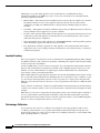
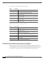
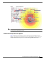
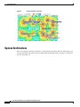
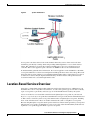
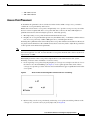
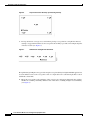
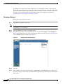
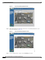
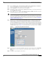
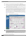
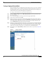
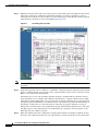
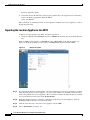
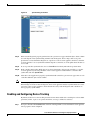
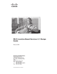
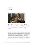
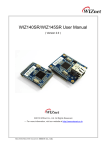
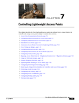
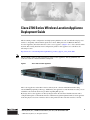
Cisco 2700 Series Wireless Location Appliance
Deployment Guide
This document provides configuration and deployment guidelines as well as troubleshooting tips and
answers to frequently asked technical questions for those adding the Cisco 2700 Series Wireless
Location Appliance (hereafter referred to as the location appliance) (Figure 1) to a Cisco wireless LAN
network. The existing installation and configuration guides for this appliance are available at the
following location:
http://www.cisco.com/en/US/products/ps6386/tsd_products_support_series_home.html
Note
This document assumes an indoor installation of the location appliance, and any guidelines and
accuracies cited are consistent with that assumption.
Figure 1
Cisco 2700 Location Appliance
The location appliance tracks 802.11 devices directly from a wireless LAN infrastructure using
advanced RF fingerprinting technology. Additionally, the appliance records information so that you can
establish location trends and resolve problems regarding RF capacity.
By design, the location appliance is directly integrated into the wireless LAN infrastructure and is
configured through its command-line interface and then managed through WCS. The location appliance
tracks the physical location of wireless devices using wireless LAN controllers and Cisco Aironet
Corporate Headquarters:
Cisco Systems, Inc., 170 West Tasman Drive, San Jose, CA 95134-1706 USA
© 2005 Cisco Systems, Inc. All rights reserved.
lightweight access points. This appliance tracks any Wi-Fi device, including Wi-Fi clients,
standards-based Wi-Fi active RFID tags, rogue access points, and clients. It was designed with the
following requirements in mind:
•
Manageability—The same browser-based interface that is used for the Cisco WCS is also used for
the appliance. Moreover, the location appliance integrates directly into the wireless LAN
architecture, providing one unified network to manage instead of multiple disparate wireless
networks.
•
Scalability —The appliance was built to simultaneously track up to 1500 wireless devices. WCS can
manage multiple location appliances for greater scalability.
•
Security—The controller, WCS, and the location appliance were separated to deliver the most secure
architecture possible. The appliance records historical location information that can be used for
audit trails and regulatory compliance.
•
Open and standards based—The appliance has a SOAP/XML API that can be integrated by partners
with other business applications and can track any standards.
•
Easy deployment of business applications—The appliance can be integrated with new business
applications such as asset tracking, inventory management, location-based security, or automated
workflow management.
Location Tracking
The location appliance calculates the location of tracked devices using RF fingerprinting. This technique
uses RF characteristics such as reflection, attenuation, and multi-path to impact signal strength readings
of devices in specific environments.
To detect the RF signal at each location in an enterprise, the system must first understand how the RF
interacts with an installation's environmental variables, such as building materials, walls, doors, and
furniture. As such, an RF calibration is required (post wireless LAN installation) to determine the
characteristics of that specific RF environment.
When an RF calibration is performed, the attenuation of walls and other building characteristics is taken
into account. The extent of RF reflection and multi-path is also calculated for every coordinate, or grid,
on a floor map in the management system for each access point. For a single point on the grid, many
different access points detect devices; however, each access point detects these devices at different signal
strengths.
At the conclusion of calibration, a database is populated inside of the management system. That database
contains each coordinate and how each access point views that coordinate from the standpoint of signal
strength.
When devices' locations are requested by the management system, each controller replies on behalf of
its access points with the signal strengths at which they detect them. The management system then
matches the information it gathers from the controllers against its database of location RF fingerprints.
Devices' locations are then plotted visually on a floor map.
Performing a Calibration
You can generate the location of coordinates of tracked devices by using prediction. The location
coordinates generated in this case are predicated from RF models that the engine already has in its
knowledge base. However, if the location resolution is not within specifications, it can be further tuned
using a technique known as calibration.
Cisco 2700 Series Wireless Location Appliance Deployment Guide
2
OL-8478-01
Calibration is the process whereby sample signal strength measurements are physically taken in the
actual environments in which you wish to perform location tracking as inputs to tune the location
tracking rather than using the canned or simulated environment’s inputs. Calibration is performed on a
per-floor basis with a wireless laptop using RSSI measurements.
The goal of the calibration process is to refine location accuracy to be within the specifications (10 m,
90%). The calibration is done by taking site specific measurements into account and narrowing the delta
between the actual and the predicted location coordinates of a tracked device. The calibration process is
complete when the actual and predicted location coordinates converge. On a per-floor basis, a wireless
laptop takes RSSI measurements. The calibration wizard, embedded in the WCS version of the product,
is launched from the laptop and guides the user through the calibration process.
Accuracy
Because location fidelity is statistical, the location coordinates can be either more or less accurate than
10 meters the other 10% of the time. The location coordinates that fall into this other 10% are known as
outliers. Making adjustments to the deployments of access points to provide more optimal placement, in
addition to performing a calibration, can sometimes yield more accurate results; however, the results are
very dependent on environment and deployment.
Software Requirements
Access points and controllers must be installed with a version of WCS using embedded location.
Table 1
WCS Versions
Part Number
Description
AIR-LOC-2700-L-K9
Cisco wireless location appliances
AIR-WCS-LL-1.0-K9
Cisco WCS with location v1.0 with up to 50
Cisco Aironet 1000 series access points running Linux
AIR-WCS-WL-1.0-K9
Cisco WCS with location v1.0 with up to 50 Cisco Aironet 1000
series access points running Windows 2000/2003 server
Expansion licenses are available if greater scale is necessary. Visit the following location for more WCS
SKUs:
http://wwwincisco.com/dsw/wnbu/products/wlm/cwcs/
Hardware Requirements
Because the location appliance participates in a Lightweight Access Point Protocols (LWAPP)
architecture, this guide assumes the user already has or is in process of putting an LWAPP- capable
wireless LAN in place. Both an explanation of the various LWAPP components you can use to do
location tracking as well as a hardware compatibility matrix is provided to ensure all required
LWAPP-compatible infrastructure is in place to support location tracking.
Cisco 2700 Series Wireless Location Appliance Deployment Guide
OL-8478-01
3
The following Cisco wireless LAN controllers are available.
Table 2
Controllers
Part Number
Description
AIR-WL C2006-K9
Cisco 2000 series wireless LAN controller for up to six Cisco
Aironet 1000 series lightweight access points
AIR-WL C4402-12-K9
4400 series WLAN controller for up to 12 Cisco Aironet 1000
series access points
AIR-WL C4402-25-K9
4400 series WLAN controller for up to 25 Cisco Aironet 1000
series access points
AIR-WL C4402-50-K9
4400 series WLAN controller for up to 50 Cisco Aironet 1000
series access points
AIR-WL C4404-100-K9
4400 series WLAN controller for up to 100 Cisco Aironet 1000
series access points
The following Cisco Aironet access points are available.
Table 3
Access Points
Part Number
Description
AIR-AP1010-X-K9
1000 series 802.11 a/b/g access point with integrated antennas,
x=regulatory domain
AIR-AP1020-X-K9
1000 series 802.11 a/b/g access point with integrated antenna
and RP-TNC, x=regulatory domain
AIR-AP1030-X-K9
1000 series 802.11 a/b/g remote edge access point with
integrated antenna and RP-TNC, x=regulatory domain
AIR-LAP1131AG-x-K9
802.11 a/g Non-modular LWAPP AP: Integrated Antennas
AIR-LAP1232AG-x-K9
AIR-AP1210 platform with AIR-MP21G and AIR-RM22A
radio modules
AIR-LAP1242AG-x-K9
802.11 a/g Non-modular LWAPP AP
The Difference Between WCS with Location and the Location Appliance
WCS without the use of the location appliance supports on-demand or query-based location. This
version visually displays a single device's location at a time, placing each single device on the floor map
associated with the floor it is on. Location determination using this version of WCS with location is
captured in Figure 2 where the blue icon is the only visual presented of a Wi-Fi client device.
Cisco 2700 Series Wireless Location Appliance Deployment Guide
4
OL-8478-01
Figure 2
Note
Location Determination
To add the location appliance, the WCS version with location must be installed. You cannot add the
location appliance to the WCS base version.
Additional Functionality with Location Appliance
Figure 3 illustrates the scale and variety of classes of devices that can be tracked by the location
appliance. You can narrow the search parameters if you are interested only in a subset of devices. For
example, a biomedical user may want to see only infusion pumps and EKG machines named with
friendly identifiers rather than rogue devices or devices with cryptic MAC or IP addresses.
Cisco 2700 Series Wireless Location Appliance Deployment Guide
OL-8478-01
5
System Architecture
Figure 3
Scale and Variety of Devices
System Architecture
The location appliance integrates with Cisco's centralized wireless LAN architecture. The appliance sits
out of the data path of the wireless LAN, working with both the WCS and the controllers to track device
locations (see Figure 4).
Cisco 2700 Series Wireless Location Appliance Deployment Guide
6
OL-8478-01
Location-Based Services Overview
Figure 4
System Architecture
Access points can detect devices both on the channels where they service clients and on all other
channels by periodically scanning, while still providing uninterrupted data access to their wireless
clients. The gathered raw location data is then forwarded from each access point upstream to its
controller. The location appliance polls controllers via SNMP for this raw location information.
To understand this gathered device information, the location appliance works with WCS to determine
access point and device locations, based on input network diagrams that consist of floor maps. The visual
front-end of the location appliance is provided through WCS where either a single device's location or
an entire floor's devices may be depicted simultaneously. All device details and specific historical
location information is accessed through WCS as well.
Location-Based Services Overview
Using Cisco's Centralized wireless LAN architecture and location-based services, administrators can
determine the location of any 802.11-based device, as well as the specific type of each device. Clients,
rogue access points, rogue clients, and asset tags can all be identified and located by the system.
Clients are all devices associated with controller-based, lightweight access points on your network.
Rogue access point is any access point that is determined not to be part of the wireless LAN that detected
it. This consists of all non-system access points within earshot of lightweight access points, including
those on the wired network or those on another wired network (such as a neighbor's access point).
Because all lightweight access points hash a portion of the beacon frame with a special key, even spoofed
infrastructure access points are identified as rogue access points, rather than mistakenly indicated to be
legitimate access points flagged in WCS as spoof access points.
Cisco 2700 Series Wireless Location Appliance Deployment Guide
OL-8478-01
7
Deployment and Design Requirements
Rogue clients are simply all client devices that are associated to rogue access points.
Asset tags are any vendors' 802.11-based RF ID tags within range of infrastructure access points.
Deployment and Design Requirements
Consider the type of devices involved and how many devices will be tracked. Tracking of any of the four
device types can be configured. Determine the total number of devices and plan to deploy one location
appliance for every 1500 simultaneously tracked devices.
Depending on network requirements, placement of the location appliance in relation to WCS can be
adjusted to fit specific site needs. Where a single WCS is used for wireless LAN management, one or
more location appliances can be used to track 1500 or more devices. When multiple WCS are used to
manage separate wireless LANs, a single location appliance can be used by all WCSs to track each
device if the total number of tracked devices among them all does not exceed 1500.
Note
If WCS and controllers are not physically co-located or have fast connections between them, deploy the
location appliance(s) as close as possible to WCS. Network diagrams (floor plan maps and the access
point locations on those maps) are synchronized between both devices.
Designing the Wireless LAN for Location
The Cisco Aironet 1000 series access points are supported by the Wireless LAN Controllers (2000-,
4100, and 4400-series controllers as well as Cisco Catalyst 6500 Series Wireless Services Module
(WiSM) which forward device information up to the location appliance. Antenna configuration on these
access points is important. The internal antenna of the Cisco Aironet 1000 series access point allows for
device location tracking, as do external antennas supported on both those access points. Select models
of the 1100 and 1200 series Cisco Aironet access points are also supported: Cisco Aironet 1240AG,
1230AG, 1200 series containing 802.11g such as AIR-MP21G-x-K9, second generation 802.11a radios
such as AIR-RM21A-x-K9 or AIR-RM22A-x-K9, and Aironet 1130AG.
Note
WCS allows you to add non-Cisco antennas and their gain; however, no location or coverage maps are
generated for these non-Cisco antenna nor will they be TAC supported.
Below is the list of external Cisco antennas that conform to TAC supported configurations:
•
AIR-ANT-4941
•
AIR-ANT-1729
•
AIR-ANT-1728
•
AIR-20122410Y-R
•
AIR-ANT-2506
•
AIR-ANT-3213
•
AIR-ANT-3549
•
AIR-ANT-4941
•
AIR-ANT-5959
•
AIR-ANT-5135D-R
Cisco 2700 Series Wireless Location Appliance Deployment Guide
8
OL-8478-01
Deployment and Design Requirements
•
AIR-ANT-5145V-R
•
AIR-ANT-5160V-R
Access Point Placement
To determine the optimum location of all devices in the wireless LAN coverage areas, you need to
consider the access point density and location.
Ensure that no fewer than 3 access points, and preferably 4 or 5, provide coverage to every area where
device location is required. The more access points that detect a device, the better. This high level
guideline translates into the following best practices, ordered by priority:
1.
Most importantly, access points should surround the desired location.
2.
Roughly one access point should be placed every 50-70 linear feet (~17-20 meters). This translates
into one access point every 2,500 to 5000 square feet (~230-450 square meters).
Following these guidelines makes it more likely that access points will detect tracked devices. Rarely do
two physical environments have the same RF characteristics. Users may need to adjust those parameters
to their specific environment and requirements.
Note
Devices must be detected at signals greater than -75 dBm for the controllers to forward information to
the location appliance. As such, no fewer than three access points should be able to detect any device at
signals below -75 dBm.
Meaningful placement of the access points is important for location information to the system.
Following a few basic rules contributes to location accuracy.
1.
Focus on placing access points along the periphery of coverage areas to help locate devices close to
the exterior of rooms and buildings (see Figure 5). Access points placed in the center of these
coverage areas provide good data on devices that would otherwise appear equidistant from all other
access points.
Figure 5
2.
Access Points Clustered Together Can Result in Poor Locationing
By increasing overall access point density and moving access points towards the perimeter of the
coverage area, location accuracy is greatly improved (see Figure 6).
Cisco 2700 Series Wireless Location Appliance Deployment Guide
OL-8478-01
9
Deployment and Design Requirements
Figure 6
3.
Improved Location Accuracy by Increasing Density
In long and narrow coverage areas, refrain from placing access points in a straight line. Instead,
attempt to stagger them such that each access point is more likely to provide a more unique snapshot
of device location (see Figure 7).
Figure 7
Refrain From Straight Line Placement
Though the design in Figure 7 may provide enough access point density for high bandwidth applications,
location suffers because each access point’s view of a single device isn’t varied enough; thus, location
is difficult to determine.
4.
Move the access points to the perimeter of the coverage area and stagger them. Each has a higher
likelihood of offering a distinctly different view of the device, resulting in higher location fidelity
(see Figure 8).
Cisco 2700 Series Wireless Location Appliance Deployment Guide
10
OL-8478-01
Deployment and Design Requirements
Figure 8
5.
Improved Location Accuracy by Staggering Around Perimeter
Designing a location-aware wireless LAN, while planning for voice as well, is better done with a
few things in mind. Most current wireless handsets support only 802.11b, which only offers three
non-overlapping channels. Therefore, wireless LANs designed for telephony tend to be less dense
than those planned to carry data. Also, when traffic is queued in the Platinum QoS bucket (typically
reserved for voice and other latency sensitive traffic), lightweight access points postpone their
scanning functions that allow them to peak at other channels and collect, among other things, device
location information. As such, the user has the option to supplement the wireless LAN deployment
with access points set to monitor-only mode. Access points that only perform monitoring functions
do not provide service to clients and do not create any interference. They simply scan the airwaves
for device information (see Figure 9).
Figure 9
Less Dense Wireless LAN Installations
Less dense wireless LAN installations, such as those of voice networks, find their location fidelity
greatly increased by the addition and proper placement of monitor access points.
6.
Perform a coverage verification using a wireless laptop, handheld, and possibly a phone to ensure
that no fewer than 3 access points are detected by the device. To verify client and asset tag location,
ensure that WCS reports client devices and tags within the specified accuracy range (10m, 90%).
Creating a Network Design in WCS
After access points have been installed and have joined a controller, and WCS has been configured to
manage the controllers, a network design needs to be set up. A network design is a representation within
WCS of the physical placement of access points throughout facilities. A hierarchy of a single campus,
Cisco 2700 Series Wireless Location Appliance Deployment Guide
OL-8478-01
11
Deployment and Design Requirements
the buildings that comprise that campus, and the floors of each building constitute a single network
design. The location appliance is set to poll the controllers in that network, as well as be configured to
synchronize with that specific network design, in order to track devices in that environment. The concept
and steps to perform synchronization between WCS and the location appliance is explained in
“Importing the Location Appliance into WCS, page 20.”
Designing a Network
Follow these steps to design a network.
Step 1
Note
Open WCS’s web interface and log in.
To create or edit a network design, you must log into WCS and have SuperUser, Admin, or
ConfigManager access privileges.
Step 2
Click the Monitor tab and choose the Maps subtab.
Step 3
From the drop-down menu on the right-hand side, choose either New Campus or New Building (see
Figure 10), depending on the size of the network design and the organization of maps (see Figure 9). To
create a building without a campus, skip to Step 13.
Figure 10
Creating a New Network Design
Step 4
Click Go.
Step 5
Input a name for the campus network design, a contact name, and the file path to the campus image
file. .bmps and .jgps are importable. AutoCAD and non-supported images first need to be converted into
these formats.
Cisco 2700 Series Wireless Location Appliance Deployment Guide
12
OL-8478-01
Deployment and Design Requirements
Step 6
Check to enable the Maintain Aspect Ratio check box. Enabling this check box causes the horizontal
span of the campus to be 5000 feet and adjusts the vertical span according to the image file’s aspect ratio.
Adjusting either the horizontal or vertical span changes the other field in accordance with the image
ratio.
You should uncheck the Maintain Aspect Ratio check box if you want to override this automatic
adjustment. You could then adjust both span values to match the real world campus dimensions.
Step 7
Click OK.
Step 8
On the Monitor > Maps subtab, click the hyperlink associated with the above-made campus map. A
window showing the new campus image is displayed.
Step 9
From the drop-down menu on the upper right of the window, select New Building and click Go (see
Figure 11).
Figure 11
New Building
Step 10
Input the name of the building, the contact person, and the number of floors and basements in the
building.
Step 11
Indicate which building on the campus map is the correct building by clicking the blue box in the upper
left of the campus image and dragging it to the intended location (see Figure 12). To resize the blue box,
hold down the Ctrl key and click and drag to adjust its horizontal size. You can also input dimensions
of the building by entering numerical values in the Horizontal Span and Vertical Span fields and click
Place. After resizing, reposition the blue box if necessary by clicking on it and dragging it to the desired
location. Click Save.
Cisco 2700 Series Wireless Location Appliance Deployment Guide
OL-8478-01
13
Deployment and Design Requirements
Figure 12
Step 12
WCS is then returned to the campus image with the newly created building highlighted in a green
box.Click the green box (see Figure 13).
Figure 13
Step 13
Repositioning Building Highlighted in Blue
Newly Created Building Highlighted in Green
To create a building without a campus, choose New Building and click Go.
Cisco 2700 Series Wireless Location Appliance Deployment Guide
14
OL-8478-01
Deployment and Design Requirements
Step 14
Enter the building’s name, contact information, number of floors and basements, and dimension
information. Click OK. WCS is returned to the Monitor > Maps window.
Step 15
Click the hyperlink associated with the newly created building.
Step 16
On the Monitor > Maps > [Campus Name] > [Building Name] window, go to the drop-down menu and
choose New Floor Area. Click Go.
Step 17
Input a name for the floor, a contact, a floor number, floor type, and height at which the access points
are installed and the path of the floor image. Click Next.
Note
The Floor Type (RF Model) field allows for the characterization of the type of environment on that
specific floor. This RF Model is essentially an indication of the amount of RF signal attenuation likely
to be present on that floor. If the available models do not properly characterize a floor's makeup, details
on how to create RF models specific to a floor's attenuation characteristics are available in Creating and
Applying Calibration Models, page 17.
Step 18
If the floor area is a different dimension than the building, adjust floor dimensions by either making
numerical changes to the text fields under the Dimensions heading or by holding the Ctrl key and
clicking and dragging the blue box around the floor image. If the floor's location is offset from the upper
left corner of the building, change the placement of the floor within the building by either clicking and
dragging the blue box to the desired location or by altering the numerical values under the Coordinates
of top left corner heading (see Figure 14). After making changes to any numerical values, click Place.
Figure 14
Repositioning Using Numerical Value Fields
Step 19
To adjust the floor’s characteristics with WCS’s map editor, select the check box next to Launch Map
Editor after floor creation. An explanation of the map editor feature is outside the scope of this
document.
Step 20
Click OK to accept the input floor characteristics.
Cisco 2700 Series Wireless Location Appliance Deployment Guide
OL-8478-01
15
Deployment and Design Requirements
Step 21
At the new floor’s image window (Monitor > Maps > [CampusName] > [BuildingName] >
[FloorName]), go to the drop-down menu on the upper right and choose Add Access Points. Click Go.
Step 22
All access points that are connected to controllers, which WCS is configured to manage and which have
yet to be added to another floor map, are displayed. Select which access points need to be placed on the
specific floor map by checking the boxes to the left of the access point entries. Check the box to the left
of the Name column to select all access points. Click OK.
Step 23
Each access point you have chosen to add to the floor map is represented by gray circles (differentiated
by access point name or MAC address) and is lined up in the upper left part of the floor map. Drag each
access point to its desired location. (Access points turn blue when you click on them to relocate them.)
The small black arrow at the one side of each access point represents the Side A of each access point,
and each access point’s arrow must correspond with the direction in which the access points were
installed. (Side A is clearly noted on each 1000 series access point and has no relevance to the 802.11a
radio.) To adjust the directional arrow, choose the appropriate orientation in the Antenna Angle
drop-down menu. Click Save when you are finished placing and adjusting each access point’s direction.
See Figure 15 for an example image. This image is for illustrative purposes only and does not indicate
proper access point density or placement.
Figure 15
Note
Appropriate Orientation Using Antenna Angles
Access point placement and direction must directly reflect the actual access point deployment or th e
system cannot pinpoint the device location.
Repeat the above processes to create campuses, buildings, and floors until each device location is
properly detailed in a network design.
Cisco 2700 Series Wireless Location Appliance Deployment Guide
16
OL-8478-01
Deployment and Design Requirements
Creating and Applying Calibration Models
If the provided RF models do not sufficiently characterize the floor layout, you can create a calibration
model that is applied to the floor and better represents the attenuation characteristics of that floor. In
environments where many floors share common attenuation characteristics (such as in a library), one
calibration model can be created and then applied to all similar floors.
Use a laptop or other wireless device to perform the calibration process.
Step 1
Navigate to Monitor > Maps and choose RF Calibration Models from the drop-down menu in the
upper right. Click Go.
Step 2
Choose Create New Model from the drop-down menu in the upper right.Click Go.
Step 3
Assign a name to the model and click OK.
Step 4
The new model appears along with the other RF calibration models but its status is listed as Not Yet
Calibrated. To start the calibration process, click on the hyperlink associated with the new model name.
A new window appears which indicates the details of the new model. In th upper right-hand corner,
choose Add Data Points from the drop-down menu and click Go.
Step 5
If this process is being performed from a mobile device connected to the Cisco Centralized architecture
through WCS, the MAC address field is automatically populated with the device’s address. Otherwise,
you can manually enter the MAC address of the device being used to perform the calibration. MAC
addresses that are manually entered must be colon delimited (such as FF:FF:FF:FF:FF:FF).
Step 6
Choose the appropriate campus, building, and floor where the calibration is performed (see Figure 16).
Click Next.
Figure 16
Starting to Calibrate
Cisco 2700 Series Wireless Location Appliance Deployment Guide
OL-8478-01
17
Deployment and Design Requirements
Step 7
When the chosen floor map and access point locations are presented, a grid of dots indicates the locations
where data collection for calibration is performed. Using these locations as guidelines, position a
wireless device in a known location on the floor. Click on the map to position the red crosshairs, indicate
where the device should be located, and click Save (see Figure 17).
Figure 17
Positioning the Crosshairs
Note
Use a client device that supports both 802.11a and 802.11b/g to expedite the calibration process for both
spectrums.
Step 8
Using the suggested location coordinates as a guideline, continue moving the mobile device throughout
the floor, ensuring that the red cross hair exactly correlate with the actual location of the device. Click
Save to store each location measurement.
Perform this process for each spectrum in which locationing is required until the calibration wizard
shows that the process is complete. The calibration wizard shows a complete calibration after roughly
150 points have been gathered. For every location point saved in the calibration process, more than one
data point is gathered. Information on calibration status is provided in a legend on the left-hand side of
the window. As data points are collected and areas of the map are properly calibrated, coverage is
indicated by colored areas that correspond with the specific wireless LAN standard used to collect that
data.The progress of the calibration process is indicated by two status bars above the legend, one for
802.11b/g and one for 802.11a progress.
Step 9
When the calibration has been completed for each spectrum in which locationing is required, click on
the name of the calibration model at the top of the window to return to the main screen for that model.
Cisco 2700 Series Wireless Location Appliance Deployment Guide
18
OL-8478-01
Configuring the Location Appliance
Step 10
When all the raw data collection has been performed, the model must be compiled to allow WCS and the
location appliance to use the data for the understanding of RF attenuation characteristics. To compute
the collected data points, choose Calibrate from the drop-down menu and click Go.
Step 11
To use the newly created calibration model, you must apply the model to the floor on which it was
created (and on any other floors with similar attenuation characteristics as well). Navigate to Monitor
> Maps and find the specific floor to which the model is applied. At the floor map interface, choose Edit
Floor Area from the drop-down menu and click Go.
Step 12
From the Floor Type (RF Model) drop-down menu, choose the newly created calibration model. Click
OK to apply the model to the floor.
This process can be repeated for as many models and floors as needed. After a model is applied to a floor,
all location determination performed on that floor is done using the specific collected attenuation data
from the calibration model.
Configuring the Location Appliance
When a network design has been configured in WCS, the location appliance must be configured as part
of the system. The appliance must have its IP settings configured, must import this configuration into
WCS, and then synchronize with a network design and the controllers connected to the access points in
that design.
Refer to the location appliance quick start guide for basic configuration instructions.
http://www.cisco.com/en/US/products/ps6386/prod_installation_guides_list.html
Setting the Location Appliance’s IP Addressing Information
Interface address information (for both Ethernet interface 0 and 1) is saved in two text files, one that
holds basic network information and another that keeps the interfaces’ specific IP attributes. You can
change these variables with any text editor, but the steps below are performed using vi text editor.
To set the location appliance’s IP configuration, connect to the box using a console cable and log in.
Open the file that holds both the hostname and the default gateway address information by entering the
following at the prompt:
# vi /etc/sysconfig/network
1.
Choose i to enter input mode and make the necessary changes. When you are finished, press Esc
followed by a colon (:).
2.
Type wq to write to the file and then quit vi. Type q! to close without saving any changes made to
the file.
3.
Set the appliance's IP configuration by entering the following at the system prompt:
# vi /etc/sysconfig/network-scripts/ifcfg-eth0
Note
The above command changes the attributes of the first Ethernet interface (Ethernet 0). To alter the
settings of the second interface (Ethernet 1), change the 0 in the command to a 1.
4.
Make the necessary changes and save the file by typing w to write to the file. To finalize the
appliance’s IP changes, restart the network services by entering the following at the system prompt:
Cisco 2700 Series Wireless Location Appliance Deployment Guide
OL-8478-01
19
Configuring the Location Appliance
#service network restart
5.
Verify that the new IP addressing works properly and that the location appliance has connectivity
back to the WCS by pinging the WCS’ IP address.
#ping [IP_Address]
If IP connectivity is verified between the location appliance and WCS, the location appliance is ready to
be imported into WCS.
Importing the Location Appliance into WCS
To import a location appliance into WCS, follow the steps below.
1.
Navigate to Locate > Location Servers. Choose Add Server from the drop-down menu and click
Go.
Input any name for the appliance, its IP address, and a contact name on the Import window (see
Figure 18). Keep the username, password, port, and HTTPS fields unaltered and click Save.
Figure 18
General Properties
Step 13
For each network diagram, synchronize the controllers and the devices that are responsible for tracking.
After importing the new location appliance, a pop-up screen reminds you that WCS contains data that
needs to be pushed to the location appliance. Those controllers and network diagrams that are available
to be synchronized are listed. Choose Go To Synchronize.
Step 14
Each network design must be assigned to communicate with the new location appliance. Click the
Assign hyperlink to the right of each network design.
Step 15
Click the check box next to the new location appliance and click OK.
Step 16
Choose Synchronize (see Figure 19).
Cisco 2700 Series Wireless Location Appliance Deployment Guide
20
OL-8478-01
Configuring the Location Appliance
Figure 19
Synchronizing Controllers
Step 17
If the network diagram is properly synchronized, two green arrows appear under the Sync. Status column
for each diagram. After synchronizing with the network diagram, all floor maps and access point
placements associated with that diagram are copied over to the location appliance; therefore, when the
location appliance is set to synchronize with the diagram’s controllers, it can decipher where the devices
are located.
Step 18
To set up controller synchronization, choose Controllers from the Synchronize drop-down menu.
Step 19
Each controller managed by WCS appears in a drop-down menu. Assign each controller to a specific
location appliance by choosing the name of the location appliance with which the controllers will
synchronize and click Synchronize.
Step 20
After the location appliance is properly synchronized with controllers, green arrows appear next to each
controller under the Sync. Status column.
Note
You must properly synchronize network diagrams and controllers to have accurate device location.
When changes are made to network diagrams, the location appliance must be resynchronized. For correct
operation of th e location appliance, ensure that the necessary network diagrams and controllers are
always properly synchronized.
Enabling and Configuring Device Tracking
By default, all device location tracking is turned off. You must enable device tracking for each trackable
parameter (clients, rogue access points and clients, asset tags, and device statistics).
Step 1
Navigate to Locate > Location Servers and click on the hyperlink associated with the location appliance
whose properties need configured.
Cisco 2700 Series Wireless Location Appliance Deployment Guide
OL-8478-01
21
Location Appliance Maintenance
Step 2
On the left choose Administration and then click Polling Parameters.
Step 3
Click to check the check boxes to the left of each desired polling parameter. Adjust the intervals if
necessary and click Save.
Note
These settings govern how frequently the location appliance collects device information for the
controller from the access points. If you adjust these polling intervals downward to provide more
frequently updated location information, the network traffic increases. The minimum polling frequency
is determined by how frequently your tags are beaconing and how fast you want to track location. For
example, if your tags beacon every 20 seconds, then 20 seconds is how fast polling should occur. Do not
configure polling for elements that are not of interest to you. For example, if you are not interested in
statistics or rogues, then do not enable polling for them.
Step 4
To enable and adjust the frequency with which the location appliance archives location information,
choose History Parameters under Administration.
Step 5
Click to check the check boxes to the left of each desired category.You can alter the frequency (in
minutes) by adjusting the integers to the right of each category.
Step 6
Click Save to keep these settings.
Enabling Asset Tag Tracking
By default, RF ID asset tag tracking is not enabled. To enable the location appliance to track tag location,
you must enable asset tag tracking for each controller.
Enable collection of tag location information by entering the following command using the CLI.
config rfid status enable
Asset tracking is now enabled, and tag location information is forwarded to the location appliance,
provided the location appliance is configured to poll for this information.
With the location appliance imported and properly configured to track desired devices, WCS and the
location appliance are ready to indicate device location on floor maps and display historical location
information.
Location Appliance Maintenance
Backing up the Location Appliance
To make on-demand backups of the location appliance’s configuration, network diagrams, and historical
location information, follow the steps below.
Step 1
In WCS, navigate to Locate > Location Servers and click the hyperlink of the location appliance that
you want backed up.
Step 2
On the left navigation pane, choose Maintenance > Backup.
Step 3
Enter a name for the backup or leave the auto-generated name that includes the name of the location
appliance and a timestamp. Backups are forwarded to the root folder of the FTP server on the WCS
server that was configured during its installation. Click Submit.
Cisco 2700 Series Wireless Location Appliance Deployment Guide
22
OL-8478-01
Troubleshooting Tips Q & A
Restoring the Location Appliance
To restore a previously made backup, navigate to Locate > Location Servers and click the hyperlink of
the location appliance to be restored. Select the file to be restored from the drop-down menu and click
Submit.
Note
Backups do not include any IP addressing information.
Clearing the Location Appliance Configuration
Clearing the location appliance configuration removes all setting and location information. To clear the
location appliance configuration, perform the following steps:
Step 1
Navigate to Locate > Location Servers.
Step 2
Click the hyperlink of the location appliance that you want to clear.
Step 3
Choose Administration > Advanced Parameters.
Step 4
Click Clear Configuration.
Upgrading the Location Appliance
Refer to the Install and Upgrade Guide at this location for information on upgrading the location
appliance:
http://www.cisco.com/en/US/products/ps6386/tsd_products_support_series_home.html
Troubleshooting Tips Q & A
Q. WCS does not recognize my location appliance.
A. Verify that the location appliance is powered on (the power light stays on and does not flash). Make
sure the WCS server can ping the location appliance. In the command line of the location appliance,
ensure that the server process is running. When configuring WCS to communicate with the location
appliance, the username, password, and port number should remain unaltered and in the default
state.
Q. No devices show up in my network diagram.
A. In WCS, ensure that the access points are properly placed in the network diagram. Location
appliance should be configured and synchronized with both your network diagram and each
controller. Verify that the SNMP community filter includes more than just WCS IP. The location
appliance needs access to SNMP the controller. Polling is enabled for each desired device within the
location appliance settings. Each device type is selected from the drop-down View menu in the
network diagram's floor map view.
Q. The location server is configured to poll controllers for each device, but I cannot see any devices.
Cisco 2700 Series Wireless Location Appliance Deployment Guide
OL-8478-01
23
Troubleshooting Tips Q & A
A. By default, the location appliance polls controllers for device information every 5-15 minutes,
depending on device type. The polling interval can be altered, but if you have not waited for at least
this polling interval, devices may not be visible on the map.
Q. Why can’t I see tags?
A. Ensure that RFID tag tracking is enabled in each controller. In WCS, enable tag polling within the
location appliance settings and make sure Show 802.11 Tags is selected from the drop-down View
menu in the network diagram's floor map view.
Q. After editing my network diagram or making changes to my wireless LAN infrastructure, device
locations are not visible.
A. After every alteration made to network diagrams (such as access point location changes or additions
of floors), make sure you resynchronize the location appliance and the desired network diagram.
After adding controllers or access points to the network, make sure all necessary changes are made
to the network diagram and ensure that new controllers are properly assigned and synchronized with
the location appliance.
Q. I have enabled tag tracking in my controllers and have properly configured WCS and the location
appliance, but device locations still are not visible.
A. Controllers may have been configured to use SNMPv1/2, and the managing device (WCS) may have
an IP address set. This configuration prevents the location appliance from being able to
communicate with controllers. Configure the controller to be managed using SNMPv3 or reenter the
same SNMPv1/2 community strings so that the wildcard of 0 allows more than one address to
communicate with the controllers. For example, setting this to 0.0.0.0 allows all IP addresses.
Q. Locations for the tags do not change very fast.
A. Check the WCS browser refresh rate and lower it if necessary. On the controller CLI, change the tag
timeout value to 8-10 times the tag beacon rate. For example, if tags beacon every 10 seconds,
configure the timeout to every 80 seconds.
Q. I see location data for the last 24 hours but not for the last 15 minutes.
A. Verify the WCS and location server are configured for the proper timezone.
Q. Why do I see devices lined up along the perimeter of my floors?
A. First, devices residing outside the perimeter of the floor are placed along the perimeter.
Secondly, if access points are not placed according to guidelines, or deployment is not dense
enough, devices may be inaccurately determined to be outside of the floor perimeter. You can
reposition the access points along the perimeter of the coverage area and increase access point
(monitor) density.
Q. Why do devices on one floor appear visible on a different floor?
A. Depending on how many access points detect a device and at what signal strength, a device may be
determined to be on a floor either above or below the actual floor. You can reposition access points
along the perimeter of the coverage areas and increase access point (monitor) density. Also, you may
need to reposition access points such that devices in a specific area of one floor are not detected by
more access points at stronger signal levels on another floor.
Q. What happens if tags move around two different campuses and are tracked by multiple location
appliances?
Cisco 2700 Series Wireless Location Appliance Deployment Guide
24
OL-8478-01
Troubleshooting Tips Q & A
A. When searching for a client or tag, WCS searches in all available location appliances. WCS reports
the floor on which the tag is found, and history may show that it has been moving across campuses
regardless of which controller the client was associated with.
Frequently Asked Technical Questions
Other frequently asked general questions are on the Cisco Wireless Appliance home page
(http://www.cisco.com/en/US/products/ps6386/products_qanda_item0900aecd8029371a.shtml) and are
not repeated in this document.
Q. What is RF fingerprinting? Is it the same as RF triangulation?
A. RF fingerprinting is a method of location determination that focuses on understanding how radio
waves interface in the wireless LAN’s specific environment and applies these attenuation
characteristics to device signal information so a location can be determined.Triangulation does not
take environmental variables into account, and instead relies only on signal strength readings to
approximate device location. RF fingerprinting takes specific building characteristics into account
because they can effect how RF signals propagate and how accurate location determination is.
Q. What kind of location fidelity can I expect?
A. Location is statistical in nature. We cite location accuracy specifications to within 10 meters 90% of
the time and 5 meters 50% of the time.
Q. Is the information real time?
A. The response time of location information, as well as associated client information, is primarily a
function of location appliance polling intervals. With more aggressive system polling settings,
response times can typically range from a few seconds to a few minutes. By adjusting these polling
cycles downward, more frequent location information is available. Conversely, longer polling
intervals yield less frequent device location.
Q. What changes to location accuracy can I expect using an external antenna?
A. External antennas return accuracy levels comparable to that of internal antennas. External antenna
types need to be selected on a per access point basis within WCS to adequately compensate for
external antenna characteristics.
Q. What changes to location accuracy can be expected using Cisco Aironet lightweight access points
versus the Airespace access points?
A. LWAPP code can be run on select Aironet access points and yields comparable location accuracy to
that of the Cisco Aironet 1000 series access points.
Q. How scalable is the location appliance?
A. The location appliance can track up to 1500 devices simultaneously. For support of more devices,
additional location appliances can be added to the same system. The upper limit for simultaneous
devices is based on processing. The processor is used for many things, including location and
statistical information, polling for devices, recording history, and responding to WCS API queries.
Q. How long can I store location history?
A. The location appliance can store and replay location history for up to 30 days.
Q. How does location traffic impact my network?
Cisco 2700 Series Wireless Location Appliance Deployment Guide
OL-8478-01
25
Troubleshooting Tips Q & A
A. The network load from location traffic depends on a number of factors:
– how many devices are present in a given system
– how many controllers are present
– what information the location appliance is configured to poll for
– how frequently polling occurs
Network load associated with the location appliance should not be substantial and is generally not
a cause for concern. However, you may want to further investigate response times and traffic load if
you have very slow WLAN links.
Q. How do I manage the location appliance?
A. All configuration and management of the location appliance is performed through WCS, beyond the
initial CLI command-driven location appliance setup.
Q. What community string does the location appliance use to poll controllers?
A. The same community strings as WCS. As part of the synchronization, the controller data is pushed
to the location appliance.
Q. What is required of my wireless LAN architecture to support the location appliance?
A. The location appliance only works with Cisco Centralized Wireless LAN architecture such as an
LWAPP-enabled infrastructure. Proper placement is imperative to location.
Place the access points close to the perimeter of coverage areas, surrounding the area where tracking
occurs while also allowing ample coverage in the center.
To receive adequate location determination with the location appliance, wireless LAN deployments
must meet a minimum access point density where each device can be detected by no fewer than 3
access points at signals stronger than -85 dBm and stronger.
WCS with location (AIR-WCS-WL-1.0-K9) is required.
Q. What is the difference between the location provided in WCS versus the location appliance?
A. The WCS base indicates which access point can detect a given device, as well as the signal strength
at which that device is detected.
WCS with Location (AIR-WCS-WL-1.0-K9) uses advanced RF fingerprinting and can pinpoint a
single device’s location in on-demand fashion.
The location appliance uses the same location method as WCS with location, but it can track up to
1500 devices simultaneously, storing the data for up to 30 days and allowing third-party applications
to leverage device information history for things like asset tracking.
Q. Do I need client software to locate clients?
A. Client software is not needed. Because location is directly integrated into the wireless LAN
infrastructure, access points are listening to Wi-Fi devices as they normally would for data, voice,
and other applications.
Cisco 2700 Series Wireless Location Appliance Deployment Guide
26
OL-8478-01
Troubleshooting Tips Q & A
Q. How long do WiFi tags last?
A. Tag battery life is a function of specific device battery longevity, as well as how often they beacon
or blink. The tags can last anywhere from 100 days to a year or even longer. Some manufacturers
advertise that they can last 3-5 years, but it is dependent on the beacon rate.
Q. What is the cost of WiFi tags?
A. Contact a tag manufacturer since Cisco does not manufacture or resell tags. Also, tag prices are
variable and depend on volume. A rough average is between $50-65 per tag. These tags are higher
priced than passive RFID tags because they provide more continuous location visibility and reusable
battery-powered tags. They actively send signals, typically providing greater ranges (several
hundred feet), and come in a variety of form factors with multiple mounting options. The use of
active RFID is generally associated with more continuous tracking of more mobile high value assets
or high liability assets relative to items that would generally be tracked by passive RFID.
CCVP, the Cisco logo, and the Cisco Square Bridge logo are trademarks of Cisco Systems, Inc.; Changing the Way We Work, Live, Play, and Learn is a
service mark of Cisco Systems, Inc.; and Access Registrar, Aironet, BPX, Catalyst, CCDA, CCDP, CCIE, CCIP, CCNA, CCNP, CCSP, Cisco, the Cisco
Certified Internetwork Expert logo, Cisco IOS, Cisco Press, Cisco Systems, Cisco Systems Capital, the Cisco Systems logo, Cisco Unity,
Enterprise/Solver, EtherChannel, EtherFast, EtherSwitch, Fast Step, Follow Me Browsing, FormShare, GigaDrive, HomeLink, Internet Quotient, IOS,
iPhone, IP/TV, iQ Expertise, the iQ logo, iQ Net Readiness Scorecard, iQuick Study, LightStream, Linksys, MeetingPlace, MGX, Networking Academy,
Network Registrar, PIX, ProConnect, ScriptShare, SMARTnet, StackWise, The Fastest Way to Increase Your Internet Quotient, and TransPath are
registered trademarks of Cisco Systems, Inc. and/or its affiliates in the United States and certain other countries.
All other trademarks mentioned in this document or Website are the property of their respective owners. The use of the word partner does not imply a
partnership relationship between Cisco and any other company. (0709R)
© <year> Cisco Systems, Inc. All rights reserved.
Printed in the USA on recycled paper containing 10% postconsumer waste.
Cisco 2700 Series Wireless Location Appliance Deployment Guide
OL-8478-01
27
Troubleshooting Tips Q & A
Cisco 2700 Series Wireless Location Appliance Deployment Guide
28
OL-8478-01