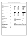
1
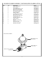
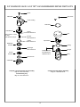
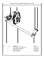
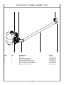
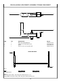
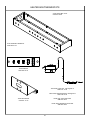
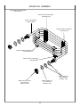
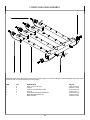
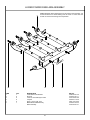
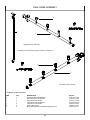
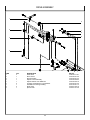
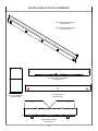
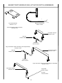
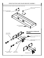
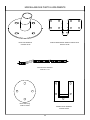
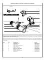
AJ-64 RACK CONVEYOR DISHMACHINES
S
E
R
V
I
C
E
MODELS COVERED IN THIS MANUAL:
AJ-64CE
(ELECTRICALLY-HEATED)
AJ-64CS
(STEAM-HEATED)
M
A
N
U
A
L
March 7, 2003
P/N 7610-002-30-93 (Revision A)
www.jacksonmsc.com
TABLE OF CONTENTS
SECTION
I.
DESCRIPTION
PAGE
GENERAL SECTION
Specifications
1
INSTALLATION & OPERATION SECTION
Installation Instructions
Operating Instructions
2
3
III.
TROUBLESHOOTING SECTION
4
IV.
DIMENSIONS
6
V.
PARTS SECTION
Control Box Assembly
Incoming Plumbing Assembly
WPRK Plumbing Option
External Electric Booster Option Incoming Plumbing
External Electric Booster Option Incoming Plumbing
3/4” Solenoid Valve & 3/4” NPT Vacuum Breaker Repair Parts Kits
Steam Inlet Plumbing Assembly
Steam Outlet Plumbing Assembly (Bottom)
Steam Outlet Plumbing Assembly (Top)
Drain Plumbing Assembly
Drain Handle Weldment Assembly/Frame Weldment
Heater Box/Thermostats
Motors/Motor Support Bracket Assembly
Steam Coil Assembly
Wash Pump Assembly
Pump Weldments
Assorted Gaskets
Heaters/Hood Weldments/Tub Weldments/Wash Manifold
Upper Wash Arm Assembly
Lower Wash Arm Assembly
Upper Power Rinse Arm Assembly
Lower Power Rinse Arm Assembly
Final Rinse Assembly
Drive Assembly
Wash Door and Vent Cowl Assembly
Miscellaneous Door Assemblies
Magnet Switches/Rack Rail Actuator Switch Assemblies
Pawl Bar Assembly/Rack Rail Weldments
Rinse Tray/Pawl Bar Roller Bracket Assembly
Miscellaneous Parts and Weldments
Strainers
Float Switch Assembly
Curtains
Vent Scoop Option/Exhaust Fan Control Option
Table Limit Switch Option
Drain Quench System (Conveyor Series)
8
10
11
12
13
14
15
17
18
19
20
21
22
23
24
25
26
27
28
29
30
31
32
33
37
38
39
40
41
42
44
45
46
47
48
49
SCHEMATICS
208 Volt/230 Volt - 60 Hz - Single Phase Schematic (AJ-64CE)
208 Volt/230 Volt - 60 Hz - Three Phase Schematic (AJ-64CE)
460 Volt - 60 Hz - Three Phase Schematic (AJ-64CE)
208 Volt/230 Volt - 60 Hz - Single Phase Schematic (AJ-64CS)
208 Volt/230 Volt - 60 Hz - Three Phase Schematic (AJ-64CS)
460 Volt - 60 Hz - Three Phase Schematic (AJ-64CS)
50
51
52
53
54
55
II.
VI.
i
SPECIFICATIONS of the AJ-64CE/AJ-64CS
RACKS PER HOUR:
AJ-64CE:
AJ-64CS:
ELECTRICAL REQUIREMENTS:
287
287
AJ-64CE (ALL ARE 60 HZ FREQUENCY):
VOLTS
PHASE
APPROX. AMPS
208
230
SINGLE
SINGLE
140 AMPS
128 AMPS
208
230
460
THREE
THREE
THREE
82 AMPS
76 AMPS
38 AMPS
DISHES OR GLASSES PER HOUR:
AJ-64CE:
AJ-64CS:
7200
7200
WASH TANK CAPACITY (GALLONS):
AJ-64CE:
AJ-64CS:
15.4
15.4
AJ-64CS (ALL ARE 60 HZ FREQUENCY):
WASH PUMP CAPACITY (GPM):
AJ-64CE:
AJ-64CS:
270
270
VENTING REQUIREMENTS (CFM)(100% CAP.):
INPUT END:
OUTPUT END:
TOTAL:
200
400
600
PHASE
APPROX. AMPS
208
230
SINGLE
SINGLE
19 AMPS
19 AMPS
208
230
460
THREE
THREE
THREE
13 AMPS
13 AMPS
7 AMPS
STEAM REQUIREMENTS (PSIG):
AJ-64CE:
AJ-64CS:
CONVEYOR SPEED (FPM):
AJ-64CE:
AJ-64CS:
VOLTS
8.0
8.0
N/A
10 - 20
STEAM COIL SIZE IPS (INCHES):
AJ-64CE:
AJ-64CS:
N/A
3/4
GALLONS PER RACK:
STEAM CONSUMPTION @ 15 PSIG (LBS/HR):
AJ-64CE:
AJ-64CS:
0.77
0.77
AJ-64CE:
AJ-64CS:
WATER TEMPERATURES (°F):
N/A
100
NOTE: Always refer to the machine data plate for specific
electrical and water requirements. The material provided on
this page is for reference only and may be subject to change
without notice.
ALL MODELS:
WASH (MINIMUM)
POWER RINSE (MINIMUM)
FINAL RINSE (MINIMUM)
150
160
180
FLOW PRESSSURE (PSI)
20 A5
FLOWRATE (GPM)
3.7
1
INSTALLATION INSTRUCTIONS
Jackson MSC Inc. provides technical support for all of the dishmachines
detailed in this manual. We strongly recommend that you refer to this manual before making a call to our technical support staff. Please have this
manual with you when you call so that our staff can refer you, if necessary,
to the proper page. Technical support is avaliable from 8:00 a.m. to 5:00
p.m. (EST), Monday through Friday. Technical support is not available on
holidays. Contact technical support toll-free at 1-888-800-5672. Please
remember that technical support is available for service personnel only.
Non-service personnel should refer to the list of provided service agencies
in this manual for local service support.
Do not confuse static pressure with flow pressure. Static pressure is the
line pressure in a “no flow” condition (all valves and services are closed).
Flow pressure is the pressure in the fill line when the fill valve is opened
during the cycle.
It is recommended that a shock absorber (not supplied) be installed in the
incoming water line. This prevents line hammer (hydraulic shock), induced
by the solenoid valve as it operates, from causing damage to the equipment.
PLUMBING CHECK: Slowly turn on the water supply to the machine after
the incoming fill line and the drain line have been installed. Check for any
leaks and repair as required. All leaks must be repaired prior to placing the
machine in operation.
VISUAL INSPECTION: Before installing the unit, check the container and
machine for damage. A damaged container is an indicator that there may
be some damage to the machine. If there is damage to both the container
and machine, do not throw away the container. The dishmachine has been
inspected and packed at the factory and is expected to arrive to you in
new, undamaged condition. However, rough handling by carriers or others
may result in there being damage to the unit while in transit. If such a situation occurs, do not return the unit to Jackson; instead, contact the carrier and ask them to send a representative to the site to inspect the damage
to the unit and to complete an inspection report. You must contact the carrier within 48 hours of receiving the machine. Also, contact the dealer
through which you purchased the unit.
ELECTRICAL POWER CONNECTION: Electrical and grounding connections must comply with the applicable portions of the National Electrical
Code ANSI/NFPA 70 (latest edition) and/or other electrical codes.
Disconnect electrical power supply and place a tag at the disconnect
switch to indicate that you are working on the circuit.
The dishmachine data plate is located on the right side and to the front of
the machine. Refer to the data plate for machine operating requirements,
machine voltage, total amperage load and serial number.
UNPACKING THE DISHMACHINE: Once the machine has been removed
from the container, ensure that there are no missing parts from the
machine. This may not be obvious at first. If it is discovered that an item is
missing, contact Jackson immediately to have the missing item shipped to
you.
To install the incoming power lines, open the control box. Install conduit
into the pre-punched holes in the back of the control box. Route power
wires and connect to power block and grounding lug. Install the service
wires (L1, L2, and L3 (3 phase only)) to the appropriate terminals as they
are marked on the terminal block. Install the grounding wire into the lug
provided. Tighten the connections. It is recommended that “DE-OX” or
another similar anti-oxidation agent be used on all power connections.
LEVEL THE DISHMACHINE: The dishmachine is designed to operate
while being level. This is important to prevent any damage to the machine
during operation and to ensure the best results when washing ware. The
unit comes with adjustable bullet feet, which can be turned using a pair of
channel locks or by hand if the unit can be raised safely. Ensure that the
unit is level from side to side and from front to back before making any
connections.
VOLTAGE CHECK: Ensure that the power switch is in the OFF position
and apply power to the dishmachine. Check the incoming power at the terminal block and ensure it corresponds to the voltage listed on the data
plate. If not, contact a qualified service agency to examine the problem. Do
not run the dishmachine if the voltage is too high or too low. Shut off the
service breaker and mark it as being for the dishmachine. Advise all proper personnel of any problems and of the location of the service breaker.
Replace the control box cover and tighten down the screws.
PLUMBING THE DISHMACHINE: All plumbing connections must comply
with all applicable local, state, and national plumbing codes. The plumber
is responsible for ensuring that the incoming water line is throroughly
flushed prior to connecting it to any component of the dishmachine. It is
necessary to remove all foreign debris from the water line that may potentially get trapped in the valves or cause an obstruction. Any valves that are
fouled as a result of foreign matter left in the water line, and any expenses resulting from this fouling, are not the responsibility of the manufacturer.
VENTILATION OF DISHMACHINE: The dishmachine should be located
with provisions for venting into an adequate exhaust hood or ventilation
system. This is essential to permit efficient removal of the condensation
exhaust. Ensure that the exhaust system is acceptable in accordance with
all applicable codes and standards.
CONNECTING THE DRAIN LINE: All piping from the machine to the drain
must be a minimum 1-1/2” I.P.S. and shall not be reduced. There must also
be an air gap between the machine drain line and the floor sink or drain. If
a grease trap is required by code, it should have a flow capacity of 30 gallons per minute.
NOTE: Damage caused by steam or moisture due to improper ventilation is NOT covered under the warranty.
This units covered in this manual have the following exhaust requirements:
WATER SUPPLY CONNECTION: Ensure that you have read the section
entitled “PLUMBING THE DISHMACHINE” above before proceding. Install
the water supply line (3/4” pipe size minimum) to the dishmachine line
strainer using copper pipe. It is recommended that a water shut-off valve
be installed in the water line between the main supply and the machine to
allow access for service. The water supply line is to be capable of 20 A5
PSI “flow” pressure at the recommended temperature indicated on the
data plate.
Load End:
Unload End:
200 CFM
400 CFM
The exhaust system must be sized to handle this volume for the dishmachine to operate as it was designed to.
ELECTRIC HEAT: The thermostats for the machines covered in this manual are factory set. They should not be adjusted except by an authorized
service agent.
In areas where the water pressure fluctuates or is greater than the recommended pressure, it is suggested that a water pressure regulator be
installed. The models covered in this manual do not come with water pressure regulators as standard equipment.
STEAM LINE CONNECTIONS: The machines covered in this manual are
designed to use low pressure steam as a source of heat for wash tank
water. The machines come with lines by which the source steam needs to
be connected. Connect all steam lines to the machine as all applicable
codes provide.
2
INSTALLATION INSTRUCTIONS (CONTINUED)/OPERATING INSTRUCTIONS
OPERATING INSTRUCTIONS
CHEMICAL FEEDER EQUIPMENT: Detergent may be introduced into the
unit through the removal of the bulkhead plug in the rear of the tub and
replacing it with the third party detergent injection fitting. Remove the bulkhead plug in the side of the tub to install the detergent concentration
probe.
PREPARATION: Before proceeding with the start-up of the unit, verify the
following:
1. Close door(s) on dishmachine.
The 1/8” brass plugs on the incoming plumbing rinse injector may be
removed to install rinse aid injection fittings.
2. Close the drain valve(s).
POWER UP: To energize the unit, turn on the power at the service breaker. The voltage should have been previously verified as being correct. If
not, the voltage will have to be verified. In accordance with the manufacturer’s instructions you should also activate the steam booster and allow
for flow of steam to the unit.
All wires for the chemical injectors should be routed through the back of
the control box.
Terminals in the control box marked “CVS” provide a constant voltage signal whenever the drive motor is operating.
FILLING THE WASH TUB: Ensure that the delime switch is in the NORMAL position, and place the power switch into the ON position. The
machine should fill automatically and shut off when the appropriate level is
reached (just below the pan strainer). The wash tub must be completely
filled before operating the wash pump to prevent damage to the component. Once the wash tub is filled, the unit is ready for operation.
Terminals in the control box marked “DET” provide a voltage signal whenever the wash motor is operating.
DELIMING OPERATIONS: In order to maintain the dishmachine at its
optimum performance level, it will be required to remove lime and corrosion deposits on a frequent basis. A deliming solution should be available
from your detergent supplier. Read and follow all instructions on the label
of the deliming solution.
WARE PREPARATION: Proper preparation of ware will help ensure good
results and less re-washes. If not done properly, ware may not come out
clean and the efficiency of the dishmachine will be reduced. It is important
to remember that a dishmachine is not a garbage disposal and that simply throwing unscrapped dishes into the machine simply defeats the purpose altogether of washing the ware. Scraps should be removed from
ware prior to being loaded into a rack. Pre-rinsing and pre-soaking are
good ideas, especially for silverware and casserole dishes. Place cups
and glasses upside down in racks so that they do not hold water during the
cycle. The dishmachine is meant not only to clean, but to sanitize as well,
to destroy all of the bacteria that could be harmful to human beings. In
order to do this, ware must be properly prepared prior to being placed in
the machine.
To proceed with the deliming operation, fill the dishmachine and add the
correct amount of deliming solution as recommended by the deliming solution manufacturer. The water capacity of the various tanks of the dishmachine can be verified on the specification sheet(s) of this manual.
Perform the following operations to delime the dishmachine:
1. Turn the NORMAL/DELIME switch on the back of the control box to the
DELIME position.
2. Disconnect or turn off all chemical feeder pumps.
DAILY MACHINE PREPARATION: Refer to the section entitled “PREPARATION” at the top of this page and follow the instructions there.
Afterwards, check that all of the chemical levels are correct and/or that
there is plenty of detergent available for the expected workload.
3. Close all doors (after adding the deliming solution).
4. Run the machine for the recommended period of time.
WASHING A RACK OF WARE: To wash a rack, simply slide a rack of
soiled ware into the load end of the machine. Once the the machine is
started, it should pull the rack through the machine and push it out the
unload end. Once a rack has started through, you may put another rack in.
5. Turn the unit off and open the doors.
6. Wait five minutes, then inspect the inside of the machine. If the machine
is not delimed, run another time cycle as per the deliming solution’s
instructions.
OPERATIONAL INSPECTION: Based upon usage, the pan strainers may
become clogged with soil and debris as the workday progresses.
Operators should reguarly inspect the pan strainers to ensure they have
not become clogged. If the strainers do, they will reduce the washing capability of the machine. Instruct operators to clean out the pan strainers at
regular intervals or as required by work load.
7. When clean, drain and re-fill the machine.
8. Run in MANUAL for 10 minutes to remove residual deliming solution.
9. Drain and re-fill the machine.
SHUTDOWN AND CLEANING: At the end of the workday, place the
power switch in the OFF position and open the door(s). Steam-heated
units need to have the steam secured to the machine prior to any cleaning. Open the drain valves and allow the machine to drain completely.
Remove the pawl bar assembly (clean as required). Remove the pan
strainers and, if equiped, the prewash strainers, run off sheets and scrap
basket strainer. Remove the wash and, if equipped, the prewash arms and
verify that the nozzles and arms are free from obstructions. Flush the arms
with fresh water. Remove the pump suction strainers and clean out as
required. Remove the rinse tray assembly and clean. Remove the curtains
and scrub with a mild detergent and warm water. Wipe out the inside of the
unit and then reassemble with the components previously removed.
This equipment is not recommend for use with deionized water or
other aggressive fluids. Use of deionized water or other aggressive
fluids will result in corrosion and failure of materials and components. Use of deionized water or other aggressive fluids will void the
manufacturer's warranty.
3
TROUBLESHOOTING SECTION
Problem: Nothing on dishmachine operates. The power switch is ON and the power indicator light is OFF.
1. Machine is not wired correctly to incoming power source. Have an electrician verify wiring.
2. Machine circuit breaker is tripped. Reset the circuit breaker. If it trips again, contact an electrician to verify the machine amp draw.
3. Service breaker is tripped. Reset the service breaker. If it trips again, contact an electrician to verify the machine amp draw.
Problem: Machine will not fill. The power switch is ON and the power indicator light is ON.
1. No water supply to machine. Verify that water lines have been connected to the machine.
2. Dishmachine doors are not closed. Close doors completely.
3. Incoming water solenoid valve damaged/faulty. Verify that the valve is operating. If not, replace.
4. Tank floats faulty. Verify the wiring of the floats. Verify that no debris is jamming the floats. Replace if necessary.
Problem: Machine fills, but fill is weak.
1. Low incoming water pressure. Verify that incoming water pressure during fill is 20 A5 PSI.
2. Incoming water solenoid is clogged. Verify that debris is not entrapped in valve. If so, remove debris.
Problem: Low wash tank temperature.
1. Low incoming water temperature. Verify that the incoming water temperature matches what is indicated on the machine data plate.
2. Heater not energizing. Verify that the wash tank heater is operating. If not, replace.
3. Low incoming voltage. Have an electrician verify that the power coming to the machine is the same as indicated on the data plate.
Problem: Low wash arm pressure, poor spray pattern.
1. Clogged wash arm nozzles. Verify that nozzles are not clogged with debris. If so, remove debris.
2. Clogged wash tank or wash pump strainers. Clean out strainers if necessary.
3. Worn wash pump impeller. Verify status of impeller, replace if necessary.
Problem: Low prewash arm pressure, poor spray pattern.
1. Clogged prewash arm nozzles. Verify that nozzles are not clogged with debris. If so, remove debris.
2. Clogged prewash tank or prewash pump strainers. Clean out strainers if necessary.
3. Worn prewash pump impeller. Verify status of impeller, replace if necessary.
Problem: Inadequate rinse.
1. Low incoming water pressure. Verify that incoming water pressure during fill is 20 A5 PSI.
2. Incoming water solenoid is clogged. Verify that debris is not entrapped in valve. If so, remove debris.
Problem: Pawl bar moves with no load, but does not move when loaded.
1. Clutch on drive assembly is out of adjustment. Adjust as required.
Problem: Pawl bar does not move.
1. Failed or broken overload spring. Replace spring if necessary.
2. No power to the drive motor/failed drive motor. Verify power and wiring connections to the motor. If necessary, replace the motor.
3. Pawl bar not properly installed. Verify that the pawl bar is installed correctly.
Problem: Racks go through the machine, but results are poor.
1. Verify that detergent is being dispensed into the machine at the appropriate quantities for the water volume. If not, get detergent to appropriate level
and review results of washing ware.
2. Clogged strainers/scrap basket. Clean out strainers and scrap basket and replace.
3. Ware not being properly prescrapped. Review paragraph entitled ‘Ware Preparation” in Operating Instructions.
4. Wash or rinse arms missing end plugs or caps. Verify and replace as required.
5. Low tank heat (see previous page).
6. Inadequate rinse (see previous page).
7. Incorrect voltage coming to the machine. Verify that the voltage matches that on the machine data plate.
8. Wash pump cavitation due to low water level. Verify that the drains are shut and that the water level is correct.
4
TROUBLESHOOTING SECTION (CONTINUED)
Problem: Spotting of silverware, glasses and dishes.
1. Incorrect final rinse temperature. Verify that the rinse water temperature matches that which is listed on the machine data plate.
2. Clogged wash and/or rinse nozzles and arms. Remove the arms and verify that they and their nozzles are from debris.
3. Excessively hard water. Install a water softener to reduce hardness.
4. Loss of water pressure due to clogged/obstructed wash pump. Turn the power off to the machine at the source. Drain the wash tank of water and
verify that the pump intake is free from debris.
5. Improper scrapping procedures. Review the paragraph entitled “Ware Preparation” in Operating Instructions.
6. incorrect detergent/chemcial concentrations. Verify that the detergent/chemical concentrations are correct for the associated water volume.
TORQUE SETTINGS
When replacing components either in the control box or the heater box area, the manufacturer has suggestions on how much to torque the screws
and nuts used in securing items to the machine. Refer to the table below for the torque specifictions:
ITEMS
TORQUE SPEC
Relays
Heater Contactor
Heater Nuts
Terminal Block
16 In/lbs
35 In/lbs
16 In/lbs
50 In/lbs
5
DIMENSION PAGES LEGENDS/TABLE DIMENSIONS
The following pages contained dimensioned drawings to be used as references when installing your machine. The drawings also have
several key points indicated , which can be referenced using the table below:
LETTER
DESCRIPTION
A
Electrical Connection - See Data Plate for Amperage Requirements
B
Water Inlet - 3/4” I.P.S. 180°F Water Required
C
Drain Connection - 1-1/2” I.P.S.
D
Vent Collar/Splash Shield
E
Vent Collar with Damper (4” W x 16” Lg x 7” High) Optional
F
Steam Connection 1” I.P.S.
G
Condensate Return 1” I.P.S.
All dimensions from a finished floor ar +/- 1/2” with the adjustable feet.
Utility connections, unless specifically noted, are identical regardless of direction of operation.
The material provided on this page is for reference only and may be subject to change without notice.
TABLE DIMENSIONS
21”
3/4”
6
TOP VIEW
AJ-64 DIMENSIONS
7
19
22
18
23 21
17
20
16
15
15
14
13
10
12
11
9
6
8
7
5
4
3
2
1
CONTROL BOX ASSEMBLY
8
CONTROL BOX ASSEMBLY (CONTINUED)
ITEM
1
2
3
QTY
1
1
1
1
1
12
3
13
14
15
16
17
18
19
20
21
22
23
1
1
0
1
1
1
0
3
1
1
1
DESCRIPTION
Electrical Box Weldment
Electrical Box Inner Panel
Decal, Copper Conductors Only
Decal, Guage, AJ-64
Terminal Block
Decal, L1-L2-L3
Ground Lug
Decal, Ground
Light, Amber (Not used on steam models)
Light, Red
Not Applicable for AJ-64 Models
Not Applicable for AJ-64 Models
Circuit Breaker (208-230 volt models)
Power Switch
Overload, 1-1.5 RT1G (Drive Motor)(208-230 volt, 3 phase models)
Overload, .4-.63 RT1D (Drive Motor)(460 volt, 3 phase models)
Overload, 5.5-8.5 RT1M (Wash Motor)(208-230 volt, 3 phase models)
Overload, 4.0-6.3 RT1L (Wash Motor)(460 volt, 3 phase models)
Contactor, Motor
Din Rail, 5-3/4” Long
Contactor, Heater (Not used on steam models)
Contactor, Heater (Not used on steam models)
Not Applicable for AJ-64 Models
Rinse Thermometer
Power Rinse Thermometer
Wash Thermometer
Not Applicable for AJ-64 Models
Relay, 2 Pole
Terminal Board
Terminal Board
Relay, 3 Pole
4
1
5
6
7
8
9
10
11
2
1
0
0
1
1
1
1
1
1
1
1
4
Manual/Delime Switch
Manual/Delime Switch Decal
Decal, High Limit Warning Light
Transformer, 150V, 60 Cycle
Control Box Cover
Control Box Leg
5930-301-22-18
9905-011-74-61
9905-002-49-48
5950-011-68-35
5700-031-91-17
5700-011-71-47
Fuse, 1/2 Amp
Holder, Fuse
5920-011-72-88
5920-011-72-89
2
Mfg. No.
5700-041-88-44
5700-031-81-63
9905-011-47-35
9905-021-82-65
5940-011-48-27
9905-101-12-66
5940-200-76-00
9905-011-86-86
5945-111-44-44
5945-111-44-45
N/A
N/A
5925-011-68-34
5930-301-46-00
5945-111-68-39
5945-111-69-12
5945-111-68-40
5945-111-81-33
5945-111-68-38
5700-021-72-75
5945-002-24-70
5945-002-24-70
N/A
6685-111-68-49
6685-111-68-49
6685-111-87-13
N/A
5945-111-35-19
5940-021-70-70
5940-021-89-41
5945-111-72-51
Items not shown:
460 volt models only:
1
1
NOTICE: The control box pictured on the previous page is of the AJ-86 variety which is an AJ-64 machine with an additonal
prewash section. This accounts for any cosmetic differences.
9
1
2
4
6
5
7
3
6
12
17
8
9
2
5
5
13, 14
4 6
13
18
17
7
8
6
9
20
22
10
14, 15, 16
10
21
22
11
8
9
6
7
6
5
4
12
5
9
19
INCOMING PLUMBING ASSEMBLY
10
INCOMING PLUMBING ASSEMBLY (CONTINUED)/WPRK PLUMBING OPTION
ITEM
1
2
3
4
5
6
7
8
9
10
11
12
13
14
15
16
17
18
19
20
21
22
QTY
1
2
3
3
5
6
3
3
4
2
1
2
2
2
1
1
2
1
1
1
1
2
DESCRIPTION
Injector, Rinse Weldment
Fill Line, Injector
Plug, 1/8” NPT, Brass
Vacuum Breaker, 3/4” NPT, Brass
Elbow, 3/4” NPT, Street, Brass
Nipple, 3/4” NPT, Close, Brass
Valve, Solenoid, 3/4” NPT, 110 Volt
Union, 3/4” NPT, Brass
Adapter, 3/4” Male
Tee, Copper, 3/4” CU x CU x CU
Tube, Copper, 3/4” x 3” Long
Nipple, 3/4” NPT, Brass, 6” Long
Tee, Copper, 3/4” x 3/4” x 1/2”
Adapter, Threaded, 1/4”
Valve, Ball, Test Cock, 1/4” NPT
Gauge, 0-100 PSI
Tube, 3/4” x 2-13/16” Long
Plug, 1/4”
Regulator, Pressure, 3/4” NPT
Tube, 3/4” x 9” Long
Tube, 3/4” x 16-1/4” Long
Tube, 3/4” x 5-1/2” Long
Mfg. No.
5700-021-67-98
5700-011-67-99
4730-209-07-37
4820-300-08-00
4730-206-04-34
4730-207-34-00
4810-100-53-00
4730-212-05-00
4730-401-11-01
4730-411-46-01
5700-000-54-85
5700-001-26-74
4730-411-03-01
4730-401-41-01
4810-011-72-67
6685-111-88-34
5700-011-72-72
4730-209-01-00
6685-011-58-22
5700-000-75-61
5700-011-31-48
5700-002-61-46
WPRK OPTION PLUMBING
Water Arrestor, 1/2” NPT
6685-100-05-00
Tee, 3/4” x 3/4” x 1/2”
4730-211-06-00
Nipple, 3/4” NPT, Close, Brass
4730-207-34-00
11
EXTERNAL ELECTRIC BOOSTER OPTION INCOMING PLUMBING
2
5
Plumbing with Water Hammer Arrestor
1
6
7
11
3
ITEM
1
2
3
4
5
6
7
8
9
10
11
QTY
--------------------------------------------------------
4
3
2
DESCRIPTION
Y-Strainer, 3/4” NPT, Brass
Adapter, 3/4” Male
Tube, Copper, 3/4” x 3-7/16” Long
Tee, Copper, 3/4” x 3/4” x 1/2”
Arrestor, 1/2” NPT, Water Hammer
Adapter, 1/2” NPT x Male
Regulator, Pressure, 3/4” NPT, Brass
Nipple, 3/4” NPT x 2” Long, Brass
Elbow, Brass, 90 Degree, 3/4”
Nipple, 3/4”, Brass, Close
Coupling, 3/4” FNPT x 3/4” FNPT, Brass
8
9
10
Mfg. No.
4730-717-02-06
4730-401-11-01
5700-011-72-70
4730-411-03-01
6685-100-05-00
4730-401-07-01
6685-011-58-22
4730-207-46-00
4730-206-13-00
4730-207-34-00
4730-011-87-95
Plumbing without Water Hammer Arrestor
10
7
1
8
11
9
10
12
EXTERNAL ELECTRIC BOOSTER OPTION OUTLET PLUMBING
6
9
8
7
6
4
5
2
3
ITEM
1
2
3
4
5
6
7
8
9
1
QTY
1
1
1
1
1
2
1
1
1
DESCRIPTION
Elbow, Brass, 90 Degree, 3/4”
Nipple, 3/4” NPT x 2” Long, Brass
Union, 3/4” NPT, Brass
Adapter, 3/4”, Male
Tube, Copper, 3/4” x 24” Long
Elbow, 3/4” Copper to Copper (Female)
Tube, Copper, 3/4” x 49-1/2” Long
Elbow, 3/4”, 90 Degree Street, Copper to Copper
Tube, Copper, 3/4” x 5-7/8” Long
13
Mfg. No.
4730-206-13-00
4730-207-46-00
4730-212-05-00
4730-401-11-01
5700-021-76-53
4730-406-16-01
5700-031-87-98
4730-406-40-01
5700-011-87-96
3/4” SOLENOID VALVE & 3/4” NPT VACUUM BREAKER REPAIR PARTS KITS
Screw
Data Plate
Cap Screw
Coil & Housing
Data Plate
Valve Bonnet
Spring position is moved
for clarity.
Goes below the plunger.
Spring
4810-200-04-18
Cap
Plunger
4810-200-04-18
O-Ring
4810-100-10-18
Cap Retainer
Diaphragm
Retainer
O-Ring
Diaphragm
4810-100-10-18
Plunger
COMPONENTS
OF REPAIR KIT
4820-001-60-57
Screen
Retainer
Body
Mesh Screen
Valve Body
Complete 110 Volt Solenoid Valve Assembly
Mfg. No.: 4810-100-53-00
Coil & Housing only
Mfg. No.: 4810-200-01-18.
Complete Vacuum Breaker Assembly
Mfg. No.: 4820-300-08-00.
14
STEAM INLET PLUMBING ASSEMBLY
10
9
7
8
11
12
15
16
15
6
TOP VIEW
2
1
3
14
FRONT VIEW
4
5
11
11
11
15
12
13
9
9
STEAM INLET PLUMBING ASSEMBLY (CONTINUED)
ITEM
1
2
3
4
5
6
7
8
9
10
11
12
13
14
15
16
QTY
1
1
1
1
1
1
2
6
4
1
4
5
1
1
2
2
DESCRIPTION
Valve, 1” Gate
Nipple, 1” NPT, Close, Black Iron
Y-Strainer, 1” NPT, Black Iron
Reducer, 1” NPT to 3/4” NPT
Nipple, 3/4” NPT x 6” Long, Black Iron
Tee, 3/4” x 3/4” x 3/4”, Black Iron
Nipple, 3/4” NPT x 4” Long, Black Iron
Elbow, Street, 3/4” NPT, 90 Degree, Black Iron
Elbow, 3/4” NPT, 90 Degree, Black Iron
Nipple, 3/4” NPT x 7” Long, Black Iron
Union, 3/4” NPT, Black Iron
Nipple, 3/4” NPT, Close, Black Iron
Nipple, 3/4” NPT x 17” Long, Black Iron
Nipple, 3/4” NPT x 26.5” Long, Black Iron
Valve, Solenoid, Steam, 3/4” NPT, 120V
Reducer, 3/4” NPT to 1/2” NPT
Mfg. No.
4820-011-87-30
4730-907-08-34
4730-217-02-32
4730-011-95-66
4730-907-01-34
4730-002-74-14
4730-907-02-34
4730-011-87-37
4730-906-10-34
5700-002-74-15
4730-912-01-00
4730-907-01-00
5700-002-74-16
5700-002-74-17
4820-011-87-39
4730-911-02-34
12
8
RIGHT SIDE VIEW
16
STEAM OUTLET PLUMBING ASSEMBLY (BOTTOM)
6
7
3
4
5
1
2
ITEM
1
2
3
4
5
6
7
QTY
1
2
1
1
1
1
1
2
DESCRIPTION
Nipple, 3/4” NPT x 18” Long, Black Iron
Elbow, 90 Degree, Street, 3/4” NPT, Black Iron
Elbow, 90 Degree, 3/4” NPT, Black Iron
Reducer, 3/4” NPT to 1/2” NPT
Union, 3/4” NPT, Black Iron
Nipple, Close, 3/4” NPT
Steam Trap, 3/4” NPT
17
Mfg. No.
5700-002-74-10
4730-011-87-37
4730-906-10-34
4730-911-02-34
4730-912-01-00
4730-907-01-00
6680-500-02-77
STEAM OUTLET PLUMBING ASSEMBLY (TOP)
1
2
ITEM
1
2
3
4
5
6
7
QTY
1
1
1
1
1
1
1
3
7
4
5
DESCRIPTION
Steam Trap
Nipple, Close, 3/4”, Black Iron
Union, 3/4” NPT, Black Iron
Elbow, Street, 90 Degree, Black Iron
Nipple, 3/4” NPT x 22” Long, Black Iron
Elbow, 90 Degree, 3/4” FNPT, Black Iron
Reducer, 3/4” NPT x 1/2” NPT
18
6
Mfg. No.
6680-500-02-77
4730-907-01-00
4730-912-01-00
4730-011-87-37
5700-002-74-08
4730-906-10-34
4730-911-02-34
DRAIN PLUMBING ASSEMBLY
1
7
5
4
3
9
2
8
8
2
10
NOTE 1
7
6
6
ITEM
1
2
3
4
5
6
7
8
9
10
3
4
QTY
2
3
4
4
2
2
2
2
1
1
2
3
4
DESCRIPTION
Ball Valve Handle Assembly
Tee, Brass, 1-1/2” x 1-1/2” x 1-1/2”
Adapter, 1-1/2”
Tube, Copper, 1-1/2” OD x 2” Long
Connector, No-Hub, 1-1/2”
Elbow, 1-1/2”, Street, Brass, 90 Degree
Valve, Ball, 1-1/2” NPT
Nipple, 1-1/2” NPT, Brass, Close
Rinse Nipple Weldment
Fitting, Barbed, 1-1/2” NPT x 1-1/2”
5
4
3
1
Mfg. No.
5700-021-84-74
4730-011-69-93
4730-401-25-01
5700-011-87-16
4720-604-06-00
4730-206-32-00
4820-111-71-46
4730-207-40-00
5700-021-84-61
4730-011-69-92
NOTE 1: Component is shown for installation in a Right-to-Left model; component is rotated 180 degrees for Left-to-Right units.
19
DRAIN HANDLE WELDMENT ASSEMBLY/FRAME WELDMENT
1
2
4
3
ITEM
1
2
3
4
QTY
1
1
1
1
DESCRIPTION
Ball Valve Handle Weldment
Locknut, 1/4”-20 with Nylon Insert
Spacer
Screw, 1/4”-20 x 2” Long Hex Head
Mfg. No.
5700-021-70-42
5310-374-01-00
5700-000-01-53
5306-011-84-72
FRAME WELDMENT
1
2
Item 1:
Model
AJ-64CE/AJ-64CS
Left to Right P/N
5700-002-73-00
Right to Left P/N
5700-0002-73-00
Item 2:
Bullet Feet (4 per model) - order using part number 5340-011-71-74.
Flanged Bullet Feet (4 per model) - order using part number 5340-002-15-47.
20
HEATER BOX/THERMOSTATS
AJ-64 Heater Box Cover
5700-031-81-61
AJ-64 Heater Box Weldment
5700-002-41-18
Terminal Board
5940-021-70-70
Thermostat, High Limit, 104 Degrees C
5930-121-71-36
Thermostat, Wash Regulating, 78 Degrees C
5930-121-67-72
Decal, High Limit Thermostat
9905-011-84-31
Thermostat Bracket
5700-011-73-72
Decal, Wash Regulating Thermostat
9905-011-84-31
21
MOTORS/MOTOR SUPPORT BRACKET ASSEMBLY
The chart below details the part numbers for the various models covered in this manual. Refer to the machine data plate for voltage
and phase information.
Model
Volts
Phase
AJ-64CE/CS
AJ-64CE/CS
AJ-64CE/CS
AJ-64CE/CS
AJ-64CE/CS
208
230
208
230
460
1
1
3
3
3
Power Rinse Motor P/N
Wash Motor P/N
Drive Motor P/N
6105-021-70-57
6105-021-70-57
6105-121-70-58
6105-121-70-58
6105-121-70-58
6105-021-70-57
6105-021-70-57
6105-121-70-58
6105-121-70-58
6105-121-70-58
6105-121-70-53
6105-121-70-53
6105-121-70-54
6105-121-70-54
6105-121-70-54
The clamp used to secure the pump motor to the bracket may be ordered using
part number 4730-002-32-15.
The locknuts (1/4”-20 Hex with Nylon Insert) used to secure the assembly to the
tub bottom may be ordered using part number 5310-374-01-00.
3
1
2
ITEM
1
2
3
QTY
1
1
1
DESCRIPTION
Upper Pump Support Bracket Weldment
Lower Pump Support Bracket Weldment
Nut, Serrated, 1/4”-20, Hex
Entire Assembly
22
Mfg. No.
5700-021-73-68
5700-021-73-71
5310-011-66-49
5700-021-73-42
STEAM COIL ASSEMBLY
Complete Steam Coil Assembly
5700-041-88-31
Stand C, Steam Coil Support
5700-002-74-84
Steam Coil Weldment
5700-031-88-30
Stand D, Steam Coil Support
5700-002-74-85
Stand B, Steam Coil Support
5700-002-74-83
Stand A, Steam Coil Support
5700-002-74-82
Gasket, Steam Coil
4 per assembly
5700-001-17-86
Washer, Steam Coil
2 per assembly
5700-001-17-87
Adapter, Steam Coil Nut
2 per assembly
5700-011-17-85
23
WASH PUMP ASSEMBLY
15
10
8
1
4
7
12
14
ITEM
1
2
3
4
5
6
7
8
9
10
11
12
13
14
15
QTY
1
1
1
4
1
1
4
1
1
1
1
1
1
1
2
13
11
9
6
5
DESCRIPTION
See Page Entitled “Pump Support Bracket Assembly”
Hose Clamp, 4-1/8” - 7”, HSS104
See Page Entitled “Motors”
Nut, Hex, 3/8”-16, S/S
Pump Plate
Pump Seal
Bolt, 3/8”-16 x 2” Long Hex Head
Key, 3/16” x 1” Long
Impeller
Impeller Washer
Bolt, 1/4”-20 x 3/4” Long
Pump Manifold Hose
See Page Entitled “Assorted Gaskets”
See Page Entitled “Pump Weldments”
Hose Clamp, 1-1/16” - 2”
24
3
2
Mfg. No.
N/A
4730-002-32-15
N/A
5310-276-01-00
5700-021-71-83
5330-011-71-98
5305-011-74-98
5700-011-89-17
5700-031-67-45
5700-011-71-95
5305-274-04-00
5700-002-18-17
N/A
N/A
4730-719-18-00
PUMP WELDMENTS
Wash Pump Weldment
5700-031-81-47
Power Rinse Pump Weldment
5700-041-68-88
The gasket used to seal the weldment to the tub can be found on the page entitled “Assorted Gaskets”.
The pump weldment is secured to the pump plate (through the actual tub wall) using the following fasteners:
Nut, Hex, 3/8”-16
P/N 5310-276-01-00
Washer, Flat, 3/8”
P/N 5311-176-01-00
Lockwasher, Split, 3/8”
P/N 5311-276-01-00
The pump weldment, gasket, and associated fasteners are not available as one assembly and must be ordered separately.
25
ASSORTED GASKETS
Motor Mounting Gasket
5330-011-71-62
Heater Gasket
5330-200-02-70
Rinse Assembly Vellumoid Gasket
5330-111-42-81
Rinse Drain Plate Gasket
5330-011-72-27
Pawl Bar Gutter Gasket
5330-011-68-55
26
HEATERS/HOOD WELDMENTS/TUB WELDMENTS/WASH MANIFOLD
Order your wash heaters using the table below:
Model
Volts
Phase
KW
Part Number
AJ-64CE
AJ-64CE
AJ-64CE
AJ-64CE
AJ-64CE
AJ-64CE
AJ-64CE
AJ-64CE
AJ-64CE
208
208
230
230
208
208
230
230
460
1
1
1
1
3
3
3
3
3
10
15
10
15
10
15
10
15
10
4540-121-76-91
4540-121-68-45
4540-121-76-92
4540-121-68-46
4540-121-91-76
4540-121-68-45
4540-121-76-92
4540-121-68-46
4540-121-76-93
Vent Cowl Cover Weldment
5700-011-74-67
Top Gasket
5330-031-83-47
Side Gasket
5330-031-83-48
Vent Cowl Weldment
5700-041-86-94
Shoulder Bolt Wingnut
Weldment
5700-002-46-02
Wash Manifold Weldment
5700-031-77-24
27
UPPER WASH ARM ASSEMBLY
1
2
3
4
5
6
SERVICE NOTE: When replacing the 10-32 screws in the End Caps, it is recommended that a thread locking fluid be used to ensure
that the screws do not back out during normal operation.
ITEM
1
2
3
4
5
6
QTY
3
3
3
3
1
1
1
DESCRIPTION
Screw, 10-32 x 3/8” Long
Lanyard
Locknut, 10-24 with Nylon Insert
End Cap
Upper Wash Arm Manifold Weldment
Cap, Wash Tube
Entire Assembly
28
Mfg. No.
5305-173-12-00
5340-011-72-46
5310-373-01-00
5700-011-67-11
5700-031-67-34
5700-021-69-68
5700-031-74-99
LOWER WASH ARM ASSEMBLY
4
1
2
3
5
6
SERVICE NOTE: When replacing the 10-32 screws in the End Caps, it is recommended that a thread locking fluid be used to ensure
that the screws do not back out during normal operation.
ITEM
1
2
3
4
5
6
QTY
6
6
6
6
1
1
DESCRIPTION
Screw, 10-32 x 3/8” Long
Lanyard
Locknut, 10-24 with Nylon Insert
End Cap
Lower Wash Arm Manifold Weldment
Manifold Quick-Release Key
Entire Assembly
29
Mfg. No.
5305-173-12-00
5340-011-72-46
5310-373-01-00
5700-011-67-11
5700-031-67-29
5700-011-94-45
5700-031-74-66
UPPER POWER RINSE ARM ASSEMBLY
SERVICE NOTE: When replacing the 10-32 screws in the End Caps, it is recommended that a
thread locking fluid be used to ensure that the screws do not back out during normal operation.
4
5
3
2
ITEM
1
2
3
4
5
6
1
QTY
1
3
3
3
3
1
6
DESCRIPTION
Upper Wash Manifold
End Cap
Lanyard
Screw, 10-32 x 3/8” Long
Locknut, 10-24 with Nylon Insert
Cap, Wash Tube
Entire Assembly
30
Mfg. No.
5700-031-91-48
5700-011-87-11
5340-011-72-46
5305-173-12-00
5310-373-01-00
5700-021069-68
5700-031-91-46
LOWER POWER RINSE ARM ASSEMBLY
2
5
ITEM
1
2
3
4
5
6
1
QTY
1
6
6
6
6
1
SERVICE NOTE: When replacing the 10-32 screws in the End Caps, it is
recommended that a thread locking fluid be used to ensure that the
screws do not back out during normal operation.
4
DESCRIPTION
Lower Wash Arm Manifold
End Cap
Locknut, 10-24 with Nylon Insert
Lanyard
Screw, 10-32 x 3/8” Long
Manifold Quick Release Key
Entire Assembly
31
3
6
Mfg. No.
5700-031-91-49
5700-011-67-11
5310-373-01-00
5340-011-72-46
5305-173-12-00
5700-011-94-45
5700-031-91-47
FINAL RINSE ASSEMBLY
3
1
2
Upper Rinse Arm Assembly
End plugs can be ordered using part number 4730-209-07-37.
5
4
Lower Rinse Arm Assembly
* - Indicates an item not shown
ITEM
1
2
3
4
5
6*
7*
QTY
1
1
4
1
4
2
2
DESCRIPTION
Final Rinse Manifold Weldment
Upper Rinse Arm with Nozzles
Upper Rinse Arm Nozzles
Lower Rinse Arm with Nozzles
Lower Rinse Arm Nozzles
O-Ring (Not Shown)
Ring, Retaining, Rinse Head Bushing (Not Shown)
32
Mfg. No.
5700-031-74-88
5700-021-74-89
5700-011-78-82
5700-021-83-18
5700-011-78-82
5330-011-74-55
5340-112-01-11
DRIVE ASSEMBLY
7
9
3
1
8
2
4
5
6
ITEM
1
2
3
4
5
6
7
8
9
QTY
2
1
1
1
1
2
1
2
1
DESCRIPTION
Pillow Block
Drive Socket
Drive Rod Plate
Adjuster Crank Assembly
Adjuster Skotch Yoke Weldment
Coupling and Expansion Leg Weldment
Pawl Bar Drive Linkage Casting
Shaft Collar
Spacer Plate
33
Mfg. No.
3120-021-71-87
5700-021-67-39
5700-021-67-42
5700-021-69-95
5700-021-69-76
5700-021-67-50
9515-021-87-73
5700-011-89-18
5700-011-67-58
DRIVE ASSEMBLY (CONTINUED)
1
5
3
2
6
12
ITEM
1
2
3
4
5
6
QTY
1
1
1
2
2
1
4
DESCRIPTION
Drive Plate and Rod Weldment
Adjuster Spring
Drive Motor Mounting Bracket
Shaft Collar
Pillow Block
Drive Spring
34
Mfg. No.
5700-021-67-44
5315-011-71-90
5700-031-73-56
5700-011-89-18
3120-021-71-87
5315-011-83-51
DRIVE ASSEMBLY (CONTINUED)
4
2
5
8
7
6
1
3
35
DRIVE ASSEMBLY (CONTINUED)
ITEM
1
2
3
4
5
6
7
8
QTY
1
1
1
1
1
1
2
1
DESCRIPTION
Key
Adjusting Handle Weldment
Drive Hub
Drive Motor
Gear Drive
Roller Bearing
Washer, 1/2”, Flat
Set Screw
Mfg. No.
5700-011-71-52
5700-021-72-28
5700-011-67-97
See Motors Page
6105-011-87-20
3120-011-71-81
5311-011-71-93
5305-011-71-51
Drive Motor Cover Rear Weldment
5700-031-69-38
PB Bolt Spacer (Not Shown)
5700-000-29-40
Drive Motor Cover Front Weldment
5700-031-69-39
LUBRICATION CHART FOR DRIVE GEAR
Note: The maintenance procedures detailed here are manufacturer’s instructions for the WINSMITH brand of gear reducer that is installed on the rack conveyors
covered in this manual.
Ambient Temperature
Final Stage Worm Speed1
ISO Viscosity Grade
AGMA Lubricant No.
-30 - 15 °F
up to 2000 FPM
220
5S2
16 - 50°F
up to 2000 FPM
460
#7 Compounded3
51 - 95°F
up to 450 FPM
680
#8 Compounded3
51 - 95°F
above 450 FPM
460
#7 Compounded3
96 - 131°F
up to 450 FPM
680
8S2
96 - 131°F
above 450 FPM
460 1
7S2
Mobil
SHC 630
600W Super
Cylinder
Extra Hecla Super
600W Super
Cylinder
SHC 636
SHC 634
American Lubricants
SHC-90W
AGMA #7 Gear Oil
AGMA #8 Gear Oil
AGMA #7 Gear Oil
N/A
N/A
Castrol
Tribol 800/220
Tribol 1105-7C
Tribol 1105-8C
Tribol 1105-7C
Tribol 800/680
Tribol 800/460
Chevron
Tegra 220
Cylinder Oil W460
Cylinder Oil W680
Cylinder Oil W460
Tegra 680
Tegra 460
Conoco
Syncon R & O
220
Inca Oil 460
Inca Oil 680
Inca Oil 460
N/A
Syncon R & O
460
Exxon (Esso)
Teresstic SHP220
Spartan EP 460
Spartan EP 680
Spartan EP 460
Teresstic SHP 680
Teresstic SHP
460
Fiske Brothers
SPO-MG
SPO-277
SPO-288
SPO-277
N/A
N/A
Shell
Omala RL 220
Valvata J 460
Valvata J 680
Valvata J 460
Omala RL 680
Omala RL 460
Texaco
Pinnacle 220
Vanguard 460
Vanguard 680
Vanguard 460
Pinnacle 680
Pinnacle 460
36
WASH DOOR & VENT COWL ASSEMBLY
8*
7
4
2
1
3
5
6
Top Vent Cowl Gasket: 5330-031-83-47
Side Vent Cowl Gasket: 5330-031-83-48
ITEM
1
2
3
4
5
6
7
8*
QTY
1
1
2
2
1
2
1
1
DESCRIPTION
Wash Door Handle Weldment
Front Door Weldment
Door Glide
Vent Cowl Cover
See Page Entitled “Hood Weldments”
Vent Cowl
Magnet, Door Switch, Modified
Magnet, Door Switch, Hood Mounted
NOTE: Stainless Steel Switch Box Weldment is no longer available.
37
Mfg. No.
5700-011-82-63
5700-031-87-07
5700-111-70-92
5700-011-74-67
N/A
5700-041-86-94
5700-011-73-67
5930-111-51-22
MISCELLANEOUS DOOR ASSEMBLIES
Door Guide (Left) Weldment
5700-002-32-51
Door Guide (Right) Weldment
5700-031-76-44
Door/Hood Support Weldment
5700-031-87-08
Door Splash Guard
5700-021-85-31
Door Catch Weldment
5700-031-84-80
Splash Shield Weldment
5700-031-85-16
38
MAGNET SWITCHES/RACK RAIL ACTUATOR SWITCH ASSEMBLIES
Limit Switch Bracket
5700-021-71-18
Magnetic Reed Switch
5930-111-68-44
Small Limit Switch Actuator Assembly
5700-021-75-67
Limit Switch Actuator
5700-021-76-97
End Cap
5700-011-60-92
Magnet Bar
5700-111-69-25
Large Limit Switch Actuator Assembly (Left to Right Models)
5700-021-75-68
Limit Switch Actuator
5700-021-74-63
End Cap
5700-011-60-92
Magnet Bar
5700-111-69-25
Large Limit Switch Actuator Assembly (Right to Left Models)
5700-021-76-96
Limit Switch Actuator
5700-021-76-97
Magnet Bar
5700-111-69-25
End Cap
5700-011-60-92
39
PAWL BAR ASSEMBLY/RACK RAIL WELDMENTS
2
1
4
3
5
This entire assembly may be ordered using part number 5700-031-81-02.
ITEM
1
2
3
4
5
QTY
1
18
36
18
18
DESCRIPTION
Pawl Bar Weldment
Pawl Bar Dog Casting
Pawl Bar Spacer
Bolt, 3/8”-16 x 1-3/4” Long
Locknuts, 3/8”-16 with Nylon Insert
Mfg. No.
5700-031-81-03
5700-021-69-00
5700-011-71-45
5306-011-36-94
5700-011-72-55
Rack Rail Weldment with Connections for Actuators (Left to Right)
Rack Rail without Connections for Actuators (Left to Right)
Rack Rail Weldment with Connections for Actuators (Right to Left)
Rack Rail without Connections for Actuators (Left to Right)
5700-002-74-57
5700-041-82-78
5700-002-74-58
5700-041-82-78
RACK RAIL WELDMENTS:
40
RINSE TRAY/PAWL BAR ROLLER BRACKET ASSEMBLY
Order the Rinse Tray Strainer Weldment using part number 5700-041-85-09.
Locknut, 1/4”-20 with Nylon Insert
5310-374-01-00
Rinse Drain Control Plate
5700-011-68-70
Rinse Tray Weldment
5700-031-66-75
PAWL BAR ROLLER BRACKET
ASSEMBLY
Roller, UHMW
5700-011-68-16
Locknut, 1/4”-20 with Nylon Insert
5310-374-01-00
Pawl Bar Roller Bracket with Tabs
5700-031-84-68
Bolt, 1/4”-20 x 3/4” Long
5305-274-10-00
Roller Shaft
5700-011-68-14
ASSEMBLED VIEW
41
MISCELLANEOUS PARTS & WELDMENTS
Rinse Drain Weldment
5700-021-68-28
Pawl Bar Roller Bracket Weldment without Studs
5700-031-92-36
Wash Fill Tube Weldment
5700-021-71-21
Rinse Drain Plug
5700-011-68-59
Pawl Bar Gutter Weldment
5700-021-66-86
42
MISCELLANEOUS PARTS & WELDMENTS (CONTINUED)
Top Guide Block
5700-011-69-49
Bottom Guide Block
5700-011-69-50
Right Rinse Pan Locator Bracket
5700-021-92-37
Left Rinse Pan Locator Bracket
5700-021-92-38
Upper Wash Manifold Support Bracket
5700-021-73-97
Conduit Bracket
5700-021-70-88
Rinse Arm Support Bracket
5700-011-71-19
Pipe Clamp
5700-000-35-05
43
STRAINERS
Intake Suction Scoop Strainer Weldment
5700-021-87-60
Drain Guard Strainer Weldment
5700-002-09-15
Screen Strainer with Handle
Weldment
5700-002-09-04
44
FLOAT SWITCH ASSEMBLY
Float Support Bracket
5700-021-85-15
Float Switch Cover
5700-021-75-71
Float Switch Nut (1/2”-13 Thread)
5310-011-72-58
Order the 1/2” Flat Washer using part number 5700-011-71-93.
Dual Float Switch
6680-121-70-71
45
CURTAINS
Curtain, 21” Long x 20.5” Wide
8415-131-73-45
Middle Curtain Hook
5700-011-72-65
Secured with Locknut, 1/4”-20 with Nylon Insert
5310-374-01-00
Curtain, 12” Long x 20.5” Wide
8415-131-73-44
Curtain Hook
5700-011-83-54
Secured with Locknut, 1/4”-20 with Nylon
Insert
5310-374-01-00
Curtain Rod
5700-021-73-43
Long Curtain Decal
9905-011-73-84
Short Curtain Decal
9905-011-73-82
46
VENT SCOOP OPTION/EXHAUST FAN CONTROL OPTION
Vent Cowl Baffle Weldment
5700-002-11-47
Vent Scoop Weldment
5700-002-12-18
Scoop Damper
5700-002-36-55
EXHAUST FAN CONTROL OPTION
2” Din Rail
5700-002-36-09
Terminal Board
5940-011-84-41
Delay Timer
5945-011-65-44
47
TABLE LIMIT SWITCH OPTION
Limit Switch & Lever
5930-303-40-01
Switch Mounting Bracket
5700-000-14-55
Wall
Mounting Bracket
Limit Switch and Lever
12” Typ. Spacing
1.5” Typ. Spacing
Limit Switch
and Lever
Dish
Table
Wall
Side View
Dish
Table
Top View
Associated Hardware:
Screw, 10-32 x 1-1/2” Long Fillister Head
Locknut, 10-32 with Nylon Insert
5305-973-01-00
5310-373-02-00
For a complete replacement kit that comes with all of the hardware, conduit and wiring, use part number 5700-002-06-83.
48
DRAIN QUENCH SYSTEM (CONVEYOR SERIES)
Schematic
2
1
9
3
To Dishmachine Drain
To Cold Water Supply
10
8
4
5
7
8
4
7
To Drain
6
From the existing drain, attach the two additional Tees (Item 7) using the 1-1/2” NPT Close Nipples )Item 8). Tighten the Reducers
(Items 6 & 9) into the Tees as shown above. Attach the Modified Compression Fitting (Item 10) into the 1-1/2” to 1/4” Reducer (Item
9). Position the bulb of the thermostat (Item 1) so that it rests approximately 1/4” from the bottom of the Tee (Item 7). Tighten the
Modified Compression Fitting (Item 10) as required.
Mount the Thermostat (Item 1) ti the tub using the Thermostat Bracket (Item 2) and set it for 120°F - 140°F. Install the Solenoid Valve
(Item 3) to the second Tee (Item 7) and then attach to the incoming cold water line. Use pipe dope or thread tape as required to prevent any leaks.
ITEM
1
2
3
4
5
6
7
8
9
10
QTY
1
1
1
2
1
1
2
2
1
1
1
DESCRIPTION
Thermostat
Thermostat Bracket
Solenoid Valve
Nipple, Close, 1/2: NPT, Brass
Valve, Check, 1/2”
Reducer, 1-1/2” to 1/2”
Tee, 1-1/2” x 1-1/2” x 1-1/2”
Nipple, 1-1/2”, Close, Brass
Reducer, 1-1/2” to 1/4”
Modified Compression Fitting
Complete Kit
49
Mfg. No.
5930-121-67-72
5700-022-73-72
4810-100-09-18
4730-207-15-00
4820-002-55-77
4730-002-55-75
4730-011-69-93
4730-207-40-00
4730-002-55-76
5700-001-16-52
6401-002-44-07
AJ-64CE
ELECTRICAL DIAGRAM
208V/230V - 60 HERTZ - SINGLE PHASE
50
AJ-64CE
ELECTRICAL DIAGRAM
208V/230V - 60 HERTZ - THREE PHASE
51
AJ-64CE
ELECTRICAL DIAGRAM
460V - 60 HERTZ - THREE PHASE
52
AJ-64CS
ELECTRICAL DIAGRAM
208V/230V - 60 HERTZ - THREE PHASE
53
AJ-64CS
ELECTRICAL DIAGRAM
208V/230V - 60 HERTZ - THREE PHASE
54
AJ-64CS
ELECTRICAL DIAGRAM
460V - 60 HERTZ - THREE PHASE
55