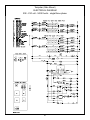
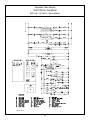
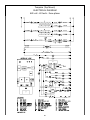
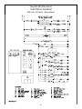
1
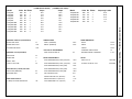
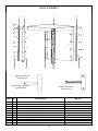
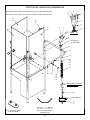
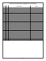
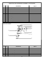
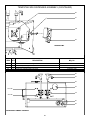
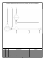
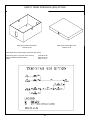
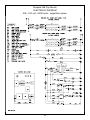
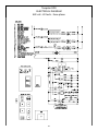
TEMPSTAR
TEMPSTAR SDS
TEMPSTAR NB
HOT WATER SANITIZING UPRIGHT
DOOR DISHMACHINES
SERVICE MANUAL
Visit Jackson on the Internet at:
www.jacksonmsc.com
March 4, 2002
P/N 7610-011-86-35 (Rev. B)
TABLE OF CONTENTS
Section
I.
Description
Page
General
Specifications of the Tempstar
Specifications of the Tempstar SDS
Specifications of the Tempstar NB
1
1
1
Instructions
Installation Instructions
Operation Instructions
2
3
III.
Troubleshooting Section
4
IV.
Drawing/Parts Section
Dimensions Tempstar/Tempstar NB(Side Mounted Control Box)
Dimensions Tempstar/Tempstar NB(Top Mounted Control Box)
Dimensions Tempstar SDS
Table Dimensions
Side Mounted Control Box Assembly
Top Mounted Control Box Assembly
SDS Control Box Assembly
Hood Assembly
Hood Assembly (Single Piece Weldment)
Cantilever Arm/Door Assemblies
Tub Front Assembly
Wash Tank Heating System
RinseTank Assembly
Inner Tub Components/Track Assembly
Wash Pump Exploded View
Wash Motors
Thermostats/Wash Heaters/Rinse Heaters
Incoming Plumbing/Outlet Plumbing Assembly
Tempstar NB Incoming Plumbing Assembly
Tempstar SDS Incoming Plumbing Assembly
Vacuum Breaker Repair Kit (3/4” NPT)
Solenoid Valve Repair Parts
Wash and Rinse Arm/Manifold Assemblies
Tempstar SDS Dispenser Assembly
Water Pressure Regulator Kit (WPRK) Option Plumbing
Safety Door Interlock (SDI) Option
Exhaust Fan Control Option
460 Volt Transformer Mounting Box
6
7
8
9
10
12
14
16
17
18
20
21
22
23
24
25
26
27
29
30
31
31
32
34
39
40
41
42
Electrical Diagrams
208 - 230V, 60 Hz, single/three phase Tempstar (Side Mount)
460V, 60 Hz, three phase Tempstar (Side Mount)
208 - 230V, 60 Hz, single/three phase Tempstar (Top Mount)
460V, 60 Hz, three phase Tempstar (Top Mount)
208 - 230V, 60 Hz, single/three phase Tempstar NB (Side Mount)
460V, 60 Hz, three phase Tempstar NB (Side Mount)
208 - 230V, 60 Hz, single/three phase Tempstar NB (Top Mount)
460V, 60 Hz, three phase Tempstar NB (Top Mount)
208 - 230V, 60 Hz, single/three phase Tempstar SDS
460V, 60 Hz, three phase Tempstar SDS
Tempstar SDS Dispenser
43
44
45
46
47
48
49
50
51
52
53
II.
V.
i
Model
(14 KW Booster Heater)
Amps
Amps
68.7
75.4
42.1
45.5
21.7
68.7
75.4
42.1
45.5
21.7
75.8
83.6
46.3
50.7
24.1
75.8
83.6
46.3
50.7
24.1
Volts Hz Phase
Tempstar
Tempstar
Tempstar
Tempstar
Tempstar
Tempstar SDS
Tempstar SDS
Tempstar SDS
Tempstar SDS
Tempstar SDS
208
230
208
230
460
208
230
208
230
460
60
60
60
60
60
60
60
60
60
60
1
1
3
3
3
1
1
3
3
3
Model
Tempstar NB
Tempstar NB
Tempstar NB
Tempstar NB
Tempstar NB
Volts Hz Phase
208
230
208
230
460
60
60
60
60
60
Amperage Loads
1
1
3
3
3
24.6
26.6
16.3
17.5
7.9
PERFORMANCE/CAPABILITIES
TEMPERATURES
OPERATING CAPACITY (RACKS/HOUR)
RACKS PER HOUR
57
WASH---(MINIMUM)
DISHES PER HOUR
1425
RINSE---(MINIMUM)
GLASSES PER HOUR
1425
FRAME DIMENSIONS
150°F
WIDTH
25 3/4”
180°F
DEPTH
25 1/4”
HEIGHT
56 3/4”
STANDARD TABLE HEIGHT
34”
MAXIMUM INSIDE CLEARANCE
17 1/4”
1
ELECTRICAL REQUIREMENTS
WASH PUMP MOTOR HP
OPERATING CYCLE (SECONDS)
3/4
WASH TIME
45
RINSE TIME
11
DWELL TIME
2
INLET TEMPERATURE (12 KW) (Tempstar)
140°F
DISH 20” X 20”
OPTIONAL
TOTAL CYCLE TIME
60
INLET TEMPERATURE (14 KW) (Tempstar)
110°F
GLASS & SILVER 20” X 20”
OPTIONAL
INLET TEMPERATURE (12 KW) (SDS)
140°F
INLET TEMPERATURE (14 KW) (SDS)
110°F
TANK CAPACITY (LITERS) GALLONS
WATER REQUIREMENTS
RACKS
WASH TANK (MINIMUM)
8.0
INLET TEMPERATURE (12 KW) (NB)
180°F
BOOSTER TANK
3.0
GALLONS PER HOUR
52.0
WATER LINE SIZE I.P.S. (Minimum)
3/4”
DRAIN LINE SIZE I.P.S. (Minimum)
1-1/2”
FLOW PRESSURE P.S.I. (Optimum)
20
WASH PUMP CAPACITY
(LITERS) GALLONS PER MINUTE
150
SPECIFICATIONS for TEMPSTAR/SDS/NB
(12 KW Booster Heater)
INSTALLATION INSTRUCTIONS
Jackson MSC Inc. provides technical support for all of the dishmachines detailed in this manual. We strongly recommend that
you refer to this manual before making a call to our technical support staff. Please have this manual with you when you call so that
our staff can refer you, if necessary, to the proper page. Technical
support is available from 8:00 a.m. to 5:00 p.m. (EST), Monday
through Friday. Technical support is not available on holidays.
Contact technical support toll free at 1-888-800-5672. Please
remember that technical support is available for service personnel only.
proceeding. Install the water supply line (3/4” pipe size minimum)
to the dishmachine line strainer using copper pipe. It is recommended that a water shut-off valve be installed in the water line
between the main supply and the machine to allow access for service. The water supply line is to be capable of 25 PSI “flow” pressure at the recommended temperature indicated on the data plate.
In areas where the water pressure fluctuates or is greater than the
recommended pressure, it is suggested that a water pressure regulator be installed. The Tempstar models covered in this manual
come with water pressure regulators as standard equipment.
Please notify Jackson immediately if this component is not present on your machine.
VISUAL INSPECTION: Before installing the unit, check the container and machine for damage. A damaged container is an indicator that there may be some damage to the machine. If there is
damage to both the container and machine, do not throw away the
container. The dishmachine has been inspected and packed at
the factory and is expected to arrive to you in new, undamaged
condition. However, rough handling by carriers or others may
result in there being damage to the unit while in transit. If such a
situation occurs, do not return the unit to Jackson; instead, contact
the carrier and ask them to send a representative to the site to
inspect the damage to the unit and to complete an inspection
report. You must contact the carrier within 48 hours of receiving
the machine. Also, contact the dealer through which you purchased the unit.
Do not confuse static pressure with flow pressure. Static pressure
is the line pressure in a “no flow” condition (all valves and services
are closed). Flow pressure is the pressure in the fill line when the
fill valve is opened during the cycle.
It is also recommended that a shock absorber (not supplied with
the Tempstar model) be installed in the incoming water line. This
prevents line hammer (hydraulic shock), induced by the solenoid
valve as it operates, from causing damage to the equipment.
PLUMBING CHECK: Slowly turn on the water supply to the
machine after the incoming fill line and the drain line have been
installed. Check for any leaks and repair as required. All leaks
must be repaired prior to placing the machine in operation.
UNPACKING THE DISHMACHINE: Once the machine has been
removed from the container, ensure that there are no missing
parts from the machine. This may not be obvious at first. If it is discovered that an item is missing, contact Jackson immediately to
have the missing item shipped to you.
ELECTRICAL POWER CONNECTION: Electrical and grounding
connections must comply with the applicable portions of the
National Electrical Code ANSI/NFPA 70 (latest edition) and/or
other electrical codes.
LEVEL THE DISHMACHINE: The dishmachine is designed to
operate while being level. This is important to prevent any damage to the machine during operation and to ensure the best
results when washing ware. The unit comes with adjustable bullet
feet, which can be turned using a pair of channel locks or by hand
if the unit can be raised safely. Ensure that the unit is level from
side to side and from front to back before making any connections.
Disconnect electrical power supply and place a tag at the disconnect switch to indicate that you are working on the circuit.
The dishmachine data plate is located on the right side and to the
front of the machine. Refer to the data plate for machine operating requirements, machine voltage, total amperage load and serial number.
PLUMBING THE DISHMACHINE: All plumbing connections must
comply with all applicable local, state, and national plumbing
codes. The plumber is responsible for ensuring that the incoming
water line is thoroughly flushed prior to connecting it to any component of the dishmachine. It is necessary to remove all foreign
debris from the water line that may potentially get trapped in the
valves or cause an obstruction. Any valves that are fouled as a
result of foreign matter left in the water line, and any expenses
resulting from this fouling, are not the responsibility of the manufacturer.
To install the incoming power lines, open the control box. This will
require taking a phillipshead screwdriver and removing the four (4)
screws on the front cover of the control box. Install 3/4” conduit
into the pre-punched holes in the back of the control box. Route
power wires and connect to power block and grounding lug. Install
the service wires (L1, L2, and L3 (3 phase only)) to the appropriate terminals as they are marked on the terminal block. Install the
grounding wire into the lug provided. Tighten the connections. It is
recommended that “DE-OX” or another similar anti-oxidation
agent be used on all power connections.
CONNECTING THE DRAIN LINE: The drain for the Tempstar
models covered in this manual are gravity discharge drains. All
piping from the 1-1/2” FNPT connection on the wash tank must be
pitched (1/4” per foot) to the floor or sink drain. All piping from the
machine to the drain must be a minimum 1-1/2” I.P.S. and shall not
be reduced. There must also be an air gap between the machine
drain line and the floor sink or drain. If a grease trap is required by
code, it should have a flow capacity of 5 gallons per minute.
VOLTAGE CHECK: Ensure that the power switch is in the OFF
position and apply power to the dishmachine. Check the incoming
power at the terminal block and ensure it corresponds to the voltage listed on the data plate. If not, contact a qualified service
agency to examine the problem. Do not run the dishmachine if the
voltage is too high or too low. Shut off the service breaker and
mark it as being for the dishmachine. Advise all proper personnel
of any problems and of the location of the service breaker.
Replace the control box cover and tighten down the screws.
WATER SUPPLY CONNECTION: Ensure that you have read the
section entitled “PLUMBING THE DISHMACHINE” above before
2
OPERATION INSTRUCTIONS
PREPARATION: Before proceeding with the start-up of the unit,
verify the following:
Close the doors and the unit will start automatically. Once the
cycle is completed, open the door (again watching for the dripping
hot water) and remove the rack of clean ware. Replace with a rack
of soiled ware and close the doors. The process will then repeat
itself.
1. The pan strainer and pump suction strainer are in
place and are clean.
2. The overflow tube and o-ring are installed.
OPERATIONAL INSPECTION: Based upon usage, the pan
strainer may become clogged with soil and debris as the workday
progresses. Operators should regularly inspect the pan strainer to
ensure it has not become clogged. If the strainer does, it will
reduce the washing capability of the machine. Instruct operators
to clean out the pan strainer at regular intervals or as required by
work load.
3. That the wash and rinse arms are screwed securely
into place and that their endcaps are tight. The wash
and rinse arms should rotate freely.
POWER UP: To energize the unit, turn on the power at the service
breaker. The voltage should have been previously verified as
being correct. If not, the voltage will have to be verified.
SHUTDOWN AND CLEANING: At the end of the workday, close
the doors. When the unit completes the cycle, turn the power
switch to the OFF position and open the doors. Remove and clean
the pan strainer. Remove the drain stopper from the tub and allow
the tub to drain (NOTE: the wash tank water will be hot so caution
is advised). Once the wash tub is drained, remove the pump suction strainer. Remove soil and debris from the strainer and set to
the side. Unscrew the wash and rinse arms from their manifolds.
Remove the endcaps and flush the arms with water. Use a brush
to clean out the inside of the arms. If the nozzles appear to be
clogged, use a toothpick to remove the obstruction. Wipe the
inside of the unit out, removing all soil and scraps. Reassembly
the wash and rinse arms and replace them in the unit. The arms
only need to be hand tight, do not use tools to tighten them down.
Reinstall the drain stopper and strainers and close the doors.
FILLING THE WASH TUB: Ensure that the delime switch is in the
NORMAL position, and place the power switch into the ON position. The Tempstar should fill automatically and shut off when the
appropriate level is reached (just below the pan strainer). Verify
that the drain stopper is preventing the wash tub water from leaking excessively. There may be some slight leakage from the drain
hole. Verify that there are no other leaks on the unit before proceeding any further. The wash tub must be completely filled before
operating the wash pump to prevent damage to the component.
Once the wash tub is filled, the unit is ready for operation.
WARE PREPARATION: Proper preparation of ware will help
ensure good results and less re-washes. If not done properly,
ware may not come out clean and the efficiency of the dishmachine will be reduced. It is important to remember that a dishmachine is not a garbage disposal and that simply throwing
unscraped dishes into the machine simply defeats the purpose
altogether of washing the ware. Scraps should be removed from
ware prior to being loaded into a rack. Pre-rinsing and pre-soaking are good ideas, especially for silverware and casserole dishes. Place cups and glasses upside down in racks so that they do
not hold water during the cycle. The dishmachine is meant not
only to clean, but to sanitize as well, to destroy all of the bacteria
that could be harmful to human beings. In order to do this, ware
must be properly prepared prior to being placed in the machine.
DAILY MACHINE PREPARATION: Refer to the section entitled
“PREPARATION” at the top of this page and follow the instructions
there. Afterwards, check that all of the chemical levels are correct
and/or that there is plenty of detergent available for the expected
workload.
WARM-UP CYCLES: For a typical daily start-up, it may be necessary to run the machine through 3 cycles to ensure that all of the
cold water is out of the system and to verify that the unit is operating correctly. To cycle the machine, ensure that the power is on
and that the tub has filled to the correct level. Lift the doors and
the cycle light will illuminate. When the light goes out, close the
doors, the unit will start, run through the cycle, and shut off automatically. Repeat this two more times. The unit should now be
ready to proceed with the washing of ware.
WASHING A RACK OF WARE: To wash a rack, open the doors
completely (being careful for hot water that may drip from the
doors) and slide the rack into the unit.
3
TROUBLESHOOTING SECTION
WARNING: Inspection, testing and repair of electrical equipment should only be performed by a qualified service technician.
Many of the tests require that the unit have power to it and live electrical components be exposed. USE EXTREME CAUTION
WHEN TESTING THE MACHINE.
Problem: Dishmachine will not fill after the door is close. Power “ON” light is illuminated.
1. Faulty rinse solenoid valve. Repair or replace valve as required.
2. Faulty door switch. Verify the wiring of the switch; if correct, replace the switch.
3. Fouled/faulty high level probe. Clean probe if fouled. If clean, and still not working, replace.
Problem: Dishmachine will not fill after the door is closed. Power “ON” light is not illuminated.
1. Service breaker tripped. Reset. If the breaker trips again, contact an electrician to verify the amp draw of the machine.
2. Machine not connected to power source. Verify that the machine has been properly connected to the power source.
3. Faulty power source. Verify the wiring of the switch; if correct, replace switch.
Problem: Dishmachine will not run after the door is closed. Power “ON” light is illuminated and the unit is filling.
1. Timer motor is faulty. Verify that the timer is rotating. If not, check to see that the motor is receiving power. If so, replace the motor
and/or timer assembly.
2. Wash motor faulty/damaged. Verify that the wash motor is getting power. If so, replace the motor.
3. Wash motor contactor faulty. Check for continuity; if contacts are open, replace the contactor.
Problem: Dishmachine runs continuously in the wash cycle.
1. Machine is in Delime mode. Flip NORMAL/DELIME switch to NORMAL mode.
2. Timer motor is faulty. Verify that the timer is rotating. If not, check to see that the motor is receiving power. If so, replace the motor
and/or timer assembly.
3. Cam timer jammed by obstruction. Remove obstruction.
Problem: Wash or rinse heater does not work.
1. Faulty heater element. Check element for continuity; if open, replace the heater.
2. Faulty heater contactor. Replace the contactor.
3. Misadjusted/faulty thermostat(s). Verify operation and setting of thermostats, replace if necessary.
Problem: Dishmachine fill slowly and/or the rinse is weak.
1. Clogged or obstructed rinse arms. Remove and clean the rinse arms.
2. Low incoming water pressure. Adjust the water pressure regulator to ensure that there is 20 PSI flow.
3. Y-strainer is clogged. Clean out the Y-strainer.
Problem: Rinse water not reaching required temperature.
1. Faulty rinse heater. Check element for continuity; if open, replace heater.
2. Misadjusted/faulty thermostat(s). Verify operation and setting of thermostats, replace if necessary.
3. Rinse thermometer is defective. Replace thermometer.
Problem: Wash water is not reaching required temperature.
1. Faulty wash heater. Check element for continuity; if open, relace the heater.
2. Misadjusted/faulty thermostat(s). Verify operation and setting of thermostats, replace if necessary.
3. Wash thermometer is defective. Replace thermometer.
4
TROUBLESHOOTING SECTION
WARNING: Inspection, testing and repair of electrical equipment should only be performed by a qualified service technician.
Many of the tests require that the unit have power to it and live electrical components be exposed. USE EXTREME CAUTION
WHEN TESTING THE MACHINE.
Problem: Doors will not close completely.
1. Improper spring tension. Adjust spring tension as required by loosening (not removing) spring bolt nuts and adjusting the tension.
Tighten nuts back when done.
2. Obstruction in door channel. Remove the obstruction.
3. Doors are not square with frame. Adjust the frame to accommodate the doors.
Problem: Water leaks at the wash pump.
1. Wash pump seal defective. Replace the seal.
2. Petcock or pump drain (if equipped) not shut/tight. Close or tighten.
3. Loose hoses (hose clamps) on the wash pump. Tighten the hose clamps.
Problem: Will not rinse during autocycle.
1. Defective rinse solenoid. Repair or replace the rinse solenoid as required.
2. Faulty fill microswitch. Replace microswitch.
3. No water to the machine. Verify that there is water a 20 PSI connected to the machine.
Problem: Dishes are not coming clean.
1. Machine temperatures are not up to the minimum requirements. Verify that incoming water, rinse water, and wash water match
the required temperatures as listed on the machine data plate.
2. No detergent/too much detergent. Adjust detergent concentration as required for the amount of water held by the machine.
3. Solid dispenser canister is empty. Replace the canister.
5
DIMENSIONS TEMPSTAR/TEMPSTAR NB (SIDE MOUNTED CONTROL BOX)
A
76”
W/ DOOR
OPEN
ADJUSTABLE HEIGHT
OF 4” TO
8”. SHIPS AT 4” SPACE.
61 3/4”
WATER
INLET TO
FLOOR
17”
OPENING
34”
TABLE
HEIGHT
10 5/8”
B
D
2 7/8”
NOTE: MINIMUM
SPACE REQUIRED IS
FOR BOTH THE
BACK AND SIDES.
15 1/2”
C
14 3/8”
C
LEGEND
A- WATER INLET (3/4” IPS)
B- ELECTRICAL CONNECTION POINT
C- DRAIN (1 1/2”IPS)
D-STANDARD CLEARANCE BETWEEN
MACHINE AND WALL (WITH DISHTABLE) IS 4”.
6
DIMENSIONS TEMPSTAR/TEMPSTAR NB (TOP MOUNTED CONTROL BOX)
LEGEND
A- WATER INLET (3/4” IPS)
B- ELECTRICAL CONNECTION POINT
C- DRAIN (1 1/2”IPS)
D-STANDARD CLEARANCE BETWEEN
MACHINE AND WALL (WITH DISHTABLE) IS 4”.
D
D
4 7/8”
B
25 1/4”
32”
B
A
76”
W/ DOOR
OPEN
17”
MACHINE
OPENING
60 5/8”
64 3/8”
61 3/4”
34”
TABLE
HEIGHT
14 3/8”
DRAIN
TO
FLOOR
C
15 1/2”
7
DIMENSIONS TEMPSTAR SDS
2 7/8”
2 1/2”
D
B
2 1/2”
15 1/2”
A
25 1/4”
D
25 1/4”
32”
B
17 1/2”
OPEN
74”
60 3/4”
76”
34”
TABLE
HEIGHT
C
14”
7 1/4”
A
LEGEND
A - Drain 1 1/2” I.P.S.
B - Water inlet 3/4” I.P.S.
C - Electrical connection
D - Standard wall clearance with dishtable 4”
8
4”
MIN.
25 1/4”
20 1/2”
OPENING
2 1/2”
TABLE DIMENSIONS
TABLE DIMENSIONS
CORNER INSTALLATION
2 1/4”
20 1/2”
OPENING
4”
MIN.
25 1/4”
3/4”
1 1/2” ROLL
TABLE DIMENSIONS
CONNECTION TO DISHMACHINE
2 1/2”
20 1/2”
OPENING
25 1/4”
4”
MIN
20 1/2”
TABLE DIMENSIONS
STRAIGHT THROUGH INSTALLATION
25 1/4”
9
SIDE MOUNTED CONTROL BOX ASSEMBLY
1
2, 21
9,22
3
10, 22
11, 22
13, 14
4
5
12, 22
6
15, 16
17
7, 8
12, 22
18, 23, 24
19
CONTROL BOX FRONT COVER
INNER CONTROL BOX LAYOUT
20
Cover, Dielectric Control Panel
5700-021-50-89
21, 22
CONTROL BOX BOTTOM LAYOUT
Bracket, Side Mount Electrical Box
5700-041-65-68
THE MOUNTING SCREWS FOR THE CONTROL BOX
FRONT COVER (10-32 X 1/2” SLOTTED TRUSSHEAD
SCREWS) MAY BE ORDERED USING 5305-011-39-85.
10
SIDE MOUNTED CONTROL BOX ASSEMBLY (CONTINUED)
ITEM
QTY
DESCRIPTION
Mfg. No.
1
1
Power Switch
2
1
Cycle Counter
3
1
Normal/Delime Switch
4
1
Power Light
5
1
High Limit Light
6
1
Cycle Light
7
1
Decal, Control Box Cover
8
1
Control Box Cover
9
1
Relay, Top Mount, Control
10
1
Fuse Holder
11
1
Timer
12
2
Contactor, 220V, 4 Pole (1 for Tempstar NB models)
13
1
Liquid Level Control Board
14
2
Screw, 6-32 x 5/8" Long
15
1
Wash Motor Contactor
16
3
Screw, 10-32 x 3/8" Panhead
17
See Below
18
1
3 Pole Terminal Block
19
1
Control Box Weldment
20
See Below
21
See Below
22
9
Screw, 6-32 x 3/8" Long
23
3
Locknut, 10-24 with Nylon Insert
24
1
Ground Lug
Other components not shown:
Connector, 1/2”, 90 DEG Plastic
5975-011-45-14
Connector, 3/4”, 45 DEG Plastic
5975-011-47-74
Connector, 1/2”, 45 DEG Plastic
5975-011-45-23
Connector, 1/2”, 90 DEG Metal
5975-111-01-00
Grommet, 1/2” OD x 3/8” ID
5325-011-46-73
Grommet, 7/8” Split
5975-200-40-00
Plug
5975-011-47-81
Decal, Delime/Normal
9905-011-34-96
Decal, L1, L2, L3
9905-101-12-66
Decal, Copper Conductors
9905-011-47-35
Decal, Ground
9905-011-86-86
5930-301-21-18
5990-111-47-42
5930-301-46-00
5945-504-06-18
5945-504-07-18
5945-504-08-18
9905-021-64-41
5700-031-91-45
5945-111-47-51
5920-401-03-14
5945-303-31-00
5945-109-01-69
6680-200-08-21
5305-011-39-85
5945-109-03-69
5305-173-26-00
N/A
5940-011-48-27
5700-041-47-55
N/A
N/A
5305-171-02-00
5310-373-01-00
5940-200-76-00
The following components are used only in the 460 Volt control box.
Item #20
Circuit Breaker, 2 AMP
5925-111-64-18
Item #21
Transformer
5950-111-65-93
Exchange item #15 with the
following:
Wash Motor Contactor
5945-002-14-78
Item #17
Overload (not shown)
5945-002-14-79
11
TOP MOUNTED CONTROL BOX ASSEMBLY
21
20
1
19
2
3
18
4
17
16
5
15
6
7
8
9
10
11
12
12
13
14
TOP MOUNTED CONTROL BOX ASSEMBLY (CONTINUED)
ITEM
QTY
1
2
3
4
5
6
7
8
9
10
11
12
13
14
15
16
17
18
19
20
21
1
1
1
1
1
1
1
1
1
1
1
1
1
1
1
1
1
2
1
1
1
DESCRIPTION
Mfg. No.
Control Box Weldement
Ground Lug
Terminal Block
Contactor, Wash Motor 208-230
Relay
Counter
Plate, Counter Mounting
Decal, Control Box
Light, Yellow
Light, Green
Light, Red
Temperature Gauge, Wash 96" Lead
Temperature Gauge, Rinse 48" Lead
Switch, Power
Timer
Liquid Level Control Board
Bracket, Liquid Level Control Board
Heater Contactors
Magnetic Reed Switch
Normal Delime Switch
Fuse Holder
5700-002-29-76
5940-200-76-00
5940-011-48-27
5945-109-03-69
5945-111-47-51
5990-111-47-42
5700-002-37-71
9905-002-31-85
5945-111-44-44
5945-111-44-43
5945-111-44-45
6685-111-68-48
6685-111-68-49
5930-002-29-13
5945-303-31-00
6680-200-08-21
5700-002-13-22
5945-109-01-69
5930-011-47-50
5930-301-21-18
5920-401-03-14
For a 460 Volt control box, exchange item 4 with one each of the following:
Wash Motor Contactor
5945-002-14-78
Overload
5945-002-14-79
Other components not shown:
Cover, Top Mount Control Box
Decal, Warning-Disconnect Power
Screw, 10-32 x 3/8” Phillips Truss Head
5700-002-23-03
9905-100-75-93
5305-173-12-00
Leg, Control Box
Screw, 1/4”-20 x 2 3/4” Hex Head Cap
Washer, 1/4”-20 ID S/S
Locknut, 1/4”-20 S/S Hex w/Nylon Insert
5700-002-33-05
5305-274-13-00
5311-174-01-00
5310-374-01-00
Connector, 1/2”, 90 DEG Plastic
Connector, 3/4”, 45 DEG Plastic
Connector, 1/2”, 45 DEG Plastic
Connector, 1/2”, 90 DEG Metal
Grommet, 1/2” OD x 3/8” ID
Grommet, 7/8” Split
Plug, 1/2”
Decal, Delime/Normal
Decal, L1, L2, L3
Decal, Copper Conductors
Decal, Ground
5975-011-45-14
5975-011-47-74
5975-011-45-23
5975-111-01-00
5325-011-46-73
5975-200-40-00
5975-011-47-81
9905-011-34-96
9905-101-12-66
9905-011-47-35
9905-011-86-86
Associated Hardware:
Locknut, 6-32 S/S Hex w/Nylon Insert
Locknut, 10-24 S/S Hex w/Nylon Insert
Screw, 6-32 x 5/8”
Screw, 6-32 x 3/8” Phillips Round Head
5310-373-03-00
5310-373-01-00
5305-011-39-85
5305-171-02-00
13
SDS SIDE MOUNTED CONTROL BOX ASSEMBLY
12
8
16
13
7
17
6
18
9
15
14
10
5
11
4
19
3
22
20
1
2
23
21
Cover, Dielectric Control Panel
5700-021-50-89
24
Bracket, Side Mount Electrical Box
5700-041-65-68
27
25
26
14
SDS SIDE MOUNTED CONTROL BOX ASSEMBLY (CONTINUED)
ITEM
QTY
DESCRIPTION
Mfg. No.
1
1
Control Box Cover Weldment
2
1
Decal, Control Box Cover
3
1
Light, Amber
4
1
Light, Green
5
1
Light, Red
6
1
Manual Wash Switch
7
2
Screw, 4-40 x 1/4" Phillips Panhead
8
1
Cycle Counter
9
1
Wash Switch
10
4
Screw, 10-32 x 3/8" Phillips Panhead
1
Cover, Electrical Box Panel
11
1
Frame, Electrical Box Cover Panel
12
1
Board, PC Rinse
13
1
Board, PC Detergent
14
15
8
Screw, 6-32 x 3/8" Long
1
Bracket, PC Board
16
4
Lockwasher, Internal Tooth #10
17
18
4
Locknut, 10-24 with Nylon Insert
19
1
Control Box Weldment
20
2
Relay, Top Mount, Control
21
2
Contactor, 220V, 4 Pole (1 for Tempstar NB models)
22
1
Timer
23
1
Liquid Level Control Board
24
1
Contactor, 220V, 2 Pole
25
1
Transformer
26
1
Ground Lug
27
1
3 Pole Terminal Block
Other components not shown:
Connector, 1/2”, 90 DEG Plastic
5975-011-45-14
Connector, 3/4”, 45 DEG Plastic
5975-011-47-74
Connector, 1/2”, 45 DEG Plastic
5975-011-45-23
Connector, 1/2”, 90 DEG Metal
5975-111-01-00
Grommet, 1/2” OD x 3/8” ID
5325-011-46-73
Grommet, 7/8” Split
5975-200-40-00
Plug, 1/2”
5975-011-47-81
Decal, Delime/Normal
9905-011-34-96
Decal, L1, L2, L3
9905-101-12-66
Decal, Copper Conductors
9905-011-47-35
Decal, Ground
9905-011-86-86
The following components are used only in the 460 Volt control box.
Exchange item number 25
with the following:
Transformer
5950-111-65-93
Circuit Breaker, 2 AMP
5925-111-64-18
Fuse Holder
5940-401-03-14
15
5700-021-60-43
9905-021-50-13
5945-504-06-18
5945-504-08-18
5945-504-07-18
5930-301-46-00
5305-011-36-92
5990-111-47-42
5930-301-21-18
5305-173-04-00
5700-011-49-23
5700-011-49-22
6680-111-50-55
6680-111-50-54
5305-171-02-00
5700-011-49-24
5311-011-59-51
5310-373-01-00
5700-041-47-55
5945-111-47-51
5945-109-01-69
5945-303-31-00
6680-200-08-21
5945-109-03-69
5950-400-01-35
5940-200-76-00
5940-011-48-27
Exchange item number
24 with the following:
Wash Motor Contactor
5945-002-14-78
Overload (not shown)
5945-002-14-79
HOOD ASSEMBLY
4
8
2
6
1
3, 5
7
9
10
Switch Box Weldment
5700-002-14-34
SDS Switch Box Weldment
5700-002-30-98
ITEM
QTY
1
1
2
3
4
5
6
7
8
9
10
1
1
1
1
1
1
1
1
28
28
28
Magnetic Reed Switch
5930-011-47-50
DESCRIPTION
Mfg. No.
Hood Weldment (Tempstar/Tempstar NB)
Hood Weldment (Tempstar SDS only)
Left Front Hood Support
Right Front Hood Support
Double Door Guide, Front Left
Double Door Guide, Front Right
Guide, Right Rear
Guide, Left Rear
Screw, 1/4"-20 x 1/2" Long
Locknut, 1/4"-20 with Nylon Insert
Washer, 1/4"-20 ID, S/S, Flat
5700-041-94-39
5700-041-47-87
5700-021-33-18
5700-021-33-17
5700-021-33-20
5700-021-33-19
5700-021-84-70
5700-021-84-71
5305-274-02-00
5310-374-01-00
5311-174-01-00
16
HOOD ASSEMBLY (SINGLE PIECE WELDMENT)
1
3
2
Switch Box Weldment
5700-002-14-34
SDS Switch Box Weldment
5700-002-30-98
ITEM
QTY
1
1
2
3
1
1
1
1
Magnetic Reed Switch
5930-011-47-50
DESCRIPTION
Mfg. No.
Hood Weldment (Tempstar /Tempstar NB)
Hood Weldment (Tempstar SDS)
Plug, Bulkhead
Frame Weldment
5700-002-29-79
5700-002-36-91
4730-609-05-00
5700-031-48-01
17
CANTILEVER ARM/DOOR ASSEMBLIES
Back Corner Steam Plugs may be ordered using part number 5700-002-25-01.
4
5
6
5
7
Front Corner Steam Plugs may be ordered using part number 5700-002-24-99.
28
27
30
31
8
9
*2
29
27
26
27
1
10
Detail “A”
3
See Detail “A”
for parts detail.
11
12
13
18
19
20
21
14
25
24
22
23
21
22
MOUNTING OF SPRING
TO BOTTOM RAIL
15
BOTTOM RAIL
16
17
Door Connecting Plate
5700-002-20-78
Door Connecting Bracket
5700-021-33-39
18
CANTILEVER ARM/DOOR ASSEMBLIES (CONTINUED)
ITEM
QTY
1
2
3
4
5
6
7
8
9
10
11
12
13
14
15
16
17
18
19
20
21
22
23
24
25
26
26A
27
28
28a
29
29A
30
31
2
6
2
2
4
2
2
2
2
2
2
1
2
2
2
2
4
2
4
2
4
2
2
2
2
1
1
6
1
1
1
1
1
2
DESCRIPTION
Mfg. No.
Bracket, Cantilever Support
Wear Button .50 Dia
Yoke Assembly
Clevis Pin
Washer, Nylon
Bushing
Cotter Pin 3/32" x 3/4"
Yoke
Space Washer
Nut, 3/8"-16 S/S Hex Locking
Spring Pin, 1/4" x 1 1/8"
Cantilever Arm
Rod, Spring
Spring
Bolt, Canlilever Hanger Eye 3/8"-16
Washer, 3/8" ID x 7/8" OD S/S
Nut, 3/8"-16 S/S Hex
Screw, 1/4"-20 x 3/4" Lg. S/S
Washer, 1/4" Stainless Steel
Spacer, PB Bolt
Locknut, 1/4"-20 S/S Hex w/Nylon Insert
Screw 1/4"-20 x 1 1/2" lg stainless Steel
Sleeve, Cantilever Arm
Connector, Cantilever Arm
Cantilever Arm Plug
Door, Front (Complete Assembly)
Door Only, Front
Door, Guides
Door, Left Side (Complete Assembly)
Door Only, Left Side
Door, Right Side (Complete Assembly)
Right Door Weldment with Studs
Magnet, Reed Switch
Locknut, 8-32 S/S Hex w/Nylon Insert
5700-031-88-00
5700-011-88-01
5700-000-75-77
5315-700-01-00
5311-369-03-00
3120-100-03-00
5315-207-01-00
5700-000-75-78
5311-156-02-00
5310-256-04-00
5315-407-06-00
5700-031-50-67
5700-002-29-38
5340-109-02-00
5306-956-05-00
5311-176-01-00
5310-276-01-00
5305-274-04-00
5311-174-01-00
5700-000-29-40
5310-374-01-00
5305-274-23-00
5700-000-85-69
5700-011-90-99
5340-011-35-00
5700-002-30-89
5700-002-29-83
5700-111-33-59
5700-002-30-87
5700-002-29-86
5700-002-30-88
5700-002-29-85
5930-111-51-68
5310-272-02-00
19
TUB FRONT ASSEMBLY
1, 2, 3
4
10
24
11
7
9
6
8
23
12
19
13, 14
16, 18
25
14, 15
17, 18
*27
*26
SEE PAGE
ENTITLED
“WASH
MOTORS”.
20
21, 22
SEE PAGE ENTITLED
“WASH/RINSE HEATERS”.
* Represents an
item not shown.
5
Nut, 1/4”-20 Serrated Nut
5310-011-66-49
Pump Support Main Bracket Weldment
5700-021-66-47
Pump Support Adjustable Bracket
5700-002-20-41
Pump Support Bracket Complete Assembly
5700-002-00-46.
20
TUB FRONT ASSEMBLY (CONTINUED)/WASH TANK HEATING SYSTEM
ITEM
QTY
1
2
3
4
5
6
7
8
9
10
11
12
13
14
15
16
17
18
19
20
21
22
23
24
25
*26
*27
8
8
8
1
4
1
2
1
1
1
2
1
1
2
1
1
1
4
1
1
4
4
1
1
1
1
1
DESCRIPTION
Mfg. No.
Screw, 1/4"-20 x 1/2" Long
Locknut, 1/4"-20 with Nylon Insert
Washer, 1/4"-20 ID, S/S, Flat
Frame Weldment
Bullet Foot
Discharge Hose
Hose Clamp
Gauge Bracket (Side Mount Control Box Only)
Thermometer, Wash (Side Mount Control Box Only)
Thermometer, Rinse (Side Mount Control Box Only)
Locknut, 10-24 with Nylon Insert
Decal, Gauge Bracket (Side Mount Control Box Only)
Thermostat, High Limit
Thermostat Bracket
Thermostat, Regulating
Decal, High Limit
Decal, Thermostat Regulating
Locknut, 6-32 with Nylon Insert
Fitting, 1/4" Imperial Brass
Wash Heater Gasket
Lockwasher, 5/16", S/S, Split
Nut, Hex, 5/16"18, S/S
Probe, High Water
Lower Wash Manifold Weldment
Nipple
Clamp, Hose 5 5/8" to 6"
Clamp, 1/8" Nylon
5305-274-02-00
5310-374-02-00
5311-174-01-00
5700-031-48-01
5340-108-01-03
5700-011-88-24
4730-719-01-37
5700-011-48-08
6685-111-40-38
6685-111-40-39
5310-373-01-00
9905-011-50-88
5930-121-71-36
5700-011-73-72
5930-121-67-72
9905-011-84-32
9905-011-84-31
5310-373-03-00
5310-924-02-05
5330-011-47-79
5311-275-01-00
5310-275-01-00
6680-200-02-68
5700-031-46-00
5700-021-34-84
4730-011-34-90
5975-601-10-15
WASH TANK HEATING SYSTEM EXPLANATION
The wash tank heater system is electrically connected in the circuit so that it is dependent upon the dishwasher being properly filled
with and maintaining a safe water level. The system is made up of two thermostats (mounted in the junction box behind the front panel),
a water level probe (mounted in the wash tank), the wash heater contactor (mounted in the control box), and the wash heater itself.
Once the water level control (WL) senses water contact (conductivity) through the water level probe (HP), it energizes the wash heater
contactor (R2). This closes the contacts to the wash heater (H2) to provide energy to heat the water in the tank.
The wash heater thermostat (TS2), which senses water temperature through a capillary bulb in the tank, will maintain tank temperature. When the water temperature reaches 155 degrees F. an N. C. contact in the thermostat opens which de-energizes the wash
heater contactor (R2). This shuts down the wash tank heater (H2).
When the water temperature falls below 150 degrees F. the contacts in the thermostat will close and the the wash tank heater (H2) will
energize to maintain the water temperature at 155 degrees nominal.
The high limit thermostat (HTLS) with a direct sensing probe prevents damage to the wash tank heater due to over-temperature conditions. Should the wash tank heater (H2) reach a temperature of 210 degrees F., a N.C. contact in the high limit thermostat (HLTS)
opens which de-energizes he wash heater contactor (R2). This shuts down the wash tank heater (H2). When this occurs the heater
overload light (E2, amber) will come on to indicate a temperature problem.
Once the dishwasher has been filled to the correct level, the wash tank heater should operate automatically.
21
RINSE TANK ASSEMBLY
2
4, 5, 6, 13
SEE PAGE ENTITLED
“WASH/RINSE HEATERS”.
1
12
3
ITEM
QTY
1
2
3
4
5
6
7
8
9
10
11
12
13
4
4
1
1
1
1
6
1
1
1
6
1
1
DESCRIPTION
7, 11
8
9, 10
Mfg. No.
Locknut, 1/4"-20 with Nylon Insert
Washer, 1/4" ID, S/S, Flat
Booster Tank Weldment
Fitting, 1/4" Imperial Brass
Thermostat Bracket
Thermostat, Rinse
Nut, Hex, 5/16"-18
Locknut, 10-24 with Nylon Insert
Decal, Warning - Disconnect Power
Booster Tank Cover Weldment
Lock Washer, 5/16", Split
Gasket, Rinse Heater
Decal, Thermostat Regulating
5310-374-01-00
5311-174-01-00
5700-001-22-02
5310-924-02-05
5700-011-73-72
5930-121-71-29
5310-275-01-00
5310-373-01-00
9905-100-75-93
5700-001-29-30
5311-275-01-00
5330-200-02-70
9905-011-84-31
22
INNER TUB COMPONENTS/TRACK ASSEMBLY
Suction Strain Weldment
5700-001-22-23
Overflow Support Bracket
5700-001-27-55
Suction Strain Bracket
5700-001-22-24
O-Ring
5330-400-05-00
Strainer Weldment
5700-021-50-07
Wash Overflow Weldment
5700-001-25-69
Rack Guide
5700-001-28-19
Rack Weldment
5700-002-01-01
Screw, 10-24 x 1/2” Long
5305-173-18-00
Locknut, 10-24 w/ Nylon Insert
5310-373-01-00
23
WASH PUMP EXPLODED VIEW
REPLACEMENT MOTORS ARE AVAILABLE
FOR PURCHASE. CONTACT JACKSON MSC
DIRECTLY TO ENSURE THAT YOU ORDER
THE CORRECT MOTOR FOR YOUR MODEL.
Casing Gasket
5330-002-00-31
Mechanical Seal
5330-002-06-21
Impeller
5700-002-01-08
24
WASH MOTORS
The Tempstar models covered in this manual come supplied with various wash motor assemblies (a wash motor assembly includes
the wash motor and the pump end), depending on the characteristics of the machine. To ensure that you order the correct wash
motor assembly for the model you are servicing, please refer to the following table:
Model
Volts
Hz
Phase
Wash Motor Assembly
Tempstar
Tempstar
Tempstar
Tempstar
Tempstar
208
230
208
230
460
60
60
60
60
60
1
1
3
3
3
6105-121-35-18
6105-121-35-18
6105-121-35-18
6105-121-35-18
6105-121-64-21
Tempstar
Tempstar
Tempstar
Tempstar
Tempstar
SDS
SDS
SDS
SDS
SDS
208
230
208
230
460
60
60
60
60
60
1
1
3
3
3
6105-121-35-18
6105-121-35-18
6105-121-35-18
6105-121-35-18
6105-121-64-21
Tempstar
Tempstar
Tempstar
Tempstar
Tempstar
NB
NB
NB
NB
NB
208
230
208
230
460
60
60
60
60
60
1
1
3
3
3
6105-121-35-18
6105-121-35-18
6105-121-35-18
6105-121-35-18
6105-121-64-21
Important note: When servicing a wash motor, it
is important to refer to the wiring schematic found
on the motor, to ensure that the motor is wired correctly. Different manufacturers of motors may not
use the same wire color codes and therefore, your
new motor, which may have been built by someone
different than who built your original motor, may not
connect using the same wires. Always refer to the
wiring diagrams on the motor you are installing. If
the motor you are installing has had the schematic
removed, contact Jackson MSC immediately for
technical support.
Details concerning the Tempstar models wash motor assemblies:
The pumps for the Tempstar models covered in this manual are close coupled centrifugal pumps. The pump casings are made from
iron and may be prone to oxidation if still water is left in the casing for an extended amount of time. It is recommended that if the unit
is not to be used for such a period, such as for renovation of the installation site, that the casing be drained completely. The impeller
is made from stainless steel to resist corrosion and is threaded onto the pump shaft. Water is prevented from travelling down the shaft
into the motor by use of a mechanical-type shaft seal. As with all mechanical seals, care must be taken not to damage the sealing surfaces. Mechanical seals should only be replaced by trained service personnel.
The motors chosen to be used on the Tempstar models covered in this manual all have open drip proof construction and are rated with
jet pump service factors for continuous duty operation. The motors are all 3/4 HP, 60 Hz, and operate at 3450 RPM.
All motors installed on Tempstar dishmachines have overload protection. Single phase motors will have built-in overload protection and
will be capacitor start units. Three phase motors will have external overload protection located in the control box. The overload protection is to protect the motor from over current damage due to electrical or mechanical failure.
It is of vital importance that it be stressed that efficient operation of the wash motor assembly is essential in proper ware washing. The
pump must never be ran without water in the casing, for this causes a build-up of heat which can damage the casing gasket and cause
the pump to leak. A leaking pump will cause the water level to lower in the machine and will have two detrimental effects: (1) air will be
pumped through the wash arms, reducing the dishmachine’s ability to wash, and (2) the liquid level control circuit will energize more
often, using more water to maintain wash tank level; this will increase the overall cost of operating the unit.
25
THERMOSTATS/WASH HEATERS/RINSE HEATERS
This unit has a probe-direct sensing type thermostat with fixed set point and adjustable range for both wash and booster tank heat regulating. The same type thermostat is used as the high limit sensor for the wash tank heater. It operates a precision single double throw
switch through a lever for close tolerance narrow differential switching capability. The unit has screw driver adjustment and front connect terminals and is mounted by 7/16”-24 thread, Loxit fitting for easy removability and serviceability. The thermostat range is from
140°F to 240°F with a maximum bulb exposure temperature of 300°F. Unit is listed at 12.5 amps at 24/120 VAC.
There are three (3) thermostats on the dishwasher. One monitors the wash tank temperature, the second monitors the rinse water temperature with the third protecting the heater element. Although all are identical in appearance there are different replacement part numbers depending on the function of the thermostat.
Calibration:
The hi-limit thermostat is used to protect the heater element in the event of a run away regulating thermostat or a dry fire situation. It
is set for 210°F +0 or -10°F with a fixed set point. This part is not adjustable.
The wash tank regulating thermostat will maintain the correct wash water temperature to meet NSF requirements. These specify that
the wash be no lower than 150°F. It is set at the factory to energize the tank heater at 155°F and de-energize at 167°F.
The rinse tank regulating thermostat will maintain the correct rinse water temperature to meet NSF requirements. It is factory set to
energize the rinse tank heater at 195°F and de-energize at 200°F.
To order the thermostats:
Thermostat, High Limit
Thermostat, Wash Tank
Thermostat, Rinse Tank
5930-121-71-36
5930-121-67-72
5930-121-71-29
To convert from the old style “bayonette” thermostats, you will
need these kits:
Kit, Thermostat, High Limit with Bracket
6401-021-83-86
Kit, Thermostat, Wash Tank with Bracket
6401-021-83-90
Kit, Thermostat, Rinse Tank with Bracket
6401-021-83-83
The Tempstar models covered in this manual come supplied with various heaters, depending on the characteristics of the machine. To
ensure that you order the correct heater for the model you are servicing, please refer to the following table:
40°F Rise
Rinse Heater (12 KW)
70°F Rise
Rinse Heater (14 KW)
Model
Volts
Hz
Phase
Tempstar
Tempstar
Tempstar
Tempstar
Tempstar
208
230
208
230
460
60
60
60
60
60
1
1
3
3
3
4540-121-47-39
4540-121-47-39
4540-121-47-39
4540-121-47-39
4540-121-65-99
4540-121-47-40
4540-121-47-40
4540-121-47-40
4540-121-47-40
4540-100-01-15
4540-121-63-38
4540-121-63-38
4540-121-63-38
4540-121-63-38
4540-121-63-39
4540-121-47-40
4540-121-47-40
4540-121-47-40
4540-121-47-40
4540-100-01-15
4540-121-63-38
4540-121-63-38
4540-121-63-38
4540-121-63-38
4540-121-63-39
Wash Heater
Tempstar
Tempstar
Tempstar
Tempstar
Tempstar
SDS
SDS
SDS
SDS
SDS
208
230
208
230
460
60
60
60
60
60
1
1
3
3
3
4540-121-47-39
4540-121-47-39
4540-121-47-39
4540-121-47-39
4540-121-65-99
Tempstar
Tempstar
Tempstar
Tempstar
Tempstar
NB
NB
NB
NB
NB
208
230
208
230
460
60
60
60
60
60
1
1
3
3
3
4540-121-47-39
4540-121-47-39
4540-121-47-39
4540-121-47-39
4540-121-65-99
26
INCOMING PLUMBING/OUTLET PLUMBING ASSEMBLY
INCOMING PLUMBING
OUTLET PLUMBING
3
2
7
15
1
8
4
9
9
10
6
10
4
5
4
16
11
10
13
14
13
10
12
17
9
12
18
When servicing plumbing components, take care not to damage the threads of each individual item. Damaged threads can cause leaks
and loss of pressure, which could adversely effect the performance of the Tempstar dishmachine. It is strongly recommended that teflon
thread tape, used in conservative amounts, be applied to threads when joining components together. It is not advised to use thread
sealing compounds, sometimes referred to as “pipe dope”. Compounds can be ejected from the threads during the tightening process
and become lodged in key components, thereby rendering them useless. Some of the components include the solenoid valve and the
pressure gauge isolation ball valve.
27
INCOMING PLUMBING/OUTLET PLUMBING ASSEMBLY
ITEM
QTY
1
2
3
4
5
6
7
8
9
10
11
12
13
14
15
16
17
18
1
1
1
2
1
1
1
1
3
6
1
2
2
1
1
1
1
1
DESCRIPTION
Mfg. No.
Water Pressure Regulator, 3/4" NPT
Valve, Ball, 1/4" NPT
Gauge, Pressure, 0-100 PSI
Nipple, Close, 3/4" NPT
Tee, Brass, 3/4" NPT x 3/4" NPT x 1/4" NPT
Valve, Solenoid, 3/4" NPT
Nipple, Brass, 3/4" NPT x 2" Long
Elbow, 3/4" NPT, Brass, Street
Union, 3/4" NPT, Brass
Adapter, 3/4" Male
Tube, Copper, 3/4" x 36 1/4" Long
Elbow, 3/4" - 90 Degree, #707 Copper
Adapter, 3/4", 604-2
Tube, Copper, 3/4" x 3 3/4" Long
Vacuum Breaker, 3/4" NPT
Tube, Copper, 3/4" x 30 3/4" Long
Elbow, 3/4" NPT,90 DEG Brass
Tube, Copper, 3/4" x 2 7/8" Long
6685-011-58-22
4810-011-72-67
6685-111-88-34
4730-207-34-00
4730-211-04-00
4810-100-03-18
4730-207-46-00
4730-206-04-34
4730-212-05-00
4730-401-11-01
5700-011-58-26
4730-406-16-01
4730-401-10-01
5700-011-58-28
4820-300-08-00
5700-011-82-28
4730-206-13-00
5700-011-76-76
28
TEMPSTAR NB INCOMING PLUMBING ASSEMBLY
1
8
2
ITEM
QTY
1
2
3
4
5
6
7
8
9
10
1
1
1
1
3
1
1
1
1
1
3
4
5
5
6
DESCRIPTION
7
9
10
5
Mfg. No.
Vacuum Breaker, 3/4" NPT
Elbow, Brass, Street, 3/4" NPT
Nipple, Brass, 3/4" NPT x 3"
Union, Brass, 3/4" NPT
Nipple, Close, Brass, 3/4" NPT
Valve, Solenoid, 3/4" NPT
Tee, Brass, 3/4" NPT x 3/4" NPT x 1/4" NPT
Pressure Gauge, 0-100 PSI
Valve, Ball, Bronze, 1/4" NPT
Water Pressure Regulator
4820-300-08-00
4730-206-04-34
4730-011-38-29
4730-212-05-00
4730-207-34-00
4810-100-03-18
4730-211-04-00
6685-111-59-66
4810-011-72-67
6685-011-58-22
29
TEMPSTAR SDS INCOMING PLUMBING ASSEMBLY
5
Please refer to the Incoming Plumbing Assembly, component numbers 7 through 14 for the components to connect
to the Booster Tank.
1
2
3
4
8
7
6
9
ITEM
QTY
1
2
3
4
5
6
7
8
9
10
11
12
1
1
1
2
1
1
1
1
1
2
1
1
10
11
DESCRIPTION
10
12
Mfg. No.
Gauge, Pressure, 0-100 PSI
Valve, Ball, 1/4" NPT
Tee, 1/4" x 1/4" x 1/4" Brass
Nipple, 1/4" Close Brass
Regulator, Pressure
Gauge, Pressure, 0-100 PSI 1/8"
Reducer, 1/4" Male x 3/8" Female Brass
Fitting, 3/8" Y-Branch
Valve, Solenoid, 3/4" NPT
Nipple, Close, 3/4" NPT
Tee, Brass, 3/4" NPT x 3/4" NPT x 1/4" NPT
Water Pressure Regulator, 3/4" NPT
6685-111-88-34
4810-011-72-67
4730-011-51-20
4730-207-02-00
6685-111-48-54
6685-011-48-32
4730-011-59-40
4730-111-58-21
4810-100-03-18
4730-207-34-00
4730-211-04-00
6685-011-58-22
30
3/4” SOLENOID VALVE & 3/4” NPT VACUUM BREAKER REPAIR PARTS KITS
Screw
Data Plate
Cap Screw
Coil & Housing
Data Plate
Valve Bonnet
Spring position is moved
for clarity.
Goes below the plunger.
Spring
4810-200-04-18
Cap
Plunger
4810-200-04-18
O-Ring
4810-100-10-18
Cap Retainer
Diaphragm
Retainer
O-Ring
Diaphragm
4810-100-10-18
Plunger
COMPONENTS
OF REPAIR KIT
4820-001-60-57
Screen
Retainer
Body
Mesh Screen
Valve Body
Complete Vacuum Breaker Assembly
Mfg. No.: 4820-300-08-00
Complete 220 Volt Solenoid Valve Assembly
Mfg. No.: 4810-100-03-18
Coil & Housing only
Mfg. No.: 4810-200-02-18
31
WASH & RINSE ARM/MANIFOLD ASSEMBLIES
10
18
13
11
10
14
12
15
14
10
15
13
Rinse Injector Weldment
1 per machine
5700-021-47-65
11
12
Plug, 1/8” NPT, Brass
3 per Rinse Injector
4730-209-07-37
10
DETAIL “A”
FINAL RINSE ARMS & MANIFOLD
Rinse Injector Gasket
2 per machine
5330-111-42-81
2, 3, 4
5
5
1
1
17
7
9, 17
6, 10
7
9, 17
9
16, 8
17
5
5
16
2, 3, 19
DETAIL “B”
WASH ARMS & MANIFOLD
32
WASH & RINSE ARM/MANIFOLD ASSEMBLIES (CONTINUED)
ITEM
QTY
1
2
3
4
5
6
7
8
9
10
11
12
13
14
15
16
17
17a
17b
17c
17d
17e
17f
18
19
1
4
4
2
2
1
1
2
2
5
2
4
2
2
4
1
2
1
1
1
1
15
20
1
2
DESCRIPTION
Mfg. No.
Upper Manifold
Nut, 3/8"-16 S/S Hex
Lockwasher 3/8
Bolt, Hex 3/8-16 x 7/8" lg
O Ring
Positioning Bracket, Manifold Tube
Tube, Wash Manifold
Gasket, Manifold
Wash Arm
Locknut, 1/4"-20 S/S Hex w/Nylon Insert
Clip, Retaining, Rinse Head Bushing
Rinse Arm Washer
Bushing, Rinse Head
Rinse Arm
Plug, Rinse Arm, Stainless Steel
Lower Wash Manifold
Bearing Assembly
Hub Nut
Hub Bushing
Hub Spindle
Ring, Retainer
3/16" Stainless Steel Ball
1/8" Stainless Steel Ball
Rinse Manifold Assembly
Bolt, Hex 3/8-16 x 1 1/4" lg
5700-031-34-82
5310-276-01-00
5311-276-01-00
5306-011-36-95
5330-111-35-15
5700-011-34-63
5700-131-15-07
5700-111-35-03
5700-021-35-93
5310-374-01-00
5340-112-01-11
5330-011-42-10
5700-021-33-84
5700-031-88-86
4730-111-60-41
5700-031-46-00
5700-021-35-97
5700-011-35-94
5700-011-35-96
5700-011-35-95
5340-011-37-81
3120-100-02-00
3120-011-37-82
5700-021-47-61
5305-276-10-00
9
EXPLODED VIEW OF
ITEM 17
17c
17a
17b
17f
17d
17e
1 or 16
33
TEMPSTAR SDS DISPENSER ASSEMBLY
1
2
3
4
SEE SECTION ENTITLED
“DISPENSER PLUMBING
ASSEMBLY”.
5
1
SEE SECTION ENTITLED
“CAM HOLDER ASSEMBLY”
6
7
9
8
10
11
SEE SECTION ENTITLED
“FEEDER PUMP”.
12
13
15
14
SEE SECTION “LOWER
DISPENSER ASSEMBLY”.
16
34
TEMPSTAR SDS DISPENSER ASSEMBLY (CONTINUED)
ITEM
QTY
1
2
3
4
5
6
7
8
9
10
11
12
13
14
15
16
3
1
1
1
1
1
1
1
1
1
1
1
3
1
1
1
DESCRIPTION
Mfg. No.
Screw, 6-32 x 3/4" Long
Lockwasher, #6, External Tooth
Rinse Cylinder Bracket
Rinse Additive Screen
Rinse Cylinder Cover
Rinse Additive Cylinder
Decal, Rinse Additive
Rinse Aid Nozzle
Detergent Screen
Detergent Spray Nozzle
Detergent Flush Pipe
Decal, Detergent Additive
Light, Red
Motor, Feeder Pump
Dispenser Molding
Sonalert
5305-171-07-00
5311-271-02-00
5700-011-59-72
5930-011-48-66
9515-011-49-01
9515-031-49-00
9905-011-59-80
4730-011-50-03
5335-011-48-65
4730-011-50-04
5700-011-51-52
9905-011-59-79
5945-011-48-96
6105-111-51-02
9515-031-48-62
5945-011-48-97
CAM HOLDER ASSEMBLY
17
18
19
20
22
21
23
24
25
ITEM
QTY
17
18
19
20
21
22
23
24
25
2
1
1
1
1
1
1
1
2
DESCRIPTION
Mfg. No.
Locknut, 4-40
Lockwasher, 4-40
Screw, 4-40 x 3/4" Long
Spring, .023 Wire
Magnet, 3/16" x 1" Long Bar
Holder, Cam Magnet
Cam Holder
Switch, 5A
Screw, 4-40 x 3/8" Long
5310-279-06-00
5311-011-59-71
5305-011-59-64
5340-111-58-02
5930-011-48-81
5340-011-48-80
5340-011-59-62
5930-011-48-83
5305-011-59-70
35
TEMPSTAR SDS DISPENSER ASSEMBLY (CONTINUED)
26
27
28
29
FEEDER PUMP
ITEM
QTY
26
27
28
29
1
1
1
2
DESCRIPTION
Mfg. No.
Plate, Solenoid Valve Mounting
Plate, Pump Mounting
Peristaltic Pump
Ferrule Nut, Chemical Tube Connector
5700-031-58-16
5700-011-57-88
4320-111-51-03
4730-609-16-00
30
31
32
33
37 & 38
34
37 & 38
35
36
DISPENSER PLUMBING ASSEMBLY
36
TEMPSTAR SDS DISPENSER ASSEMBLY (CONTINUED)
ITEM
QTY
30
31
32
33
34
35
36
37
38
2
2
2
1
2
1
1
12
12
DESCRIPTION
Mfg. No.
1/4" NPT Vacuum Breaker
Elbow, 3/8" Comp. X 1/4" NPT, 90 Degrees, Brass
Nipple, 1/4" x 6" Brass
Plug, Hunky
Valve, Solenoid
Grommet, 1.25" O.D. x 1.00" I.D.
Fitting, Liquid Tight
Screw, 10-32 x 1/2" Long
Lockwasher, #10 External Tooth
4810-011-51-62
4730-111-58-18
4730-011-79-29
5975-011-59-49
4810-011-48-99
5975-111-58-01
5975-011-49-03
5305-011-39-36
5311-273-03-00
39
53
41
52
40
51
42
43
44 & 45
50
LOWER DISPENSER ASSEMBLY
ITEM
QTY
39
40
41
42
43
44
45
46
1
1
2
1
1
3
3
1
49
48 47
DESCRIPTION
46
Mfg. No.
Decal, Dispenser Front
Dispenser Mounting Plate
Screw, 6-32 x 3/8" Long
Switch, Float
Reservoir
Screw, 10-32 x 1/2" Long
Lockwasher, #10 External Tooth
Reservoir Clip
9905-021-50-18
5700-031-50-12
5305-171-07-00
5930-011-48-98
9515-031-48-63
5305-011-39-36
5311-273-03-00
5700-021-49-26
37
TEMPSTAR SDS DISPENSER ASSEMBLY (CONTINUED)
ITEM
QTY
47
48
49
50
51
52
53
54
55
56
57
58
59
60
61
62
1
1
1
1
1
1
1
1
1
1
1
3
3
1
1
1
DESCRIPTION
Mfg. No.
Jam Nut, 1/8"-27
Rinse Additive Pickup Tube
Ferrule Nut, Chemical Tube Connector
Panel, Dispenser Sliding Cover
Fitting, Liquid Tight
Elbow, 1/4" NPT x 3/8" Comp.
Insert, 3/8" Tubing P/P
Thermal Barrier Box Assembly
Thermal Box Top Weldment
Thermal Box Bottom Weldment
Foam, 1" Thick
Screw, 10-32 x 3/8" Phillps Pan Head
Lockwasher, #10 Internal Tooth
Valve, Check
Fitting, Outlet Elbow
Nut, P/P For 1/8” Tubing
Other components not shown:
Sensor, Detergent
Kit, Detergent Sensor Mounting
Gasket, 1/8” Thick
5310-011-58-00
5700-011-50-14
4730-609-16-00
5700-011-51-19
5975-011-49-03
4730-111-59-34
4730-111-59-35
5700-021-48-14
5700-021-50-64
5700-021-50-65
5640-011-49-07
5305-173-26-00
5311-273-03-00
4820-111-51-14
4820-111-51-18
4730-011-59-45
6680-011-49-83
4730-111-51-17
5330-021-51-08
60, 61, 62
54
55
56
57
58
59
38
WATER PRESSURE REGULATOR KIT (WPRK) OPTION PLUMBING
1
2
4
5
3
ITEM
QTY
1
2
3
4
5
6
7
1
1
1
1
1
1
1
7
6
DESCRIPTION
Mfg. No.
Regulator, Water Pressure, 3/4" NPT
Adapter, 3/4"
Tee, 3/4" x 3/4" x 1/2" C x C x C
Water Hammer Arrestor, 1/2" NPT
Adapter, 1/2" C to FSPS
Tube, Copper, 3/4" x 12" Long
Adapter, #703, 3/4"
4820-100-01-06
4730-401-10-01
4730-411-03-01
6685-100-05-00
4730-401-07-01
5700-021-88-57
4730-401-13-01
39
SAFETY DOOR INTERLOCK (SDI) OPTION
Safety Door Interlock Box Bottom
5700-001-21-26
Safety Door Interlock Box Cover
5700-001-21-27
Other Safety Door Interlock (SDI) components (not shown):
Pipe Clamp (found on the side of the machine)
Solenoid, Electrical Interlock Option
Relay
5700-000-35-05
4810-100-61-33
5945-111-47-51
40
EXHAUST FAN CONTROL OPTION
2” Din Rail
5700-002-36-09
Delay Timer
5945-011-65-44
Terminal Board
5940-011-84-41
41
460 VOLT MACHINE TRANSFORMER MOUNTING BOX
2 Amp Circuit Breaker
5925-111-64-18
460V Transformer
5950-111-65-93
Transformer Mounting Bracket
5700-031-62-82
Transformer Mounting Box
5700-002-10-01
Transformer Mounting Box Top (not shown)
5700-000-78-53
42
Tempstar (Side Mount)
ELECTRICAL DIAGRAM
208 - 230 volt - 50/60 hertz - single/three phase
43
Tempstar (Side Mount)
ELECTRICAL DIAGRAM
460 volt - 60 hertz - three phase
9905-031-66-00
44
Tempstar (Top Mount)
ELECTRICAL DIAGRAM
208 - 230 volt - 50/60 hertz - single/three phase
45
Tempstar (Top Mount)
ELECTRICAL DIAGRAM
460 volt - 60 hertz - three phase
46
Tempstar NB (Side Mount)
ELECTRICAL DIAGRAM
208 - 230 volt - 50/60 hertz - single/three phase
47
Tempstar NB (Side Mount)
ELECTRICAL DIAGRAM
460 volt - 60 hertz - three phase
48
Tempstar NB (Top Mount)
ELECTRICAL DIAGRAM
208 - 230 volt - 50/60 hertz - single/three phase
49
Tempstar NB (Top Mount)
ELECTRICAL DIAGRAM
460 volt - 60 hertz - three phase
50
Tempstar SDS
ELECTRICAL DIAGRAM
208 - 230 volt - 60 hertz - single/three phase
51
Tempstar SDS
ELECTRICAL DIAGRAM
460 volt - 60 hertz - three phase
52
TEMPSTAR SDS
DISPENSER SCHEMATIC
9905-011-48-52
53