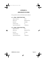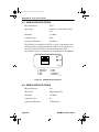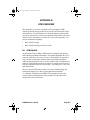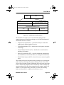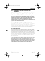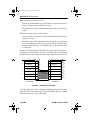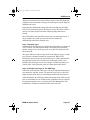
1
book Page 1 Thursday, April 18, 1996 2:18 PM BRIM-A6 USER’S GUIDE book Page i Thursday, April 18, 1996 2:18 PM NOTICE Cabletron Systems reserves the right to make changes in specifications and other information contained in this document without prior notice. The reader should in all cases consult Cabletron Systems to determine whether any such changes have been made. The hardware, firmware, or software described in this manual is subject to change without notice. IN NO EVENT SHALL CABLETRON SYSTEMS BE LIABLE FOR ANY INCIDENTAL, INDIRECT, SPECIAL, OR CONSEQUENTIAL DAMAGES WHATSOEVER (INCLUDING BUT NOT LIMITED TO LOST PROFITS) ARISING OUT OF OR RELATED TO THIS MANUAL OR THE INFORMATION CONTAINED IN IT, EVEN IF CABLETRON SYSTEMS HAS BEEN ADVISED OF, KNOWN, OR SHOULD HAVE KNOWN, THE POSSIBILITY OF SUCH DAMAGES. Copyright 1996 by Cabletron Systems, Inc., P.O. Box 5005, Rochester, NH 03866-5005 All Rights Reserved Printed in the United States of America Order Number: 9031311-01 January 1996 SPECTRUM, LANVIEW, MicroMMAC, and BRIM are registered trademarks and Element Manager, EMM-E6, EMME, EPIM, EPIM-A, EPIM-F1, EPIM-F2, EPIM-F3, EPIM-T, EPIM-X, ESXMIM, FOT-F, FOT-F3, HubSTACK, NBR-420/620, SEH, SEHI, and TMS-3 are trademarks of Cabletron Systems, Inc. All other product names mentioned in this manual may be trademarks or registered trademarks of their respective companies. Printed on BRIM-A6 User’s Guide Recycled Paper i book Page ii Thursday, April 18, 1996 2:18 PM Notice FCC NOTICE This device complies with Part 15 of the FCC rules. Operation is subject to the following two conditions: (1) this device may not cause harmful interference, and (2) this device must accept any interference received, including interference that may cause undesired operation. NOTE: This equipment has been tested and found to comply with the limits for a Class A digital device, pursuant to Part 15 of the FCC rules. These limits are designed to provide reasonable protection against harmful interference when the equipment is operated in a commercial environment. This equipment uses, generates, and can radiate radio frequency energy and if not installed in accordance with the operator’s manual, may cause harmful interference to radio communications. Operation of this equipment in a residential area is likely to cause interference in which case the user will be required to correct the interference at his own expense. WARNING: Changes or modifications made to this device which are not expressly approved by the party responsible for compliance could void the user’s authority to operate the equipment. DOC NOTICE This digital apparatus does not exceed the Class A limits for radio noise emissions from digital apparatus set out in the Radio Interference Regulations of the Canadian Department of Communications. Le présent appareil numérique n’émet pas de bruits radioélectriques dépassant les limites applicables aux appareils numériques de la class A prescrites dans le Règlement sur le brouillage radioélectrique édicté par le ministère des Communications du Canada. VCCI NOTICE This equipment is in the 1st Class Category (information equipment to be used in commercial and/or industrial areas) and conforms to the standards set by the Voluntary Control Council for Interference by Information Technology Equipment (VCCI) aimed at preventing radio interference in commercial and/or industrial areas. Consequently, when used in a residential area or in an adjacent area thereto, radio interference may be caused to radios and TV receivers, etc. Read the instructions for correct handling. ii BRIM-A6 User’s Guide book Page iii Thursday, April 18, 1996 2:18 PM Notice CABLETRON SYSTEMS, INC. PROGRAM LICENSE AGREEMENT IMPORTANT: Before utilizing this product, carefully read this License Agreement. This document is an agreement between you, the end user, and Cabletron Systems, Inc. (“Cabletron”) that sets forth your rights and obligations with respect to the Cabletron software program (the “Program”) contained in this package. The Program may be contained in firmware, chips or other media. BY UTILIZING THE ENCLOSED PRODUCT, YOU ARE AGREEING TO BECOME BOUND BY THE TERMS OF THIS AGREEMENT, WHICH INCLUDES THE LICENSE AND THE LIMITATION OF WARRANTY AND DISCLAIMER OF LIABILITY. IF YOU DO NOT AGREE TO THE TERMS OF THIS AGREEMENT, PROMPTLY RETURN THE UNUSED PRODUCT TO THE PLACE OF PURCHASE FOR A FULL REFUND. CABLETRON SOFTWARE PROGRAM LICENSE 1. LICENSE. You have the right to use only the one (1) copy of the Program provided in this package subject to the terms and conditions of this License Agreement. You may not copy, reproduce or transmit any part of the Program except as permitted by the Copyright Act of the United States or as authorized in writing by Cabletron. 2. OTHER RESTRICTIONS. You may not reverse engineer, decompile, or disassemble the Program. 3. APPLICABLE LAW. This License Agreement shall be interpreted and governed under the laws and in the state and federal courts of New Hampshire. You accept the personal jurisdiction and venue of the New Hampshire courts. EXCLUSION OF WARRANTY AND DISCLAIMER OF LIABILITY 1. EXCLUSION OF WARRANTY. Except as may be specifically provided by Cabletron in writing, Cabletron makes no warranty, expressed or implied, concerning the Program (including its documentation and media). CABLETRON DISCLAIMS ALL WARRANTIES, OTHER THAN THOSE SUPPLIED TO YOU BY CABLETRON IN WRITING, EITHER EXPRESSED OR IMPLIED, INCLUDING BUT NOT LIMITED TO IMPLIED WARRANTIES OF MERCHANTABILITY AND FITNESS FOR A PARTICULAR PURPOSE, WITH RESPECT TO THE PROGRAM, THE ACCOMPANYING WRITTEN MATERIALS, AND ANY ACCOMPANYING HARDWARE. 2. NO LIABILITY FOR CONSEQUENTIAL DAMAGES. IN NO EVENT SHALL CABLETRON OR ITS SUPPLIERS BE LIABLE FOR ANY DAMAGES WHATSOEVER (INCLUDING, WITHOUT LIMITATION, DAMAGES FOR LOSS OF BUSINESS, PROFITS, BUSINESS INTERRUPTION, LOSS OF BUSINESS INFORMATION, SPECIAL, INCIDENTAL, CONSEQUENTIAL, OR RELIANCE DAMAGES, OR OTHER LOSS) ARISING OUT OF THE USE OR INABILITY TO USE THIS CABLETRON PRODUCT, EVEN IF CABLETRON HAS BEEN ADVISED OF THE POSSIBILITY OF SUCH DAMAGES. BECAUSE SOME STATES DO NOT ALLOW THE EXCLUSION OR LIMITATION OF LIABILITY FOR CONSEQUENTIAL OR INCIDENTAL DAMAGES, OR ON THE DURATION OR LIMITATION OF IMPLIED WARRANTIES, IN SOME INSTANCES THE ABOVE LIMITATIONS AND EXCLUSIONS MAY NOT APPLY TO YOU. BRIM-A6 User’s Guide iii book Page iv Thursday, April 18, 1996 2:18 PM Notice UNITED STATES GOVERNMENT RESTRICTED RIGHTS The enclosed product (a) was developed solely at private expense; (b) contains “restricted computer software” submitted with restricted rights in accordance with Section 52227-19 (a) through (d) of the Commercial Computer Software - Restricted Rights Clause and its successors, and (c) in all respects is proprietary data belonging to Cabletron and/or its suppliers. For Department of Defense units, the product is licensed with “Restricted Rights” as defined in the DoD Supplement to the Federal Acquisition Regulations, Section 52.227-7013 (c) (1) (ii) and its successors, and use, duplication, disclosure by the Government is subject to restrictions as set forth in subparagraph (c) (1) (ii) of the Rights in Technical Data and Computer Software clause at 252.227-7013. Cabletron Systems, Inc., 35 Industrial Way, Rochester, New Hampshire 03867-0505. iv BRIM-A6 User’s Guide book Page v Thursday, April 18, 1996 2:18 PM Notice DECLARATION OF CONFORMITY Application of Council Directive(s): 89/336/EEC 73/23/EEC Manufacturer’s Name: Cabletron Systems, Inc. Manufacturer’s Address: 35 Industrial Way PO Box 5005 Rochester, NH 03867 European Representative Name: Mr. J. Solari European Representative Address: Cabletron Systems Limited Nexus House, Newbury Business Park London Road, Newbury Berkshire RG13 2PZ, England Conformance to Directive(s)/Product Standards: EC Directive 89/336/EEC EC Directive 73/23/EEC EN55022 EN 50082-1 EN 60950 Equipment Type/Environment: Networking Equipment, for use in a Commercial or Light Industrial Environment. We the undersigned, hereby declare that the equipment packaged with this notice conforms to the above directives. Manufacturer Legal Representative in Europe Mr. Richard Michaud ___________________________________ Full Name Mr. J. Solari ___________________________________ Full Name Manager of Engineering Services ___________________________________ Title Managing Director - E.M.E.A. ___________________________________ Title Rochester, NH, USA ___________________________________ Location Newbury, Berkshire, England ___________________________________ Location BRIM-A6 User’s Guide v book Page vii Thursday, April 18, 1996 2:18 PM CONTENTS CHAPTER 1 INTRODUCTION 1.1 Using This Manual....................................................................... 1-1 1.2 Document Conventions ............................................................... 1-2 1.3 BRIM-A6 Overview ...................................................................... 1-3 1.4 BRIM-A6 Features....................................................................... 1-3 1.5 BRIM-A6 Specifications............................................................... 1-4 1.6 Related Manuals.......................................................................... 1-4 1.7 Getting Help................................................................................. 1-5 CHAPTER 2 INSTALLATION 2.1 Unpacking the BRIM.................................................................... 2-1 2.2 Installing APIMs........................................................................... 2-2 2.3 Installing BRIMs........................................................................... 2-3 2.3.1 Installing a BRIM in a MIM .............................................. 2-3 2.3.2 Installing a BRIM in a Hub .............................................. 2-5 CHAPTER 3 LOCAL MANAGEMENT 3.1 Local Management Keyboard Conventions................................. 3-2 3.2 Using LIM to create PVCs ........................................................... 3-3 3.2.1 ATM Connection Tables Screen Fields .......................... 3-4 3.2.2 ATM Connection Tables Screen Commands ................. 3-5 3.2.3 Using ATM Connection Tables Screen Commands ....... 3-5 3.2.4 Adding PVCs to the Connection Tables Screen ............. 3-6 3.2.5 Deleting PVCs from the Connection Tables Screen ....... 3-6 3.3 Using LM to Create PVCs ........................................................... 3-7 3.3.1 BRIM-A6 Setup Screen Fields ........................................ 3-8 3.3.2 BRIM-A6 Setup Screen Commands ............................... 3-9 3.3.3 Using BRIM-A6 Setup Screen Commands ................... 3-10 3.3.4 Accessing the BRIM-A6 Add/Delete Entry Screen ....... 3-10 3.3.5 BRIM-A6 Add/Delete Entry Screen Fields .................... 3-11 3.3.6 BRIM-A6 Add/Delete Entry Screen Commands ........... 3-12 3.3.7 Adding a PVC ............................................................... 3-12 3.3.8 Modifying a PVC ........................................................... 3-13 3.3.9 Deleting a PVC ............................................................. 3-14 CHAPTER 4 LANVIEW LEDs 4.1 BRIM-A6 LEDs ............................................................................ 4-1 4.2 APIM LEDs .................................................................................. 4-2 BRIM-A6 User’s Guide vii book Page viii Thursday, April 18, 1996 2:18 PM Contents APPENDIX A APIM SPECIFICATIONS A.1 APIM-11 Specifications ............................................................... A-1 A.2 APIM-21 Specifications ............................................................... A-1 A.3 APIM-22 Specifications ............................................................... A-2 A.4 APIM-29 Specifications ............................................................... A-2 A.5 APIM-67 Specifications ............................................................... A-3 APPENDIX B ATM OVERVIEW B.1 ATM Basics ................................................................................. B-1 B.2 The ATM Cell .............................................................................. B-2 B.3 The ATM Network ....................................................................... B-4 B.3.1 Virtual Channels and Virtual Paths ................................. B-4 B.3.2 Permanent and Switched Virtual Channels .................... B-5 B.4 ATM Protocol .............................................................................. B-5 viii BRIM-A6 User’s Guide book Page 1 Thursday, April 18, 1996 2:18 PM CHAPTER 1 INTRODUCTION Welcome to the Cabletron Systems BRIM-A6 User’s Guide. This manual provides the following information: • Describes BRIM-A6 features • Explains how to install the BRIM-A6 in a Cabletron Systems Media Interface Module (MIM) or standalone hub • Outlines specifications for the Cabletron Systems Asynchronous Transfer Mode (ATM) Bridge/Router Interface Module (BRIM) The BRIM-A6 provides additional connectivity/functionality to various Cabletron Systems MIMs and standalone hubs. You should have a general working knowledge of ATM networks and the ATM User-Network Interface Specification, as proposed in the ATM Forum, prior to installing the BRIM-A6. If you need a basic overview of ATM, refer to Appendix B, ATM Overview. 1.1 USING THIS MANUAL Read through this manual completely to familiarize yourself with its content and to gain an understanding of the features and capabilities of the BRIM-A6. The following list provides an overview of each section of this manual: Chapter 1, Introduction, outlines the contents of this manual, describes BRIM-A6 features and concludes with a list of related manuals. Chapter 2, Installation, describes how to install ATM Port Interface Modules (APIMs) into the BRIM-A6. This chapter also explains how to install a BRIM-A6 into a MIM or a standalone hub. Chapter 3, Local Management, describes how to create Permanent Virtual Connection using Cabletron Systems Local Interface Management (LIM) or Cabletron Systems Local Management (LM). Chapter 4, LANVIEW LEDS, describes how to use the BRIM-A6 LEDs to monitor BRIM performance and status. BRIM-A6 User’s Guide Page 1-1 book Page 2 Thursday, April 18, 1996 2:18 PM Chapter 1: Introduction Appendix A, APIM Specifications, describes specifications and features for each of the APIMs available for the BRIM-A6. Appendix B, ATM Overview, provides a basic overview of ATM technology. 1.2 DOCUMENT CONVENTIONS The following conventions are used throughout this document: NOTE Note symbol. Calls the reader’s attention to any item of information that may be of special importance. Tip symbol. Conveys helpful hints concerning procedures or actions. TIP ! Caution symbol. Contains information essential to avoid damage to the equipment. CAUT ION Warning symbol. Warns against an action that could result in equipment damage, personal injury or death. Page 1-2 BRIM-A6 User’s Guide book Page 3 Thursday, April 18, 1996 2:18 PM BRIM-A6 Overview 1.3 BRIM-A6 OVERVIEW The BRIM-A6 extends the functionality of your MIM or standalone hub to include remote bridging/routing capability. It allows remote connectivity using ATM technology. The BRIM-A6 is equipped with one slot that supports a Cabletron Systems APIM for ATM connectivity. Cabletron Systems provides a variety of APIMs that let you select the configuration of your choice. The BRIM-A6 supports two types of Virtual Channels: Permanent Virtual Channels (PVCs), and Switched Virtual Channels (SVCs). It also supports the ATM Forum’s User-Network-Interface (UNI) for SVC signaling, and FORE Systems’ Simple Protocol for ATM Network Signaling (SPANS). Because of this support, the BRIM-A6 is not only standards based, but takes advantage of FORE’s ATM signaling enhancements while providing guaranteed interoperability with existing FORE ATM networks. 1.4 BRIM-A6 FEATURES ATM Port Interface Modules (APIMs) The BRIM-A6 uses Cabletron Systems APIMs for ATM connectivity. You can easily install APIMs into the BRIM for the interface of your choice. APIMs support multiple types of physical layer cable types and are fully compliant with the ATM Forum’s “UTOPIA” specification. MIB Support For additional information on how to extract and compile individual MIBs, refer to the Release Notes, or contact Cabletron Systems Technical Support (see Section 1.7, Getting Help). LANVIEW Diagnostic LEDs Cabletron Systems provides a visual diagnostic and monitoring system called LANVIEW with the BRIM-A6. LANVIEW LEDs help you quickly identify bridge and link status. BRIM-A6 User’s Guide Page 1-3 book Page 4 Thursday, April 18, 1996 2:18 PM Chapter 1: Introduction 1.5 BRIM-A6 SPECIFICATIONS This section describes environment specifications and safety requirements for the BRIM-A6. Cabletron Systems reserves the right to change these specifications at any time without notice. Environment Operating Temperature: 5°C to 40°C (41°F to 104°F) Storage Temperature: -30°C to 90°C (-22°F to 194°F) Operating Humidity: 5% to 95% (non-condensing) Safety This unit meets the safety requirements of UL1950, CSA C22.2 No. 950, and EN60950. EMI This unit meets the EMI requirements of FCC Part 15 Class A, EN55022 Class A and VCCI Class I. EMC This unit meets the EMC requirements of EN 50082-1 including: IEC 801-2 (ESD), IEC 801-3 (Radiated Susceptibility), and IEC 801-4 (EFT/B). 1.6 RELATED MANUALS Use the following manuals to supplement the procedures and other technical data provided in this manual. This manual references procedures in these manuals, where appropriate, but does not repeat them. Cabletron Systems EMM-E6 User’s Guide Cabletron Systems ESXMIM Installation Guide Cabletron Systems MicroMMAC User’s Guide Cabletron Systems NBR-620/420/220 Installation Guide and NBR-620/420/220 Local Management Guide Page 1-4 BRIM-A6 User’s Guide book Page 5 Thursday, April 18, 1996 2:18 PM Getting Help 1.7 GETTING HELP If you need additional support related to the BRIM-A6, or if you have any questions, comments, or suggestions concerning this manual, contact Cabletron Systems Technical Support: By phone By CompuServe By Internet mail By FTP Login Password BRIM-A6 User’s Guide (603) 332-9400 Monday-Friday; 8 A.M. – 8 P.M. Eastern Time GO CTRON from any ! prompt [email protected] ctron.com (134.141.197.25) anonymous your email address Page 1-5 book Page 1 Thursday, April 18, 1996 2:18 PM CHAPTER 2 INSTALLATION This chapter contains instructions for unpacking the BRIM, installing APIMs, and installing the BRIM into Cabletron Systems devices that support BRIM technology. To install the BRIM and APIMs, you need the following tools: • 1 disposable grounding wrist strap (provided with any MIM or hub) • 1 Phillips-head screwdriver. ! CAUT ION The BRIM-A6 and the host MIM or hub are sensitive to static discharges. Use a grounding strap and observe all static precautions during this procedure. Failure to do so could result in damage to the BRIM-A6 or the host MIM or hub. 2.1 UNPACKING THE BRIM Unpack the BRIM as follows: 1. Remove the shipping box material covering the BRIM. 2. Carefully remove the module from the shipping box. Leave the module in its non-conductive bag until you are ready to install. 3. Attach the disposable grounding strap to your wrist (refer to the instructions on the disposable grounding strap package). 4. After removing the module from its non-conductive bag, visually inspect the device. If you notice any signs of damage, contact Cabletron Systems Technical Support immediately. BRIM-A6 User’s Guide Page 2-1 book Page 2 Thursday, April 18, 1996 2:18 PM Chapter 2: Installation 2.2 INSTALLING APIMS To install an APIM into the BRIM-A6: 1. Attach the disposable grounding strap to your wrist (refer to the instructions on the disposable grounding strap package). 2. Remove the two faceplate screws from the BRIM. See Figure 2-1. 3. Remove the three screws from the BRIM standoffs. See Figure 2-1. 4. Insert the APIM connector into the BRIM connector. See Figure 2-1. APIM SCREWS APIM CONNECTOR STS LNK APIM STANDOFF BRIM CONNECTOR BRIM -A6 STS XMT PW R RCV FACEPLATE SCREWS 131101 Figure 2-1 Installing an APIM 5. Press down firmly on the APIM until the APIM connector slides all the way into the BRIM connector. Ensure the APIM sits flush on the standoffs. 6. Secure the APIM with the screws provided with the APIM. 7. Reattach the faceplate to the BRIM. Page 2-2 BRIM-A6 User’s Guide book Page 3 Thursday, April 18, 1996 2:18 PM Installing BRIMs 2.3 INSTALLING BRIMS Only qualified personnel should install the BRIM. ! CAUT ION You can install a BRIM in any Cabletron Systems device that supports BRIM technology (e.g., EMM-E6, MicroMMAC). Refer to the release notes for the version of firmware running on the Cabletron Systems device to ensure that the BRIM-A6 is supported. The following subsections provide generic instructions for installing a BRIM-A6 in a MIM or in a standalone hub. Refer to your specific MIM or standalone hub documentation for exact BRIM slot and connector locations. 2.3.1 Installing a BRIM in a MIM To install a BRIM-A6 in a MIM that supports BRIM technology: 1. Power-down the MMAC hub and remove all power cords. NOTE Cabletron Systems recommends that you power-down the hub even though Cabletron MIMs have “hot swap” capabilities. 2. Disconnect all cables from the MIM. Note the ports to which these cables attach. 3. Attach the disposable grounding strap to your wrist (refer to the instructions outlined on the disposable grounding strap package). 4. Unscrew the top and bottom knurled knobs of the MIM face plate. 5. Slide out the MIM, and place it on its side with the internal components facing up. 6. Remove the mounting screws and the BRIM coverplate. See Figure 2-2. 7. Remove the standoff screws. See Figure 2-2. BRIM-A6 User’s Guide Page 2-3 book Page 4 Thursday, April 18, 1996 2:18 PM Chapter 2: Installation STANDOFF SCREW STANDOFF BRIM COVERPLATE FACEPLATE MOUNTING SCREW 142902 Figure 2-2 Removing the BRIM Coverplate STANDOFF SCREW S ST K LN IM AP 6 -A R IMSTS PW BR V T RC XM STANDOFF BRIM CONNECTOR FACEPLATE MOUNTING SCREW 131102 Figure 2-3 Page 2-4 Installing the BRIM BRIM-A6 User’s Guide book Page 5 Thursday, April 18, 1996 2:18 PM Installing BRIMs 8. Place the BRIM behind the MIM faceplate. See Figure 2-3. 9. Insert the connector pins of the BRIM-A6 into the BRIM connector on the MIM. 10. Press down firmly on the back of the BRIM until the pins slide all the way into the connector holes. NOTE Ensure that the standoffs on the MIM align with the standoff screw holes on the BRIM. 11. Reinstall the mounting screws and the standoff screws. 12. Reinstall the MIM in the MMAC. 13. Reattach all MMAC power cords. 14. Reattach the network cabling to the MIM. 15. Refer to Chapter 3 for instructions on configuring the BRIM-A6 using Local Management. 2.3.2 Installing a BRIM in a Hub To install a BRIM-A6 into a standalone hub that supports BRIM technology: 1. Power down the hub and remove the power cord. 2. Disconnect all cables from the hub. Note the ports to which these cables attach. Ensure that you remove the power cord and ONLY the screws required to remove the chassis cover. Failure to comply could result in an electric shock hazard. 3. Attach the disposable grounding strap to your wrist (refer to the instructions outlined on the disposable grounding strap package). 4. Remove the hub chassis cover (refer to your specific hub documentation for instructions on removing the hub chassis cover). BRIM-A6 User’s Guide Page 2-5 book Page 6 Thursday, April 18, 1996 2:18 PM Chapter 2: Installation 5. Remove the faceplate mounting screws and the BRIM coverplate. See Figure 2-2. 6. Remove the standoff screws. See Figure 2-2. 7. Place the BRIM behind the hub faceplate. See Figure 2-3. 8. Insert the connector pins of the BRIM-A6 into the BRIM connector on the hub. 9. Press down firmly on the back of the BRIM-A6 until the pins slide all the way into the connector holes. NOTE Ensure that the standoffs on the hub align with the standoff screw holes on the BRIM. 10. Reinstall the faceplate mounting screws and the standoff screws. Ensure that the chassis cover is in place before reconnecting the power cord. 11. Reattach the chassis cover to the hub, reconnect the power cord, and reconnect the hub to your network. 12. Refer to Chapter 3 for instructions on configuring the BRIM-A6 using Local Management. Page 2-6 BRIM-A6 User’s Guide book Page 1 Thursday, April 18, 1996 2:18 PM CHAPTER 3 LOCAL MANAGEMENT This chapter explains how to configure Permanent Virtual Connections (PVCs) using one of the following local management applications: • Cabletron Systems Local Interface Management (LIM) • Cabletron Systems Local Management (LM) NOTES The method used to configure PVCs depends on the firmware image of the host MIM or standalone hub. Refer to the section that applies to the local management application on your host MIM or standalone hub. To set up and access a local management application, refer to the host MIM or standalone hub user’s guide for instructions. Complete the following instructions before configuring the BRIM-A6 using a local management application. • An APIM must be installed in the BRIM-A6. • The BRIM-A6 must be installed in the host MIM or standalone hub. • The device must be up and running. • A management terminal must be configured and properly connected to the host MIM or standalone hub in which the BRIM-A6 resides. NOTE Refer to Appendix B, ATM Overview for additional information concerning PVCs and ATM technology. BRIM-A6 User’s Guide Page 3-1 book Page 2 Thursday, April 18, 1996 2:18 PM Chapter 3: Local Management 3.1 LOCAL MANAGEMENT KEYBOARD CONVENTIONS All key names appear in this manual as capital letters. For example, the Enter key appears as ENTER and the Backspace Key appears as BACKSPACE. Table 3-1 explains the keyboard conventions used in this manual as well as the key functions. Table 3-1 Keyboard Conventions Key Function ENTER Key and RETURN Key These are selection keys that perform the same LIM or LM function. For example, “Press ENTER” means that you can press either ENTER or RETURN, unless this manual specifically instructs you otherwise. SPACE bar and BACKSPACE Key These keys cycle through selections in some LIM and LM fields. Use the SPACE bar to cycle forward through selections and use BACKSPACE to cycle backward through selections. Arrow Keys These are navigation keys. Use the UP-ARROW, DOWN-ARRROW, LEFT-ARROW, and RIGHT-ARROW keys to move the screen cursor. For example, “Use the arrow keys” means to press whichever arrow key moves the cursor to the desired field on the screen. Page 3-2 BRIM-A6 User’s Guide book Page 3 Thursday, April 18, 1996 2:18 PM Using LIM to create PVCs 3.2 USING LIM TO CREATE PVCs LIM consists of the ATM Connection Tables screen. This screen displays both Permanent Virtual Connections (PVCs) and Switched Virtual Connections (SVCs). SVCs are dynamic connections that are created and deleted as required by applications, equipment, and ATM facilities. SVCs can not be deleted from the ATM Connection Tables screen. To access the ATM Connection Tables screen, perform the following steps: 1. Use the arrow keys to select BRIM 1 Extended Features from the Feature Selection screen. 2. Press ENTER. The ATM Connection Tables screen, Figure 3-1 appears. ATM Connection Tables Total Channels: 4 Edit Static Entry: VPI: Index 1 2 3 4 VCI 14 15 4 10 VCI: Mode: ADD Connection Table SAVE VPI 0 0 2 3 CLEAR VCCS Type NEXT PREVIOUS MAC ADDRESS RETURN 131104 Figure 3-1 BRIM-A6 User’s Guide The ATM Connection Tables Screen Page 3-3 book Page 4 Thursday, April 18, 1996 2:18 PM Chapter 3: Local Management 3.2.1 ATM Connection Tables Screen Fields The following list explains each of the ATM Connection Tables screen fields. Total Channels This field displays the number of active PVCs and SVCs connected to the BRIM-A6. Edit Static Entry The Edit Static Entry section consists of the Virtual Path Identifier (VPI), Virtual Channel Identifier (VCI), and Mode fields. These fields let you add or delete VPIs and VCIs from the Connection Table. The following list describes each of the Edit Static Entry Fields: • VPI: This field lets you add (or delete) VPIs to the Connection Table. You can assign numbers 0-3 for VPIs. • VCI: This field lets you add (or delete) VCIs to the Connection Table. You can assign numbers 0-1023 for VCIs. • Mode: This field lets you select the edit mode. Select ADD to create PVCs on the Connection Table or DELETE to remove PVCs from the Connection Table. Connection Table The Connection Table displays the status of each PVC and SVC. The following list describes each of the Connection Table fields: • Index: Displays the channel number of each PVC and SVC. • VPI: Displays the VPI number of each PVC and SVC. • VCI: Displays the VCI number of each PVC and SVC. • Type: This field will be supported when the ATM Forum LAN Emulation is available. • MAC ADDRESS: This field will be supported when the ATM Forum LAN Emulation is available. Page 3-4 BRIM-A6 User’s Guide book Page 5 Thursday, April 18, 1996 2:18 PM Using LIM to create PVCs 3.2.2 ATM Connection Tables Screen Commands The following commands appear at the bottom of the ATM Connection Tables screen commands: Save This command lets you save all changes to the Connection Tables screen. Clear VCCs The Clear Virtual Channel Connection (VCC) command lets you clear all PVCs from the Connection Tables screen. This command does not let you clear SVCs from the Connection Tables screen because SVCs are dynamic connections that are created and deleted as required by applications, equipment, and ATM facilities. NOTE Connection 1 (VPI-0, VCI-14) and Connection 2 (VPI-0, VCI-15) are used by Fore Systems SPAN signalling and can not be deleted from the Connection Tables screen. Next/Previous This command lets you scroll to the next screen or back to the previous screen. If the ATM Connection Tables screen has over 6 channels, it automatically continues onto a new screen. Return This command lets you exit from the ATM Connections Tables screen. 3.2.3 Using ATM Connection Tables Screen Commands To use ATM Connection Tables screen commands, perform the following steps: 1. Use the arrow keys to highlight an ATM Connection Table screen command. 2. Press ENTER, LIM executes the selected command. BRIM-A6 User’s Guide Page 3-5 book Page 6 Thursday, April 18, 1996 2:18 PM Chapter 3: Local Management 3.2.4 Adding PVCs to the Connection Tables Screen To add PVCs to the Connection Tables screen, perform the following steps: 1. Use the arrow keys to highlight the Mode field. 2. Press ENTER to select ADD. 3. Use the arrow keys to highlight the VPI field. 4. Enter the VPI number you want to add and press ENTER. 5. Use the arrow keys to highlight the VCI field. 6. Enter the VCI number you want to add and press ENTER. 7. Use the arrow keys to highlight the SAVE command at the bottom of the screen. 8. Press ENTER. The “ADDING CHANNELS” message appears indicating that LIM has saved all changes to memory. 3.2.5 Deleting PVCs from the Connection Tables Screen To delete PVCs from the Connection Tables screen, perform the following steps: 1. Use the arrow keys to highlight the Mode field. 2. Press ENTER to select DELETE. 3. Use the arrow keys to highlight the PVC you want to delete. 4. Use the arrow keys to highlight the SAVE command at the bottom of the screen. 5. Press ENTER. The “DELETING CHANNELS” message appears indicating that LIM has saved all changes to memory. Page 3-6 BRIM-A6 User’s Guide book Page 7 Thursday, April 18, 1996 2:18 PM Using LM to Create PVCs 3.3 USING LM TO CREATE PVCS LM for the BRIM-A6 provides screens that let you add, delete or modify PVCs. This screen displays both Permanent Virtual Connections (PVCs) and Switched Virtual Connections (SVCs). SVCs are dynamic connections that are created and deleted as required by applications, equipment, and ATM facilities. SVCs can not be deleted from the LM screens. LM consists of the following screens: • The BRIM-A6 Setup screen: This is a view only screen which displays the settings for each PVC and SVC. • The BRIM-A6 Add/Delete Entry screen: This screen allows you to add, delete, and configure PVCs. To access BRIM-A6 LM, perform the following steps: 1. Use the arrow keys to select the BRIM-A6 option from the Setup Menu screen. 2. Press ENTER. The BRIM-A6 Setup screen, Figure 3-2, appears. Local Management Flash Image Version: XX.XX.XX BRIM-A6 SETUP ATM Port Total Current Connections: 2 VPI VCI Encapsulation Type AAL Type Oper. Status 0 0014 VC Mux Bridged 802.3 5 Enabled 0 0040 LLC Encapsulation 3/4 Disabled PREVIOUS NEXT ADD/DELETE ENTRY RETURN 131105 Figure 3-2 BRIM-A6 User’s Guide The BRIM-A6 Setup Screen Page 3-7 book Page 8 Thursday, April 18, 1996 2:18 PM Chapter 3: Local Management 3.3.1 BRIM-A6 Setup Screen Fields The BRIM-A6 Setup screen displays settings for each PVC and SVC that is configured to the BRIM. The following list explains each of the BRIM-A6 Setup screen fields: ATM Port Total Current Connections: X This field displays how many connections (PVCs and SVCs) are configured to the BRIM-A6. VPI This field displays the Virtual Path Identifier (VPI) of each connection. You assign VPIs in the BRIM-A6 Add/Delete Entry screen. VCI This field displays the Virtual Channel Identifier (VCI) of each connection. You assign VCIs in the BRIM-A6 Add/Delete Entry screen. Encapsulation Type This field displays the method used to encapsulate data at the ATM Adaptation Layer 5 (AA-L5) for each connection. The BRIM-A6 supports the following methods of encapsulation: • VC Mux 802.3 LANE: VC Based Multiplexed 802.3 LAN Emulation This method is specified by the ATM Forum LAN Emulation specification. This is the default encapsulation method. • VC Mux Bridged 802.3: VC Based Multiplexing for bridged protocols as defined by the IETF RFC 1483. • LLC Encapsulation: Logical Link Control for Bridged Protocols as defined by the IETF RFC 1483. AAL Type This field displays the ATM Adaptation Layer (AAL) type of each connection. The AAL divides the user information into segments suitable for packaging into series of ATM cells. The ATM Forum’s LAN Emulation specification dictates that AAL-5 be used for all LAN emulation traffic. The BRIM-A6 supports AAL-5 and AAL-3/4. Oper. Status This field displays the operational status of each connection. Possible conditions are Enabled or Disabled. Page 3-8 BRIM-A6 User’s Guide book Page 9 Thursday, April 18, 1996 2:18 PM Using LM to Create PVCs 3.3.2 BRIM-A6 Setup Screen Commands Commands appear at the bottom of the BRIM-A6 Setup screen. The following list explains each of the BRIM-A6 Setup screen commands: Previous This command lets you scroll to the previous screen (if the BRIM-A6 Setup screen has over five connections, it automatically continues onto a new screen). Next This command lets you scroll to the next screen (if the BRIM-A6 Setup screen has over five connections, it automatically continues onto a new screen). Add/Delete Entry This command lets you access the BRIM-A6 Add/Delete Entry screen. Return This command lets you exit the BRIM-A6 Setup screen. BRIM-A6 User’s Guide Page 3-9 book Page 10 Thursday, April 18, 1996 2:18 PM Chapter 3: Local Management 3.3.3 Using BRIM-A6 Setup Screen Commands To select BRIM-A6 Setup screen commands, perform the following steps: 1. Use the arrow keys to highlight a BRIM-A6 Setup screen command. 2. Press ENTER, LM executes the selected command. 3.3.4 Accessing the BRIM-A6 Add/Delete Entry Screen To access the BRIM-A6 Add/Delete Entry screen from the BRIM-A6 Setup screen, perform the following steps: 1. Use the arrow keys to highlight the Add/Delete Entry selection at the bottom of the BRIM-A6 Setup screen. 2. Press ENTER, the BRIM-A6 Add/Delete Entry screen Figure 3-3 appears. Local Management Flash Image Version: XX.XX.XX BRIM-A6 ADD/DELETE ENTRY VPI VCI AAL Type Encapsulation Type 0 0004 [5] [VC Mux Bridged 802.3 ] ADD/MODIFY (DELETE) RETURN 131106 Figure 3-3 Page 3-10 The BRIM-A6 Add/Delete Entry Screen BRIM-A6 User’s Guide book Page 11 Thursday, April 18, 1996 2:18 PM Using LM to Create PVCs 3.3.5 BRIM-A6 Add/Delete Entry Screen Fields The BRIM-A6 Add/Delete Entry screen lets you add, delete, or modify PVCs. This screen does not let you clear SVCs from the Connection Table screen. NOTE Connection 1 (VPI-0, VCI-14) and Connection 2 (VPI-0, VCI-15) are used by Fore Systems SPAN signalling and can not be deleted from the Connection Table screen. The following list explains each of the BRIM-A6 Add/Delete Entry screen fields: VPI Use this field to enter the VPI of the PVC you want to add, delete or modify. This field allows values of 0-3. VCI Use this field to enter the VCI of the PVC you want to add, delete, or modify. This field allows values of 0-1023. AAL Type Use this field to select the ATM Adaptation Layer for the PVC you want to add, delete, or modify. Press the SPACE bar to toggle selections 5 (AAL-5) and 3/4 (AAL-3/4). The default selection is 5. Encapsulation Type Use this field to select the data encapsulation type used over AAL-5. Press the SPACE bar to select VC Mux Bridged 802.3 or LLC Encapsulation. The default selection is VC Mux Bridged 802.3. BRIM-A6 User’s Guide Page 3-11 book Page 12 Thursday, April 18, 1996 2:18 PM Chapter 3: Local Management 3.3.6 BRIM-A6 Add/Delete Entry Screen Commands The following commands appear at the bottom of the BRIM-A6 Add/Delete Entry screen: Add/Modify This command lets you add or modify PVCs to the BRIM-A6 Add/Delete Entry screen. Delete This command lets you delete PVCs from the BRIM-A6 Add/Delete Entry screen. This command appears only after you add or modify an existing PVC. Return This command lets you exit from the BRIM-A6 Add/Delete Entry screen. 3.3.7 Adding a PVC To add a PVC, perform the following steps: 1. Use the arrow keys to highlight the VPI field and enter a VPI value from 0-3. LM automatically saves entries when you exit the field. NOTE 2. Use the arrow keys to highlight the VCI field and enter a VCI value from 0-1023. 3. Use the arrow keys to highlight the AAL Type field and press the SPACE bar until the desired AAL Type appears. 4. Use the arrow keys to highlight the Encapsulation Type field and press the SPACE bar until the desired Encapsulation Type appears. 5. Use the arrow keys to highlight the ADD/MODIFY command. 6. Press ENTER. The “ENTRY ADDED” message appears at the top of the screen indicating that LM has added the PVC. Page 3-12 BRIM-A6 User’s Guide book Page 13 Thursday, April 18, 1996 2:18 PM Using LM to Create PVCs 3.3.8 Modifying a PVC To modify an existing PVC, perform the following steps: 1. Use the arrow keys to highlight the VPI field and enter the VPI value you want to change. LM automatically saves entries when you exit the field. NOTE 2. Use the arrow keys to highlight the VCI field and enter the VCI value you want to change. 3. Use the arrow keys to highlight the AAL Type field and press the SPACE bar until the desired AAL Type appears. 4. Use the arrow keys to highlight the Encapsulation Type field and press the SPACE bar until the desired Encapsulation Type appears. 5. Use the arrow keys to select the ADD/MODIFY command. 6. Press ENTER. The “ENTRY DELETED” then “ENTRY ADDED” messages appears at the top of the screen indicating that LM has modified the PVC. BRIM-A6 User’s Guide Page 3-13 book Page 14 Thursday, April 18, 1996 2:18 PM Chapter 3: Local Management 3.3.9 Deleting a PVC To delete a PVC, perform the following steps: 1. Use the arrow keys to highlight the VPI field and enter the VPI of the PVC you want to delete. LM automatically saves entries when you exit the field. NOTE 2. Use the arrow keys to highlight the VCI field and enter the VCI of the PVC you want to delete. 3. Use the arrow keys to highlight the AAL Type field and press the SPACE bar until the AAL Type of the PVC you want to delete appears. 4. Use the arrow keys to highlight the Encapsulation Type field and press the SPACE bar until the Encapsulation Type of the PVC you want to delete appears. 5. Use the arrow keys to highlight the DELETE command. 6. Press ENTER. The “ENTRY DELETED” message appears at the top of the screen indicating that LM has deleted the PVC. Page 3-14 BRIM-A6 User’s Guide book Page 1 Thursday, April 18, 1996 2:18 PM CHAPTER 4 LANVIEW LEDs This chapter describes how to use LANVIEW LEDs to monitor BRIM status and diagnose BRIM problems. Figure 4-1 shows the location of each of the BRIM-A6 LEDs as well as the APIM LEDs. BRIM-A6 STS STS PWR LNK APIM XMT RCV 131103 Figure 4-1 The BRIM-A6 4.1 BRIM-A6 LEDs Table 4-1 describes each of the BRIM-A6 LEDs. Table 4-1 BRIM LEDs LED Definition STS (Status) Green - Board OK. Red - Board Error. Yellow - Standby. PWR (Power) Green (on) - Power is on. Off - No power. XMT (Transmit) Green - Cells being transmitted. RCV (Receive) Yellow - Cells being received. BRIM-A6 User’s Guide Page 4-1 book Page 2 Thursday, April 18, 1996 2:18 PM Chapter 4: LANVIEW LEDs 4.2 APIM LEDs Table 4-2 describes each of the APIM LEDs. Table 4-2 APIM LEDs LED Definition LNK (Link) Green - Have link. Off - No link. STS (Status) Green - APIM OK. Red - Fault with media. In most cases, the APIM automatically corrects this condition without interrupting operations. If the LED is red and remains red, contact Cabletron Systems Technical Support. Page 4-2 BRIM-A6 User’s Guide book Page 1 Thursday, April 18, 1996 2:18 PM APPENDIX A APIM SPECIFICATIONS This Appendix describes the ATM Port Interface Modules. A.1 APIM-11 SPECIFICATIONS Physical Interface: TAXI Media Type: Multimode Fiber Data Rate: 100 Mbps Connector Type: SC Typical Link Distance: 2 Kilometers A.2 APIM-21 SPECIFICATIONS Physical Interface: OC3 Media Type: Multimode Fiber Data Rate: 155 Mbps Connector Type: SC Typical Link Distance: 2 Kilometers BRIM-A6 User’s Guide Page A-1 book Page 2 Thursday, April 18, 1996 2:18 PM Appendix A: APIM Specifications A.3 APIM-22 SPECIFICATIONS Physical Interface: STS3 Media Type: Category V Unshielded Twisted Pair Data Rate: 155 Mbps Connector Type: RJ45 Typical Link Distance: 100 Meters The APIM-22 is considered an ATM User Device and therefore has a different signal pin assignment that the ATM Network Equipment as specified by the ATM Forum User-Network Interface (UNI) specification. Figure A-1 shows the pin assignments for the APIM-22. STS LNK 12345678 APIM-22 1. Transmit + 2. Transmit 3. N/A 4. N/A 5. N/A 6. N/A 7. Receive + 8. Receive 142912 Figure A-1 APIM-22 Pin Assignments A.4 APIM-29 SPECIFICATIONS Physical Interface: OC3 Media Type: Single Mode Fiber Data Rate: 155 Mbps Connector Type: SC Typical Link Distance: 25 Kilometers Page A-2 BRIM-A6 User’s Guide book Page 3 Thursday, April 18, 1996 2:18 PM APIM-67 Specifications A.5 APIM-67 SPECIFICATIONS Physical Interface: DS3 Media Type: 75 Ohm Coaxial Cable Data Rate: 45 Mbps Connector Type: BNC Typical Link Distance: 136 Meters ! CAUT ION The APIM-67 does not use Cell Payload Scrambling. Scrambling must be disabled on any DS3 device connected to the APIM-67. The APIM-67 conforms to the electrical characteristics specified by ANSI T1.404-1989 Carrier-to-Customer Installation-DS3 Metallic Interface Specification, section 5.12 Grounding Arrangements. In accordance with this specification, each channel (Transmit and Receive) must be grounded at one end. Cabletron Systems ships the APIM-67 with the following default jumper settings: • Receive channel jumper - grounded • Transmit channel jumper - not grounded Figure A-2 shows the location and default setting of each jumper. Refer to Figure A-2 if you need to change the jumper settings to properly connect the APIM-67 to another DS3 device. RECEIVE CHANNEL JUMPER (GROUNDED) TRANSMIT CHANNEL JUMPER (NOT GROUNDED) 142910 Figure A-2 BRIM-A6 User’s Guide The APIM-67 Default Jumper Settings Page A-3 book Page 1 Thursday, April 18, 1996 2:18 PM APPENDIX B ATM OVERVIEW This Appendix covers basic Asynchronous Transfer Mode (ATM) network operation and concepts that are critical to ATM network design and installation. The ATM Forum User-Network Interface Specification provides greater detail on ATM access methods and should be referenced whenever more information is needed. The scope of this appendix is to provide information regarding: • Basic ATM Concepts. • Basic ATM technology and how it works. B.1 ATM BASICS Asynchronous Transfer Mode (ATM) defines a method of transmitting and switching broadband information. This method highlights the use of relatively small, fixed-size cells (53 bytes) of information as opposed to large, variable-sized packets found in other networking transmission methods (ranging from 64 bytes to well over 4800 bytes). In addition, this method is being heralded as the first solution in erasing barriers between local-area networks and wide-area networks – providing voice, video, and data transmission. The use of small ATM cells provides cost, speed, manufacturing, and technical advantages over other existing transmission methods (i.e., Ethernet, Token Ring, and FDDI). This appendix touches upon several of these advantages and, when possible, describes them in as much detail as the scope allows. BRIM-A6 User’s Guide Page B-1 book Page 2 Thursday, April 18, 1996 2:18 PM Appendix B: ATM Overview B.2 THE ATM CELL One major difference between ATM and current transmission methods is that instead of using variable-length packets, ATM transmits fixed-size cells. (See Figure B-1.) Header Data 5 Bytes 48 Bytes Figure B-1 ATM Cells ATM uses three types of cells – Assigned, Unassigned, and Idle. Assigned cells carry actual traffic. Unassigned cells are free and waiting to be assigned traffic. Idle cells are used to separate cells, provide receiver synchronization (byte alignment), and reserve bandwidth for another channel (i.e., occupy bandwidth between transmissions). Idle cells do not receive traffic. ATM cells total 53 bytes long and consist of two general parts: the Header field and the Data field. The Header field consists of 5 bytes and contains management/control information for the cell. The Data field contains 48 bytes of information. Figure B-2 shows the additional components of the Header field. Page B-2 BRIM-A6 User’s Guide book Page 3 Thursday, April 18, 1996 2:18 PM The ATM Cell Header Data Generic Flow Control (GFC) Virtual Path Identifier (VPI) VPI VCI/VPI Virtual Channel Identifier (VCI) VCI Payload Type Reserved Header Check Sequence Figure B-2 ATM Header Field Breakdown The Header field is made up of several sub-fields which provide management/control information relating to a cell. Brief descriptions of each header field are as follows: • Generic Flow Control (GFC) – provides the ability to control the traffic flow for different grades of service. • Virtual Path Identifier (VPI) – identifies the virtual path to which the cell belongs. • Virtual Channel Identifier (VCI) – identifies the virtual channel to which the cell belongs. • Payload Type Indicator (PTI) – describes whether the information is user information, network information, or management information. • Header Check Sequence (HCS) – detects bit errors; corrects single bit errors. This method of fixed-cell length has many advantages over conventional packet transfer technologies; one major advantage is time. Since ATM cells are fixed in length, and all of the header data is the same, processing them is dramatically simplified. This eliminates the need for buffers and processors that tend to slow down transmission. By contrast, other LAN packets vary in length, making it necessary to check each incoming packet to ensure that it is complete and contains no errors. BRIM-A6 User’s Guide Page B-3 book Page 4 Thursday, April 18, 1996 2:18 PM Appendix B: ATM Overview B.3 THE ATM NETWORK ATM is a connection-oriented transmission technology. This means that no information transfers prior to establishing connection between devices. When preparing information, ATM uses Virtual Channels and Virtual Paths as cell addresses and places this channel data into the cell header. When transferring information, ATM combines these Virtual Channels and Virtual Paths into bundles, or “pipes” before sending them out over an ATM physical link segment. B.3.1 VIRTUAL CHANNELS AND VIRTUAL PATHS Rather than addressing cells to a specific destination, as in a LAN, ATM addresses cells to Virtual Channels (VCs) and/or Virtual Paths (VPs). This addressing takes place in the header field of the ATM cell. VCs and VPs are bi-directional (i.e., they transfer information in both directions on a single channel or path) and are “set-up” between devices on the ATM network prior to transmission. Similar to WAN transmission, ATM technology provides the ability of sending several VCs together over a VP, and several VPs over an ATM link segment (Figure B-3). VP 1 VC 1 VC 2 VC 3 VC 1 VP 2 Figure B-3 Page B-4 ATM Link Segment Virtual Channels and Virtual Paths BRIM-A6 User’s Guide book Page 5 Thursday, April 18, 1996 2:18 PM ATM Protocol B.3.2 PERMANENT AND SWITCHED VIRTUAL CHANNELS ATM networks use two different types of Virtual Channels – Permanent Virtual Channels (PVCs) or Switched Virtual Channels (SVCs). The difference between PVCs and SVCs exists in the channel set-up. PVCs are pre-configured by an administration function, and are usually established for long term use. After setting-up this channel, nothing else is required by the network to transfer information between the two established points. This type of virtual channelling is established through a local or remote management interface. SVCs use a signaling and network switching procedure to set up dynamically. In other words, SVCs establish “on the fly,” as needed for a particular service, are used to transmit on the short term, and then terminated. Each time a specific channel is established, a routing protocol comes into play providing LAN-style operation and management. B.4 ATM PROTOCOL Existing PTM transmission technologies (Ethernet, Token Ring, FDDI) adhere to the International Organization for Standardization (ISO) Open System Interconnection (OSI) model. This seven layer model provides a consistent hierarchy of rules for developing system connection standards. In essence, OSI is a framework on which protocols for particular network types are based. It is important to note that the OSI model is different from the ATM model. A user’s perception of how a network operates is that it provides a direct link to another device. In reality, the information that the user sees is routed through the layers represented in the following models. Each layer modifies the information a user is either sending or receiving, according to the standards or protocol established for each individual layer. BRIM-A6 User’s Guide Page B-5 book Page 6 Thursday, April 18, 1996 2:18 PM Appendix B: ATM Overview When a message is sent out by a user: • It passes from the highest layer in the model, the Applications Layer, down to the lowest layer, the Physical Layer. • The Physical Layer physically transmits the message over a particular media. When this message reaches its destination: • It passes upward, in the reverse order, from the Physical Layer to the Applications Layer. • Each layer strips off the information that was added by its counterpart on the transmitting end. What you inevitably end up with is the same thing you started out with -- the original message. See the arrow flow in Figure B-4. Both the ATM model and the OSI model are comprised of seven layers. Fortunately, only the first three layers in each model differ. The following diagram illustrates the comparison between the ATM and the OSI models. 7 7 Application Application 6 Presentation Presentation 5 Session Session 5 4 Transport Transport 4 3 ATM Adaptation Network 3 2 ATM Data Link 2 1 Physical Physical 1 ATM Model Figure B-4 6 OSI Model ATM Model vs. OSI Model All of the upper layers (that is, Transport and higher) generally follow the same rules. The bottom three layers of the ATM model, however, replace the bottom three layers of the OSI model. Page B-6 BRIM-A6 User’s Guide book Page 7 Thursday, April 18, 1996 2:18 PM ATM Protocol ATM provides the function of the first three layers of the OSI model, but performs all the information routing (cell switching) in only the Physical and Data Link Layer. Performing the information routing functions in the Physical and Data Link layers essentially bypasses the Network Layer. This allows ATM to process cells much quicker and more efficiently than packet-based routing. Since ATM differs with the OSI model in only its bottom three layers, a direct comparison of each layer provides the best method for understanding where these changes exist. Layer 1: Physical Layer In both models, the Physical Layer defines how information is transported over a network. This information includes all the physical connectors, pinouts, voltage levels, media type, and so on, that are considered valid for the network. The major difference between each model in the Physical Layer, is in the type of media considered suitable for transmission. While PTM transmission protocols specify certain media types, ATM is not limited to any particular media. Due to its fixed-cell construction, ATM is only limited to the media type it uses. For example, if ATM is operating over coaxial cable, it only performs at the level that coaxial cable allows. Layer 2: The Data Link Layer vs. The ATM Layer In the OSI model, the Data Link Layer is involved with data transmission, error detection, and flow control. The data link layer acts as a shield for higher network model layers by controlling transmission and reception. In the ATM model, the ATM layer defines the format of the ATM cell, and how it is transmitted over an ATM network. In addition, this layer defines the negotiated quality of service (QOS) and Traffic Management. This information is contained within the Header field of the cell. BRIM-A6 User’s Guide Page B-7 book Page 8 Thursday, April 18, 1996 2:18 PM Appendix B: ATM Overview Layer 3: The ATM Adaptation Layer vs. The Network Layer Even though these two layers have the same “physical” location in their perspective models, they are not alike. In the OSI model, the Network Layer formats data to be sent out on a particular network (for example, IP, or IPX). In the ATM model, since the Physical and ATM Layers take care of all the information routing normally performed by the Networking Layer, the ATM Adaptation Layer (AAL) acts as the first link between the ATM cell and the higher layer services. In this role, the AAL provides the convergence sub-layer (CS) and the segmentation and reassemble (SAR) sub-layer. When transmitting, the CS prepares data from the higher layers to be converted into cells. The SAR then segments the CS data into several 53 byte cells. Conversely, when receiving ATM cells, the SAR recombines data received from the ATM Layer and sends it to the higher layers. Page B-8 BRIM-A6 User’s Guide